1
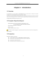
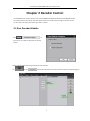
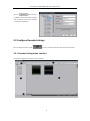
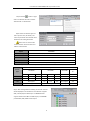
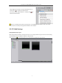
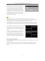
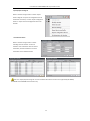
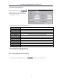
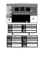
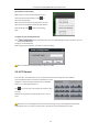
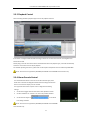
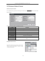
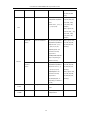
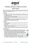
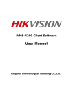
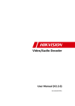
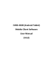
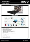
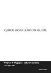
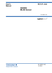
iVMS-4000 (V2.03.07) Decoder Control User Manual User Manual of iVMS-4000(V2.03.07)-Decoder Control Table of Contents Decoder Control ................................................................................................................................................. 1 User Manual....................................................................................................................................................... 1 Table of Contents ............................................................................................................................................... 1 Chapter 1 Introduction ................................................................................................................................... 2 1.1 Overview .............................................................................................................................................. 2 1.2 Computer Disposition Request ............................................................................................................. 2 1.3 Convention ........................................................................................................................................... 2 Chapter 2 Decoder Control ................................................................................................................................ 3 2.1 Run Decoder Module ........................................................................................................................... 3 2.2 Configure Decoder Settings .................................................................................................................. 4 2.2.1 Decoder Configuration Interface ............................................................................................... 4 2.2.2 Configure Decoder .................................................................................................................... 5 2.2.3 TV Wall Settings ......................................................................................................................... 7 2.2.4 Remote Decoder Configuration ............................................................................................... 10 2.3 Video Decoding Control ..................................................................................................................... 12 2.3.1 Decoding Control Interface...................................................................................................... 12 2.3.2 Video Decoding ....................................................................................................................... 14 2.3.3 Cycle Decoding ........................................................................................................................ 15 2.3.4 PTZ Control .............................................................................................................................. 16 2.3.5 Playback Control ...................................................................................................................... 17 2.3.6 Alarm Decode Control ............................................................................................................. 17 2.4 Third-party Network Camera ............................................................................................................. 18 Appendix List of Third-party Network Cameras Access .................................................................................... 19 1 User Manual of iVMS-4000(V2.03.07)-Decoder Control Chapter 1 Introduction 1.1 Overview As supplemental to the User Manual of iVMS-4000(V2.03.07), this manual aims to introduce the decoder configuration of the iVMS-4000 (V2.03.07) client application software. The decoder is used for decoding and outputting the network video signal from DVR, DVS, IP Camera and IP speed dome, and then displaying the video on TV wall. It supports multiple network transmission protocols and ensures the high stability and reliability of the system running. 1.2 Computer Disposition Request Operating System: Microsoft Windows7/Windows 2008 (32/64-bit system) Windows 2003/Windows XP/Windows 2000 (32-bit system) CPU: Intel Pentium IV 3.0 GHz or models above RAM: 1G or above Display: 1024×768 resolution or above Note: Higher hardware configuration is required for synchronous multi-camera live view or viewing video at higher resolution. 1.3 Convention Conventions as follows in this manual: The Client Software refers to the iVMS-4000 client application software. The Device refers to DVR, hybrid DVR, NVR, DVS, IP Camera and IP Dome. The Click refers to left click the mouse. The Double click refers to double left click the mouse. 2 User Manual of iVMS-4000(V2.03.07)-Decoder Control Chapter 2 Decoder Control The iVMS-4000 client software allows the access by DS-6000DI, DS-6300DI, DS-6101DI and DS-6401HDI Decoder for decoding network video signal from DVR, DVS, IP Camera and IP speed dome through the decoder module and then realize the display and switching of video on TV wall. 2.1 Run Decoder Module Click on the menu bar to enable the application of decoder module. Settings will take effect after having restarted the client software. The icon and button will be displayed on the Setup interface. Refer to the following figure: 3 User Manual of iVMS-4000(V2.03.07)-Decoder Control Click the button to enter the Modify Channel Information interface. User can edit the channel ID for switching TV wall video via keyboard. 2.2 Configure Decoder Settings Enter the Setup interface and click to run the decoder module and enter the decoder interface. 2.2.1 Decoder Configuration Interface The decoder configuration interface is shown as below: 4 User Manual of iVMS-4000(V2.03.07)-Decoder Control System Panel: Area Description Area Tab bar Description List of decode output channels Decode channel display Toolbar Configuration buttons Toolbar: 2-division display 1\4\9\16-division display Decode Output Configuration Buttons: Button Description Button Preview type Description Playback type Alarm type Decoder Layout Toolbar: Button Description Button Description Left align Right align Right align Bottom align Center vertically Center horizontally Equal horizontal Equal vertical distance distance Equal width Equal height Equal size 2.2.2 Configure Decoder If there is no decoder added in the software, the system will pop up a message box of “Add Decider Guide”. Click OK to start the guide. Step1: Follow the guide and click the “TV Wall Settings” to enter the decoder settings interface. 5 User Manual of iVMS-4000(V2.03.07)-Decoder Control Step2: Click the button or right click in the Decoder list area and select “Add decoder” to add decoder. Step3: Select the decoder type and then input the name, IP address, user name and password of the decoder. Click OK to finish the adding of decoder. Note: User can also click the “Online Decoder” button to select and add the online decoder. Option Instruction Decoder type CIF, 4CIF, 720P and 1080P are selectable Decoder name Edit the name of Decoder Decoder IP IP address of the Decoder Port Port of the Decoder Username/Password Username and password for login to the Decoder The decoding resource of DS-6000DI, DS-6300DI, DS-6101DI and DS-6401HDI is shown as below: Description Decode DS-6000DI type DS-6300DI 6001DI 6004DI 6008DI CIF 1-ch 4-ch 4CIF 1-ch 4-ch 720P Not support 1080P Not support DS-6101DI DS-6400H DI 6301DI 6304DI 6308DI 6101DI 6401HDI 8-ch 4-ch 8-ch 16-ch 4-ch 4-ch 8-ch 2-ch 4-ch 8-ch 1-ch 4-ch 1-ch 2-ch 4-ch Not support 2-ch Not support 1-ch Not support Step 4: After having added successfully, the decoder channels will be displayed in the decoder list. If the Decoder supports VGA, it will display the VGA output. The 6300DI decoder supports simultaneous BNC and VGA outputs, and 6401HDI provides BNC, VGA, HDMI and DVI output. 6 User Manual of iVMS-4000(V2.03.07)-Decoder Control Step 5: Right click a decoder and select “Modify decoder” or directly click “ ” to modify the added decoder. User can also select “Delete decoder” or directly click “ ” to delete the added decoder. Note: It is recommended to add the same decoder in one iVMS-4000 client software only so as to avoid control confusion caused by its being added in different client software. 2.2.3 TV Wall Settings Enable/Disable decode output After having added the decoder, the decode channel is not in using by default. Drag one channel to the decoding channel display area on the right to enable this output channel. User can also click “ ” on the lower right corner of the window to disable the output channel. 7 User Manual of iVMS-4000(V2.03.07)-Decoder Control Decode output settings User can double click a channel of the decoder to enter the “Decoder output settings” and configure the channel name and select video format. If the decoder provides the VGA, DVI or HDMI output, user can also select different resolution from the drop-down menu. Window division configuration By right clicking the decoder channel, user can change the window-division display mode. The section will be different depended on the device type. Different window-division display modes are selectable according to different deice type and output channel type. Refer to the following table: Decoder Type DS-6000DI Model 6001DI 6004DI 6008DI Output channel Window-division BNC output 1 1, 2, 4 1, 2, 4 1, 2, 4 1, 2, 4,9 1, 2, 4 1, 2, 4 1, 2, 4, 9, 16 1, 2, 4 1, 2, 4 1, 2, 4 DS-6100DI 6101DI BNC output VGA output BNC output VGA1 output VGA2 output BNC output VGA1 output VGA2,3,4 output BNC output DS-6401HDI 6401HDI BNC, VGA, DVI, HDMI 6301DI DS-6300DI 6304DI 6308DI 8 User Manual of iVMS-4000(V2.03.07)-Decoder Control After configuration of the window division, if it has reached the limit of decoding source, then the system will display the warning message of “Decoder channel not available!” when the user continues to enable the decode output channel. For example, in the CIF decoding type, the first two channels of 6308DI (8-channel decoding at 4CIF) have been configured with quad display, then when user tries to enable the third decoding output, the system will pop up the error message dialog box as shown in the right. Note: For DS-6300DI Series Decoder, each of the BNC output is allowed to display the decoded video from its corresponding DSP only; the first VGA output can display the decoded video from all of its DSPs, while the rest VGA output is allowed to display the decoded video from its corresponding DSP only as well. For DS-6300DI Series Decoder, only one output channel can be selected from the HDMI, DVI, BNC and VGA outputs for display each time. Please refer to the User Manual of DS-6300DI and User Manual of DS-6401HDI. After configuration of the window division, if it does not reach the limit of decoding source, when enabling decode output and exceeding decoding source, then the exceeded window will be invalid. For example, in the 4CIF decoding mode, when the first three channels of 6308DI (8-channel decoding at 4CIF) have been configured with a total of 6 windows decoding, then user is allowed to enable the fourth decoding output, however, if it is displayed in 4 windows division, then the last two decoding Decode channel position management After having enabled the decoding output and configured the display mode, user can change the size and position of the display window. Click the mouse and hold on the title below the window to change its position. By dragging a border of the decoder, user can change the size of the window. You can also use the layout toolbar to adjust the size and position. 9 User Manual of iVMS-4000(V2.03.07)-Decoder Control Decode type setting Select one sub-window and then click the top buttons to set its decode type to preview type ( ), playback type ( ) or alarm type ( ). Note: 1. Only one sub-window can be configured for alarm type. 2. Up to four sub-windows from the same decoded video output can be configured for playback type; and only 1 decoded output channel is allowable to be configured for playback type each time. Click “Save” at the top right corner to validate the new settings. Note: This function can be supported by DS-6300DI, DS-6101DI and DS-6401HDI Series Decoder only. 2.2.4 Remote Decoder Configuration Select a decoder and right click it to select “Remote Settings” to enter the decoder Remote settings interface. 10 User Manual of iVMS-4000(V2.03.07)-Decoder Control Export/Import Config File Select a decoder and right click it to select “Export device config file” to export the configuration files of the decoder to local PC, or select “Import config file to device” to import the local configuration files to the decoder. View Decoder Status Select a decoder and right click it to select “Working status of decoder” to enter its interface. User is allowed to view the stream information, decode information and show information of the selected decoder. Note: The “Export/Import Config File” and the “View Decoder Status” functions are supported by DS-6300DI, DS-6101DI and DS-6401HDI series decoder only. 11 User Manual of iVMS-4000(V2.03.07)-Decoder Control Transparent Channel Configuration Select the device and then click at the lower left corner on the “TV Wall Settings” interface to enter the “Transparent chan configure” interface. User is allowed to configure the following settings: Item Description Trans chan Select the transparent channel No. Open State Enable/disable transparent channel Local Rs Select local serial interface to RS232 or RS485 Remote Rs Select remote serial interface to RS232 or RS485 Device IP IP address of the remote device Port Port No. of the remote device User Name User name of the remote device Password Password of the remote device Duplex configure Configure the full-duplex settings 232 Duplex Select a RS-232 channel to full-duplex 485 Duplex Select a RS-485 channel to full-duplex 2.3 Video Decoding Control 2.3.1 Decoding Control Interface After adding decoder configuration, click the tag to enter decoder control interface. 12 User Manual of iVMS-4000(V2.03.07)-Decoder Control Area Instruction Area instruction Device list PTZ control panel Preset list Display of decoding channel Live view of decoded video Display of working status of selected from selected decoding channel decoding channel Add third-party network camera for the monitoring area Enter TV Wall control interface, and the decoding channel will be displayed in the area according to user-defined configuration. Click to hide the display of decoded video and status, or click to resume display. Description of the functional buttons on the interface: Button Description Button Start playing the decoded video Description Stop playing the decoded video Start cycle decoding Stop cycle decoding Preview type Playback type Start/Stop live view of locally Alarm type / Capture decoded video Record Configure the position of decode Show/hide index on the decode channel windows and select the channel window decode type 13 User Manual of iVMS-4000(V2.03.07)-Decoder Control 2.3.2 Video Decoding Select the decoding window and double click the desired channel from the device list, and then the decoder will start decoding for this channel. The real-time decoded video will be displayed on the live view panel, and the current decoding status can be viewed in the Channel list. Start/Stop decoding When the decoding is disabled, user can right click the decoding window and select “Start decoding” or click on the toolbar to start decoding. Right click the decoding channel and select “Stop decoding” or click on the toolbar to stop decoding of the current decoding window. 14 User Manual of iVMS-4000(V2.03.07)-Decoder Control Open/Close voice Right click the current decoding window and select “Open Voice” option to open voice; when the voice is turned on, right click the decoding window, and select “Close Voice” option to close voice. Decoded video control Note: Only the Audio & Video stream type can support this function. User may right click on the decoding window from VGA output to select “Full Screen” or “Original Scale” display mode. 2.3.3 Cycle Decoding Drag a device or group node to the designated decoding window, and then all channels under this device or group will be decoded in cycle. The real-time decoded video will be displayed on the live view panel, and the current decoding status will also be displayed in the Channel list. 15 User Manual of iVMS-4000(V2.03.07)-Decoder Control Pause/Resume cycle decoding Right click the current cycle decoding window, and select the “Pause cycle decoding” or click to pause the cycle decoding. When the cycle decoding is in paused status, user may right click on the decoding window and select Resume cycle decoding or click to start cycle decoding again. Configure the cycle decoding dwell time Click button at the lower left corner of TV Wall Settings interface to enter the menu for setting the TV wall dwell time. After configuring the dwell time, click “Save” to save the settings. Note: The dwell time of cycle decoding can be set to 5~300s. 2.3.4 PTZ Control If the decoder is connected with PTZ, user can operate the PTZ control through the client software. There are 8 directional keys to control PTZ movement, and the sliding bar is used to change PTZ speed, which is adjustable from 1 to 7, and the default speed is 4. Click key to start auto scanning and click it again to stop scanning. Click the function keys on the right to adjust focus, iris and zoom. Note: If the current decoding window is under cycle decoding, the cycle decoding will be paused while operating PTZ control; and when the PTZ control is finished, the cycle decoding will be resumed. 16 User Manual of iVMS-4000(V2.03.07)-Decoder Control 2.3.5 Playback Control Click a decoding window of playback type to enter the playback interface. If the device is configured with the NVR recording, it allows user to select the search of recording files from Device Disk or NVR. Directly drag a channel of the device to the decode window division of playback type, and it will automatically search the record of the current day for playback. For detailed operating instructions, please refer to the Chapter of Playback in the User Manual of iVMS-4000. Note: This function is supported by DS-6300DI, DS-6101DI and DS-6401HDI series decoder only. 2.3.6 Alarm Decode Control The decode window division can be set to the alarm decode type, which allows user to decode the designated alarm linked recording channel when alarm occurs and then display it on the TV Wall. The support of this function requires user to configure the following settings: 1. Set the alarm trigger method of the device with “Upload to center”. 2. Set “Arm software” for a device or an area in the preview interface. 3. Set the alarm link type to in the Alarm Link settings interface. Note: This function is supported by DS-6300DI, DS-6101DI and DS-6401HDI series decoder only. 17 User Manual of iVMS-4000(V2.03.07)-Decoder Control 2.4 Third-party Network Camera Add Third-party Network Camera In the TV Wall interface, right click the monitoring site and then click the button to enter the Add Device dialog box. Configure the following settings in the Add Device interface: Item Description Device Name Edit the device name Register Mode Select the register mode to Normal IP or Normal Domain Device IP IP address of the added device Port Port No. of the added device Username User name for login to the device Password Password for login to the device Channel No. Channel No. of the added device Belong to area Monitor area to which the device belongs Manu Type Third-party network camera manufacturer, e.g., PANASONIC, SONY, AXIS, etc. Modify/Delete Network Camera Right click the added third-party network camera from the device list, and then select “Modify” or “Delete” to modify or delete the added device. 18 User Manual of iVMS-4000(V2.03.07)-Decoder Control Appendix List of Third-party Network Cameras Access IPC Model Firmware Version Supported Resolution Supported BitRate WV- 1.00Ex(x stands for 640×480/320×240 CBR: (support: 64, NP240 numeric) (not support frame rate 128, 256, 512, 1024, settings) 1536, 2048, 3072, Manufacturer Panasonic Series 4096kbps) SNC-DF40/DF 1.03 70 Sony 640×480/480×360/384 VBR: (support: 2048, ×288/320×240/256×19 1536, 1024, 768, 2/160×120(frame rate: 512, 384, 256, 128, 25, 20, 15, 10, 8, 6, 5, 4, 64 kbps) 3, 2, 1) CBR: (support: 2048, 1536, 1024, 768, 512, 384, 256, 128, 64 kbps) 207W/20 4.4 7MW 640×480/1280×1024/1 VBR: (support: 64, 280×720/1280×960/12 128, 256, 512, 1024, 80×480/480×360/480× 1536, 2048, 3072, or 270/352×288/320×240/ self-defined 32-8192 320×180/240×180/240 kbps) ×135/176×144/160×12 CBR: (support: 64, 0/160×90 128, 256, 512, 1024, (frame rate: 25, 20, 15, 1536, 2048, 3072, or 10, 8, 6, 5, 4, 3, 2, 1) self-defined 32-8192 kbps) Axis Q1755 5.02 1920×1080/1280×720/ VBR: (support: 64, 800×450/480×270/320 128, 256, 512, 1024, ×180 1536, 2048, 3072, or (frame rate: 25, 20, 15, self-defined 32-8192 10, 8, 6, 5, 4, 3, 2, 1) kbps) CBR: (support: 64, 128, 256, 512, 1024, 1536, 2048, 3072, or self-defined 32-8192 kbps) 19 User Manual of iVMS-4000(V2.03.07)-Decoder Control VCC-HD4 MAIN Ver: 1.04-90 1280×720/960×540/64 000 SUB Ver: 1.00-03 0×360/320×180 Not support (not support frame rate settings) VCC-H500 Sanyo CAM MAIN Ver 1280×720/640×360/32 1.00-08; 0×180 CAM SUB Ver (not support frame rate 1.00-00; settings) Not support NET MAIN ver 1.00-04; NET SUB Ver 1.00-01 VCC-HD2 MAIN Ver: 1920×1080/1280×720/ 300 1.01-01(100312-03); 640×360/320×180 SUB Ver: (not support frame 1.00-02(100224-00) rate settings) 18500400 640×480/320×240/704 VBR: (not support) ×576/704×288/352×28 CBR: (support: 2048, 8/176×144 1536, 1024, 512, (not support frame 384, 256, 128, 64, or rate settings) self-defined 32-8192 (Note: the resolution kbps) NBC255P Not support actually supported is 640×480/320×240, or depending on different model) Bosch NWC0495 18500400 640×480/320×240/704 VBR: (not support) ×576/704×288/352×28 CBR: (support: 2048, 8/176×144 1536, 1024, 512, (not support frame 384, 256, 128, 64, rate settings) self-defined 32-8192 (Note: the resolution kbps) actually supported is 704×576/704×288/35 2×288/176×144, or depending on different model) f3105 MG.0.5.1.01 Zavio 320×240/640×480/128 VBR: (support: 64, 0×720/1280×1024 128, 256, 384, 512, (frame rate: 1, 2, 3, 4, 5, 768, 1M, 1.5M, 2M, 7, 10, 15, 20, 30) 3M, 4M, 5M, 6M kbps CBR: (support: 64, 128, 256, 384, 512, 20 User Manual of iVMS-4000(V2.03.07)-Decoder Control 768, 1M, 1.5M, 2M, 3M, 4M, 5M, 6M kbps) acm7411 V3.11.13 ACTi 160×112/320×240/640 VBR: (support: 56, ×480/1280×720/1280× 128, 256, 384, 512, 1024 750, 1024, 1.2M, (frame rate: 1, 2, 3, 4, 5, 1.5M, 2M, 2.5M, 6, 7, 10, 15, 30) 3Mkbps) CBR: (support: 56, 128, 256, 384, 512, 750, 1024, 1.2M, 1.5M, 2M, 2.5M, 3Mkbps) V6201-M 1.02.110.20090903 Series D1/2CIF/CIF/QCIF/640× CBR: (support: 256, 480/1280×720/1280×9 512, 1M, 2M, 3M, 60(frame rate: 1, 2, 4, 4M, 5M, 6M, 7M, 6, 8,10, 12, 15, 20, 8M kbps) 30N/25P) (Note: the resolution actually supported is 640480/1280720/1280 960, or depending on Infinova different model) SD Network 1.03.71.20091229 D1/2CIF/CIF/QCIF/640× VBR: (support: 256, Camera 480/1280×720/1280×9 512, 1M, 2M, 3M, Series 60 (frame rate: 1, 2, 4, 4M, 5M, 6M, 7M, 6, 8, 10, 12, 15, 20, 8M kbps) 30N/25P)(Note: the CBR: (support: 256, resolution actually 512, 1M, 2M, 3M, supported is 4M, 5M, 6M, 7M, D1/2CIF/CIF/QCIF, or 8M kbps) depending on different model) SNIPV54/00 V1.5_build042015 704×576/352×288/176 Sunell VBR/CBR ×144 VSIP4 VSS-441 V1.2.3.1 704×576/704×288/352 ATEME ×288/176×144 21 VBR/CBR/CVQ