1
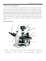
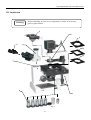
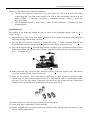
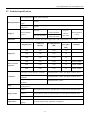
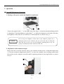
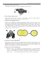
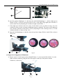
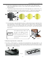
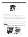
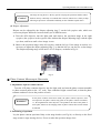
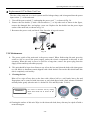
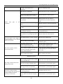
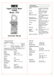
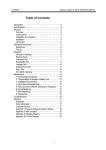
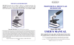
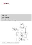
Inverted Microscope
Model
82026-630
Operating Manual
Operating Manual of Inverted Microscope
Congratulations !
Thank You for your purchase of a VWR VistaVision Microscope
This unit is a precision optical instrument. Our product has been design to provide the highest level of
safety. However, improper operation or negligence in following the instructions in this manual may
cause personal injuries and property losses. In order to ensure your safety, to maximize the life of this
unit and to maintain it properly, please read through this manual carefully before operating this unit.
-1-
Operating Manual of Inverted Microscope
Safety Precautions & Reminder
!
Warning!
1. Be sure to turn off the power switch and remove the power cord plug before
installing this unit, replacing the bulb / fuse or plugging and unplugging the
power supply unit. This is to prevent electric shock or getting fingers burnt.
!
Warning!
2.Check unit voltage is in compliance with your local power supply voltage,
otherwise contact your supplier. Improper input voltage may render unit not
workable or a short circuit and damage the unit.
!
Warning!
3.Use specified bulb, fuse and power cord which otherwise may damage the unit.
Any extended power cord if used, must be grounded (PE).
!
Warning!
4. Do not expose unit to high temperatures and dampness. Suitable operating
environment is between 5°C to 35°C, and relative humidity of 20%-80% (at
25°C). Do not subject unit to direct sunlight.
!
Warning!
5. Do not touch the halogen lamp box when using the unit as bulbs inside
generate excess heat which can burn your hand. Do not handle bulb with bare
minutes
after
switching
off
power
hand
within
10
supply as bulb is still hot, especially when changing a defective bulb.
!
Warning!
!
Warning!
6. To prevent fire, do not place any fibrous product, paper, flammable or
explosive material (e.g., gasoline, petroleum ether, alcohol) near the halogen
lamp box .
7.When using coarse / fine focus knobs or height adjustment knob, do not
continue to turn them beyond the limits or the internal mechanism can be
damaged..
-2-
Operating Manual of Inverted Microscope
Table of Contents
I. Characteristics and applications .................................................................................................. - 1 II. Structural features ............................................................................................................................. - 1 III. Installation of this unit ..................................................................................................................... - 2 IV. Technical specifications .................................................................................................................... - 4 V . Operation............................................................................................................................................... - 5 VI. Replacement of bulb and fuse ...................................................................................................... - 13 VII. Maintenance ..................................................................................................................................... - 14 VIII. Troubleshooting ............................................................................................................................. - 15 -
-3-
Operating Manual of Inverted Microscope
I. Characteristics and applications
The inverted microscope adopts an inverted structure that focuses by lifting or lowering the
objectives, and is provided with long working distance plan objectives and Wide-field plan eyepieces.
The long working distance condenser system can be placed into or out of the light path, and is suitable
for tissue observation in a high culture dish. The phase contrast device can be attached to the light path
to perform transmitted phase contrast microscopic observation. This unit is suitable for the microscopic
observation of cells, tissues and clear liquid tissues, and the dynamic microscopic observation of tissues
cultured in a culture dish, and is applicable to scientific research institutions, colleges and universities,
medical and health, inspection and quarantine agencies, agricultural, animal husbandry and dairy
industries.
II. Structural features
1
2
3
4
5
6
7
8
10
9
Fig.1
1. Eyepiece 2. Trinocular head 3. Phase contrast condenser
6. Mechanical stage 7. Objective 8. Nosepiece
-1-
4. Halogen lamp box 5. Body frame
9. Coarse/fine focusing knob 10. Eyepiece tube
Operating Manual of Inverted Microscope
III. Installation
Caution!
Before installing, be sure every components is clean, no score any
parts or glass surface.
4
3
2
5
6
(2)
(2)
7
8
1
Fig. 2
-2-
Operating Manual of Inverted Microscope
There are 2 styrofoam boxes within the carton box.
a) The first box contains 6 objectives (3 pcs plan objectives 10X, 25X & 40X with single
colored ring and 3 pcs plan phase contrast 10X, 25X & 40X with double colored rings and
marked “PHP2”), 1 trinocular, 2 eyepieces, 1 centering telescope, 3 filters , 1 spare fuse
and1 spare lamp.
b) The Second box contains 1 body frame, 1 phase contrast condenser, 3 different size stage
brackets holders.
Installation steps
The number in the following installation steps is shown in the installing diagram, such as “1” is
“Body” in Fig.2
(1) Unpack this unit, take out the body frame 1 and place it on a stable work bench, and remove the
supporting package and the dust cap (bag).
(2) Take out the phase contrast condenser 4. Loosen the screw ① on the condenser holder 3 and
then install the condenser into the holder, tighten the screw again. As shown in Fig. 3.
(3) Take out the stage bracket 2 (when the stage bracket is used to carry a specimen or observe tissue
in the culture dish), put the desired specification stage bracket flatly in the stage moving device
rack ②. As shown in Fig. 3.
②
Fig.3
①
(4) Remove the dust cap of eyepiece tube, insert the eyepiece 5 into the eyepiece tube, and turn the
eyepieces so that it fits the eyepiece tube well.
(5) There are 6 objectives. Those with single colored ring are plan objectives and with double
colored rings are phase contrast objectives which are also marked “PHP2”. Install them onto the
nose piece. User can only mount 5 objectives onto the nose piece at any one time. Install them
clockwise in the ascending order of magnification As shown in Fig.4.
Fig.4
(6) Connect the power cord to the power supply socket of the body.
(7) Check if the above installation is secure and safe.
(8) Inspect and gather the accessories and tools enclosed in the package and keep them in a safe
place to avoid misplacement.
-3-
Operating Manual of Inverted Microscope
IV. Technical specifications
Total magnification 100X-400X (standard)
Main parameters
Mechanical tube
length
160mm
Conjugate distance
195mm
of objective
Eyepiece
Trinocular
Objectives
Phase-contrast
objective
Condenser
Stage
Stage bracket
Light source
Wide-field plan
eyepiece
WF 10X
field of view
number Ф20mm
WF 16X (optional)
field of view
number Ф11mm
Eyepiece
interface
Ф23.2mm
Parfocal distance
10mm
Hinged binocular tube, with an observation angle of 30°, and a pupil distance of 53-75mm
Magnification
Numerical
aperture
Working distance
(mm)
Thickness of
cover glass
(mm)
10X
0.25
8.80
1.2
25X
0.40
4.78
1.2
40X
0.60
3.32
1.2
10X
0.25
8.80
1.2
Remark “PHP2”
25X
0.40
4.78
1.2
Remark “PHP2”
40X
0.60
3.32
1.2
Remark “PHP2”
Remarks
Ultra-long working distance condenser
Working distance 55mm, with phase-contrast device
long working distance condenser
(optional)
Working distance 35mm, with phase-contrast device
Long working distance condenser
(optional)
Working distance 70mm
Mechanical Stage, moving range 79mm (longitudinal)X130mm (transverse), detachable stage
moving device
Holder 1
86mm (W)X129.5mm (L), optional with a circular culture dish Ф87.5mm
Holder 2
34mm (W)X77.5mm (L), optional with a circular culture dish Ф68.5mm
Holder 3
57mm (W)X82mm (L)
Transmitted
lighting
6V/30W halogen lamp, adjustable in brightness
-4-
Operating Manual of Inverted Microscope
V. Operation
● Inverted Microscope Operation.
1. Turning on the power switch and brightness adjustment
②
Fig. 5
①
Turn on the toggle switch ① on the right of the body frame , so that the transmitted halogen bulb
is illuminated. Turn the brightness control knob ② to adjust the brightness of the bulb, and make
the brightness of the field of view suitable for visual inspection. As shown in Fig. 5.
Caution!
Do not keep the brightness control knob at the brightest position for a
prolonged period of time, otherwise the life of the bulb may be shortened!
When this unit is not in use, turn the brightness adjusting knob to the low
position to maintain the electric functions of this unit.
2. Adjustment of the condenser height
Before this unit is released from the factory, the condenser already bears a calibrated height mark
①, Turn the condenser height control knob ②, to move the condenser into working position until
the two lines on the condenser coincide which is optimum position for most applications. as shown
in Fig. 6.
①
②
Fig. 6
-5-
Operating Manual of Inverted Microscope
3. Adjustment of phase-contrast device
Set the phase contrast puller ① to the central light hole, as shown in Fig.7.
①
Fig. 7
4. Reset of diopter adjustment ring
Turn the diopter adjustment ring ① on the left eyepiece tube, so that the “0” diopter position is
aligned with the side scale (remark white line), as shown in Fig.8.
5. Adjustment of interpupillary distance
Parallax can be eliminated by adjusting the interpupillary distance so that the distance of the
eyepiece tube is identical with your interpupillary distance and enable you to observe more
comfortably and clearly. When you observe through two eyepieces, if the field of view consists of
two overlapping circles, as shown Fig.8-a, you can alter the exit pupil center distance of the
eyepiece tubes by turning the left or right frame body ② until the field of view becomes a fully
overlapped circle, as shown in Fig. 8-b.
①
②
a
b
Fig. 8
6. Inspection of transmitted lighting path
The optical system of this unit has been calibrated before factory release. But the center of the
lighting bulb or condenser system may deviate from the center of the optical system due to any
possible violent vibration or inclination during transport. After the above installation and
adjustment, the light path of the optical system should be checked.
(1) Inspection of center of field diaphragm
A. Put the test slide ①.as an example in the selected Stage bracket ②. Turn the 10X plan
objective ③ into the light path. Turn the stage moving device control knob and ④ and ⑤
to move the slide right above the 10X objective. Adjust the focus by the coarse and fine focus
knobs ⑥ and ⑦ to make the image of slide in the field of view clear. As shown Fig.9.
-6-
Operating Manual of Inverted Microscope
③
②
④
⑦
⑤
①
⑥
Fig.9
B. open the aperture diaphragm ④, and close the small field diaphragm ①, when a light spot as
shown in Fig.11-a can be seen in the field of view. If the edge of the light spot is unclear, it
can be made clear by adjusting the condenser height control knob ②.
C. If the light spot deviates from the center of the field of view, as shown in Fig. 10-a, the
condenser center (center of aperture diaphragm) must be adjusted. The center of the light spot
can coincide with that of the field of view by adjusting two the centering screws ③ of the
condenser holder, as shown in Fig. 10-b.
D. Open the field diaphragm, so that the observed specimen image fills the visual field, as shown
in Fig.10-c.
①
a
②
b
c
④
③
Fig.10
(2) Inspection of alignment of illuminator
A. Prepare a piece of white paper (about 40mmX50mm) ③, unscrew the filter holder ② on the
phase contrast condenser, and place the white paper on the top of the phase contrast
condenser, as shown in Fig. 11.
①
②
Fig.11
-7-
③
Operating Manual of Inverted Microscope
B. At this point, a bright light spot will be shown on the white paper, with a filament image
inside. If the filament image is unclear, it can be made clear by adjusting the collector lens
adjusting handle ④.
C.
If the filament image deviates from the center of the bright light spot, as shown in Fig. 12-a,
the bulb must be centered. To do this, loosen the screws ⑦, and move the lamp holder ⑥
gently adjust the left-right centering of the bulb, as indicated by the arrow in the figure.
⑤
④
⑥
⑦
a
b
c
Fig.12
D. If it is necessary to center the bulb front and rear as indicated by the arrow in the Fig.12, the
whole lamp holder ⑩ and the bulb ⑨, must be removed as shown in Fig.13. This cannot be
done until the bulb is cool. Wrap the bulb with a cotton fabric ⑧, and adjust the bulb
vertically gently (in the direction indicated by the arrow in Fig.13). This can center the bulb
front and rear.
Do not adjust the bulb too hard, as this
will add to the difficulty of precise
adjustment. The bulb should not be
Caution!
removed for adjustment until it is cool. Do
not pull the bulb too hard, otherwise the
feet may burst.
⑧
⑨
⑩
Fig. 13
7. Placement of specimen slice or culture dish
(1) To observe a slide specimen ①, the slide can be placed directly on the stage bracket ②. To
observe tissues in a culture dish, determine the stage bracket to be used based on the external
dimensions of the culture dish (refer to the technical specification table for the allowable culture
dish dimensions), as shown in Fig.14.
①
②
Fig. 14
-8-
Operating Manual of Inverted Microscope
(2) Adjust the stage moving device control knob ① and ② so that the observed area is right above
the objective for easy observation and adjustment, as shown in Fig. 15.
①
②
Fig.15
8. Coarse and fine focusing control knob operation
(1) Focus with the 10X objective
Turn the nosepiece ① to move the 10X objective into the light path (when it turns in place, the
objective will snap automatically), as shown in Fig. 16.
(2) Turn the coarse focusing control knob ③ to lift the objective to the highest point. Then observe
through the eyepiece. Turn the coarse focusing control knob slowly to lower the objective. When
a specimen image appears in the field of view, stop turning the coarse focusing control knob, as
shown in Fig. 16.
(3) Turn the fine focusing control knob ② for fine focusing to make the specimen image clear, as
shown in Fig.16.
(4) Lock the objective lifting limit hand wheel ④ as indicated by the arrow in the figure, as shown in
Fig. 16.
Reminder!
When you’re going to use a high-power objective, first use the 10X objective
to focus and set the limit hand wheel. When mounting a high-power
objective, raise the objective to the limit height with a coarse focusing control
knob directly, and then focus finely with the fine focusing control knob.
①
Fig.16
②
-9-
③
④
Operating Manual of Inverted Microscope
9. Adjustment, assembly and removal of stage moving device
(1) The longitudinal (Y) and transverse (X) movement of the stage moving device ① is realized by
the longitudinal adjusting knob ② and the transverse adjusting knob ③ that are coaxial, as
shown in Fig. 17.
Caution!
The stage moving device is driven by gear and rack. In case of longitudinal or
transverse movement to the fixed position (maximum), do not continue to turn
the adjusting knob as this is likely to damage the movement adjusting
mechanism. When the stage moving device protrudes from the fixed stage, the
rack will extend outward. Be careful not to let the rack hit your hand or any
other part of your body.
①
Y
X
②
③
Fig. 17
(2) If observing tissues in a big culture dish, the stage moving scale ① on the fixed stage must be
removed. During removal, keep the condenser system ④ out of the light path, remove the stage
bracket, and lower the objective (turn the coarse focusing control knob so that the objective
lifting mechanism is lowered). Use a screwdriver to loosen the 3 mounting screws ⑤ at the
bottom of the stage moving device, remove the stage moving device ⑥, and lay it flatly on the
worktable upside down. Do not lay it laterally or overhead, otherwise it may drop or be deformed,
affecting the precision of this device. See Fig. 18 for the operating process.
④
⑥
⑤
Fig.18
- 10 -
Operating Manual of Inverted Microscope
Caution!
The stage moving device is the key part for carrying the specimen and the culture
dish. Do not lay it laterally or overhead after removal, otherwise it is likely to drop,
affecting its precision. It should be laid flatly on the worktable upside down.
(3) Diopter adjustment
Diopter can be adjusted by the diopter adjusting ring ① on the left eyepiece tube, which can
correct any diopter difference between both eyes of different users.
A. Turn the 40X objective into the light path, and observe the specimen image in the right
eyepiece (the eyepiece in the eyepiece tube without the diopter adjusting ring) with the right
eye alone, and focus until a clear image is seen.
B. Observe the specimen image in the left eyepiece with the left eye. If the image is unclear, it is
necessary to adjust the diopter adjusting ring ① so that the left eye can also see a clear image.
The diopter adjusting range of this unit is N=±5 diopters, as shown in Fig.19.
①
Fig. 19
● Phase Contrast Microscopic Observation
1. Adjustment of phase contrast device
Turn the 10X phase contrast objective into the light path, and turn the phase contrast turntable
or phase contrast puller to the “10” scale. Turn condenser height control knob, so that the phase
contrast condenser rises to the position of scale.
Reminder!
In the phase contrast observation mode, the phase contrast objective must
correspond to the phase contrast ring plate in the phase contrast condenser,
i.e., the magnification of the objective corresponds to the scale of the puller or
insert plate, otherwise the imaging effect of phase contrast observation would
be affected.
2. Positioning of specimen
Lay the phase contrast specimen flatly on the stage bracket (see Fig.14) or directly on the fixed
stage (remove stage moving device). Focus to make the specimen image clear.
- 11 -
Operating Manual of Inverted Microscope
3. Centering of phase contrast device
(1) Remove one eyepiece from the eyepiece tube, and insert the centering eyepiece ②
eyepiece tube, as shown in Fig. 20-a.
into the
(2) A dark ring ④ and a bright ring ⑤ can be observed in the field of view of the centering
eyepiece, as shown in Fig. 20-c.
(3) If the edge of the dark rings and bright rings is unclear in the field of view, the adjusting ring ①
of the centering eyepiece can be adjusted to make the edge clear.
(4) In the phase contrast observation mode, the center of the dark ring should coincide with that of
the bright ring. If their centers do not coincide, as shown in Fig. 20-c, it is necessary to center the
phase contrast. This can be done by adjusting the centering screws ③ of the puller phase contrast.
The adjusted the field of view is as shown in Fig. 20-d.
(5) After the phase contrast device is centered, the centering eyepiece can be removed, and the
working eyepiece inserted again.
Caution!
In case of changeover to a phase-contrast objective of a different magnification, the
phase-contrast device must be centered again, otherwise the effect of observation
phase-contrast would be affected.
④
⑤
①
②
c
a
③
d
b
Fig.20
- 12 -
Operating Manual of Inverted Microscope
● Operation of Trinocular Device
This unit performs visual inspection and photographic observation through push-pull changeover.
1 Loosen the fastening screws ② of the photographic output tube, and remove the dust cap ① of
the photographic output tube as shown on Fig 21
2
Mount the photographic device on the output tube, and then tighten the fastening screws.
3
Pull out the photographic/visual changeover pusher ③ , the image will show in the monitor or
display screen
①
②
③
Fig.21
VI. Replacement of bulb and fuse
!
Warning!
To replace the bulb and the fuse, turn off the power switch and unplug the
power cord, otherwise fire, personal injury or damage to this unit may
occur due to electric short circuit.
● Halogen Lamp Replacement
1. Turn off the power switch ①, and unplug the power cord ②, as shown in Fig. 23-a, 23- b.
2. Wait at least 10 minutes until the bulb and its surroundings have cool down. This is to prevent
hand getting burnt by heat.
3. Unscrew the screw ⑤, loosen the screw ④, and pull out the lamp holder from the halogen lamp
housing. Use a cloth to remove the defective bulb as it may still be very hot after use. Replace
the halogen bulb and place back the lamp holder into position. The bulb feet should be inserted
as deeply as possible, otherwise the life of the bulb may be shortened due to bad contact or the
bulb may not be illuminated. As shown in Fig. 23-d.
4. Check and adjust the center of the bulb according to the above-mentioned centering method for
the alignment of illuminator in the inverted microscope operation.
④
⑤
③
a
①
b
②
c
Fig. 23
- 13 -
d
Operating Manual of Inverted Microscope
● Replacement Of The Main Unit Fuse
The fuse of the main unit is a circuit system used for halogen lamp, and is integrated into the power
input socket ③ of the main unit.
1.
Turn off the power switch ①, and unplug the power cord ②, as shown in Fig. 24.
2.
Remove the fuse holder ② with a flat screwdriver ① or any other tool as shown in the figure,
remove the damaged fuse, and replace a new one. Replace the fuse holder into the power input
socket of the main unit, as shown in Fig. 24.
3. Reconnect the power cord, and check if the fuse tube is in good contact.
③
①
②
Fig. 24
VII. Maintenance
1.
The power switch of the main unit is the power control. When finish using this unit, press the
switch to “O” to cut off the power supply, unless the electric components in this unit is still
operating. When this unit is not to be used for a long time, remove the power plug from the
supply socket and keep all cables properly.
2.
This unit should be kept clean. Remove any oil on the lens and clean the body with clean gauze
(or silk fabric or absorbent cotton) dipped with a little alcohol. Put on the dust shield until this
unit is completely cool and dry.
3.
Cleaning the lens
Blow off or wipe off any dust on the lens with a blower ball or a soft brush; heavy dirt and
fingerprints can be removed with lens tissue or soft cloth dipped with a little mixture of alcohol
and ethyl ether gently (the mix ratio is: alcohol 20-30% and ethyl ether 70-80%).
Reminder!
It is easier to clean the lens by wiping
them from inside out as shown in the
figure.
Wrong
Right
4. Cleaning the surface of this unit: Wipe it with clean soft cloth; heavy dirt may be wiped off with a
neutral detergent.
- 14 -
Operating Manual of Inverted Microscope
5. Keeping: When this unit is not to be used for a long time, turn off the power supply of this unit,
allow the bulb to cool down sufficiently, put on the dust shield, store this unit at a dry, ventilated
and clean place free from any acid, alkali or steam, otherwise mold may develop on the lens.
6. Periodic inspection: This unit should be inspected and maintained periodically to maintain its
performance.
Caution!
Do not wipe this unit with any organic solvent (e.g., alcohol, ethyl ether or its
dilute solution), otherwise the surface paint of this unit may come off. It is
suggested that a layer of non-corrosive lubricant is applied on the moving
parts of this unit before the dust shield is put on, and place the eyepiece and
the objectives in a container with desiccant.
VIII. Troubleshooting
Fault
Cause
Solution
Electric system
No light shown in the field of
view using halogen lamp
The power switch is not turned on.
Turn on the power switch.
The halogen lamp is damaged.
Replace the halogen lamp.
The fuse is damaged.
Replace the fuse.
The connector of the electric chassis is
Check and have a professional repair it.
in bad contact.
The halogen lamp mounted is
nonconforming.
Use a conforming halogen lamp.
Optical system and imaging
There is a black shadow on the
edge of the field of view or
unevenly illuminated, making it
impossible to observe the whole
field of view.
The nosepiece has not been turned to
the fixed position.
Turn the nosepiece to the fixed position.
The filament image deviates from the
center of the collector.
Reposition the lighting bulb.
There is dirt or oil on the surface of the
Wipe the lens surface or replace the lens.
objective, eyepiece or condenser
The field of view diaphragm is not
open completely. .
Oil or dust is found in the field of There is oil or dust on the eyepiece
view.
lens.
- 15 -
Open the field of view diaphragm.
Wipe the eyepiece.
Operating Manual of Inverted Microscope
There is oil or any foreign object on
the edge of the field of view
diaphragm.
Wipe the diaphragm edge.
The objective is damaged.
Repair the objective (by a professional).
There is oil or dust on the surface of
the lens of the objective or eyepiece.
Wipe the objective or the eyepiece.
Adjust the aperture of the aperture
The aperture of the aperture diaphragm diaphragm based on the objective
is too small.
magnification (or numerical aperture)
used.
Offset focal
resolution
plan
or
low
The objective deviates from the light
path.
Turn the nosepiece to the fixed position.
The specimen cover glass is too thick
or thin.
Load a cover glass as necessary for the
objective.
The upper and lower sides of the
specimen are inverted.
Place the upper and lower sides of the
specimen positively.
The oil has not bee wiped off timely
and remains for a prolonged period of
time.
Wipe the front lens of the objective.
The focal plane of the image is The lighting bulb is seriously inclined.
inclined (brighter on one side and
darker on the other)
The specimen is not laid flatly.
The effect of phase-contrast
observation is bad.
Reposition the lighting bulb.
Lay the specimen flatly on the object stage
and hold it stably.
The phase-contrast objective does not
match the ring plate of the
phase-contrast condenser lens.
The center of the ring plate of the
phase contrast condenser lens deviates
from that of the phase plate of the
phase contrast objective.
Align the phase-contrast objective with
the mark on the turntable of the
phase-contrast condenser lens.
The specimen used is not suitable for
phase-contrast observation.
Replace it with one suitable for
phase-contrast observation.
Center the phase-contrast condenser lens,
so that the ring plate coincides with the
phase plate.
Mechanical system
The image cannot remain clear
during observation.
The focusing mechanism flows (slides
down) automatically.
Adjust the coarse adjusting hand wheel.
The fine focusing mechanism fails
Check and have a professional repair it.
The stage loosens or is inclined.
Check and have a professional repair it.
The lock screws loosen, making
When the condenser lifting
positioning difficult.
device swings in or out, the fixed
The locking mechanism is seriously
position cannot be located
worn, and has insufficient clamping
precisely or is insecure.
force.
- 16 -
Recalibrate the lock screws.
Check and have a professional repair it.