1
UM1846
User manual
STM32F3 series safety manual
Introduction
This document describes how to use the STM32F3 series microcontrollers in the context of
a safety-related system, specifying the user's responsibilities for installation and operation in
order to reach the targeted safety integrity level. This manual applies to the STM32F3 series
microcontrollers and STM32-SafeSIL part number.
If the STM32F3 series microcontrollers are used in adherence to this manual, the system
designer can avoid going into the details of the functional safety design and validation to
give an estimation about the impact to the overall safety function.
This manual is written in compliance with IEC 61508. It also indicates how to use the
STM32F3 series microcontrollers in the context of other functional safety standards such as
safety machine directives ISO 13849. This manual and FMEDA data were developed in
cooperation with the safety expertise company Yogitech using their faultRobust
Methodology (fRMethodology).
The safety analysis summarized in this manual takes into account the variation in terms of
memory size, internal peripheral number and presence and package between the different
part numbers of the ARM® Cortex®-M4 based STM32F3 series microcontrollers.
This manual has to be read along with the technical documentation on related part numbers
(such as Reference Manuals and Datasheets) available on www.st.com.
January 2015
DocID027264 Rev 2
1/92
www.st.com
1
Contents
UM1846
Contents
1
2
3
About this document . . . . . . . . . . . . . . . . . . . . . . . . . . . . . . . . . . . . . . . . 7
1.1
Purpose and scope . . . . . . . . . . . . . . . . . . . . . . . . . . . . . . . . . . . . . . . . . . 7
1.2
Terms and abbreviations . . . . . . . . . . . . . . . . . . . . . . . . . . . . . . . . . . . . . . 7
1.3
Reference normative . . . . . . . . . . . . . . . . . . . . . . . . . . . . . . . . . . . . . . . . . 8
STM32F3 series microcontrollers development process . . . . . . . . . . 10
2.1
STMicroelectronics standard development process . . . . . . . . . . . . . . . . . 10
2.2
Yogitech fRMethodology process . . . . . . . . . . . . . . . . . . . . . . . . . . . . . . . 12
Reference safety architecture . . . . . . . . . . . . . . . . . . . . . . . . . . . . . . . . 13
3.1
Introduction . . . . . . . . . . . . . . . . . . . . . . . . . . . . . . . . . . . . . . . . . . . . . . . . 13
3.2
Compliant item . . . . . . . . . . . . . . . . . . . . . . . . . . . . . . . . . . . . . . . . . . . . . 13
3.3
3.2.1
Definition of the compliant item . . . . . . . . . . . . . . . . . . . . . . . . . . . . . . . 13
3.2.2
Safety functions performed by the compliant item . . . . . . . . . . . . . . . . . 14
Assumed requirements . . . . . . . . . . . . . . . . . . . . . . . . . . . . . . . . . . . . . . . 15
3.3.1
2/92
Assumed safety requirements . . . . . . . . . . . . . . . . . . . . . . . . . . . . . . . . 15
3.4
Electrical specifications and environment limits . . . . . . . . . . . . . . . . . . . . 16
3.5
Systematic safety integrity . . . . . . . . . . . . . . . . . . . . . . . . . . . . . . . . . . . . 17
3.6
Description of hardware and software diagnostics . . . . . . . . . . . . . . . . . . 17
3.6.1
Cortex®-M4 CPU . . . . . . . . . . . . . . . . . . . . . . . . . . . . . . . . . . . . . . . . . . 17
3.6.2
System FLASH memory . . . . . . . . . . . . . . . . . . . . . . . . . . . . . . . . . . . . 20
3.6.3
System SRAM memory . . . . . . . . . . . . . . . . . . . . . . . . . . . . . . . . . . . . . 21
3.6.4
System bus interconnect . . . . . . . . . . . . . . . . . . . . . . . . . . . . . . . . . . . . 22
3.6.5
Flexible Static Memory Controller (FSMC) . . . . . . . . . . . . . . . . . . . . . . 22
3.6.6
NVIC and EXTI controller . . . . . . . . . . . . . . . . . . . . . . . . . . . . . . . . . . . 23
3.6.7
DMA . . . . . . . . . . . . . . . . . . . . . . . . . . . . . . . . . . . . . . . . . . . . . . . . . . . . 24
3.6.8
CAN1/2 . . . . . . . . . . . . . . . . . . . . . . . . . . . . . . . . . . . . . . . . . . . . . . . . . 24
3.6.9
HDMI CEC module . . . . . . . . . . . . . . . . . . . . . . . . . . . . . . . . . . . . . . . . 25
3.6.10
USART 1/2/3/4/5 . . . . . . . . . . . . . . . . . . . . . . . . . . . . . . . . . . . . . . . . . . 26
3.6.11
I2C 1/2/3 . . . . . . . . . . . . . . . . . . . . . . . . . . . . . . . . . . . . . . . . . . . . . . . . 27
3.6.12
SPI 1/2/3 . . . . . . . . . . . . . . . . . . . . . . . . . . . . . . . . . . . . . . . . . . . . . . . . 28
3.6.13
USB - 2.0 Universal Serial Bus interface HS/FS modules . . . . . . . . . . . 29
3.6.14
Touch Sensing Controller (TSC) . . . . . . . . . . . . . . . . . . . . . . . . . . . . . . 29
DocID027264 Rev 2
UM1846
Contents
3.7
4
Analog to Digital Converters (ADC) . . . . . . . . . . . . . . . . . . . . . . . . . . . . 30
3.6.16
Digital to Analog Converters (DAC) . . . . . . . . . . . . . . . . . . . . . . . . . . . . 31
3.6.17
Operation Amplifier (OPAMP) . . . . . . . . . . . . . . . . . . . . . . . . . . . . . . . . 31
3.6.18
TIM 6/7/18 . . . . . . . . . . . . . . . . . . . . . . . . . . . . . . . . . . . . . . . . . . . . . . . 32
3.6.19
TIM1/2/3/4/5/12/13/14/15/16/17/19/20 . . . . . . . . . . . . . . . . . . . . . . . . . . 32
3.6.20
HRTIMER1 . . . . . . . . . . . . . . . . . . . . . . . . . . . . . . . . . . . . . . . . . . . . . . . 33
3.6.21
GPIO – PORT A/B/C/D/E/F . . . . . . . . . . . . . . . . . . . . . . . . . . . . . . . . . . 34
3.6.22
Real Time Clock module (RTC) . . . . . . . . . . . . . . . . . . . . . . . . . . . . . . . 35
3.6.23
Comparator . . . . . . . . . . . . . . . . . . . . . . . . . . . . . . . . . . . . . . . . . . . . . . 35
3.6.24
Supply voltage system . . . . . . . . . . . . . . . . . . . . . . . . . . . . . . . . . . . . . . 36
3.6.25
Reset and clock control subsystem . . . . . . . . . . . . . . . . . . . . . . . . . . . . 37
3.6.26
Watchdogs (IWDG, WWDG) . . . . . . . . . . . . . . . . . . . . . . . . . . . . . . . . . 38
3.6.27
Debug . . . . . . . . . . . . . . . . . . . . . . . . . . . . . . . . . . . . . . . . . . . . . . . . . . 38
3.6.28
Cyclic Redundancy Check module (CRC) . . . . . . . . . . . . . . . . . . . . . . . 38
3.6.29
Dual MCU architecture . . . . . . . . . . . . . . . . . . . . . . . . . . . . . . . . . . . . . 38
3.6.30
Latent fault detection . . . . . . . . . . . . . . . . . . . . . . . . . . . . . . . . . . . . . . . 39
3.6.31
Disable and periodic cross-check of unintentional activation of
unused peripherals . . . . . . . . . . . . . . . . . . . . . . . . . . . . . . . . . . . . . . . . 40
Conditions of use . . . . . . . . . . . . . . . . . . . . . . . . . . . . . . . . . . . . . . . . . . . 41
Safety results . . . . . . . . . . . . . . . . . . . . . . . . . . . . . . . . . . . . . . . . . . . . . . 47
4.1
4.2
5
3.6.15
Hardware random failure safety results . . . . . . . . . . . . . . . . . . . . . . . . . . 47
4.1.1
Safety analysis result customization . . . . . . . . . . . . . . . . . . . . . . . . . . . 48
4.1.2
General requirements for Freedom From Interferences (FFI) . . . . . . . . 48
Dependent failures analysis . . . . . . . . . . . . . . . . . . . . . . . . . . . . . . . . . . . 49
4.2.1
Power supply . . . . . . . . . . . . . . . . . . . . . . . . . . . . . . . . . . . . . . . . . . . . . 49
4.2.2
Clock . . . . . . . . . . . . . . . . . . . . . . . . . . . . . . . . . . . . . . . . . . . . . . . . . . . 50
4.2.3
DMA . . . . . . . . . . . . . . . . . . . . . . . . . . . . . . . . . . . . . . . . . . . . . . . . . . . . 50
4.2.4
Internal temperature . . . . . . . . . . . . . . . . . . . . . . . . . . . . . . . . . . . . . . . 50
List of evidences . . . . . . . . . . . . . . . . . . . . . . . . . . . . . . . . . . . . . . . . . . . 51
Appendix A Overview of fRMethodology . . . . . . . . . . . . . . . . . . . . . . . . . . . . . . . 52
A.1
The essence of fRMethodology. . . . . . . . . . . . . . . . . . . . . . . . . . . . . . . . . 52
A.2
fRMethodology and its flow . . . . . . . . . . . . . . . . . . . . . . . . . . . . . . . . . . . . 52
A.3
fRTools . . . . . . . . . . . . . . . . . . . . . . . . . . . . . . . . . . . . . . . . . . . . . . . . . . . 54
DocID027264 Rev 2
3/92
4
Contents
UM1846
Appendix B Examples of safety architectures – Informative . . . . . . . . . . . . . . . 56
B.1
Conceptual block diagrams of the target safety architectures. . . . . . . . . . 56
B.2
Considerations about voter implementation . . . . . . . . . . . . . . . . . . . . . . . 58
Appendix C Change impact analysis for other safety standards. . . . . . . . . . . . 60
C.1
C.2
C.3
C.4
C.5
ISO 13849-1 / ISO 13849-2. . . . . . . . . . . . . . . . . . . . . . . . . . . . . . . . . . . . 60
C.1.1
Architectural categories . . . . . . . . . . . . . . . . . . . . . . . . . . . . . . . . . . . . . 61
C.1.2
Safety metrics recomputation . . . . . . . . . . . . . . . . . . . . . . . . . . . . . . . . . 63
C.1.3
Work products. . . . . . . . . . . . . . . . . . . . . . . . . . . . . . . . . . . . . . . . . . . . . 64
IEC 62061:2012-11 . . . . . . . . . . . . . . . . . . . . . . . . . . . . . . . . . . . . . . . . . . 67
C.2.1
Architectural categories . . . . . . . . . . . . . . . . . . . . . . . . . . . . . . . . . . . . . 68
C.2.2
Safety metrics recomputation . . . . . . . . . . . . . . . . . . . . . . . . . . . . . . . . . 72
C.2.3
Work products. . . . . . . . . . . . . . . . . . . . . . . . . . . . . . . . . . . . . . . . . . . . . 73
IEC 61800-5-2:2007 . . . . . . . . . . . . . . . . . . . . . . . . . . . . . . . . . . . . . . . . . 74
C.3.1
Architectural categories . . . . . . . . . . . . . . . . . . . . . . . . . . . . . . . . . . . . . 74
C.3.2
Safety metrics recomputation . . . . . . . . . . . . . . . . . . . . . . . . . . . . . . . . . 75
C.3.3
Work products. . . . . . . . . . . . . . . . . . . . . . . . . . . . . . . . . . . . . . . . . . . . . 75
IEC 60730-1:2010 . . . . . . . . . . . . . . . . . . . . . . . . . . . . . . . . . . . . . . . . . . . 76
C.4.1
Architectural categories . . . . . . . . . . . . . . . . . . . . . . . . . . . . . . . . . . . . . 77
C.4.2
Safety metrics recomputation . . . . . . . . . . . . . . . . . . . . . . . . . . . . . . . . . 78
C.4.3
Work products. . . . . . . . . . . . . . . . . . . . . . . . . . . . . . . . . . . . . . . . . . . . . 83
ISO 26262:2010 . . . . . . . . . . . . . . . . . . . . . . . . . . . . . . . . . . . . . . . . . . . . 85
C.5.1
Architectural categories . . . . . . . . . . . . . . . . . . . . . . . . . . . . . . . . . . . . . 86
C.5.2
Safety metrics recomputation . . . . . . . . . . . . . . . . . . . . . . . . . . . . . . . . . 86
C.5.3
Work products. . . . . . . . . . . . . . . . . . . . . . . . . . . . . . . . . . . . . . . . . . . . . 87
Appendix D fRSTL_STM32F3_SIL2/3 product and its
use in the framework of this manual . . . . . . . . . . . . . . . . . . . . . . . . 88
Revision history . . . . . . . . . . . . . . . . . . . . . . . . . . . . . . . . . . . . . . . . . . . . . . . . . . . . 91
4/92
DocID027264 Rev 2
UM1846
List of tables
List of tables
Table 1.
Table 2.
Table 3.
Table 4.
Table 5.
Table 6.
Table 7.
Table 8.
Table 9.
Table 10.
Table 11.
Table 12.
Table 13.
Table 14.
Table 15.
Table 16.
Table 17.
Table 18.
Terms and abbreviations . . . . . . . . . . . . . . . . . . . . . . . . . . . . . . . . . . . . . . . . . . . . . . . . . . . 7
Mapping between this document content and IEC 61508-2 Annex D
requirements . . . . . . . . . . . . . . . . . . . . . . . . . . . . . . . . . . . . . . . . . . . . . . . . . . . . . . . . . . . . 9
List of safety mechanisms. . . . . . . . . . . . . . . . . . . . . . . . . . . . . . . . . . . . . . . . . . . . . . . . . . 41
Overall achievable safety integrity levels . . . . . . . . . . . . . . . . . . . . . . . . . . . . . . . . . . . . . . 47
List of general requirements for FFI . . . . . . . . . . . . . . . . . . . . . . . . . . . . . . . . . . . . . . . . . . 48
Level of detail in fRMethodology. . . . . . . . . . . . . . . . . . . . . . . . . . . . . . . . . . . . . . . . . . . . . 54
IEC 13849 architectural categories. . . . . . . . . . . . . . . . . . . . . . . . . . . . . . . . . . . . . . . . . . . 61
IEC 13849 work product grid . . . . . . . . . . . . . . . . . . . . . . . . . . . . . . . . . . . . . . . . . . . . . . . 65
SIL classification versus HFT . . . . . . . . . . . . . . . . . . . . . . . . . . . . . . . . . . . . . . . . . . . . . . . 67
IEC 62061 architectural categories. . . . . . . . . . . . . . . . . . . . . . . . . . . . . . . . . . . . . . . . . . . 68
IEC 62061 work product grid . . . . . . . . . . . . . . . . . . . . . . . . . . . . . . . . . . . . . . . . . . . . . . . 73
IEC 61800 work product grid . . . . . . . . . . . . . . . . . . . . . . . . . . . . . . . . . . . . . . . . . . . . . . . 75
IEC 60730 required safety mechanism for Class B/C compliance . . . . . . . . . . . . . . . . . . . 78
IEC 60730 work product grid . . . . . . . . . . . . . . . . . . . . . . . . . . . . . . . . . . . . . . . . . . . . . . . 83
IEC 26262 work product grid . . . . . . . . . . . . . . . . . . . . . . . . . . . . . . . . . . . . . . . . . . . . . . . 87
fRSTLs differentiation factors . . . . . . . . . . . . . . . . . . . . . . . . . . . . . . . . . . . . . . . . . . . . . . . 88
List of STM32F3 safety mechanism overlapped by
fRSTL_STM32F3_SIL2/3 . . . . . . . . . . . . . . . . . . . . . . . . . . . . . . . . . . . . . . . . . . . . . . . . . 89
Document revision history. . . . . . . . . . . . . . . . . . . . . . . . . . . . . . . . . . . . . . . . . . . . . . . . . . 91
DocID027264 Rev 2
5/92
5
List of figures
UM1846
List of figures
Figure 1.
Figure 2.
Figure 3.
Figure 4.
Figure 5.
Figure 6.
Figure 7.
Figure 8.
Figure 9.
Figure 10.
Figure 11.
Figure 12.
Figure 13.
Figure 14.
Figure 15.
Figure 16.
Figure 17.
Figure 18.
Figure 19.
Figure 20.
Figure 21.
6/92
STMicroelectronics product development process . . . . . . . . . . . . . . . . . . . . . . . . . . . . . . . 11
Definition of the compliant item. . . . . . . . . . . . . . . . . . . . . . . . . . . . . . . . . . . . . . . . . . . . . . 13
Abstract view of compliant item functions . . . . . . . . . . . . . . . . . . . . . . . . . . . . . . . . . . . . . . 14
Allocation and target for STM32 PST . . . . . . . . . . . . . . . . . . . . . . . . . . . . . . . . . . . . . . . . . 15
Block diagram of safety characteristics for STM32F3 modules . . . . . . . . . . . . . . . . . . . . . 46
The fRMethodology flow for IEC 61508 . . . . . . . . . . . . . . . . . . . . . . . . . . . . . . . . . . . . . . . 53
Overview of the fRTools . . . . . . . . . . . . . . . . . . . . . . . . . . . . . . . . . . . . . . . . . . . . . . . . . . . 55
The HFT=0 1oo1 and 1oo1d architectures . . . . . . . . . . . . . . . . . . . . . . . . . . . . . . . . . . . . . 56
The HFT=1 1oo2 and 1oo2d architectures . . . . . . . . . . . . . . . . . . . . . . . . . . . . . . . . . . . . . 57
The HFT= 0 2oo2 architecture . . . . . . . . . . . . . . . . . . . . . . . . . . . . . . . . . . . . . . . . . . . . . . 57
A possible voter structure combining PEvi and PEve . . . . . . . . . . . . . . . . . . . . . . . . . . . . . 58
Block diagram for IEC 13849 Cat. B and Cat. 1 . . . . . . . . . . . . . . . . . . . . . . . . . . . . . . . . . 62
Block diagram for IEC 13849 Cat. 2 . . . . . . . . . . . . . . . . . . . . . . . . . . . . . . . . . . . . . . . . . . 63
Block diagram for IEC 13849 Cat. 3 and Cat. 4 . . . . . . . . . . . . . . . . . . . . . . . . . . . . . . . . . 63
Block diagram for IEC 62061 Cat. A . . . . . . . . . . . . . . . . . . . . . . . . . . . . . . . . . . . . . . . . . . 69
Block diagram for IEC 62061 Cat. B . . . . . . . . . . . . . . . . . . . . . . . . . . . . . . . . . . . . . . . . . . 70
Block diagram for IEC 62061 Cat. C. . . . . . . . . . . . . . . . . . . . . . . . . . . . . . . . . . . . . . . . . . 70
Block diagram for IEC 62061 Cat. D. . . . . . . . . . . . . . . . . . . . . . . . . . . . . . . . . . . . . . . . . . 71
SRECS high-level diagram . . . . . . . . . . . . . . . . . . . . . . . . . . . . . . . . . . . . . . . . . . . . . . . . . 72
IEC 61800 architectural view . . . . . . . . . . . . . . . . . . . . . . . . . . . . . . . . . . . . . . . . . . . . . . . 74
Correlation matrix between SIL and ASIL. . . . . . . . . . . . . . . . . . . . . . . . . . . . . . . . . . . . . . 85
DocID027264 Rev 2
UM1846
About this document
1
About this document
1.1
Purpose and scope
This document describes how to use the STM32F3 series microcontrollers microcontrollers
in the context of a safety-related system, specifying the user's responsibilities for installation
and operation, in order to reach the desired safety integrity level.
This document is useful to system designers willing evaluate the safety of their solution.
1.2
Terms and abbreviations
Table 1. Terms and abbreviations
Acronym
Definition
ADAS
Advanced Driver Assistance System
CCF
Common Cause Failure
CM
Continuous Mode
COTS
Commercial Off-the-Shelf
CoU
Conditions of Use
CPU
Central Processing Unit
CRC
Cyclic Redundancy Check
DC
Diagnostic Coverage
DMA
Direct Memory Access
DTI
Diagnostic Test Interval
ECM
Engine Control Module
ECU
Electronic Control Unit
EHSR
Essential Health and Safety Requirement
EUC
Equipment Under Control
FE
Final Element (that is generalized actuator)
FIT
Failure In Time
FMEA
Failure Mode Effect Analysis
FMEDA
Failure Mode Effect Diagnostic Analysis
FPU
Floating Processing Unit
HD
High Demand
HFT
Hardware Fault Tolerance
HW
Hardware
INTC
Interrupt Controller
ITRS
International Technology Roadmap for Semiconductors
LD
Low Demand
DocID027264 Rev 2
7/92
91
About this document
UM1846
Table 1. Terms and abbreviations (continued)
Acronym
1.3
Definition
MCU
Microcontroller Unit
MTBF
Mean Time Between Failure
MTTFd
Mean Time to Failure
OC
Output Circuit
PDS(SR)
Power Drive System (Safety Related)
PEc
Programmable Electronics - core
PEd
Programmable Electronics - diagnostic
PFH
Probability of Failure per Hour
PL
Performance Level
PST
Process Safety Time
SE
Sensor Element
SFF
Safe Failure Fraction
SIL
Safety Integrity level
SRCF
Safety-Related Control Function
SRECS
Safety-Related Electrical Control Systems
SRP/CS
Safety-Related Parts of Control Systems
SW
Software
Reference normative
This document is written in compliance with the IEC 61508 international norm for functional
safety of electrical/electronic/programmable electronic safety-related systems.
The version used as reference is IEC 61508:1-7 © IEC:2010.
The other functional safety standards considered in this manual are the following:
ISO 26262-1, 2, 3, 4, 5, 6, 7, 8, 9: 2011(E) / ISO 26262-10: 2012(E),
ISO 13849-1:2006 / ISO 13849-2:2010,
IEC 62061:2012-11, ed. 1.1,
IEC 61800-5-2:2007, ed.1.0,
IEC 60730-1:2010, ed. 4.0.
Table 2 reports the mapping of this document content with respect to the requirements listed
in the IEC 61508-2 Annex D.
8/92
DocID027264 Rev 2
UM1846
About this document
Table 2. Mapping between this document content and IEC 61508-2 Annex D
requirements
IEC 61508 requirement (part 2 annex D)
D2.1 a) a functional specification of the functions capable of being performed
Reference
Section 3
D2.1 b) identification of the hardware and/or software configuration of the
compliant item
Section 3.2
D2.1 c) constraints on the use of the compliant item and/or assumptions on
which analysis of the behavior or failure rates of the item are based
Section 3.2
D2.2 a) the failure modes of the compliant item due to random hardware failures,
that result in a failure of the function and that are not detected by diagnostics
internal to the compliant item;
D2.2 b) for every failure mode in a), an estimated failure rate;
D2.2 c) the failure modes of the compliant item due to random hardware failures,
that result in a failure of the function and that are detected by diagnostics internal
to the compliant item;
Section 3.7
D2.2 d) the failure modes of the diagnostics, internal to the compliant item due to
random hardware failures, that result in a failure of the diagnostics to detect
failures of the function;
D2.2 e) for every failure mode in c) and d), the estimated failure rate;
D2.2 f) for every failure mode in c) that is detected by diagnostics internal to the
compliant item, the diagnostic test interval;
Section 3.2.2
D2.2 g) for every failure mode in c) the outputs of the compliant item initiated by
the internal diagnostics;
Appendix B
D2.2 h) any periodic proof test and/or maintenance requirements;
D2.2 i) for those failure modes, in respect of a specified function, that are capable
of being detected by external diagnostics, sufficient information shall be provided
to facilitate the development of an external diagnostics capability.
Section 3.7
D2.2 j) the hardware fault tolerance;
D2.2 k) the classification as type A or type B of that part of the compliant item that
provides the function (see 7.4.4.1.2 and 7.4.4.1.3);
Section 3
The safe failure fraction reported in this manual has been computed under the assumptions
described in this document and especially according to the conditions of use described in
Section 3.7: Conditions of use.
DocID027264 Rev 2
9/92
91
STM32F3 series microcontrollers development process
2
UM1846
STM32F3 series microcontrollers development
process
The development process of a microelectronic device that is used in safety critical
application takes into account the adequate management to reduce the probability of
systematic faults introduced during the design phase.
IEC 61508:2 in Annex F (Techniques and measures for ASICs - avoidance of systematic
failures) act as a guidance in tailoring the microcontroller standard design and manufacturer
process to the compliance of the IEC 61508 requirements. The checklist reported in the
named Annex F helps to collect all related evidences of a given real process.
2.1
STMicroelectronics standard development process
STMicroelectronics (ST) serves four industry domains:
1.
2.
3.
4.
10/92
Standard products,
Automotive products: ST automotive products are AEC-Q100 compliant. They are
subject to specific stress testing and processing instructions in order to achieve the
required quality levels and product stability.
Automotive safety: a subset of the automotive domain. ST uses as a reference the ISO
26262 Road vehicles Functional safety standard. ST supports customer inquiries
regarding product failure rates and FMEDA to support hardware system compliance to
established safety goals. ST provides products that are safe in their intended use,
working in cooperation with customers to understand the mission profile, adopt
common methods and define countermeasures for residual risks.
Medical products: ST complies with applicable regulations for medical products and
applies due diligence in the development and validation of these products.
DocID027264 Rev 2
UM1846
STM32F3 series microcontrollers development process
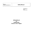
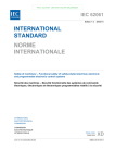
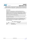
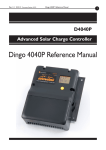
STMicroelectronics product development process, compliant with the ISO/TS 16949
standard, is a set of interrelated activities dedicated to transform customer specification and
market or industry domain requirements into a semiconductor device and all its associated
elements (package, module, sub-system, application, hardware, software and
documentation), qualified respecting ST internal procedures and able to be manufactured
using ST internal or subcontracted technologies.
Figure 1. STMicroelectronics product development process
&RQFHSWLRQ
u.H\FKDUDFWHULVWLFVDQG
UHTXLUHPHQWVUHODWHGWRIXWXUH
XVHVRIWKHGHYLFH
u,QGXVWU\GRPDLQVVSHFLILF
FXVWRPHUUHTXLUHPHQWVDQG
GHILQLWLRQRIFRQWUROVDQGWHVWV
QHHGHGIRUFRPSOLDQFH
u3URGXFWWDUJHWVSHFLILFDWLRQ
DQGVWUDWHJ\
u3URMHFWPDQDJHUDSSRLQWPHQW
WRGULYHSURGXFWGHYHORSPHQW
u(YDOXDWLRQRIWKH
WHFKQRORJLHVGHVLJQWRROV
DQG,3VWREHXVHG
u'HVLJQREMHFWLYHVSHFLILFDWLRQ
DQGSURGXFWYDOLGDWLRQ
VWUDWHJ\
u'HVLJQIRUTXDOLW\WHFKQLTXHV
')'')7')5')0«
GHILQLWLRQ
u$UFKLWHFWXUHDQGSRVLWLRQLQJ
WRPDNHVXUHWKHVRIWZDUH
DQGKDUGZDUHV\VWHP
VROXWLRQVPHHWWKHWDUJHW
VSHFLILFDWLRQ
u3URGXFWDSSURYDOVWUDWHJ\
DQGSURMHFWSODQ
'HVLJQ
YDOLGDWLRQ
u6HPLFRQGXFWRUGHVLJQ
GHYHORSPHQW
u+DUGZDUHDQGDSSOLFDWLRQ
GHYHORSPHQW
u6RIWZDUHGHYHORSPHQW
u$QDO\VLVRIQHZSURGXFW
VSHFLILFDWLRQWRIRUHFDVW
UHOLDELOLW\SHUIRUPDQFH
u5HOLDELOLW\SODQUHOLDELOLW\
GHVLJQUXOHVSUHGLFWLRQRI
IDLOXUHUDWHVIRURSHUDWLQJOLIH
WHVWXVLQJ$UUKHQLXV¶VODZDQG
RWKHUDSSOLFDEOHPRGHOV
u8VHRIWRROVDQG
PHWKRGRORJLHVVXFKDV
$343')0')7')0($
)0.0
u'HWHFWLRQRISRWHQWLDO
UHOLDELOLW\LVVXHVDQGVROXWLRQ
WRRYHUFRPHWKHP
u$VVHVVPHQWRI(QJLQHHULQJ
6DPSOHV(6WRLGHQWLI\WKH
PDLQSRWHQWLDOIDLOXUH
PHFKDQLVPV
u6WDWLVWLFDODQDO\VLVRI
HOHFWULFDOSDUDPHWHUGULIWVIRU
HDUO\ZDUQLQJLQFDVHRIIDVW
SDUDPHWULFGHJUDGDWLRQVXFK
DVUHWHQWLRQWHVWV
u)DLOXUHDQDO\VLVRQIDLOHG
SDUWVWRFODULI\IDLOXUHPRGHV
DQGPHFKDQLVPVDQGLGHQWLI\
WKHURRWFDXVHV
u3K\VLFDOGHVWUXFWLYHDQDO\VLV
RQJRRGSDUWVDIWHUUHOLDELOLW\
WHVWVZKHQUHTXLUHG
u(OHFWURVWDWLFGLVFKDUJH(6'
DQGODWFKXSVHQVLWLYLW\
PHDVXUHPHQW
4XDOLILFDWLRQ
u6XFFHVVIXOFRPSOHWLRQRI
WKHSURGXFWTXDOLILFDWLRQ
SODQ
u6HFXUHSURGXFWGHOLYHULHV
RQDGYDQFHGWHFKQRORJLHV
XVLQJVWUHVVPHWKRGRORJLHV
WRGHWHFWSRWHQWLDOZHDN
SDUWV
u6XFFHVVIXOFRPSOHWLRQRI
HOHFWULFDOFKDUDFWHUL]DWLRQ
u*OREDOHYDOXDWLRQRIQHZ
SURGXFWSHUIRUPDQFHWR
JXDUDQWHHUHOLDELOLW\RI
FXVWRPHUPDQXIDFWXULQJ
SURFHVVDQGILQDODSSOLFDWLRQ
RIXVHPLVVLRQSURILOH
u)LQDOGLVSRVLWLRQIRUSURGXFW
WHVWFRQWURODQGPRQLWRULQJ
069
DocID027264 Rev 2
11/92
91
STM32F3 series microcontrollers development process
2.2
UM1846
Yogitech fRMethodology process
Yogitech fRMethodology is the “white-box” approach for safety design exploration
proprietary of Yogitech, including tools and methodology to FMEA/FTA analysis and fault
injection of integrated circuits. Appendix A: Overview of fRMethodology reports additional
information.
Yogitech contribution to IEC 61508 compliance of STMicroelectronics development process
can be summarized in these key elements:
Failure rate estimation based on multiple industry standards as well as
STMicroelectronics manufacturing data,
Application of Yogitech fault injection techniques/tools to validate the safety metrics
claimed for STMicroelectronics devices belonging to STM32 program.
12/92
DocID027264 Rev 2
UM1846
Reference safety architecture
3
Reference safety architecture
3.1
Introduction
The STM32F3 series microcontrollers described in this document is a Safety Element out of
Context (SEooC), that is, the intent is to describe a compliant item that can be used within
different safety applications.
The aim of this section is to identify such compliant item and therefore to define the context
of the analysis in terms of assumptions with respect to a reference concept definition, that is
with respect to reference safety requirements as also assumptions with respect to the
design external to that compliant item.
As a consequence of the SEooC approach, the goal is not to provide an exhaustive hazard
and risk analysis of the system around the microcontroller, but rather to list the systemrelated information - such as the application-related assumptions for dangerousness
factors, frequency of failures and diagnostic coverage already guaranteed by the application
- that have been considered during the following steps of the analysis.
Additional details on the reference safety architecture are given in Appendix B: Examples of
safety architectures – Informative.
3.2
Compliant item
3.2.1
Definition of the compliant item
According to IEC 61508:1 clause 8.2.12, a compliant item is any item (for example an
element) on which a claim is being made with respect to the clauses of IEC 61508 series.
With respect to its user, at the end of its development the compliant item shall be described
by a safety manual.
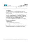
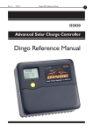
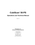
In this document, the compliant item is defined as a system including one or two STM32
microcontrollers (MCU) (see Figure 2). The communication bus is directly or indirectly
connected to sensors and actuators.
Figure 2. Definition of the compliant item
069
Other components might be related to the compliant item, like the external HW components
needed to guarantee either the functionality of the STM32F3 (external memory, clock quartz
etc) or its safety (for example the external watchdog, voltage supervisors).
DocID027264 Rev 2
13/92
91
Reference safety architecture
3.2.2
UM1846
Safety functions performed by the compliant item
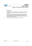
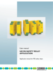
In essence, the compliant item architecture can be represented as composed by the
following processes performing the safety function or part of it:
Input processing elements (PEi) reading safety related data from the remote controller
connected to the sensor(s) and transferring them to the following computation
elements;
Computation processing elements (PEc) performing the algorithm required by the
safety function and transferring the results to the following output elements;
Output processing elements (PEo) transferring safety related data to the remote
controller connected to the actuator;
in the case of the 1oo2, 1oo2d or 2oo2 architecture (see Appendix B: Examples of
safety architectures – Informative), a further voting processing element (PEv) can be
present;
in the 1oo2d case (see again Appendix B: Examples of safety architectures –
Informative), the abstract view is the same as 1oo2 but with the addition of diagnostic
processing elements (PEd), having the role of performing cross-diagnostic functions
and contributing to the decision of the voter PEv;
processes external to the compliant item are considered to guarantee functional safety,
such as a watchdog (WDTe) and voltage monitors (VMONe).
Figure 3. Abstract view of compliant item functions
069
The role of the PEv and of the external processes WDTe and VMONe is clarified in the
sections where the CoU (definition of safety mechanism) are detailed:
WDTe: refer to Independent watchdog – VSUP_SM_2, Control flow monitoring in
application software – CPU_SM_1,
VMONe: refer to Supply Voltage Monitoring – VSUP_SM_1.
14/92
DocID027264 Rev 2
UM1846
Reference safety architecture
3.3
Assumed requirements
3.3.1
Assumed safety requirements
It is assumed that the concept specification, the hazard and risk analysis, the overall safety
requirement specification and the consequent allocation has determined the following
requirements for the compliant item (assumed safety requirements):
The compliant item can be used for four kinds of safety functions:
–
A continuous mode / high-demand SIL3 safety function (CM3), or
–
A low-demand SIL3 safety function (LD3), or
–
A continuous mode / high-demand SIL2 safety function (CM2), or
–
A low-demand SIL2 safety function (LD2).
The compliant item is used in a safety function with a worst case budget of 10 msec for
the STM32 MCU to detect and react to a failure, which corresponds to the portion of
the Process Safety Time(a) allocated to the STM32F3 MCU (“STM32F3 duty” in
Figure 4)
Figure 4. Allocation and target for STM32 PST
(QG8VHUGXW\
0&8GHWHFWLRQ
6700&8GXW\
):UHDFWLRQ
6:UHDFWLRQ
«
$FWXDWRUUHDFWLRQ
6\VWHPOHYHO367
06Y9
The compliant item is used in a safety function powered-on for a long time. It is
assumed to not require any proof test and the lifetime of the product is considered to be
not less than 10 years.
The safe state of the compliant item is the one in which either:
–
the operating system (OS) is informed by the presence of a fault and a reaction is
possible, or
–
if the OS cannot be informed or the OS is not able to execute a reaction(b):
in case of a 1oo2 or 1oo2D architecture, the PEv shall be directly informed so that
the PEv itself is able to achieve or maintain the safe state of the system or,
in case of 1oo1 and 1oo2/1oo2D high demand or continuous mode architectures,
the safe state of the electronic system is “de-energize”.
The compliant item is assumed to be analyzed according to routes 1H and 1S of IEC
61508:2.
a. As explained in the following section, for the HFT=1 computations the value of the process safety time is not as
stringent as it is for HFT=0 architectures (that is clarified further in the document).
b. The end user shall take into account that hardware random failures affecting the STM32 can compromise the
MCU capability of operating properly (for example failure modes affecting the program counter prevent the
correct execution of software).
DocID027264 Rev 2
15/92
91
Reference safety architecture
UM1846
The base assumptions about the de-energize state and the repair conditions, in the
computation of the PFD/PFH, are as follows;
In the 1oo1 mode:
–
The system is de-energized as soon as a fault is identified by the HW or SW
diagnostics.
–
If the fault has been identified as a transient fault, the compliant item can be reset
and the safety function can continue after reset.
–
If the fault has been identified as a permanent fault or if it has not been identified,
the compliant item is assumed to be kept de-energized.
In the 1oo2 / 1oo2D low-demand modes:
–
The 1oo2 system is NOT de-energized if a fault is identified in one of the two
channels.
–
The faulty compliant item can be repaired, that is the faulty STM32F3 MCU can be
replaced or one of the external components might be replaced.
In the 1oo2 / 1oo2D high-demand or continuous modes:
–
The system is de-energized as soon as a fault is identified in one of the two
channels or in the shared logic.
–
If the fault has been identified as a transient fault, the compliant item can be reset
and the safety function can continue after reset.
–
If the fault has been identified as a permanent fault or if it has not been identified,
the compliant item is assumed to be kept de-energized, and the compliant item
cannot be repaired, that is the faulty STM32F3 MCU cannot be replaced or one of
the external components cannot be replaced.
3.4
Electrical specifications and environment limits
The user must not exceed the electrical specification and the environmental limits defined in
the below list as reported in the STM32F3 user manual in order to guarantee the STM32F3
safety integrity:
Absolute maximum rating,
Capacity,
Operating conditions.
Due to the large number of STM32F3 part numbers, the related user manuals/datasheets
are not listed in this document; users are responsible to carefully check the above reported
limits in the technical documentation on the related part number available on www.st.com.
16/92
DocID027264 Rev 2
UM1846
3.5
Reference safety architecture
Systematic safety integrity
According to the requirements of IEC 61508 -2, 7.4.2.2, the Route 1s has been considered
in the STM32F3 development and the techniques and measures given in IEC 61508-2
Annex F have been applied. The Safety Case Database (Section 5: List of evidences)
maintains the evidences of the compliance to the norm.
3.6
Description of hardware and software diagnostics
This section lists all the safety mechanisms (hardware, software and application level)
considered in the safety analysis of the microcontrollers of the STM32F3 series. It is
expected that users are familiar with the STM32F3 architecture, and that this document is
used in conjunction with the related device datasheet, user manual and reference
information. Therefore, to avoid the eventuality of mistakes and reduce the amount of
information to be shown, no functional details are included in this document.
Note that the part numbers of the STM32F3 series represent different combinations of
peripherals (for instance, some of them are not equipped with USB peripheral). To reduce
the number of documents and avoid information-less repetitions, the current safety manual
(and therefore this section) addresses the overall possible peripherals available in the
targeted part numbers. Users have to select which peripherals are really available on their
devices, and discard the meaningless recommendations accordingly.
The implementation guidelines reported in the following section are for reference only. The
safety verification executed by Yogitech and related coverage figures reported in this
manual are based on such guidelines.
Please read the following definitions:
end user: the final user of STM32F3 that is in charge of integrating the MCU in a real
application (for example an electronic control board).
application software: the real software that runs on the STM32F3 and that is used to
implement the safety function.
3.6.1
Cortex®-M4 CPU
Periodical core self-test software - CPU_SM_0
Permanent faults affecting the CPU Core ARM® Cortex®-M4 (including also the FPU) are
addressed through a dedicated software test executing a sequence of instructions and data
transfers.
The software test is built around well-known techniques already addressed by IEC 61508:7,
A.3.2 (Self-test by software: walking bit one-channel). A detailed safety analysis has shown
that a self-test software based only on software testing operation is not able to reach the
required values of coverage due to the complexity of the CPU. Therefore, in order to reach
the required values of coverage, the self-test software has to be specified by means of a
detailed analysis of all the CPU failure modes and related failure modes distribution.
Moreover, it has to be verified by means of fault injection (according to ISO 26262:10,
Annex A - the state of the art in terms of safety analysis applied to integrated circuits - fault
injection is the recommended method for the verification of failure modes coverage in
modern and complex microprocessor like Cortex®-M4).
DocID027264 Rev 2
17/92
91
Reference safety architecture
UM1846
The overall test software suite is assumed to be periodically executed with a time period
compatible with the IEC 61508 requirements for the relationship between PST and the
diagnostic test interval.
Control flow monitoring in application software – CPU_SM_1
A significant part of the failure distribution of ARM® Cortex®-M4 core for permanent faults is
related to failure modes directly related to program counter loss of control or hang-up. Due
to their intrinsic nature, such failure modes are not addressed by a standard software test
method based on the execution of sequences of instruction/data access and consequent
checks. Therefore it is necessary to implement a run-time control of the application software
flow, in order to monitor and detect deviation from the expected behavior due to such faults.
Linking this mechanism to watchdog firing assures that severe loss of control (or, in the
worst case, a program counter hang-up) will be detected within DTI.
This diagnostic measure also contributes to the transient fault detection affecting the
program counter and branch execution subpart in ARM® Cortex®-M4.
The guidelines for the implementation of the method are the following:
The different internal states of the application software is well documented and
described (the use of a dynamic state transition graph is encouraged).
The monitoring of the correctness of each transition between different states of the
application software is implemented.
The transition through all expected states during the normal application software
program loop is checked.
The function in charge of triggering the system watchdog is implemented in order to
constrain the triggering (preventing the watchdog reset) also to the correct execution of
the above-described method for program flow monitoring.
The use of the window feature of the independent watchdog (IWDG) (or an external one)
helps to implement a more robust control flow mechanism fed by a different clock source. In
any case the safety metrics do not depend on the watchdog in use (the adoption of
independent or external watchdog contributes to the mitigation of dependent failures, see
Section 4.2.2: Clock).
Double computation in application software – CPU_SM_2
A timing redundancy for safety-related computation is considered to detect transient faults
affecting the ARM® Cortex®-M4 CPU subparts (including therefore the FPU, if used for
safety-relevant computations) devoted to mathematical computations and data access.
The guidelines for the implementation of the method are the following:
The requirement needs be applied only to safety-relevant computation, that is to the
computations that in case of wrong result could interfere with the system safety
18/92
DocID027264 Rev 2
UM1846
Reference safety architecture
functions. Such computation shall be therefore carefully identified in the original
application software source code.
Both mathematical operation and comparison are intended as computation.
The redundant computation for comparison could be implemented according to the
following template:
–
Original code:
If (VarA > VarB) then { ( execute function) }
–
Modified code:
copyVarA:=VarA;
copyVarB:=VarB;
If (VarA > VarB) then {
If (copyVarA <= copyVarB) then { (signal_error); break }
( execute function)
}
The redundant computation for mathematical computation is implemented by using
copies of the original data for second computation, and by using an equivalent formula
if possible.
End users are responsible to carefully avoid that the intervention of optimization
features of the used compiler removes the timing redundancy introduced according to
this current condition of use.
ARM® Cortex®-M4 HardFault exceptions – CPU_SM_4
HardFault exception raise is an intrinsic safety mechanism implemented in ARM® Cortex®M4 core, mainly devoted to intercept systematic faults due to software limitations and/or
error in software design, leading for example to execution of undefined operations,
unaligned address access. This safety mechanism is therefore able to detect hardware
random faults inside the CPU bringing to such described abnormal operations.
Stack hardening for application software – CPU_SM_4
The stack hardening method is required to address faults affecting the CPU register bank.
This method is based on source code modification, introducing information redundancy in
register-passed information to the called functions.
The guidelines for the implementation of the method are the following:
Pass also the redundant copy of the passed parameters values (possibly inverted) and
execute a coherence check in the function.
Pass also the redundant copy of the passed pointers and execute a coherence check
in the function.
For the parameters that are not protected by redundancy, implement defensive
programming techniques (plausibility check of passed values). For example
enumerated fields are to be checked for consistency.
External watchdog – CPU_SM_5
Using an external watchdog for the control flow monitoring method (CPU_SM_1)
contributes to further reduce potential common cause failures, because the external
watchdog will be clocked and supplied independently from the STM32F3.
DocID027264 Rev 2
19/92
91
Reference safety architecture
UM1846
MPU detection of illegal memory access - CPU_SM_6
The MPU can be programmed by end users to achieve memory space separation between
different software running on the CPU. For this reason, MPU programming is highly
recommended to achieve software robustness in terms of systematic capability.
The MPU is able to detect illegal memory access due not to software design errors but to
hardware faults affecting program counter and/or CPU data interfaces. Therefore it
contributes also to address both permanent and transient faults affecting CPU core.
3.6.2
System FLASH memory
Periodical software test for Flash memory – FLASH_SM_0
Permanent faults affecting the system Flash memory (that is the memory cells and address
decoder) are addressed through a dedicated software test that checks the memory cell
contents versus the expected value, using signature-based techniques. According to IEC
61508:2 Table A.5, the effective diagnostic coverage of such techniques depends on the
width of the signature in relation to the block length of the information to be protected therefore the signature computation method is to be carefully selected. Note that the simple
signature method (IEC 61508:7 - A.4.2 Modified checksum) is inadequate as it only
achieves a low value of coverage.
The information block does not need to be addressed with this test as it is not used during
normal operation (no data/program fetch).
Without information over the frequency of usage of different occupied Flash sections, in
principle, all used Flash area are assumed to be tested with a time period compatible with
the IEC 61508 requirements for the relationship between PST and the diagnostic test
interval.
Control flow monitoring in application software – FLASH_SM_1
Permanent and transient faults affecting the system Flash memory (that is the memory cells
and address decoder) can interfere with the access operation by the CPU, leading to wrong
data or instruction fetches. Such wrong data and operation, if able to heavily interfere with
the expected flow of the application software, are detected by strong control flow
mechanism linked to a system watchdog. For more detailed implementation guidelines for
such technique refer to safety mechanism CPU_SM_1 in Control flow monitoring in
application software – CPU_SM_1.
ARM® Cortex®-M4 Hardfault exceptions – FLASH_SM_2
Hardfault exception raise is an intrinsic safety mechanism implemented in ARM® Cortex®M4 core, mainly devoted to intercept systematic faults that are due to software limitations
and/or error in software design, leading for example to the execution of undefined
operations, unaligned address access. This safety mechanism is therefore able to detect
hardware random faults (both permanent and transient) that affect the system Flash
memory (cells and address decoder) bringing to such described abnormal operations.
Option byte write protection – FLASH_SM_3
This safety mechanism prevents unintended writes on the option byte; it addresses
therefore systematic faults in software application and not hardware random faults affecting
the option byte value during running time. The use of this method is encouraged to enhance
end application robustness for systematic faults.
20/92
DocID027264 Rev 2
UM1846
3.6.3
Reference safety architecture
System SRAM memory
Periodical software test for SRAM memory – RAM_SM_0
To address permanent faults affecting SRAM data cells and the address decoder it is
required to execute a periodical software test on the system RAM memory. The selection of
the algorithm ensures the target SFF coverage for both the RAM cells and the address
decoder. The end user provides also evidences of the effectiveness of the coverage of the
selected method.
The overall test software suite is assumed to be periodically executed with a time period
compatible with the IEC 61508 requirements for the relationship between PST and the
diagnostic test interval.
Stack hardening for application software – RAM_SM_1
The stack hardening method is used to enhance the application software robustness to
SRAM faults that affect the address decoder. The method is based on source code
modification, introducing information redundancy in the stack-passed information to the
called functions. This method is relevant in case the combination between the final
application software structure and the compiler settings requires a significant use of the
stack for passing function parameters.
The guidelines for the implementation of the method are the following:
Pass also the redundant copy of the passed parameters values (possibly inverted) and
execute a coherence check in the function.
Pass also the redundant copy of the passed pointers and execute a coherence check
in the function.
For parameters that are not protected by redundancy, implement defensive
programming techniques such as the plausibility check of the passed values for
example to check the consistency of enumerated fields.
Information redundancy for safety-related variables in application software –
RAM_SM_2
To address transient faults affecting SRAM controller, it is required to implement information
redundancy on the safety-related system variables stored in the RAM.
The guidelines for the implementation of this method are the following:
The system variables that are safety-related (in the sense that a wrong value due to a
failure in reading on the RAM affects the safety functions) are well-identified and
documented.
The arithmetic computation and/or decision based on such variables are/is executed
twice and the two final results are compared.
Note that the implementation of this safety method shows a partial overlap with an already
foreseen method for Cortex®-M4 (CPU_SM_1); optimizations in implementing both
methods are therefore possible (see Control flow monitoring in application software –
CPU_SM_1).
DocID027264 Rev 2
21/92
91
Reference safety architecture
UM1846
Parity bit check - RAM_SM_3
The Parity check on system SRAM gives a relevant contribution to detection of hardware
random faults (both permanent and transient) affecting RAM data cells (no expected
contribution is expected for address decoder faults detection). This option is assumed to be
enabled by the user after the boot.
3.6.4
System bus interconnect
Periodical software test for interconnections – BUS_SM_0
The intra-chip connection resources (Bus Matrix, AHB/APB bridges) need to be periodically
tested for permanent faults detection. Note that STM32F3 series microcontrollers have no
hardware safety mechanism to protect these structures. The test executes a connectivity
test of these shared resources, including the testing of the arbitration mechanisms between
peripherals. This method which is based on the periodical execution of software-based tests
is executed at least once per DTI.
According to IEC 61508:2 Table A.8, A.7.4 the above-described method is considered able
to achieve high levels of coverage (and it has to be verified by means of fault injection).
Information redundancy in intra-chip data exchanges – BUS_SM_1
Both permanent and transient fault affecting the intra-chip connection features (Bus Matrix,
AHB/APB bridges) are addressed by information redundancy techniques implemented over
the messages exchanged inside the MCU.
Lock mechanism for configuration options – LOCK_SM_0
The STM32F3 series microcontrollers feature spread protection to prevent unintended
configuration changes for some peripherals and system registers (for example GPIO locking
system); the spread protection detects systematic faults in software application and
transient faults such as soft errors, that cause some bit-flip on registers during running time.
The use of this method is encouraged to enhance the end application robustness to
systematic faults.
The method described in this section provides a marginal protection against permanent and
transient faults affecting system interconnect bus.
3.6.5
Flexible Static Memory Controller (FSMC)
Control flow monitoring in application software - FSMC_SM_0
If FSMC is used to connect an external memory containing software code to be executed by
the CPU, permanent and transient faults affecting the FSMC memory controller are able to
interfere with the access operation by the CPU, leading to wrong data or instruction fetches.
The strong control flow mechanism linked to a system watchdog is able to detect such
failures, in case they interfere with the expected flow of the application software.
For more detailed implementation guidelines for such technique refer to safety mechanism
CPU_SM_1.
22/92
DocID027264 Rev 2
UM1846
Reference safety architecture
Information redundancy - FSMC_SM_1
If FSMC is used to connect an external memory where safety-relevant data is stored,
information redundancy techniques for stored data are able to address faults affecting the
FSMC interface. The possible techniques are:
To use redundant copies of safety relevant data and perform coherence check before
use.
To organize data in arrays and compute the checksum field to be checked before use.
Note:
The above-mentioned safety mechanisms are addressing the FSMC interface included in
STM32 MCU. No claims are reported here about the addressing of hardware random faults
affecting the external memory connected to FSMC.
3.6.6
NVIC and EXTI controller
Periodical read-back of configuration registers – NVIC_SM_0
This diagnostic measure that is typically referred to as “Read Back Periodic by Software of
Configuration Registers” is implemented by executing a periodical check of the
configuration registers of each used system peripheral against its expected value that was
previously stored in RAM and adequately updated after each configuration change. It mainly
addresses the transient faults that affect the configuration registers, by detecting bit flips in
the registers due to these transient faults. The register test is executed at least once per DTI
in order to be able to claim the related diagnostic coverage.
Expected and unexpected interrupt check – NVIC_SM_1
According to IEC 61508:2 Table A.1 recommendations, a diagnostic measure for
continuous, absence or cross-over of interrupt must be implemented. The method of
expected and unexpected interrupt check is implemented at application software level. It
contributes to detecting both permanent and transient fault for all the above-reported failure
modes affecting interrupt handling.
The guidelines for the implementation of the method are the following:
The list of the implemented interrupt for the MCU is well documented, reporting also
the expected frequency of each request when possible (for example the interrupts
related to ADC conversion completion, therefore coming on a deterministic way).
Individual counters are maintained for each interrupt request served, in order to detect
in a given time frame the cases of a) no interrupt at all b) too many interrupt requests
(“babbling idiot” interrupt source). The control of the time frame duration shall be
regulated according to the individual interrupt expected frequency.
Interrupt vectors related to unused interrupt source point to a default handler that will
report, in case of triggering, a faulty condition (unexpected interrupt).
In case an interrupt service routine is shared between different sources, a plausibility
check on the caller identity is implemented.
Interrupt requests related to not-safety-relevant peripherals are handled with the same
method here described, despite their originator safety classification; in order to
decrease the complexity of this method implementation, the use of polling instead of
interrupt for not-safety-relevant peripherals is suggested.
DocID027264 Rev 2
23/92
91
Reference safety architecture
3.6.7
UM1846
DMA
Periodical read-back of configuration registers – DMA_SM_0
This diagnostic measure that is typically referred to as “Read Back Periodic by Software of
Configuration Registers” is implemented by executing a periodical check of the
configuration registers of the DMA peripheral against its expected value that was previously
stored in RAM and adequately updated after each configuration change. It mainly
addresses the transient faults that affect the configuration registers, by detecting bit flips in
the registers due to these transient faults. The register test is executed at least once per DTI
in order to be able to claim the related diagnostic coverage.
Information redundancy on data packet transferred via DMA – DMA_SM_1
The information redundancy required on the DMA data transfer cannot be implemented, in
line with the DMA concept, with multiple transfers of the same data block. Therefore, this
method is implemented by constraining the use of DMA to the transfer of data packed
covered by a redundancy check (like CRC, or similar techniques). Note that other diagnostic
measures on data communication peripherals (potential DMA sources or destinations)
already foresee the implementation of information redundancy at message level – therefore
the overlap with those measures could reduce the potential complexity in the referredmethod implementation.
Information redundancy including sender/receiver identifier on data packet
transferred via DMA – DMA_SM_2
This method requires that the information redundancy introduced at message level
(therefore adding a checksum field to the message) helps to identify inside the MCU the
source and the originator of the message exchange (that is which peripherals dialogs with
the RAM or the CPU). This is implemented by adding an additional field to the protected
message, with a coding convention for message type identification fixed at MCU level. That
is, this method implements some “virtual channel” between the peripheral and the target.
Periodical software test for DMA – DMA_SM_3
This method requires the periodical testing of the DMA basic functionality, implemented
through a deterministic transfer of a data packet from one source to another (for example
from memory to memory) and the checking of the correct transfer of the message on the
target. The data packets are composed by not-trivial patterns (avoid the use of 0x0000,
0xFFFF values) and organized in order to allow the detection during the check of the
following failures:
Incomplete packed transfer,
Errors in single transferred word,
Wrong order in packed transmitted data.
The use of CRC packet protection is a way to simplify such checking operations.
3.6.8
CAN1/2
Periodical read-back of configuration registers – CAN_SM_0
This diagnostic measure that is typically referred to as “Read Back Periodic by Software of
Configuration Registers” executes a periodical check of the configuration registers of CAN
peripheral against its expected value that is previously stored in the RAM and adequately
24/92
DocID027264 Rev 2
UM1846
Reference safety architecture
updated after each configuration change. It mainly addresses the transient faults affecting
the configuration registers, detecting bit flips in the registers due to transient faults. The
register test is executed at least once per DTI in order to be able to claim the related
diagnostic coverage.
Protocol error signals – CAN_SM_1
The CAN protocol error counters, which are entirely managed by the module at hardware
level despite being conceived to detect network-related abnormal conditions, are able to
contribute to the detection of the faults that lead to error messages generation.
The handling at application level of such error signals is a common technique in embedded
applications. Their use is highly recommended.
Information redundancy techniques on messages, including End to End
safing – CAN_SM_2
The CAN communications are protected by addressing both the permanent and transient
faults with the redundant information technique that includes the End to End Safing.
For the implementation of redundant information, it is possible to adopt a different approach:
Multiple sending of the same message, with comparison of the received results.
Addition by the sender of a checksum field to the message to be verified by the
receiver.
In case the checksum field approach is adopted, the selection of the algorithm for checksum
computation shall ensure a similar protection against message corruption as the one
ensured by a full redundancy.
For End to End Safing, additional measures are implemented:
Additional field in payload allowing the unique identification of sender/receiver, and
coherence check by receiver side.
Timing monitoring of the message exchange (for example check the message arrival
within the expected time window)
Check of the message consistence using a message counter in the additional payload
field and checking the right sequence of messages on the receiver side.
The use of a safe communication protocol such as ProfiSAFE is recommended for the
correct implementation of this safety mechanism.
3.6.9
HDMI CEC module
Periodical read-back of configuration registers - HDMI_SM_0
This diagnostic measure that is typically referred to as “Read Back Periodic by Software of
Configuration Registers” executes a periodical check of the configuration registers of HDMI
module against their expected value that was previously stored in RAM and adequately
updated after each configuration change. It mainly addresses the transient faults affecting
the configuration registers, detecting bit flips in the registers due to transient faults. The
registers test is executed at least once per DTI in order to be able to claim the related
diagnostic coverage.
DocID027264 Rev 2
25/92
91
Reference safety architecture
UM1846
Protocol error signals - HDMI_SM_1
HDMI protocol errors signals, despite being conceived to detect physical layer related
abnormal conditions, are able to contribute to the detection to faults leading to error
messages generation, for instance reception, transmission and arbitration error flags,
transmission and reception under-run.
Information redundancy techniques on messages - HDMI_SM_2
The redundant information technique is used to protect the HDMI communications by
detecting both the permanent and transient faults. There are two different approaches to
implement this method:
Multiple sending of the same message, with comparison of the received results,
Addition by the sender of a checksum field to the message to be verified by the
receiver.
In case the checksum field approach is adopted, the selection of the algorithm for checksum
computation shall ensure a similar protection against message corruption as the one
ensured by a full redundancy. Theoretic demonstrations on coverage capability are
admitted; the use of CRC coding is anyway suggested (also looking into the availability of a
quick hardware support on the MCU platform).
The above-reported approaches are equivalent; an additional criteria for the selection is the
evaluation of the computation capability of the external device with which the STM32F3
series microcontrollers will exchange data.
3.6.10
USART 1/2/3/4/5
Periodical read-back of configuration registers – UART_SM_0
This diagnostic measure that is typically referred to as “Read Back Periodic by Software of
Configuration Registers” executes a periodical check of the configuration registers of
USART against their expected value (previously stored in RAM and adequately updated
after each configuration change). It mainly addresses transient faults affecting the
configuration registers, detecting bit flips in the registers due to transient faults. The
registers test is executed at least once per DTI in order to be able to claim the related
diagnostic coverage.
Protocol error signals – UART_SM_1
The UART protocol errors signals (if used) despite being conceived to detect physical layer
related abnormal conditions, are able to contribute to the detection to faults leading to error
messages generation. For instance, option parity bit in data byte frame, overrun error.
The handling at application level of such error signals is a common technique in embedded
applications. Their use is highly recommended.
Information redundancy techniques on messages – UART_SM_2
The redundant information technique is used to protect the USART communications by
detecting both the permanent and transient faults. There are two different approaches to
implement this technique:
Multiple sending of the same message, with comparison of the received results.
Addition by the sender of a checksum field to the message to be verified by the
receiver.
26/92
DocID027264 Rev 2
UM1846
Reference safety architecture
In case the checksum field approach is adopted, the selection of the algorithm for checksum
computation shall ensure a similar protection against message corruption as the one
ensured by a full redundancy. Theoretic demonstrations on coverage capability are admitted
– the use of CRC coding is anyway suggested.
The above-reported approaches are equivalent; an additional criterion for the selection of
the approach is the availability of a quick hardware support on the MCU platform, and the
evaluation of the computation capability of the external device with which the STM32F3
series microcontrollers will exchange data.
Note that if the message is transferred by the DMA, the implementation of this safety
mechanism takes into account also the overlap of DMA-related safety mechanism related to
the message exchange inside the MCU and already declared as highly recommended.
3.6.11
I2C 1/2/3
Periodical read-back of configuration registers – IIC_SM_0
This diagnostic measure that is typically referred to as “Read Back Periodic by Software of
Configuration Registers” executes a periodical check of the configuration registers of I2C
against their expected value (previously stored in RAM and adequately updated after each
configuration change). It mainly addresses transient faults affecting the configuration
registers, detecting bit flips in the registers due to transient faults. The registers test is
executed at least once per DTI in order to be able to claim the related diagnostic coverage.
Protocol error signals – IIC_SM_1
The I2C protocol errors signals, despite being conceived to detect physical layer related
abnormal conditions, are able to contribute to the detection of faults leading to error
messages generation such as for instance the ACK assertion phase, and related checks.
The handling at application level of such error signals being a common technique in
embedded applications, their use is highly recommended.
Note:
the adoption of SMBus protocol, if available on the selected I2C module and compatible with
the external connected devices, is a way to get available additional hardware-based error
checking mechanisms.
Information redundancy techniques on messages – IIC_SM_2
The redundant information technique is used to protect the I2C communications by
detecting both the permanent and transient faults. There are two different approaches to
implement this method:
Multiple sending of the same message, with comparison of the received results
Addition by the sender of a checksum field to the message to be verified by the
receiver.
In case the checksum field approach is adopted, the selection of the algorithm for checksum
computation shall ensure a similar protection against message corruption as the one
ensured by a full redundancy. Theoretic demonstrations on coverage capability are admitted
– the use of CRC coding is anyway suggested (also looking to the availability of a quick
hardware support on the MCU platform).
The above-reported approaches are equivalent; an additional criterion for the selection is
the evaluation of the computation capability of the external device with which the STM32F3
series microcontrollers will exchange data.
DocID027264 Rev 2
27/92
91
Reference safety architecture
UM1846
If the message is transferred by the DMA, the implementation of this safety mechanism
takes into account also the overlap of DMA-related safety mechanism related to the
message exchange inside the MCU and therefore its use is highly recommended.
Note:
The adoption of SMBus protocol (if available on selected I2C module and compatible with
the external connected devices) is a way to simplify the implementation of this safety
mechanism.
3.6.12
SPI 1/2/3
Periodical read-back of configuration registers – SPI_SM_0
This diagnostic measure that is typically referred to as “Read Back Periodic by Software of
Configuration Registers” executes a periodical check of the configuration registers of SPI
against their expected value that was previously stored in RAM and adequately updated
after each configuration change. It mainly addresses transient faults affecting the
configuration registers, detecting bit flips in the registers due to transient faults. The
registers test is executed at least once per DTI in order to be able to claim the related
diagnostic coverage.
Protocol error signals - SPI_SM_1
The SPI protocol errors signals, despite being conceived to detect physical layer related
abnormal conditions, are able to contribute to the detection to faults leading to error
messages generation such as for instance FIFO overrun and Mode error flags.
The handling at application level of such error signals being a common technique in
embedded applications, their use is highly recommended.
Information redundancy techniques on messages – SPI_SM_2
The redundant information technique is used to protect the SPI communications by
detecting both the permanent and transient faults. There are two different approaches to
implement this method:
Multiple sending of the same message, with comparison of the received results.
Addition by the sender of a checksum field to the message to be verified by the
receiver.
In case the checksum field approach is adopted, the selection of the algorithm for checksum
computation shall ensure a similar protection against message corruption as the one
ensured by a full redundancy. Theoretic demonstrations on coverage capability are admitted
– the use of the hardware CRC computation unit built into SPI module is highly suggested).
The above-reported approaches are equivalent; an additional criterion for the selection is
the evaluation of the computation capability of the external device with which the STM32F3
series microcontrollers will exchange data.
If the message is transferred by the DMA, the implementation of this safety mechanism
takes into account also the overlap of DMA-related safety mechanism related to the
message exchange inside the MCU and therefore its use is highly recommended.
28/92
DocID027264 Rev 2
UM1846
3.6.13
Reference safety architecture
USB - 2.0 Universal Serial Bus interface HS/FS modules
Periodical read-back of configuration registers – USB_SM_0
This diagnostic measure that is typically referred to as “Read Back Periodic by Software of
Configuration Registers” executes a periodical check of the configuration registers of USB
against their expected value that was previously stored in the RAM and adequately updated
after each configuration change. It mainly addresses transient faults affecting the
configuration registers, detecting bit flips in the registers due to transient faults. The
registers test is executed at least once per DTI in order to be able to claim the related
diagnostic coverage.
Protocol error signals – USB_SM_1
The USB protocol errors signals, despite being conceived to detect physical layer related
abnormal conditions, are able to contribute to the detection to faults leading to error
messages generation. The errors are those entirely handled by hardware buffer overruns,
bit stuffing, frame format violations, CRC errors. End users must take care of the system
availability by managing adequately the protocol errors that are not related to random
hardware faults but to transmission issues that can be recovered with a repetition of the
message transmission.
The handling at application level of such error signals being a common technique in
embedded applications, their use is highly recommended.
Information redundancy techniques on messages – USB_SM_2
The redundant information technique is used to protect the USB communications by
detecting both the permanent and transient faults. There are two different approaches to
implement this method:
Multiple sending of the same message, with comparison of the received results
Addition by the sender of a checksum field to the message to be verified by the
receiver.
In case the checksum field approach is adopted, the selection of the algorithm for checksum
computation shall ensure a similar protection against message corruption as the one
ensured by a full redundancy. Theoretic demonstrations on coverage capability are admitted
– the use of CRC coding is anyway suggested (also looking to the availability of a quick
hardware support on the MCU platform).
The above-reported approaches are equivalent; an additional criterion for the selection is
the evaluation of the computation capability of the external device with which the STM32F3
series microcontrollers will exchange data.
If the message is transferred by the DMA, the implementation of this safety mechanism
takes into account also the overlap of DMA-related safety mechanism related to the
message exchange inside the MCU and therefore its use is highly recommended.
3.6.14
Touch Sensing Controller (TSC)
Periodical read-back of configuration registers - TSC_SM_0
This diagnostic measure that is typically referred to as ‘Read Back Periodic by Software of
Configuration Registers’ executes a periodical check of the configuration registers of the
TSC module against their expected value that was previously stored in the RAM and
DocID027264 Rev 2
29/92
91
Reference safety architecture
UM1846
adequately updated after each configuration change. It mainly addresses the transient faults
affecting the configuration registers, detecting bit flips in the registers due to transient faults.
The registers test is executed at least once per DTI in order to be able to claim the related
diagnostic coverage.
Multiple acquisition by application software - TSC_SM_1
To address transient faults affecting the TSC module it is required to implement a timing
information redundancy by executing multiple acquisitions on TSC input data. This method
overlaps the native features of the TSC module of counting events in order to ensure a
stable acquisition.
3.6.15
Analog to Digital Converters (ADC)
Periodical read-back of configuration registers – ADC_SM_0
This diagnostic measure that is typically referred to as “Read Back Periodic by Software of
Configuration Registers” executes a periodical check of the configuration registers of ADC
against their expected value that was previously stored in RAM and adequately updated
after each configuration change. It mainly addresses transient faults affecting the
configuration registers, detecting bit flips in the registers due to transient faults. The
registers test is executed at least once per DTI in order to be able to claim the related
diagnostic coverage.
Multiple acquisitions by application software - ADC_SM_1
To address the transient faults that affect the ADC module, it is required to implement a
timing information redundancy scheme that executes multiple acquisitions of the same
signal. This recommendation will most probably be satisfied by design by the end user
application software. The usage of multiple acquisitions followed by average operations is a
common technique in industrial applications where it is needed to survive with spurious EMI
disturbs on sensor lines.
Range check by application software – ADC_SM_2
To address permanent faults affecting ADC module, and also to address failure modes
affecting the analogue section, it is required that the application software executes a range
of check/plausibility checks on the measures coming from ADC acquisitions.
The guidelines for the implementation of the method are the following:
The expected range of the data to be acquired are investigated and adequately
documented. Note that in a well-designed application it is improbable that during
normal operation an input signal has a very near or over the upper and lower rail limit
(saturation in signal acquisition).
If the application software is aware of the state of the system, this information is to be
used in the range check implementation. For example, if the ADC value is the
measurement of a current through a power load, reading an abnormal value such as a
current flowing in opposite direction versus the load supply may indicate a fault in the
acquisition module.
As the ADC module is shared between different possible external sources, the
combination of plausibility checks on the different signals acquired helps to cover the
whole input range in a very efficient way.
Note:
The implementation of this safety mechanism is strongly application-dependent.
30/92
DocID027264 Rev 2
UM1846
Reference safety architecture
Periodical software test for ADC – ADC_SM_3
To address permanent faults affecting ADC module, and also to address failure modes
affecting the analogue section, it is required to execute a periodical test on the ADC
acquisition section. The method is implemented by acquiring either the internal reference
voltage or, alternatively, a reference voltage coming from the external (board) and
connected to an input pin, and comparing to the expected value. This test is executed
periodically at least once per DTI.
1oo2 scheme for acquisition - ADC_SM_4
The presence of multiple separate ADC allows the implementation of 1oo2 scheme, using
two different ADC modules to acquire the same analog signal coming from the external
world. This safety mechanism ensures a high level of coverage against both permanent and
transient faults. Its adoption reduces the available resources on the MCU (two different ADC
required) but its implementation has no complexity.
3.6.16
Digital to Analog Converters (DAC)
Periodical read-back of configuration registers –DAC_SM_0
This diagnostic measure that is typically referred to as “Read Back Periodic by Software of
Configuration Registers” executes a periodical check of the configuration registers of DAC
module against their expected value that was previously stored in RAM and adequately
updated after each configuration change. It mainly addresses transient faults affecting the
configuration registers, detecting bit flips in the registers due to transient faults. The
registers test is executed at least once per DTI in order to be able to claim the related
diagnostic coverage.
DAC output loopback on ADC channel – DAC_SM_1
To address permanent faults affecting DAC modules, and also to address failure modes
affecting the analogue section, it is required to implement a loopback scheme where the
output analogue value of DAC is acquired by one channel of the ADC and checked versus
its expected value. This test is executed periodically, each time the DAC value is updated
and at least once per DTI.
3.6.17
Operation Amplifier (OPAMP)
Opamp output loopback on ADC channel - OPA_SM_0
To address permanent faults affecting the operation amplifier module interface, and also to
address failure modes affecting the analogue section, it is required to implement a loopback
scheme where the output analogue value of the Opamp is acquired by one channel of the
ADC and checked versus its expected value, according to the application software
capability to determine such value. In case the application software is not able to determine
the real expected value, the test can be replaced with lower efficiency by a plausibility
check/range check (refer to ADC_SM_2 for hints in implementation).
This test is executed periodically, at least once per DTI.
DocID027264 Rev 2
31/92
91
Reference safety architecture
3.6.18
UM1846
TIM 6/7/18
Periodical read-back of configuration registers - GTIM_SM_0
This diagnostic measure that is typically referred to as “Read Back Periodic by Software of
Configuration Registers” executes a periodical check of the configuration registers of
TIMER against their expected value that was previously stored in RAM and adequately
updated after each configuration change. It mainly addresses transient faults affecting the
configuration registers, detecting bit flips in the registers due to transient faults. The
registers test is executed at least once per DTI in order to be able to claim the related
diagnostic coverage.
1oo2 for counting timers – GTIM_SM_1
This method provides a high level of coverage for both permanent and transient faults on
the addressed timers. The method is conceived to protect the timers used for counting
features, for example the timers dedicated to maintain a system time base and/or to
generate a timed interrupt for the execution of service routines (like for instance general
timing counters update/increase).
The guidelines for the implementation of the method are the following:
In case of timer use as a time base, use in the application software one of the timer as
timebase source, and the other one just for check. In that case the coherence check for
the 1oo2 will be done at application level.
In case of interrupt generation usage, use the first timer as main interrupt source for the
service routines, and use the second timer to activate a “checking routine” that crosschecks the coherence between the timers.
3.6.19
TIM1/2/3/4/5/12/13/14/15/16/17/19/20
Note:
as the advanced timers are equipped with many different channels, each independent from
the others, and possibly programmed to realize different features, the safety mechanism is
selected individually for each channel.
Periodical read-back of configuration registers – ATIM_SM_0
This diagnostic measure that is typically referred to as “Read Back Periodic by Software of
Configuration Registers” executes a periodical check of the configuration registers of
TIMERS against their expected value that was previously stored in RAM and adequately
updated after each configuration change. It mainly addresses transient faults affecting the
configuration registers, detecting bit flips in the registers due to transient faults. The
registers test is executed at least once per DTI in order to be able to claim the related
diagnostic coverage.
1oo2 for counting timers – ATIM_SM_1
This method provides a high level of coverage for both the permanent and transient faults
on the addressed timers. The method is conceived to protect the timers used for counting
features, for example the timers dedicated to maintain a system time base and/or to
generate a timed interrupt for the execution of service routines (like for instance general
timing counters update/increase).
32/92
DocID027264 Rev 2
UM1846
Reference safety architecture
The guidelines for the implementation of the method are the following:
In case of timer use as a time base, use in the application software one of the timer as
timebase source and the other timer just for check. In that case the coherence check
for the 1oo2 is done at application level.
In case of interrupt generation usage, use the first timer as main interrupt source for the
service routines, and use the second timer to activate a “checking routine” that crosschecks the coherence between timers.
1oo2 for input capture timers - ATIM_SM_2
This method, based on 1oo2 scheme, provides a high level of coverage for both the
permanent and transient faults on the addressed timers. It is conceived to protect the timers
used for external signal acquisition and measurement, like “input capture” and “encoder
reading”. The implementation is easy as it simply requires connecting the external signals
also to the redundant timer, and performs a coherence check on the measured data at
application level. To reduce the potential effect of the common cause failure, it is suggested,
for the redundant check, to use a channel belonging to a different timer module and mapped
to not-adjacent pins on the device package.
Loopback scheme for PWM outputs – ATIM_SM_3
This method uses a loopback scheme to detect permanent and transient faults on the timer
channels used for wave generations (PWM). It is implemented by connecting the PWM to a
separate channel, either in the same or in another timer, to acquire the generated waveform
characteristics.
The guidelines for the implementation of the method are the following:
Both frequency and duty cycle of PWM are measured and checked versus the
expected value.
To reduce the potential effect of common cause failure, it is suggested to use for the
loopback check a channel belonging to a different timer module and mapped to notadjacent pins on the device package.
This measure can be replaced under the end-user responsibility by different loopback
schemes already in place in the final application and rated as equivalent. For example if the
PWM is used to drive an external power load, the reading of the on-line current value can be
used instead of the PWM frequency measurement.
3.6.20
HRTIMER1
Note:
as the high resolution timer is equipped with many different channels, each independent
from the others and possibly programmed for different feature sets, the safety mechanism is
selected individually for each channel.
Periodical read-back of configuration registers - HRTIM_SM_0
This diagnostic measure that is typically referred to as “Read Back Periodic by Software of
Configuration Registers” executes a periodical check of the configuration registers of
HRTIMER against their expected value that was previously stored in RAM and adequately
updated after each configuration change. It mainly addresses transient faults affecting the
configuration registers, detecting bit flips in the registers due to transient faults. The
registers test is executed at least once per DTI in order to be able to claim the related
diagnostic coverage.
DocID027264 Rev 2
33/92
91
Reference safety architecture
UM1846
1oo2 for input capture timers - HRTIM_SM_1
This method, based on 1oo2 scheme, provides a high level of coverage for both the
permanent and transient faults on the addressed timers. It is conceived to protect the timer
when used for external signal acquisition and measurement, like “input capture”. The
implementation is easy as it simply requires connecting the external signals also to the
redundant timer, and performs a coherence check on the measured data at application
level. To reduce the potential effect of the common cause failure, it is suggested, for the
redundant check, to use a channel belonging to a different timer module and mapped to notadjacent pins on the device package.
Loopback scheme for PWM outputs - HRTIM_SM_2
This method uses a loopback scheme to detect permanent and transient faults on the timer
channels used for wave generations (PWM). It is implemented by connecting the PWM to a
separate channel, either in the same or in another timer, to acquire the generated waveform
characteristics.
The guidelines for the implementation of the method are the following:
The PWM frequency and the PWM duty cycle are measured and checked versus the
expected value.
To reduce the potential effect of common cause failure, it is suggested for the loopback
check to use a channel belonging to a different timer module and mapped to notadjacent pins on the device package.
This measure can be replaced under the end-user responsibility by different loopback
schemes already in place in the final application and rated as equivalent. For example if the
PWM is used to drive an external power load, the reading of the on-line current value can be
used instead of the PWM frequency measurement.
3.6.21
GPIO – PORT A/B/C/D/E/F
Periodical read-back of configuration registers – GPIO_SM_0
This diagnostic measure that is typically referred to as “Read Back Periodic by Software of
Configuration Registers” executes a periodical check of the configuration registers of GPIO
against their expected value that was previously stored in RAM and adequately updated
after each configuration change. It mainly addresses transient faults affecting the
configuration registers, detecting bit flips in the registers due to transient faults. The
registers test is executed at least once per DTI in order to be able to claim the related
diagnostic coverage.
1oo2 for input GPIO lines – GPIO_SM_1
To address both permanent and transient faults on GPIO lines used as input, it is required to
implement a 1oo2 scheme by connecting the external safety-relevant signal to two
independent GPIO lines. To reduce the potential impact of common cause failure, it is
suggested to use GPIO lines belonging to different i/o ports (for example PORT A and B)
and mapped to not-adjacent pins on the device package.
Loopback scheme for output GPIO lines – GPIO_SM_2
To address both permanent and transient faults on GPIO lines used as output, it is required
to implement a loopback scheme, connecting the output to a different GPIO line
programmed as input and used to check the expected value on output port. To reduce the
34/92
DocID027264 Rev 2
UM1846
Reference safety architecture
potential impact of common cause failure, it is suggested to use GPIO lines belonging to
different i/o ports (for example PORT A and B) and mapped to not-adjacent pins on the
device package.
GPIO port configuration lock register – GPIO_SM_3
This safety mechanism prevents configuration changes for GPIO registers; it addresses
therefore systematic faults in software application and not transient faults (soft errors) that
can possibly cause bit-flip on registers during running time. The use of this method is
encouraged to enhance the end-application robustness for systematic faults.
3.6.22
Real Time Clock module (RTC)
Periodical read-back of configuration registers - RTC_SM_0
This diagnostic measure that is typically referred to as “Read Back Periodic by Software of
Configuration Registers” executes a periodical check of the configuration registers of RTC
module against their expected value that was previously stored in RAM and adequately
updated after each configuration change. It mainly addresses transient faults affecting the
configuration registers, detecting bit flips in the registers due to transient faults. The
registers test shall be executed at least once per DTI in order to be able to claim the related
diagnostic coverage.
Application check of running RTC – RTC_SM_1
The application software implements some plausibility check on RTC calendar/timing data,
mainly after a power-up and further date reading by RTC.
The guidelines for the implementation of the method are the following:
RTC backup registers are used to store the coded information and detect the absence
of VBAT during power-off period.
RTC backup registers are used to periodically store compressed information on
date/time, and allow the application software to execute minimal consistence checks
for date reading after power-on (that is detect “past” date/time retrieve).
3.6.23
Comparator
Periodical read-back of configuration registers – COMP_SM_0
This diagnostic measure that is typically referred to as “Read Back Periodic by Software of
Configuration Registers” executes a periodical check of the configuration registers of the
comparator against their expected value that was previously stored in RAM and adequately
updated after each configuration change. It mainly addresses transient faults affecting the
configuration registers, detecting bit flips in the registers due to transient faults. The
registers test is executed at least once per DTI in order to be able to claim the related
diagnostic coverage.
1oo2 scheme for comparator – COMP_SM_1
This safety mechanism is implemented using the two internal comparators to take the same
decision. It requires that the comparator voting is handled accordingly.
Note:
this safety mechanism ensure a high level of coverage against both permanent and
transient faults but it is not compatible with the “window” comparator feature.
DocID027264 Rev 2
35/92
91
Reference safety architecture
UM1846
Plausibility check on inputs – COMP_SM_2
To address permanent faults affecting comparator module, it is needed to redundantly
acquire, on the ADC channels, the analog inputs that are subjected to comparator function,
and periodically check the coherence of the comparator output on the measured values.
This method addresses only the permanent faults and with a medium level of efficiency. This
test is executed periodically at least once per DTI.
Multiple acquisition by application software – COMP_SM_3
To address transient faults affecting comparator module, it is required that the application
software makes a decision not on the basis of a single-shot transition, but with multiple
events. This recommendation will most probably be satisfied by design by the end user
application software. The usage of multiple acquisitions is a common technique in industrial
applications where it is needed to survive with spurious EMI disturbs on sensor lines.
Comparator LOCK mechanism – COMP_SM_4
This safety mechanism prevents configuration changes for comparator control and status
registers; it addresses therefore systematic faults in the software application and not
transient faults (soft errors) possibly causing bit-flip on registers during running time. The
use of this method is encouraged to enhance the end-application robustness for systematic
faults.
3.6.24
Supply voltage system
Periodical read-back of configuration registers – VSUP_SM_0
This diagnostic measure that is typically referred to as “Read Back Periodic by Software of
Configuration Registers” executes a periodical check of the configuration registers of the
Power Control logic against their expected value that was previously stored in RAM and
adequately updated after each configuration change. It mainly addresses transient faults
affecting the configuration registers, detecting bit flips in the registers due to transient faults.
The registers test is executed at least once per DTI in order to be able to claim the related
diagnostic coverage.
Supply Voltage Monitoring – VSUP_SM_1
It is required to detect early the under voltage and overvoltage conditions that are potential
sources of failure at MCU level. The power supply values close to the operating limits
reported in device datasheet are considered at the same level as hardware faults and lead
to similar recovery actions by the application software.
The use of internal Programmable Voltage Detector (PVD) helps to implement this method.
The adoption of an external monitoring power supply device outside the MCU ensures
additional protection against potential common cause failures.
Caution:
the internal PVD will have limited efficiency in detecting an overvoltage condition – therefore
it is highlighted recommended the end users respect the absolute maximum ratings for
voltage (see Section 3.4: Electrical specifications and environment limits).
Independent watchdog – VSUP_SM_2
The independent watchdog is fed directly by VDD; therefore, major failures in the 1.8 V
supply for digital logic (core/peripherals) will not affect its behavior but may lead to a
36/92
DocID027264 Rev 2
UM1846
Reference safety architecture
violation of the IWDG window for the key value write by the application software, leading to
a system reset.
Internal temperature sensor check – VSUP_SM_3
The internal temperature sensor shall be periodically tested in order to detect abnormal
increase of the die temperature – hardware faults in supply voltage system may cause
excessive power consumption and consequent temperature rise. This method also
mitigates the eventuality of common-cause affecting the MCU and due to too high
temperature.
Refer to the device datasheet to set the threshold temperature.
3.6.25
Reset and clock control subsystem
Periodical read-back of configuration registers – CLK_SM_0
This diagnostic measure that is typically referred to as “Read Back Periodic by Software of
Configuration Registers” executes a periodical check of the configuration registers of the
Reset and Clock Control logic against their expected value (previously stored in RAM and
adequately updated after each configuration change). It mainly addresses transient faults
affecting the configuration registers, detecting bit flips in the registers due to transient faults.
The registers test is executed at least once per DTI in order to be able to claim the related
diagnostic coverage.
Clock Security System (CSS) – CLK_SM_1
The Clock Security System (CSS) detects the loss of HSE and LSE clock activity and
executes the corresponding recovery action, such as switch-off HSE and commute on the
HSI. For this reason it is able to detect potential abnormal situations:
Loss of external clock,
Abnormal activation of HSE (or LSE) despite being disabled by design.
The CSS detection of HSE (or LSE) abnormal condition is considered as equivalent to
hardware faults and brings to similar recovery actions by the application software.
As these two above situations are potential source of common cause failure, the adoption of
this method is highly recommended.
Independent watchdog – CLK_SM_2
The independent watchdog is fed by a dedicated oscillator; therefore, major failures on
clock generation at system level will not affect its behavior but may lead to a violation of the
IWDG window for the key value write by the application software, leading to a system reset.
Note that the efficiency of this safety mechanism is strongly dependent on the correct
window setting and handling for the IWDG. The refresh of the IWDG should be implemented
in order to bring alteration of the program flow able to bypass the time window limit.
Internal clock cross-measure – CLK_SM_3
This method is implemented using cross-check capabilities of specific TIMs to be fed by the
32 kHz RTC clock or an external clock source (if available). In case the selected part
number is not equipped with such feature, a generic input capture input can be used.
DocID027264 Rev 2
37/92
91
Reference safety architecture
UM1846
A dedicated software routine is able to cross-measure the internal clock and to detect any
abnormal value of oscillation frequency. This method, despite its complexity, only provides
medium efficiency in clock-related failure mode coverage.
3.6.26
Watchdogs (IWDG, WWDG)
Periodical read-back of configuration registers – WDG_SM_0
This diagnostic measure that is typically referred to as “Read Back Periodic by Software of
Configuration Registers” executes a periodical check of the configuration registers of the
watchdogs against their expected value (previously stored in RAM and adequately updated
after each configuration change). It mainly addresses transient faults affecting the
configuration registers, detecting bit flips in the registers due to transient faults. The
registers test is executed at least once per DTI in order to be able to claim the related
diagnostic coverage.
Software test for watchdog at startup – WDG_SM_1
This safety mechanism ensures the right functionality of the internal watchdogs in use. At
startup, the software test programs the watchdog with the required expiration timeout,
stores a specific flag in the RAM and waits for the reset signal. After the watchdog reset, the
software understands that the watchdog has correctly triggered, and does not execute the
procedure again.
3.6.27
Debug
Independent watchdog – DBG_SM_0
The debug unintentional activation due to hardware random fault will result in the massive
disturbance of the independent watchdog or alternately, the other system watchdog WWDG
or an external one.
3.6.28
Cyclic Redundancy Check module (CRC)
CRC self-coverage – CRC_SM_0
The CRC algorithm implemented in this module (CRC-32 Ethernet polynomial: 0x4C11DB7)
offers excellent features in terms of error detection in the message. Therefore permanent
and transient faults affecting CRC computations are easily detected by each operation using
the module to recompute the expected signature.
3.6.29
Dual MCU architecture
Cross-checking between two STM32F3 microcontrollers – DUAL_SM_0
In a dual MCU safety architecture, the previously defined diagnostics are complemented by
a cross-check between the two MCUs. The rationale behind this safety mechanism is to
involve in the cross-check both the self-check testing for each MCUs and the control flow /
result checks for the running application software.
The guidelines for the implementation of this method are the following:
The two microcontrollers receive the same input data at the same time and individually
execute the mission algorithm, that is the application software. It is important that the
input data received from the external world is protected by the most robust methods
38/92
DocID027264 Rev 2
UM1846
Reference safety architecture
already described in this safety manual for the system peripherals in terms of data
message protection - refer to safety mechanism like Information redundancy
techniques on messages, including End to End safing – CAN_SM_2, or Information
redundancy techniques on messages – UART_SM_2.
During the execution of the mission algorithm, at every fixed time (referenced here as
“tick”), each CPU interrupts the normal execution flow and executes a self-test aimed at
the detection of permanent faults. The results are exchanged between the two MCUs
by means of an external peripheral interface, like USART or SPI. The most efficient
related safety mechanisms described in this safety manual are implemented for the
peripherals used for the inter-MCU information exchange.
Moreover, with the aim of detecting transient faults, the exchange of compressed results of
the algorithm steps executed in the “tick” is performed according to the following steps:
MCU2 compares the result of algorithm steps of MCU2 with the result of algorithm
steps of MCU1.
MCU1 compares the result of algorithm steps of MCU1 with the result of algorithm
steps of MCU2.
The above referred “algorithm steps” are used to record intermediate safety-related
computation data and tracking information on the internal state of the application
software/algorithm. Note that the latter can be derived from the available data already
computed by the safety mechanism linked to control flow monitoring (refer to Control flow
monitoring in application software – CPU_SM_1).
3.6.30
Latent fault detection
This safety manual is based on a safety analysis according to IEC 61508.
ISO 26262 – the reference for integrated circuit safety analysis - considers also a metric for
“latent” faults. The latent fault is a multiple-point fault which presence is not detected by a
safety mechanism nor perceived by the driver within the multiple-point fault detection
interval. In practical words, the latent fault is a combination of a fault in a safety mechanism
- that by itself will NOT cause the violation of the safety goal (function) - and a fault in the
mission logic supervised by that safety mechanism. Despite the lack of definition for latent
fault metrics in IEC 61508, the robustness of a design against latent is considered as a key
point in the safety community.
The following reported methods mainly address latent fault for the foreseen safety
mechanism at MCU level.
CRC self-coverage – LAT_SM_0
The intrinsic high-level of self-coverage of the CRC computation unit is computed as a
safety mechanism for latent fault for all STM32F3 series microcontrollers
peripherals/modules covered by the safety mechanism implemented as software check
based on CRC computations.
Independent Watchdog – LAT_SM_1
Each safety mechanism implemented as periodical software testing runs on the CPU.
Possible faults in the safety mechanism are therefore faults in the “support” for the
execution that is the CPU. The independent watchdog is considered here as safety
mechanism addressing the program counter failures due to the CPU hardware random
faults.
DocID027264 Rev 2
39/92
91
Reference safety architecture
UM1846
Periodical core self-test software – LAT_SM_2
As the major part of the safety mechanism described in this safety manual is implemented
by software, the periodical core self-test software execution able to detect faults in the
ARM® Cortex®-M4 CPU acts as safety mechanism for latent faults. For implementation
details refer to the description reported in Periodical core self-test software - CPU_SM_0 for
CPU_SM_0.
3.6.31
Disable and periodic cross-check of unintentional activation of
unused peripherals
This section reports the safety mechanism that addresses peripherals not used by the
safety application, or not used at all. Note that it is possible to use these methods to manage
application where the end user completely disables the DMA (using therefore polling
techniques) in order to avoid the implementation of DMA-related safety measures.
Unused peripherals disable – FFI_SM_0
This method contributes to the reduction of the probability of cross-interferences caused by
peripherals not used by the software application. It is implemented by end users, taking care
of disabling by software (for instance during the system boot) each peripheral that is not
used.
Periodical read-back of interference avoidance registers – FFI_SM_1
This method contributes to the reduction of the probability of cross-interferences between
peripherals that can potentially conflict on the same output pins, including for instance
unused peripherals (refer to Unused peripherals disable – FFI_SM_0). This diagnostic
measure executes a periodical check of the below described registers against their
expected value (previously stored in RAM and adequately updated after each configuration
change). The register test is executed at least once per DTI.
The configuration registers to be tested with this method are those related to clock disabling
features for peripherals and those related to the enabling of alternate functions on I/O pins.
40/92
DocID027264 Rev 2
UM1846
3.7
Reference safety architecture
Conditions of use
Table 3 provides a summary of the safety concept recommendations reported in
Section 3.6: Description of hardware and software diagnostics. The conditions of use to be
applied to STM32F3 series microcontrollers are reported in the form of safety mechanism
requirements.
The single MCU/dual MCU columns address the related architecture and have the following
meaning:
M = this safety mechanism is always operating during normal operations – no end user
activity can deactivate it.
++ = Highly recommended being a common practice and considered in this safety
manual for the computation of the safety metrics.
+ = Recommended as additional safety measure, but not considered in this safety
manual for the computation of safety metrics The STM32F3 series microcontrollers
user can skip the mechanism in case it is in contradiction with functional requirements.
o = optional, not needed
The “X” marker in the “Perm” and “Trans” columns in Table 3, indicates that the related
safety mechanism is effective for such fault model.
Table 3. List of safety mechanisms
STM32F3 function
ARM® Cortex®-M4
CPU
Diagnostic
Description
Single
MCU
Dual
MCU
CPU_SM_0
Periodical software test addressing
permanent faults in ARM Cortex-M4 CPU
core
++
++
X
-
CPU_SM_1
Control flow monitoring in application
software
++
++
X
X
CPU_SM_2
Double computation in application
software
++
++
-
X
CPU_SM_3
ARM® Cortex®-M4 HardFault exceptions
M
M
X
X
CPU_SM_4
Stack hardening for application software
+
+
X
X
CPU_SM_5
External watchdog
o
o
X
X
CPU_SM_6
MPU detection of illegal memory access
o
o
X
X
++
++
X
-
+
+
X
X
FLASH_SM_2 ARM® Cortex®-M4 HardFault exceptions
M
M
X
X
FLASH_SM_3 Option byte write protection
M
M
-
-
FLASH_SM_0 Periodical software test for Flash memory
System Flash
System SRAM
FLASH_SM_1
Control flow monitoring in application
software
Perm Trans
RAM_SM_0
Periodical software test for SRAM memory
++
++
X
-
RAM_SM_1
Stack hardening for application software
+
+
X
X
RAM_SM_2
Information redundancy for system
variables in application software
++
++
X
X
DocID027264 Rev 2
41/92
91
Reference safety architecture
UM1846
Table 3. List of safety mechanisms (continued)
STM32F3 function
Diagnostic
UART
++
X
-
BUS_SM_1
Information redundancy in intra-chip data
exchanges
++
++
X
X
Control flow monitoring in application
software
++
++
X
X
++
++
X
X
FSMC_SM_0
NVIC_SM_0
Periodical read-back of configuration
registers
++
++
X
X
NVIC_SM_1
Expected and unexpected interrupt check
by application software
++
++
X
X
CAN_SM_0
Periodical read-back of configuration
registers
++
++
X
X
CAN_SM_1
Protocol error signals
+
+
X
X
CAN_SM_2
Information redundancy techniques on
messages, including End to End safing
++
++
X
X
HDMI_SM_0
Periodical read-back of configuration
registers
++
++
X
X
HDMI_SM_1
Protocol error signals
+
+
X
X
HDMI_SM_2
Information redundancy techniques on
messages
++
++
X
X
UART_SM_0
Periodical read-back of configuration
registers
++
++
X
X
+
+
X
X
Information redundancy techniques on
messages
++
++
X
X
IIC_SM_0
Periodical read-back of configuration
registers
++
++
X
X
IIC_SM_1
Protocol error signals
+
+
X
X
IIC_SM_2
Information redundancy techniques on
messages
++
++
X
X
SPI_SM_0
Periodical read-back of configuration
registers
++
++
X
X
SPI_SM_1
Protocol error signals
+
+
X
X
SPI_SM_2
Information redundancy techniques on
messages
++
++
X
X
UART_SM_1 Protocol error signals
UART_SM_2
I2C
SPI
42/92
Perm Trans
++
NVIC
HDMI CEC
Dual
MCU
Periodical software test for
interconnections
FSMC_SM_1 Information redundancy
CAN
Single
MCU
BUS_SM_0
System interconnect
FSMC
Description
DocID027264 Rev 2
UM1846
Reference safety architecture
Table 3. List of safety mechanisms (continued)
STM32F3 function
Single
MCU
Dual
MCU
++
++
X
X
COMP_SM_1 1oo2 scheme for comparator
++
++
X
X
COMP_SM_3 Multiple acquisition by application software
+
+
-
X
COMP_SM_4 Comparator LOCK mechanism
+
+
-
-
Diagnostic
COMP_SM_0
COMP
USB HS/FS
TSC
ADC
DAC
TIM1/2/3/4/5/12/13/
14/15/16/17/19/20
Periodical read-back of configuration
registers
Perm Trans
USB_SM_0
Periodical read-back of configuration
registers
++
++
X
X
USB_SM_1
Protocol error signals
+
+
X
X
USB_SM_2
Information redundancy techniques on
messages
++
++
X
X
TSC_SM0
Periodical read-back of configuration
registers
++
++
X
X
TSC_SM1
Multiple acquisition by application software
++
++
-
X
ADC_SM_0
Periodical read-back of configuration
registers
++
++
X
X
ADC_SM_1
Multiple acquisition by application software
++
++
-
X
ADC_SM_2
Range check by application software
++
++
X
X
ADC_SM_3
Periodical software test for ADC
+
+
X
-
ADC_SM_4
1oo2 scheme for acquisition
o
o
X
X
DAC_SM_0
Periodical read-back of configuration
registers
++
++
X
X
DAC_SM_1
DAC output loopback on ADC channel
++
++
X
X
DMA_SM_0
Periodical read-back of configuration
registers
++
++
X
X
DMA_SM_1
Information redundancy on data packet
transferred via DMA
++
++
X
X
DMA_SM_2
Information redundancy including
sender/receiver identifier on data packet
transferred via DMA
++
++
X
X
DMA_SM_3
Periodical software test for DMA
++
++
X
-
GTIM_SM_0
Periodical read-back of configuration
registers
++
++
X
X
GTIM_SM_1
1oo2 for counting timers
++
++
X
X
ATIM_SM_0
Periodical read-back of configuration
registers
++
++
X
X
ATIM_SM_1
1oo2 for counting timers
++
++
X
X
ATIM_SM_2
1oo2 for input capture timers
++
++
X
X
ATIM_SM_3
Loopback scheme for PWM outputs
++
++
X
X
DMA
TIM6/7/18
Description
DocID027264 Rev 2
43/92
91
Reference safety architecture
UM1846
Table 3. List of safety mechanisms (continued)
STM32F3 function
Single
MCU
Dual
MCU
++
++
X
X
HRTIM_SM_1 1oo2 for input capture timers
++
++
X
X
HRTIM_SM_2 Loopback scheme for PWM outputs
++
++
X
X
Diagnostic
HRTIM_SM_0
HRTIMER1
CRC
GPIO
RTC
OPAMP
Periodical read-back of configuration
registers
Perm Trans
CRC_SM_0
CRC self-coverage
++
++
X
X
GPIO_SM_0
Periodical read-back of configuration
registers
++
++
X
X
GPIO_SM_1
1oo2 for input GPIO lines
++
++
X
X
GPIO_SM_2
Loopback scheme for output GPIO lines
++
++
X
X
GPIO_SM_3
GPIO port configuration lock register
+
+
-
-
RTC_SM_0
Periodical read-back of configuration
registers
++
++
X
X
RTC_SM_1
Application check of running RTC
++
++
X
X
OPA_SM_0
Opamp output loopback on ADC channel
++
++
X
-
Periodical read-back of configuration
registers
++
++
X
X
VSUP_SM_1 Supply voltage monitoring
++
++
X
-
VSUP_SM_2 Independent Watchdog
++
++
X
-
o
o
-
-
VSUP_SM_0
Supply system
Description
VSUP_SM_3 Internal temperature sensor check
CLK_SM_0
Periodical read-back of configuration
registers
++
++
X
X
CLK_SM_1
CSS Clock Security System
++
++
X
-
CLK_SM_2
Independent Watchdog
++
++
X
-
CLK_SM_3
Internal clock cross-measure
+
+
X
-
WDG_SM_0
Periodical read-back of configuration
registers
++
++
X
X
WDG_SM_1
Software test for watchdog at startup
o
o
X
-
Debug
DBG_SM_0
Independent watchdog
++
++
X
X
Dual MCU
DUAL_SM_0
Cross-checking between two STM32F3
microcontrollers
-
++
X
X
Software-based
safety mechanism
using hardware CRC
LAT_SM_0
CRC self-coverage
+
+
X
-
LAT_SM_1
Independent Watchdog
+
+
X
-
LAT_SM_2
Periodical core self-test software
+
+
X
-
+
+
-
-
Clock and Reset
Watchdogs
Software-based
safety mechanism
System / peripherals
control
44/92
LOCK_SM_0 Lock mechanism for configuration options
DocID027264 Rev 2
UM1846
Reference safety architecture
Table 3. List of safety mechanisms (continued)
STM32F3 function
Part separation (no
interference)
Single
MCU
Dual
MCU
Unused peripherals disable
+
+
-
-
Periodical read-back of interference
avoidance registers
+
+
-
-
Diagnostic
Description
FFI_SM_0
FFI_SM_1
Perm Trans
The above-described safety mechanism/conditions of use are implemented with different
levels of abstraction depending on their nature: the more a safety mechanism is
implemented as application-independent, the wider is its possible use on a large range of
end-user applications.
The STM32F3 series microcontrollers safety analysis highlights two major areas inside the
MCU, illustrated in Figure 5:
The area enclosed in the brown perimeter includes all MCU modules that are systemcritical, meaning that each end-user application will be affected from a safety point of
view by an issue on these modules. Each safety application addresses these modules
with the adequate methods (according to the safety analysis reported above).
Furthermore, these modules being commonly used by each end user application, the
related methods/safety mechanism as described above are mainly implemented to be
application-independent.
The remaining parts (no color) include peripheral modules that could be not used by
the end-user application, or that were used for not-safety relevant tasks. The related
safety methods are therefore implemented mainly at application level, as application
software solutions and/or architectural solutions.
Note:
as there are many different block diagrams for STM32F3 MCU family, the following figure is
given as example since it illustrates the block diagram for a specific part number.
DocID027264 Rev 2
45/92
91
Reference safety architecture
UM1846
Figure 5. Block diagram of safety characteristics for STM32F3 modules
73,8
(70
6:-7$* 7UDFH7ULJ
2%/
,EXV
&RUWH[0&38
9ROWDJHUHJ
9WR9
)ODVK
LQWHUIDFH
038)38
)PD[0+]
6\VWHP
&&05$0
.%
3//
*3,23257&
3'>@
*3,23257'
3(>@
*3,23257(
3)>@
*3,23257)
(;7,7
:.83
&5&
&KDQQHO&RPS
&KDQQHO%5.DV$)
7,0(5
&KDQQHO&RPS
&KDQQHO%5.DV$)
7,0(5
&KDQQHOV
&RPSFKDQQHOV
(75%5.DV$)
7,0(53:0
026,0,62
6&.166DV$)
63,
86$57
26&B,1
26&B287
$17,7$03
&KDQQHOV(75DV$)
7,0(5
&KDQQHOV(75DV$)
7,0(5
&KDQQHOV(75DV$)
$+%
$3%
63,
026,0,62
6&.166DV$)
63,
026,0,62
6&.166DV$)
86$57
5;7;&76576DV$)
86$57
5;7;&76576DV$)
8$57
5;7;DV$)
8$57
5;7;DV$)
,&
6&/6'$60%$DV$)
,&
6&/6'$60%$DV$)
E[&$1
%65$0
&$17;&$15;
86%)6
86%B'386%B'0
,) ELW'$&
'$&B&+DV$)
86%65$0%
7,0(5
#9''$
6<6&)*&7/
#9''$
*3&RPSDUDWRU
*3&RPSDUDWRU
*3&RPSDUDWRU
*3&RPSDUDWRU
,17(5)$&(
7,0(5
9%$7 9WR9
7,0(5
ELW3:0
:LQ:$7&+'2*
$3%IPD[ 0+]
&KDQQHOV&RPS
&KDQQHO%5.DV$)
5;7;&76576
6PDUW&DUGDV$)
;7$/N+]
%DFNXS
57&
5HJ
$:8 %\WH
%DFNXS
LQWHUIDFH
86$57&/.
,&&/.
$'&6$5
&/.
7RXFK6HQVLQJ
&RQWUROOHU
$+%
$3%
26&B,1
26&B287
#96:
$3%)PD[ 0+]
3&>@
5HVHW
FORFN
FRQWURO
$+%GHFRGHU
*3,23257%
yy&
,QG:'*.
6WDQGE\
LQWHUIDFH
$3%3&/.
+&/.
)&/.
,)
3%>@
#9'',2
;7$/26&
0+]
$3%3&/.
*3,23257$
yy'ƌŽƵƉƐŽĨϰ
ĐŚĂŶŶĞůƐĂƐ&
#9''$
$+%3&/.
3$>@
15(6(7
9''$
966$
5&/6
7HPSVHQVRU
ELW$'&
3253'5
5&+60+]
*3'0$
FKDQQHOV
ELW$'&
6XSSO\
6XSHUYLVLRQ
5HVHW
,QW
#9''$
*3'0$
FKDQQHOV
95()
95()
325
39'
65$0
.%
9'',2 WR9
966
#9'',2
)/$6+.%
ELWV
'EXV
19,&
3RZHU
9''
%XV0DWUL[
75$'(&/.
75$&('>@
DV$)
-7567
-7',
-7&.6:&/.
-7066:',2
-7'2
$V$)
2S$PS
,1[[287[[
2S$PS
,1[[287[[
#9''$
ydž/ŶƐ͕ϰKhdƐĂƐ&
06Y9
46/92
DocID027264 Rev 2
UM1846
4
Safety results
Safety results
This section reports the results of the safety analysis of the STM32F3 series
microcontrollers, according to IEC 61508 and to the Yogitech fRMethodology flow, related to
the hardware random and dependent failures.
4.1
Hardware random failure safety results
The analysis for random hardware failures of STM32F3 series microcontrollers reported in
this safety manual is executed according to Yogitech fRMethodology flow. The main
advantages of this flow, described in details in Appendix A, are the following:
the component is split into elementary parts and the analysis is executed at such level
of detail, therefore with a more accurate granularity than typical approaches based on
IEC 61508 tables (where granularity is the subpart level);
verification of safety results by means of fault injection for both permanent and
transient faults executed on the real netlist and RTL of real device;
comparison of safety results coming from fault injection validation with those coming
from estimation phase, allowing a redundant double check.
In summary, with the adoptions of the safety mechanism and conditions of use reported in
Section 3.7: Conditions of use, it is possible to achieve the integrity levels summarized in
Table 4.
Table 4. Overall achievable safety integrity levels
MCUs used Safety architecture
1
1oo1/1oo1D
1oo2
2
1oo2D
2oo2
Target
Safety analysis result
SIL2 LD
Achievable
SIL2 HD/CM Achievable with potential performance impact(1)
SIL3 LD
Achievable
SIL3 HD/CM Achievable with potential performance impact(1)
SIL3 LD
Achievable
SIL3 HD/CM Achievable with potential performance impact(1)
SIL3 LD
Achievable
SIL3 HD/CM Achievable with potential performance impact(1)
1. Note that the potential performance impact related to some above-reported target achievements is mainly
related to the need of execution of periodical software-based diagnostics (refer to safety mechanism
description for details). The impact is therefore strictly related to how “aggressive” the system level PST is
(see Section 3.3.1: Assumed safety requirements).
The resulting metrics (DC and SFF) are not reported in this section but in the FMEDA, and
the same happens for absolute metrics (PFH, PFD), due to
the large number of STM32F3 series microcontrollers,
the possibility to declare not-safety-relevant unused peripherals, and
the possibility to enable or not the different available safety mechanism.
The FMEDA calculation sheet can be provided on demand, please refer to your local ST
sales contact.
DocID027264 Rev 2
47/92
91
Safety results
4.1.1
UM1846
Safety analysis result customization
The safety analysis executed for STM32F3 series microcontrollers and contained in this
safety manual considers all microcontroller parts with no exclusion to be safety relevant, that
is able to interfere with the safety function. This is in line with the conservative approach to
be followed during the analysis of a general-purpose microcontroller, in order to be agnostic
versus the final application. This means that no STM32F3 modules have been declared as
“no part” nor “no effect” and therefore all STM32F3 modules are included in SFF
computations.
In end-user applications, not all the STM32F3 parts/modules are used for the
implementation of the safety function. Requiring the implementation of the respective safety
mechanism for those parts could result in an overkill; as a consequence, a dedicated
analysis has been done. According to this analysis, the end user can define the selected
STM32F3 parts as “not safety relevant” under the following conditions:
Collect rationales and evidences that the parts play no role in safety function
implementation (user responsibility).
Collect rationales and evidences that the parts do not interfere with the safety function
during normal operation.
Fulfillment of the below-reported general condition for the mitigation of the intra-MCU
interferences (Table 5).
The end user is allowed for “not safety relevant” parts to do the following:
Disable the part contribution from metrics computations in FMEDA;
Not implement the related safety mechanisms listed in Table 3: List of safety
mechanisms.
4.1.2
General requirements for Freedom From Interferences (FFI)
A dedicated analysis has highlighted a list of general requirements to be followed by end
users in order to be authorized to declare selected STM32F3 series microcontrollers parts
as “not safety relevant”. The analysis considers two situations: the part that is not used at all
(disabled) or the part is used for a function that is not safety-related (for example a GPIO
port driving a “power-on” signaling led on the electronic board), and considers the possible
interferences due to hardware random faults affecting not-safety-relevant parts.
The requirement for the end user is to implement the safety mechanism detailed in
Section 3.6: Description of hardware and software diagnostics despite any evaluation about
their contribution for the safety metrics computations. Those safety mechanisms are
reported in Table 6.
Table 5. List of general requirements for FFI
Diagnostic
48/92
Description
FFI_SM_0
Unused peripheral disable
FFI_SM_1
Periodical read-back of interference avoidance registers
BUS_SM_0
Periodical software test for interconnections
NVIC_SM_0
Periodical read-back of configuration registers
NVIC_SM_1
Expected and unexpected interrupt check by application software
DMA_SM_0
Periodical read-back of configuration registers
DocID027264 Rev 2
UM1846
Safety results
Table 5. List of general requirements for FFI (continued)
Diagnostic
4.2
Description
DMA_SM_1
Information redundancy on data packet transferred via DMA
DMA_SM_2
Information redundancy including sender/receiver identifier on data packet
transferred via DMA
GPIO_SM_0
Periodical read-back of configuration registers
Dependent failures analysis
The analysis of dependent failures is important for microcontrollers. The main sub-classes
of dependent failures are the Common Cause Failures (CCF). Their analysis is ruled by the
IEC 61508:2 annex E that lists the design requirements to be verified to allow the use of onchip redundancy for ICs with one common semiconductor substrate. However, based on an
agreement discussed by Yogitech with TÜV Sud Automotive in the past, the annexes E.1
and E.2 apply for HFT=1 while the Annex E.3 shall be applied to every on-chip redundancy,
intended also in terms of diagnostic implemented on the same silicon.
As there is no on-chip redundancy on STM32F3 series microcontrollers, the CCF
quantification through the BetaIC computation method is not required. Note that in the case
of Dual-MCU architectures implementing for instance1oo2 safety architecture, the end user
is required to evaluate the parameter βD, which is the measure of the common-cause
between the two channels) used in PFH computation.
The STM32F3 series microcontrollers architecture and structure are potential sources of
dependent failures. These are analyzed in the following sections. The referred safety
mechanisms are described in detail in Section 3.6: Description of hardware and software
diagnostics.
4.2.1
Power supply
Power supply is a potential source of dependent failures, because any alteration of the
power the supply can affect many parts, leading to not-independent failures. The following
safety mechanisms address and mitigate those dependent failures:
VSUP_SM_1: detection of abnormal value of supply voltage;
VSUP_SM_2: the independent watchdog has a different supply source from the digital
core of the MCU, and this diversity helps to mitigate dependent failures related to the
main supply alterations.
The adoption of such safety mechanisms is therefore strongly recommended despite their
minor contribution to the safety metrics to reach the required safety integrity level. Refer to
Section 3.6.24: Supply voltage system for the detailed safety mechanism descriptions.
DocID027264 Rev 2
49/92
91
Safety results
4.2.2
UM1846
Clock
System clocks are a potential source of dependent failures, because alterations in the clock
characteristics (frequency, jitter) can affect many parts, leading to not-independent failures.
The following safety mechanisms address and mitigate those dependent failures:
CLK_SM_1: the clock security system is able to detect hard alterations (stop) of system
clock and activate the adequate recovery actions.
CLK_SM_2: the independent watchdog has a dedicated clock source. The frequency
alteration of the system clock leads to the watchdog window violations by the triggering
routine on the application software, leading to the MCU reset by watchdog.
The adoption of such safety mechanism is therefore strongly recommended despite their
minor contribution to the safety metrics to reach the required safety integrity level. In
particular, the use of system watchdog WWDG increases the overall capability to keep the
program flow under control.
Refer to Section 3.6.25: Reset and clock control subsystem for detailed safety mechanisms
description.
4.2.3
DMA
DMA is a widely shared resource involved in data transfers operated mainly by all
peripherals. Failures of DMA interfere with the behavior of the system peripherals, leading
to not independent failures. The safety mechanisms addressing such independent failures,
which are described in Section 4.1.2: General requirements for Freedom From
Interferences (FFI), guarantee the Freedom from Interference:
DMA_SM_0,
DMA_SM_1,
DMA_SM_2.
The adoption of such safety mechanism is therefore strongly recommended despite their
minor contribution to the safety metrics to reach the required safety integrity level. Refer to
Section 3.6.7: DMA for detailed safety mechanisms description.
4.2.4
Internal temperature
The abnormal increase of the internal temperature is a potential source of dependent
failures, because it can affect many MCU parts and therefore lead to not-independent
failures. The safety mechanism to be used to mitigate this potential effect is the following:
VSUP_SM_3: the internal temperature read and check allow the user to quickly detect
potential risky conditions before they lead to a series of internal failures. Refer to
Section 3.6.24: Supply voltage system for the detailed safety mechanism descriptions.
50/92
DocID027264 Rev 2
UM1846
5
List of evidences
List of evidences
The Safety Case Database stores all the information related to the safety analysis
performed to derive the results and conclusions reported in this safety manual.
In detail, the Safety Case Database is composed of the following:
Safety Case with the full list of all safety analysis related documents;
Yogitech internal FMEDA tool database for the computation of the safety metrics,
including the estimated and measured values;
Safety Report, the document that describes in detail the safety analysis executed on
STM32F3 series microcontrollers and the clause-by-clause compliance to IEC 61508;
All paper works, academic studies and Yogitech internal white papers/application notes
quoted in the Safety Report to support the analysis;
Yogitech internal fault injection campaign database including Safety Verifier settings,
injection logs and results.
The above-described contents are not publicly available and are available for possible
competent bodies audit and inspections.
DocID027264 Rev 2
51/92
91
Overview of fRMethodology
Appendix A
UM1846
Overview of fRMethodology
This section provides an overview of Yogitech faultRobust Methodology (fRMethodology).
A.1
The essence of fRMethodology
The quality and completeness of the safety analysis is necessary to
identify the failure modes of a microcontroller,
plan the corresponding mitigations, and
establish their effectiveness, that is their diagnostic coverage.
These are key points to consider for the functional safety applied to integrated circuits.
A typical black-box functional safety analysis is based on the collection of data from block
diagrams and component user manuals. It assumes the following:
1. an equal failure mode distribution,
2. an equal split between dangerous and safe failures, and
3. it claims a diagnostic coverage higher than 60% without a detailed quantitative analysis
and accurate safety verification.
However, the complexity of modern integrated circuits in terms of number of transistors,
CPU features, bus architecture, memory size and the complexity of the safety application
are such that the adoption of a black-box approach is no longer realistic. A functional safety
analysis exclusively based on the aforementioned items leads to an unacceptable gap
between the estimated and measured safety integrity levels (A/SIL).
In stark contrast to the “black-box” approach, Yogitech enables the highest safety integrity
levels for integrated circuits to be achieved by means of its fRMethodology. The Yogitech
fRMethodology is a patented white-box approach to perform and verify/validate functional
safety analyses and safety-oriented design exploration of integrated circuits, according to
different functional safety standards.
In essence, fRMethodology consists of:
Dividing the component into elementary parts by using automatic tools to guarantee the
completeness of the analysis;
Computing the safety metrics by looking to the fault models of each elementary part,
attributing the failure rate, the dangerousness and estimating the diagnostic coverage
of the planned HW or SW safety mechanisms;
Verifying/Validating the safety metrics by an extensive fault injection campaign
simulating permanent, transient and common cause faults.
A.2
fRMethodology and its flow
fRMethodology is approved by TÜV SÜD as the flow to assess and validate the safe failure
fraction of given integrated circuit in adherence to IEC 61508 (statement included in the
certificate of Yogitech’ fRMEM product, Z10 06 11 61674 001). fRMethodology has been
extended by Yogitech to ISO 26262, benefiting from Yogitech active role as member of the
ISO-TC22-SC3-WG16 (ISO 26262) international working group. In the ISO 26262
international working group, Yogitech is a leading author of the Annex A of part 10, that is
52/92
DocID027264 Rev 2
UM1846
Overview of fRMethodology
about how to deal with microcontrollers in the context of an ISO 26262 application.
Moreover, Yogitech extended both IEC 61508 and ISO 26262 requirements to analogue
circuits thanks to its consolidated experience in analogue design and analogue verification.
In essence, the fRMethodology flow is intended to assist engineers in making the safety
case for their designs with regard to the functional safety standards ISO 26262 and IEC
61508. It comprises:
Splitting the component or system into elementary parts;
Identifying the respective fault models and failure modes;
Estimating the failure modes distribution;
Using the relevant failure mode data to compute safety metrics;
Performing sensitivity analyses by changing architectural and/or technology
parameters;
Verifying the results by fault injection.
Figure 6 summarizes the flow and Table 6 shows the level of detail of the analysis required
at each phase.
Figure 6. The fRMethodology flow for IEC 61508
DocID027264 Rev 2
53/92
91
Overview of fRMethodology
UM1846
Table 6. Level of detail in fRMethodology
Phase
Input from customer
A1.0
Block diagrams,
preliminary gate / flipflop count
A1.1
A1.2
+ detailed specifications
of the component or IP,
and detailed gate / flipflop count estimation
A2.1
A2.2
A3
A.3
Level of detail
Accuracy of metrics
Part-level
Initial Estimated figures
driven by info from standard
and experience with similar
architectures
Sub-part-level
+ RTL and pre-layout
netlist
Gate-level
+ post-layout information
Gate-level
Verification type
Inspection
More detailed estimation
based on initial design
database
Accurate estimation on
concrete design data
Inspection
Measured at
pre-layout level
Fault injection
Measured at
post-layout level
Fault injection
fRTools
Due to the complexity of modern integrated circuits, as recognized by functional safety
standards like ISO 26262, the completeness of the analysis can be guaranteed only through
automation. For this reason, fRMethodology is supported by a set of EDA tools:
Safety Designer, a cockpit to determine failure rates, failure modes and failure modes
distribution of integrated circuits. This tool is specific for integrated circuits and supports
the safety engineer all the way through the safety analyses, from FMEA to FMEDA and
FTA, including dependent failure analysis.
Safety Verifier, a tool that covers the validation of the safety metrics (safeness and
diagnostic coverage of HW and SW mechanisms) by managing a fault injection
campaign on a device (or part of it). The Safety Verifier allows the user to partition the
campaign according to the steps defined by the methodology and to the needs of
complexity of the design. It manages all the necessary simulations (run by an external
fault or functional simulator, depending on the fault model) and integrates the results
into a comprehensive view for the portions of hardware injected. Permanent, transient
and bridging fault models are supported.
Vector Manager, a tool that supports the fault simulation flow, on which the Safety
Verifier is based, decoupling it from the actual verification environment. The fault
manager plugs into the customer’s verification suite and allows the user to extract all
the vectors being fed into the design, whatever is the language used. These vectors
will be then used by the fault injector for the fault simulation.
54/92
DocID027264 Rev 2
UM1846
Overview of fRMethodology
Figure 7. Overview of the fRTools
DocID027264 Rev 2
55/92
91
Examples of safety architectures – Informative
Appendix B
UM1846
Examples of safety architectures –
Informative
This section includes complementary information to Section 3.
Note:
This section is informative only, and the proposed architectures and/or solution are to be
considered just as an example.
B.1
Conceptual block diagrams of the target safety architectures
From a principle point of view, the safety architectures targeted in this document can be
represented with one of the following block diagrams – depending if an HFT=0 (1oo1,
1oo1d) or HFT=1 (1oo2 or 1oo2d) architecture is selected, as further detailed in the
following sections of this document. In the block diagrams: “S” represents the part of the
compliant item performing the safety function, “D” the one performing a separate
“diagnostic” function and “NS” the non-safety related function(s). For the 1oo2 architecture,
SC1 and SC2 represent the same safety function but redundant(c).
Figure 8. The HFT=0 1oo1 and 1oo1d architectures
069
c. As shown further in this document, the redundancy can/shall be implemented by means of diverse functions.
But they still perform the same safety function.
56/92
DocID027264 Rev 2
UM1846
Examples of safety architectures – Informative
Figure 9. The HFT=1 1oo2 and 1oo2d architectures
069
Figure 10. The HFT= 0 2oo2 architecture
069
The following considerations apply:
It is assumed that only one safety function is performed or if many, all functions are
classified with the same SIL and therefore they are not distinguishable in terms of their
safety requirements;
The “D” functions can be implemented using a “level” or “layered” approach, as further
discussed in the following of this document;
It is assumed that there are no “not safety relevant” functions mixed with the safety
functions.
The voter is not shown in 1oo2/1oo2D/2oo2 architectures. Note that in 1oo2D voter is
affected by the diagnostic result
In 2oo2 the diagnostic section is optional
DocID027264 Rev 2
57/92
91
Examples of safety architectures – Informative
B.2
UM1846
Considerations about voter implementation
The general concept of the compliant item shown in Section 3.2.2: Safety functions
performed by the compliant item foresees the presence of a voter/actuator PEv, that could
be implemented by a combination of internal voter (PEvi) and external voter (PEve).
In absence of a dedicated piece of HW inside the STM32F3 series microcontrollers that can
take the role of PEvi, the structure of the voter can be organized as shown in Figure 11. This
is still a general structure in the sense that the partitioning of voting functions between PEvi
and PEve shall be decided by the end-customer based on the complexity of the voting
algorithm to be performed.
Figure 11. A possible voter structure combining PEvi and PEve
)URP3(
3(YL
3(YH
$
)URP3(
)URP:'7H
069
The advantages of the internal PEvi are the following:
Possibility to operate more elaborate types of voting (for example dynamic principles)
and/or to provide conditioning signals (for example synchronization signals) to ease
PEve process of the PEo output, and simplify the external circuit that implements the
PEve.
Possibility to cooperate to guarantee the needed coverage of the external PEve, by
means of partially redundant decisions. As a consequence of the requirement in IEC
61508:2 Annex E.2.b, those external “measures shall achieve medium effectiveness
(see also A.3) as minimum”, that is they must be implemented by means of “Tests by
redundant hardware”, “Monitored redundancy”, etc…
The disadvantages of having an internal PEvi are:
the possibly of more I/Os to be exchanged between MCU and the PEve;
the need for a separation between the software functionalities related to PEc/PEo and
PEvi.
On the other hand, the advantages of not having an internal PEv, that is just using the PEo
outputs to drive the PEve, are:
a simpler overall voting mechanism;
the possibly of less I/Os to be exchanged.
58/92
DocID027264 Rev 2
UM1846
Examples of safety architectures – Informative
The disadvantages of having just one external PEve are:
this architecture is possible only if the voting algorithm is relatively simple – like a
continuous comparison between few static signals;
it is more difficult to implement tests or redundancy to reach the coverage requirements
for the voter itself.
In general, with respect to the assumed requirement on the safe state described in
Section 3.3.1: Assumed safety requirements, one role of the PEvi and PEve shall also be to
achieve or maintain the safe state of the system in case the OS cannot be informed or
cannot properly react.
Since the safe state of the system is not very well defined, it is not possible to define some
standard and precise requirements about the structure of the voter in order to achieve or
maintain the safe state. Therefore, only general Conditions of Use (CoU) can be defined.
Examples of such generic CoUs are given hereafter:
provide a mean to inform the PEvi and then the PEve about the error conditions that
cannot be resolved by the OS;
provide a mean for the WDTe to communicate with the PEve in order to achieve or
maintain the safe state in case of a common-cause failure in the SC logic.
DocID027264 Rev 2
59/92
91
Change impact analysis for other safety standards
Appendix C
UM1846
Change impact analysis for other safety
standards
The safety analysis reported in this user manual is executed according to IEC 61508 safety
norm. In this appendix a change impact analysis with respect to different safety standard is
executed. The following topics are considered for each addressed safety norm:
Differences in the suggested hardware architecture (architectural categories), and how
to map what is foreseen in the new safety norm on the standard safety architectures of
IEC 61508.
Differences in the safety integrity level definitions and metrics computation methods,
and how to recompute and judge the safety performances of STM32F3 series
microcontrollers according to the new standard.
Work products required by the new safety norms, and how to remap or rework if
needed existing ones resulting as output of the IEC 61508 compliance activity.
The safety standards examined within this change impact analysis are the followings:
ISO 13849-1:2006, ISO 13849-2:2010 – Safety of machinery / Safety-related parts of
control systems,
IEC 62061:2012-11, ed. 1.1 –Safety of machinery / Functional safety of safety-related
electrical, electronic and programmable electronic control systems,
IEC 61800-5-2:2007, ed.1.0 –Adjustable speed electrical power drive systems – Part 52: Safety requirements – Functional,
IEC 60730-1:2010, ed. 4.0 –Automatic electrical controls for household and similar use
– Part 1: General requirements,
ISO 26262:2010 – Road vehicles - Electrical and/or electronic (E/E) systems.
C.1
ISO 13849-1 / ISO 13849-2
The ISO 13849-1 is a Type B1 standard. It offers applicable solutions for the machinery
domain of those safety general aspects outlined in the IEC 61508 standard.
This ISO standard provides a guideline for the development of safety-related parts of control
systems (SRP/CS) including programmable electronics, hardware and software,
requirements here supplied are compatible with the methodology of design defined in IEC
62061.
Table 1 in ISO 13849-1 standard identifies the technologies which are used for the
implementation of control systems for machines in the scope of ISO 13849-1 or IEC 62061.
It results that complex electronics is restricted to those architectures defined in §6.2 of the
ISO standard and with the achievable integrity level, here defined as Performance Level
(PL) up to PLr = d, that is SIL2 HD/CM. On the contrary, complex electronics in the scope of
IEC 62061 is suitable up to SIL 3 HD/CM since this standard is properly focused on the
electrical/electronic part of controls.
The §6.2 of ISO 13849 identifies five categories for the basic parameters, DC, MTTFd and
CCF, reflecting the expected resistance to faults of SRP/CS under design and needed to
achieve the required PLr. For each category, the standard suggests a typical architecture
that meets the related requirements.
60/92
DocID027264 Rev 2
UM1846
C.1.1
Change impact analysis for other safety standards
Architectural categories
The section §6.2 of ISO 13849 identifies five categories for the basic parameters, DC,
MTTFd and CCF, reflecting the expected resistance to faults of SRP/CS under design and
needed for achieving the required PLr. For each category, the standard suggests a typical
architecture that meets the related requirements.
Considering the ISO 13849 architectural categories defined in §6.2 and focusing on
microcontrollers, Table 7 presents a summary for end users willing to develop Logic Solver
units suitable for safety critical channels and performing a defined safety function.
The assumptions are listed hereafter:
1. The safety function is realized by combining in series the elements (SRP/CS) input
system, signal processing unit, output system.
2. The SRP/CSs elements may be assigned to one and/or different categories and
different PLs.
3. The safety function is completely in the scope of the end user application.
4. The STM32F3 series microcontrollers with the adoption of safety mechanism
described in this safety manual as single compliant item is by itself suitable for CM
application up to PLd (SIL2).
The ISO 13849 architectural categories for Logic Solver are shown in Table 7.
Table 7. IEC 13849 architectural categories
Cat. Ref. §
Summary
Designated architecture of Logic
Block diagram
B
The main category; occurrence of one
fault can lead to the loss of the safety
function.
6.2.3
No need of DC and CCF (usually single
channel), MTTFd is low/medium.
Highest achievable is PL = b
Single channel architecture, one MCU
in 1oo1
Refer to Section 3
Compliant item’s MTTFd = high
Figure 12
1
Enforcing category B requirements by
adopting solutions based on “well tried
components” for safety critical application
and “well tried” safety principles.
6.2.4 A microprocessor is not classified as a
“well tried” component.
No need of DC and CCF (usually single
channel), MTTFd is high.
Highest achievable is PL = c.
Single channel architecture, one MCU
in 1oo1
Refer to Section 3
Compliant item’s MTTFd = high
Figure 12
2
With respect to category 1, it is expected
to include in the architecture a test
equipment performing checks on the
6.2.5 safety function and reporting its loss.
Overall DC is low, CCF shall be
evaluated, MTTFd can range from low to
high allowing up to PL = d.
Single channel architecture, one MCU
in 1oo1d
Refer to Section 3
Compliant item’s MTTFd = high
TE is in charge of End User, PL = d
Figure 13
DocID027264 Rev 2
61/92
91
Change impact analysis for other safety standards
UM1846
Table 7. IEC 13849 architectural categories (continued)
Cat. Ref. §
Summary
Designated architecture of Logic
Block diagram
3
With respect to category 1, it is expected
to have fault detection mechanisms and
any single fault occurrence does not lead
6.2.6 the loss of the safety function. Overall DC
is low, CCF shall be evaluated for the
channels, MTTFd can range from low to
high allowing up to PL = d
Double channel architecture, two
identical MCUs in 1oo2 or 2oo2d
Refer to Section 3
Continuous testing / monitoring
Compliant item’s MTTFd = high
Figure 14
4
With respect to category 1, it is expected
to have fault detection mechanisms and
any single fault occurrence does not lead
6.2.7
the loss of the safety function. Overall DC
is high, CCF shall be evaluated for the
channels, MTTFd is high allowing PL = e
Double channel architecture, two
identical MCUs in 1oo2 or 2oo2d
Refer to Section 3
Continuous testing / monitoring
Compliant item’s MTTFd = high
PLe achievable
Figure 14
Figure 12. Block diagram for IEC 13849 Cat. B and Cat. 1
,
LP
,
/
2
LP
/
LP
2
,QWHUFRQQHFWLQJPHDQV
,QSXWGHYLFHHJVHQVRU
/RJLF
2XSXWGHYLFHHJPDLQFRQWDFWRU
069
62/92
DocID027264 Rev 2
UM1846
Change impact analysis for other safety standards
Figure 13. Block diagram for IEC 13849 Cat. 2
,
LP
/
LP
2
P
7(
LP
27(
,QWHUFRQQHFWLQJPHDQV
,QSXWGHYLFHHJVHQVRU
/RJLF
2XWSXWGHYLFHHJPDLQFRQWDFWRU
PRQLWRULQJ
7HVWHTXLSPHQW
2XWSXWRI7(
LP
,
/
2
P
7(
27(
069
Figure 14. Block diagram for IEC 13849 Cat. 3 and Cat. 4
,
LP
/
P
2
LP
F
,
LP
P
/
2
LP
,P
,,
//
22
P
FP
C.1.2
,QWHUFRQQHFWLQJPHDQV
,QSXWGHYLFHHJVHQVRU
/RJLF
2XWSXWGHYLFHHJPDLQFRQWDFWRU
PRQLWRULQJ
FURVVPRQLWRULQJ
069
Safety metrics recomputation
Appendix C of ISO 13849 presents tables of standardized MTTFd for the various
electric/electronics components. However, table C.3 in ISO 13849 points to ICs
manufacturer’s data while attempting to classify MTTFd for programmable ICs. As a
consequence, Yogitech fRMethodology results even if native for IEC 61508 but definitely
more and more accurate in the definition of dangerous failures identification can be remapped in ISO 13849 domain.
DocID027264 Rev 2
63/92
91
Change impact analysis for other safety standards
When for a certain component
UM1846
PFH 1
we can assume that PFH is the opposite of MTTFd, that is
1
MTTF d = ------------[years]
PFH
In IEC 61508, part 6 B.2.3.2 it is stated “the system is made of components completely and
quickly repairable with constant failure and repair rates (for example dangerous detected
failures)”. This is not aligned with the assumptions of the report “No repair, not de-energizing
in case in case of a dangerous detected failure”.
From the reliability theory, MTTF (the inverse of and PFH) is a metric applicable only to not
reparable systems. Nowadays it is a common practice to use MTBF also for not reparable
systems where MTBF has to be understood as the average time for the first (and only)
failure of the equipment; in this case MTBF is equal to MTTF.
Moreover the standard definition of diagnostic coverage §3.1.26 warrants the previously
performed estimations for DC, refer to §3.1.1.7 of this report, obtained from fRMethodology
application are still valid in the scope of ISO 13849-1. The DC for each single component
has the same meaning of the IEC 61508 metric. However, this standard defines the concept
of DCavg applicable to the whole SRP/CS in the form of the equation defined in Annex E,
formula E.1, where the contribution of each part of the control system is weighted with
respect to MTTF of the various subsystems of the channel. The standard denies any
possibility of fault exclusion while calculating DCavg (ISO13849-2 Tab.D.21 no exclusion
allowed) and this is the same assumption of fRMethodology. Application of fRMethodology
to STM32F3 produces a complete classification of all possible failure modes without any
exclusion being compliant to the standard’s requirements.
It is necessary to calculate the DCavg only for subsystem made of a 2 MCUs architecture by
applying the formula:
DC avg
DC MCU2
DC MCU1
------------------------------ + -------------------------------MTTF MCU1 MMTF MCU2
= ---------------------------------------------------------------------1
1
------------------------------ + -----------------------------MTTF MCU1 MTTF MCU2
For two identical MCUs, that is devices having the same DC and MTTF, DCavg = DC.
An evaluation of the possible common failure modes is required for any architectural
solution implemented with two channels. This standard defines a simplified approach with
respect to IEC 61508 approach.
Table 7 of the IEC 13849 standard provides a simplified procedure for PL evaluation of
SRP/CS based on category, DCavg and MTTFd. Each architectural solution analyzed by
Yogitech with fRMethodology results in PFH producing high values of MTTF.
C.1.3
Work products
Table 8 lists the work products required by the IEC 13849, and how to map these into
available work products from IEC 61508 compliance activity:
64/92
DocID027264 Rev 2
UM1846
Change impact analysis for other safety standards
Table 8. IEC 13849 work product grid
ISO 13849-1
Information to be provided
STM32F3
ISO 13849-1 Part-Clause
IEC 61508 document
Safety functions provided by the SRP/CS
Characteristics of each safety function
Exact points at which the safety-related part(s) start
and end
10 Technical documentation
End user responsibility
10 Technical documentation
STM32F3 safety manual
Justification for fault exclusions (see ISO 13849-2)
10 Technical documentation
End user responsibility
Design rationale (e.g. faults considered, faults
excluded)
10 Technical documentation
Environmental conditions
Performance level (PL)
Category or categories selected
Parameters relevant to the reliability (MTTFd, DC,
CCF and mission time)
Measures against systematic failure
Technology or technologies used;
All safety-relevant faults considered
Measures against reasonably foreseeable misuse
Dated reference to this part of ISO 13849 (that is
“ISO 13849-1:2006”);
11 Information for use
Category (B, 1, 2, 3, or 4)
STM32F3 safety manual
Performance level (a, b, c, d, or e)
Use of de-energization (see ISO 13849-2)
Measures for controlling the effects of voltage
breakdown, voltage variations, overvoltage, under
voltage
G.2 Measures for the control
of systematic failures
Measures for controlling or avoiding the effects of
the physical environment (for example, temperature,
humidity, water, vibration, dust, corrosive
substances, electromagnetic interference and its
effects)
Program sequence monitoring shall be used with
SRP/CS containing software to detect defective
program sequences
G.2 Measures for the control
of systematic failures
End user responsibility
G.2 Measures for the control
of systematic failures
STM32F3 safety manual
Measures for controlling the effects of errors and
other effects arising from any data communication
process (see IEC 61508-2:2000, 7.4.8)
Failure detection by automatic tests
DocID027264 Rev 2
65/92
91
Change impact analysis for other safety standards
UM1846
Table 8. IEC 13849 work product grid (continued)
ISO 13849-1
Information to be provided
STM32F3
ISO 13849-1 Part-Clause
Computer-aided design tools capable of simulation
or analysis
G.3 Measures for avoidance of
systematic failures
End user responsibility
Simulation
-
Safety-related specification for machine control
Definition of the control architecture
Software descriptions
Function block modeling
App. J, tab.J.1 (SW)
End user responsibility
App. J, tab.J.1 (SW)
Software User Guide
(End User responsibility
because in charge of
implementing softwarebased diagnostics)
App. J, tab.J.1 (SW)
SW requirements
specification
(End User responsibility
because in charge of
implementing softwarebased diagnostics)
App. J, tab.J.1 (SW)
Code inspection results
(End User responsibility
because in charge of
implementing softwarebased diagnostics)
App. J, tab.J.1 (SW)
Software module test
specification
Software system integration
test specification
Programmable electronic
hardware and software
integration tests
specification
(End User responsibility
because in charge of
implementing softwarebased diagnostics)
App. J, tab.J.1 (SW)
Software module test report
Software system integration
test report
Programmable electronic
hardware and software
integration tests report
SW verification report
(End User responsibility
because in charge of
implementing softwarebased diagnostics)
Encoding comments in the code
Encoding re-reading sheets
Correspondence matrix
Test sheets
66/92
IEC 61508 document
DocID027264 Rev 2
UM1846
C.2
Change impact analysis for other safety standards
IEC 62061:2012-11
This standard is applicable in the specification, design and verification/validation of SafetyRelated Electrical Control Systems (SRECS) of machines. SRECS is the
electrical/electronic control system of the machine which failure could lead to reduction/loss
of safety. SRECS implements a Safety-Related Control Function (SRCF) to prevent any
increase of the risk.
With respect of the safety life-cycle, the scope of this standard is limited from safety
requirements allocation to safety validation.
IEC 62061 is the special standard for the machine domain within the framework of the more
generic IEC 61508:2010. Since it is just an application standard, IEC 62061 is not strict with
respect to the technical solutions. Moreover it is focused on electrical, electronic and
programmable electronic parts of safety-related control systems.
Note that §3.2.26 and §3.2.27 in IEC 62061 apply only to SRECS in HD/CM, suitable for the
machines domain. LD equipment are still ruled by IEC 61508 requirements.
The close relationship with IEC 61508:2010 is synthesized by the main assumption that the
design of complex electronic components as subsystems or elements of subsystems has to
be compliant with requirements of IEC 61508:2010 part 2, Route 1H, ref. to §7.4.4.2.
Coming from the IEC 62061 definition §3.2.8, natively a microprocessor has to be
considered as a complex component.
For this reason, the previously obtained results of the application of fRMethodology for the
STM32F3 series microcontrollers item (refer to Section 4: Safety results), in the scope of
IEC 61508 are still applicable also in the machines context ruled by IEC 62061.
End-users can effectively adopt the STM32F3 series microcontrollers compliant item to
design SRECS suitable for the achievement of SIL2 or SIL3 (by adopting two STM32F3
series microcontrollers) machines control loops.
The standard defines as “subsystem” (refer to §3.2.5) the level of parts for a system
architecture where a dangerous failure could lead to the loss of the safety function.
Concerning the integrity levels achievable for subsystems, the standard suggests a
classification based on HFT and SFF as shown in Table 9.
Table 9. SIL classification versus HFT
HFT
SFF
0
1
2
<60%
Not allowed
SIL1
SIL2
60% - <90%
SIL1
SIL2
SIL3
60% - <99%
SIL2
SIL3
SIL3
≥90%
SIL3
SIL3
SIL3
SIL 3 is the highest requirement for SRCF in this context. SIL 4 is out of scope since the
final outcome of the development is a control system for one machine only.
For the designer, the SIL values listed in the table has to be seen as the SILCL for the
subsystem where SILCL is the maximum SIL claimable for a SRECS subsystem, as defined
in IEC 62061, §3.2.24.
DocID027264 Rev 2
67/92
91
Change impact analysis for other safety standards
C.2.1
UM1846
Architectural categories
The standard in §6.7.8.2 defines a set of basic system architectures to be used for the
design of SRECS implementing their SRCFs. A key point is the definition of “subsystem”,
refer to §3.2.5, as the level of parts for a system architecture where a dangerous failure
could lead to the loss of the safety function.
Focusing on the microcontrollers, IEC 62061 proposed architectures are here quickly
summarized for supporting end users in the development of their Logic Solver units usable
as subsystems for the implementation of a SRCF.
The assumptions for the correct understanding of the architectures are listed hereafter:
1. The SRCF is completely in the scope of the end user.
2. The STM32F3 series microcontrollers with the adoption of safety mechanism
described in this safety manual as single compliant item is by itself suitable for
applications up to SILCL 2.
3. Two identical STM32F3 series microcontrollers with the adoption of safety mechanism
described in this Manual shall be used for achieving HFT ≠ 0, when required by basic
architectures.
4. For a microcontroller, the parameter T1, mentioned in the standard as the minimum
between service life or proof test, is intended as the lifetime (mission time) assumed
equal to 20 years, as per Section 3.3.1: Assumed safety requirements of this Manual.
Table 10. IEC 62061 architectural categories
Cat.
Ref. §
Summary
Basic architecture of Logic
Block
diagram
Single channel architecture, one MCU in 1oo1, n=1
A
B
Equivalent of 1oo1, with HFT = 0,
no diagnostic function(s).
6.7.8.2.2 Overall PFHDssA is the
probability of dangerous failure of – SILCL = 1 if SFF < 90%
MCU
– SILCL = 2 if 90 ≤ SFF < 99%
– SILCL = 3 if SFF ≥ 99%
Dual channel architecture with two identical MCUs
– SILCL = 1 if SFF < 60%
– SILCL = 2 if 60% ≤ SFF < 90%
– SILCL = 3 if SFF ≥ 90%
Equivalent to 1oo2 with HFT = 1,
In this case:
a single failure does not lead to
6.7.8.2.3 the loss of SRCF.
No diagnostic function(s).
For β factor see Section 4.2
68/92
DocID027264 Rev 2
Figure 15
Figure 16
UM1846
Change impact analysis for other safety standards
Table 10. IEC 62061 architectural categories (continued)
Cat.
C
D
Ref. §
Summary
Block
diagram
Basic architecture of Logic
Single channel architecture, one MCU in 1oo1, n=1
Diagnostic function is in charge of End User
It is the equivalent of 1oo1d with – SILCL = 1 if SFF < 90%
a diagnostic function that initiates
– SILCL = 2 if 90 < SFF < 99%
a reaction function as a
– SILCL = 3 if SFF ≥ 99%
dangerous failure happens on
Figure 17
6.7.8.2.4 SRCF.
NOTE: diagnostic function
provides the Logic Solver with a DC (Diagnostic Coverage) as resulting from
diagnosis of an external
FMEDA
subsystem, e.g. the actuator
Any single failure does not lead
to a loss of the SRCF; it is
equivalent to 1oo2d with HFT =
1, with diagnostic function(s).
6.7.8.2.5
NOTE: diagnostic function
provides the Logic Solver with a
diagnosis of an external
subsystem, e.g. the actuator
Dual channel architecture with two identical MCUs
Diagnostic function is in charge of End User
– SILCL = 1 if SFF < 60%
– SILCL = 2 if 60% ≤ SFF < 90%
– SILCL = 3 if SFF ≥ 90%
For β factor see Section 4.2
DC (Diagnostic Coverage) as resulting from
FMEDA
In this case:
–
– T2 has to be defined at Logic Solver level by End
User
Figure 18
Figure 15. Block diagram for IEC 62061 Cat. A
Ȝ'VV$ Ȝ'H«Ȝ'HQ$
3)+'VV$ Ȝ'VV$[K
069
DocID027264 Rev 2
69/92
91
Change impact analysis for other safety standards
2
DssB = 1 – Del De2 T 1 + x Del + De2 2
UM1846
(B)
PFH DssB = DssB 1h
T1 is the proof test interval of lifetime, whichever is the smaller
is the susceptibility to common cause failures
Figure 16. Block diagram for IEC 62061 Cat. B
069
Figure 17. Block diagram for IEC 62061 Cat. C
Ȝ'VV& Ȝ'H±'&«Ȝ'HQ±'&Q
3)+'VV& Ȝ'VV&[K
069
70/92
DocID027264 Rev 2
UM1846
Change impact analysis for other safety standards
2
2
2
DssD = 1 – De 2 DC T 2 2 + De 1 – DC T 1 + x De
PFH DssD = DssD 1h
De is the dangerous failure rate of subsystem element 1 or 2
DC is the diagnostic coverage of subsystem element 1 or 2
Figure 18. Block diagram for IEC 62061 Cat. D
069
Note:
The “subsystem element” mentioned in Figure 15, Figure 16, Figure 17 and Figure 18 is the
STM32F3 microcontroller.
Based on IEC 62061 §6, Figure 19 shows how to proceed with the development of SRECS
implementing the generic control architecture depicted in figure B.1 of the standard.
DocID027264 Rev 2
71/92
91
Change impact analysis for other safety standards
UM1846
Figure 19. SRECS high-level diagram
$OORFDWHGIXQFWLRQVDQGLQWHJULW\UHTXLUHPHQWV
/RJLF
VROYHU
,QSXW
2XWSXW
6XEV\VWHP
6XEV\VWHPHOHPHQWV
65(&V
/RJLFVROYHU
3(L
3(F
3(R
3(G
6DIHW\
0HFKV
069
Where the microprocessor here presented is an STM32F3 series microcontrollers with the
adoption of the safety mechanisms as defined in Section 3.7: Conditions of use.
C.2.2
Safety metrics recomputation
Again, as already seen in ISO13849, is still considered valid the approximation §6.7.8.2.1
NOTE2:
Where is assumed to be:
The failure rate (λ) in T is the smaller proof test interval or the life time of the subsystem. But
from being:
again:
Yogitech fRMethodology provides end-users with results for the STM32F3 series
microcontrollers even if native for IEC 61508 but definitely more and more accurate for the
definition of dangerous failure identifications that can be re-mapped in IEC 62061 domain.
Thus, values of λ and PFHD that are reported in the FMEDA (refer to Section 4: Safety
results), are still valid and can be used into formulas of the previous paragraph.
There is no need for re-computation for the SFF of a microcontroller. The end-user uses the
same value resulting from the performed safety analysis with Yogitech fRMethodology.
As previously discussed in Section 4.2: Dependent failures analysis, in evaluating CCF for
those basic architectures with an HFT = 1, the end-user uses the same result, if available,
as achieved by the IEC 61508 approach (refer to IEC 61508:2010-6 Annex D). Alternatively,
72/92
DocID027264 Rev 2
UM1846
Change impact analysis for other safety standards
the end-user can apply the simplified approach from the standard (refer to Annex F) to
calculate the β factor value to be used in formulas for PFHD.
C.2.3
Work products
Table 11 lists the work products required by the IEC 62061 standard and their mapping with
the work products from IEC 61508 compliance activity:
Table 11. IEC 62061 work product grid
IEC 62061 1.1 Tab.8
Information to be provided
STM32F3
IEC 62061-1.1 Clause
Functional safety plan
IEC 61508 document
4.2.1
Specification of requirements for SRCFs
5.2
Functional safety requirements specification for SRCFs
5.2.3
Safety integrity requirements specification for SRCFs
5.2.4
SRECS design
6.2.5
Structured design process
6.6.1.2
SRECS design documentation
6.6.1.8
Structure of function blocks
6.6.2.1.1
SRECS architecture
6.6.2.1.5
Subsystem safety requirements specification
6.6.2.1.7
Subsystem realization
6.7.2.2
Subsystem architecture (elements & their interrelationships)
6.7.4.3.1.2
Fault exclusions claimed when estimating fault tolerance/SFF
6.7.6.1c / 6.7.7.3
Software safety requirements specification
End User responsibility
STM32F3 safety manual
End User responsibility
STM32F3 safety manual
End User responsibility
STM32F3 safety manual
6.10.1
Software based parameterization
6.11.2.4
Software configuration management items
6.11.3.2.2
Suitability of software development tools
6.11.3.4.1
Documentation of the application program
6.11.3.4.5
Results of application software module testing
6.11.3.7.4
Results of application software integration testing
6.11.3.8.2
Documentation of SRECS integration testing
6.12.1.3
Documentation of SRECS installation
6.13.2.2
Documentation for installation, use and maintenance
7.2
Documentation of SRECS validation testing
8.2.4
Documentation for SRECS configuration management
9.3.1
DocID027264 Rev 2
End User responsibility
73/92
91
Change impact analysis for other safety standards
C.3
UM1846
IEC 61800-5-2:2007
The scope of this standard is the functional safety of adjustable speed electric drive
systems. Part 5.2 of the IEC 61800 defines the requirements for the design, development,
integration and validation of the safety related parts for power drive speed applications,
PDS(SR), within the framework of IEC 61508 first edition. More precisely, this part of IEC
61800 just limits its application to those PSD(RS) operating in HD/CM, ref. to §3.10 NOTE1,
implementing safety functions with a target integrity up to SIL 3.
Form the architectural point of view, this limitation is reflected in two tables, §6.2.2.3 Tab. 3
and Tab. 4, for the two different types of classified devices. The CPU or the whole
microcontroller, since these are complex electronics parts, is classified as Type B. Also the
concept of HFT is derived from IEC 61508 as it is.
The development life-cycle depicted in §5.2 fig.2, matches with the realization phase, phase
10, of the overall safety life-cycle IEC 61508 (refer to part 1, figure 2). Annex A holds a cross
reference table of the ISO 61800-5-2 produced document set in order to match the
information content with respect to IEC 61508 requirements.
The strong link with the norm IEC 61508 is reflected also by the adoption in IEC 61800-5-2
of the same relevant metrics PFH, ref. to §6.2.1, and SFF, ref. to §6.2.3.
C.3.1
Architectural categories
The IEC 61800 standard provides an architectural view of PDS(SR) (refer to figure 1), that is
duplicated below in Figure 20.
Figure 20. IEC 61800 architectural view
The purpose of this logic representation is to introduce the basic elements used to design
PDS(SR) and it is deployed into a real system in the Annex B of the standard as an example
of implementation of the standard safety function Safe Torque Off STO and related metrics.
74/92
DocID027264 Rev 2
UM1846
C.3.2
Change impact analysis for other safety standards
Safety metrics recomputation
The PFH of a safety function performed by PDS(SR) is evaluated by the application of IEC
61508-2. So, Yogitech fRMethodology results can be re-mapped in this domain.
Yogitech fRMethodology has an intrinsic high accuracy in catching the failures modes for a
certain CPU since the powerful analysis performed at the design level identifies a very
detailed list of them. This detailed list of failures is more representative for STM32F3 series
microcontrollers faults than the partial and arbitrary list provided in Table D.15 of this
standard.
Moreover, the definition of the diagnostic coverage reported in IEC 61800-5.2 §3.3 indicates
that the estimations for DC computed from fRMethodology (refer to Appendix A in this
document) remain still valid in the scope of this standard. The same applies for SFF (refer to
IEC 61800-5.2 §3.15). End users can directly apply results coming from Yogitech
fRMethodology, refer to Section 4.1: Hardware random failure safety results and FMEDA.
C.3.3
Work products
Table 12 lists the work products required by the IEC 61800-5-2 standard and their mapping
with the work products from IEC 61508 compliance activity.
Table 12. IEC 61800 work product grid
IEC 618000 5.2
Information to be provided
IEC 61800-5.2 Part-Clause
Safety requirements specification (SRS) for PDS(SR)
including safety function requirements and safety
integrity requirements
5.4
Verification of PDS(SR) safety requirements
specification
8.2
Hardware design on an architectural level
6
Software design on an architectural level
IEC 61508-3
Pre estimation of the probability of failure of safety
functions due to random hardware failures on a level
of functional block diagrams
IEC 61508-2
Reviews of system design
8.2
Detailed planning of the validation of safety related
PDS(SR).
8.3
Hardware design
STM32F3
IEC 61508 document
End user responsibility
STM32F3 safety manual
End User responsibility
6
Software design
Reliability Prediction
6
DocID027264 Rev 2
STM32F3 safety manual
75/92
91
Change impact analysis for other safety standards
UM1846
Table 12. IEC 61800 work product grid (continued)
IEC 618000 5.2
Information to be provided
IEC 61800-5.2 Part-Clause
Reviews of the system design
STM32F3
IEC 61508 document
8.2
Functional tests on module level
Integration and test of the safety related PDS(SR).
6.5
Review of HW/SW integration test results and
documentation
8.2
Develop user documentation describing PDS(SR)
installation, commissioning, operation and
maintenance.
7
Complete software and appropriate documentation
Documentation of the results of the validation tests
8.3
Validation tests and procedures according to the
validation plan
End user responsibility
Documentation of the results of the validation tests
Subsystem testing plan
Integration testing plan
6.2.4.1.4
Validation testing plan
Configuration testing plan
Detailed results of each test
9.2.g)
Any discrepancy between expected and actual results
9.2.h)
Conclusion of the test: either it has been passed or the
reasons for failure
9.2.i)
C.4
IEC 60730-1:2010
This IEC 60730-1:2010 version.4.0 standard is applicable to the electrical/electronic control
systems for household equipment/building automation/appliances that have a rated power
supply voltage ≤ 690 V and a current ≤ 63 A that guarantee safety and reliability. Electrical
and\or electronic devices intended for the public usage but not in normal households are out
of scope of this standard.
Nowadays these control systems are largely based on complex electronics parts, such as
embedded systems with microcontrollers and software implemented control functions.
Annex H of the standard defines specific requirements for electronics controls (HW and SW)
which are mandatory when designing safe compliant electronics parts of control systems.
76/92
DocID027264 Rev 2
UM1846
C.4.1
Change impact analysis for other safety standards
Architectural categories
In this standard the proposed architectures (refer to § H.11.12.1) are mainly classified on
software basis, where specific suggestions are given at software level to avoid systematic
faults.
IEC 60730-1:2010 §H.2.22 defines three classes of compliance for the performed control
functions:
Class A (§H.2.22.1): control functions which are not intended to be relied upon for the
safety of the application. Room temperature control is a typical Class A control
function.
Class B (§H.2.22.2): control functions which are intended to prevent an unsafe state of
the controlled equipment. Failure of the control function will not lead directly to a
hazardous situation. A pressure limiting and a door lock control are Class B control
functions.
Class C (§H.2.22.3): control functions which are intended to prevent special hazards
such as explosion or which failure could directly cause a hazard in the appliance.
Automatic burner controllers are one example of Class C functions.
For those systems implementing their control function by software, the standard in §H.2.16
defines the set of applicable architectures. The following list summarizes typical solutions
for the design of Class B control functions.
Single channel with functional test (§H.2.16.5). A single CPU executes the software
control functions as required. A functional test is performed as the software starts. It
guarantees that all critical features are properly working.
Single channel with periodic self test (§H.2.16.6). A single CPU executes the software
control functions, but embedded periodical tests check the various critical functions of
the system without impacting the performance of the fully planned control tasks.
Dual channel (homogeneous) with comparison (§H.2.16.3): The software is designed
to execute identical control functions on two independent CPUs. Both CPUs compare
internal signals for fault detection before starting any safety critical task.
An example of Class B control function is the prevention of the overheating for an electrical
motor. The control system can be implemented by dual-channel architecture with two
STM32F3 series microcontrollers. One channel monitors the temperature from the
embedded sensor in the coils; the other channel constantly measures the current of the
rotor. In case one channel fails the other channel is still able to perform its control function
and stop the motor when overheated.
For Class C control functions, the adequate architectural solutions are listed hereafter. The
comparison can be achieved by a comparator or by software.
Single-channel with periodic self-test and monitoring (§H.2.16.7),
Dual-channel (homogeneous) with comparison (§H.2.16.3),
Dual-channel (diverse) with comparison (§H.2.16.2).
Implementing a Class-C control system based on a single-channel architecture that
comprises one single STM32F3 microcontroller is possible but it requires to introduce some
robust diagnostic measures to ensure that the software control function works properly.
Monitoring the software control function to prevent any fault is required to avoid the
occurrence of the hazardous event.
The standard states the need for control measures (see §H.11.12.2), and explains how to
avoid faults/errors for Class B or Class C software control functions (see §H.11.12.3).
DocID027264 Rev 2
77/92
91
Change impact analysis for other safety standards
C.4.2
UM1846
Safety metrics recomputation
This safety standard does not mention safety metrics, therefore there it is no need to
recompute anything.
The possibility for a system to achieve Class B or Class C ranking is related to the adoption
of a certain set of methods; the qualitative table (see Table H.1) in the standard lists the
respective types of safety mechanism that need to be present in a Class B or C system.
Table 13 lists the requirements of the standard versus the target ranking (B or C) for the
various parts/functions of the STM32F3 series microcontrollers, that are detailed in
Section 3.6: Description of hardware and software diagnostics. In case the IEC 60730
requires a safety method not yet foreseen in the framework of the IEC 61508 safety
analysis, the gap is reported in the related field. For sake of clarity the original text of the
standard requirement is omitted in the table (refer to standard).
Table 13. IEC 60730 required safety mechanism for Class B/C compliance
Component(1)
Fault/
error
Software
class
B
Stuck at
X
Definitions
SM for
Class B(2)
SM for
Class C(3)
-
H.2.16.5
H.2.16.6
H.2.19.6
H.2.19.8.2
CPU_SM_0
-
X
H.2.18.15
H.2.18.3
H.2.18.9
H.2.19.5
H.2.19.7
H.2.19.1
H.2.19.2.1
H.2.19.8.1
H.2.19.6
H.2.20.8.2
C
1. CPU
1.1 Registers
DC fault
1.2 Instruction
decoding and
execution
78/92
Wrong
decoding
and execution
-
-
Gaps/Notes
X
H.2.18.15
H.2.18.3
H.2.18.9
H.2.18.5
None
-
CPU_SM_1
CPU_SM_5
None
or
DUAL_SM_0
-
In case of single-MCU
architecture the safety
mechanism CPU_SM_0
described in the Manual
could be used but it shall
DUAL_SM_0 explicitly implement also
the “equivalent class
test” as described in
H.2.18.5 (this test it is
not needed for IEC
61508)
DocID027264 Rev 2
UM1846
Change impact analysis for other safety standards
Table 13. IEC 60730 required safety mechanism for Class B/C compliance (continued)
Component
(1)
Fault/
error
Software
class
Definitions
SM for
Class B(2)
SM for
Class C(3)
-
H.2.16.5
H.2.16.6
H.2.18.10.4
H.2.18.10.2
CPU_SM_0
-
X
H.2.16.7
H.2.18.10.3
H.2.18.9
H.2.18.15
H.2.18.3
-
CPU_SM_1
CPU_SM_5
None
or
DUAL_SM_0
X
H.2.18.15
H.2.18.3
H.2.18.9
H.2.16.7
H.2.18.22
H.2.18.1.1
H.2.18.1.2
-
DUAL_SM_0
or
None
BUS_SM_0
-
X
H.2.18.15
H.2.18.3
H.2.18.9
H.2.16.7
H.2.18.22
H.2.18.1.2
-
DUAL_SM_0
or
None
CPU_SM_0
No interrupt
or too
frequent
interrupts
X
-
H.2.16.5
H.2.18.10.4
NVIC_SM_1
No interrupt
or too
frequent
interrupts
related to
different
sources
-
X
H.2.18.15
H.2.18.3
H.2.18.10.3
-
X
-
H.2.18.10.1
H.2.18.10.4
CPU_SM_1
X
H.2.18.10.1
H.2.18.10.4
H.2.18.15
H.2.18.3
-
B
Stuck at
X
C
1.3 Program
counter
DC fault
1.4 Addressing DC fault
1.5 Data paths
DC fault and
instruction
execution
decoding
2. Interrupt
handling and
execution
3. Clock
Wrong
frequency
(for quartz
synchronized
clock:
harmonics/
subharmonics
only)
-
-
-
Gaps/Notes
DocID027264 Rev 2
-
None
None
NVIC_SM_1
or
None
DUAL_SM_0
-
None
CPU_SM_1
or
None
DUAL_SM_0
79/92
91
Change impact analysis for other safety standards
UM1846
Table 13. IEC 60730 required safety mechanism for Class B/C compliance (continued)
Component
(1)
Fault/
error
All single bit
faults
Software
class
4.2 Variable
memory
-
X
-
H.2.19.3.1
H.2.19.3.2
H.2.19.8.2
-
RAM_SM_0
-
X
H.2.18.15
H.2.18.3
H.2.19.5
H.2.19.4.1
H.2.19.4.2
H.2.19.8.1
DC fault
X
-
H.2.19.6
H.2.19.8.2
X
H.2.18.15
H.2.18.3
H.2.19.5
H.2.19.7
H.2.19.1
H.2.19.2.1
H.2.19.8.1
-
FLASH_SM_0
RAM_SM_0
H.2.19.18.2
or
DUAL_SM_0
-
BUS_SM_1
DC fault
and dynamic
cross links
-
X
-
DC fault
-
X
H.2.18.15
H.2.18.3
H.2.18.1.1
H.2.18.22
H.2.19.4.1
H.2.19.4.2
H.2.19.8.1
Stuck at
X
-
H.2.19.8.2
-
BUS_SM_1
DC fault
-
X
H.2.18.15
H.2.18.3
H.2.19.8.1
H.2.18.2.1
H.2.18.22
H.2.18.14
Wrong
address
X
-
H.2.19.8.2
X
H.2.18.15
H.2.18.3
H.2.19.8.1
H.2.18.1.1
H.2.18.22
5.2 Addressing Wrong
address and
multiple
addressing
80/92
FLASH_SM_0
C
5. Internal data
path
5.1 Data
SM for
Class C(3)
99,6%
coverage of
all information
errors
Stuck at
4.3 Addressing
(relevant for
variable and
invariable
memory)
SM for
Class B(2)
B
4. Memory
4.1 Invariable
memory
Definitions
-
-
DocID027264 Rev 2
Gaps/Notes
None
In case of adoption of
DUAL_SM_0 FLASH_SM_0
evidences shall be given
or
FLASH_SM_0 about the 99,6% target
of information errors
-
None
For single-MCU solution
the RAM_SM_0
proposed for IEC 61508
DUAL_SM_0
needs to be enriched to
add features like
Abraham/GALPAT
-
None
FLASH_SM_0
RAM_SM_0
None
or
DUAL_SM_0
-
None
DUAL_SM_0
or
DMA_SM_1
None
DMA_SM_3
BUS_SM_0
BUS_SM_1
-
None
DUAL_SM_0
or
None
BUS_SM_0
BUS_SM_1
UM1846
Change impact analysis for other safety standards
Table 13. IEC 60730 required safety mechanism for Class B/C compliance (continued)
Component
(1)
Fault/
error
Software
class
B
Hamming
distance 3
X
Definitions
SM for
Class B(2)
SM for
Class C(3)
H.2.19.8.1
H.2.19.4.1
H.2.18.2.2
H.2.18.14
CAN_SM_2
UART_SM_2
IIC_SM_2
SPI_SM_2
USB_SM_2
HDMI_SM_2
-
H.2.19.4.2
H.2.18.2.1
H.2.18.15
H.2.18.3
-
DUAL_SM_0
or
CAN_SM_2
UART_SM_2
IIC_SM_2
SPI_SM_2
USB_SM_2
HDMI_SM_2
-
H.2.19.8.1
H.2.19.4.1
H.2.18.2.2
H.2.18.14
CAN_SM_2
UART_SM_2
IIC_SM_2
SPI_SM_2
USB_SM_2
HDMI_SM_2
DMA_SM_2
-
-
C
-
6. External
communication
6.1 Data
Hamming
distance 4
Wrong
address
-
X
Gaps/Notes
X
6.2 Addressing
Wrong and
multiple
addressing
-
X
H.2.19.4.2
H.2.18.1.1
H.2.18.15
H.2.18.3
Wrong point
in time
X
-
H.2.18.10.4
H.2.18.18
CPU_SM_1
Wrong point
in time
-
X
H.2.18.10.3
H.2.18.15
H.2.18.3
-
Wrong
sequence
X
-
H.2.18.10.2
H.2.18.10.4
H.2.18.18
CPU_SM_1
Wrong
sequence
-
X
H.2.18.10.3
H.2.18.15
H.2.18.3
-
None
In case of adoption of
DUAL_SM_0 the
communications are
managed by both cores
In case of adoption of
individual safety
mechanism for
peripherals, the use of
CRC32 is mandatory
None
In case of adoption of
DUAL_SM_0 the
DUAL_SM_0
communications are
managed by both cores
-
None
CPU_SM_1
or
None
DUAL_SM_0
6.3 Timing
DocID027264 Rev 2
-
None
CPU_SM_1
or
None
DUAL_SM_0
81/92
91
Change impact analysis for other safety standards
UM1846
Table 13. IEC 60730 required safety mechanism for Class B/C compliance (continued)
Component
(1)
7. Input/output
periphery
7.1 Digital I/O
Fault/
error
Fault
conditions
specified in
H.27
Software
class
7.2.2 Analog
multiplexer
Wrong
addressing
8. Monitoring
devices and
comparators
Any output
outside the
static and
dynamic
functional
specification
9. Custom
chips 5)
for example.
ASIC, GAL,
Gate array
Any output
outside the
static and
dynamic
functional
specification
SM for
Class B(2)
SM for
Class C(3)
Gaps/Notes
B
C
X
-
H.2.18.13
GPIO_SM_1
GPIO_SM_2
-
None
-
X
H.2.18.15
H.2.18.3
H.2.18.8
H.2.18.11
H.2.18.12
H.2.18.22
H.2.18.2
-
GPIO_SM_1
GPIO_SM_2
None
X
-
H.2.18.13
ADC_SM_2
-
None
-
X
H.2.18.15
H.2.18.3
H.2.18.8
H.2.18.11
H.2.18.12
H.2.18.22
-
ADC_SM_1
ADC_SM_3
DAC_SM_1
or
DUAL_SM_0
X
-
H.2.18.13
ADC_SM_2
-
-
X
H.2.18.15
H.2.18.3
H.2.18.8
H.2.18.22
-
ADC_SM_1
ADC_SM_3
or
DUAL_SM_0
In case of adoption of
DUAL_SM_0 the analog
values needs to be
acquired by both MCUs
-
X
H.2.18.21
H.2.18.17
H.2.18.6
-
WDG_SM_1
CPU_SM_5
None
X
-
H.2.16.6
N/A
N/A
Not applicable
-
X
H.2.16.7
H.2.16.2
H.2.18.6
N/A
N/A
Not applicable
7.2 Analog I/O
Fault
conditions
7.2.1 A/D-and specified in
D/A- converter H.27
Definitions
In case of adoption of
DUAL_SM_0 the analog
values are acquired by
both MCUs
None
1. For fault/error assessment, some components are divided into their sub functions
2. It is recognized that some of the addressed measures provide a higher level of assurance than required by this standard for
Class B.
3. For each sub function in the table, the software class C measure will cover the software class B fault/error
Note:
82/92
Safety mechanisms separated by “or” word are alternative; safety mechanism listed
together are intended to be applied all together.
DocID027264 Rev 2
UM1846
C.4.3
Change impact analysis for other safety standards
Work products
Table 14 provides the list of work products that are required by the IEC 60730standard and
their mapping with the work products from the IEC 61508 compliance activity:
Table 14. IEC 60730 work product grid
IEC 60730 5.2
Information to be provided
STM32F3
IEC 60730 Part-Clause
Purpose of control
Tab.1 - 6
Construction of control and whether the control is electronic
Tab.1 - 6a
Which of the terminals for external conductors are for a
wider range of conductor sizes than those indicated in the
table of 10.1.4.
Tab.1 - 18
For screw-less terminals the method of connection and
disconnection
Tab.1 - 19
Details of any special conductors which are intended to be
connected to the terminals for internal conductors
Tab.1 - 20
Method of mounting control
Tab.1 - 31
Method of providing earthing of control
Tab.1 - 31a
Method of attachment for non-detachable cords
Tab.1 - 32
Details of any limitation of operating time
Tab.1 - 34
Type 1 or Type 2 action
Tab.1 - 39
Additional features of Type 1 or Type 2 actions
Tab.1 - 40
Reset characteristics for cut-out action
Tab.1 - 43
Any limitation to the number or distribution of flat push-on
receptacles which can be fitted
Tab.1 - 45
Any Type 2 action shall be designed so that manufacturing
deviation and drift of its operating value, operating time or
operating sequence is within the limit declared in
requirements 41, 42 and 46 of Table 1 (7.2 of the previous
edition)
Tab.1 - 46
Extent of any sensing element
Tab.1 - 47
Operating value (or values) or operating time
Tab.1 - 48
Control pollution degree
Tab.1 - 49
Rated impulse voltage
Tab.1 - 75
Temperature for the ball pressure test
Tab.1 - 76
Maximum declared torque on single bush mounting using
thermoplastic material
Tab.1 - 78
DocID027264 Rev 2
IEC 61508 document
End user responsibility
STM32F3 safety manual
End user responsibility
STM32F3 safety manual
End user responsibility
83/92
91
Change impact analysis for other safety standards
UM1846
Table 14. IEC 60730 work product grid (continued)
IEC 60730 5.2
STM32F3
Information to be provided
IEC 60730 Part-Clause
Pollution degree in the micro-environment of the creepage
or clearance if cleaner than that of the control, and how this
is designed
Tab.1 - 79
Rated impulse voltage for the creepage or clearance if
different from that of the control, and how this is ensured
Tab.1 - 80
The values designed for tolerances of distances for which
the exclusion from fault mode “short” is claimed
Tab.1 - 81
For SELV or PELV circuits, the ELV limits realized
Tab.1 - 86
Value of accessible voltage of SELV/PELV circuit, if
different from 8.1.1, product standard referred to for the
application of the control, in which standard(s) the
accessible SELV/PELV level(s) is (are) given
Tab.1 - 87
The minimum parameters of any heat dissipater (for
example heat sink) not provided with an electronic control
but essential to its correct operation
H.7 - 52
Software sequence documentation
H.7 - 66
Program documentation
H.7 - 67
Software fault analysis
H.7 - 68
Software class(es) and structure
H.7 - 69
Analytical measures and fault/error control techniques
employed
H.7 - 70
Software fault/error detection time(s) for controls with
software classes B or C
H.7 - 71
Control response(s) in case of detected fault/error
H.7 - 72
Software safety requirements
H.11.12.3.2.1
Software architecture
H.11.12.3.2.2
Module design and coding
H.11.12.3.2.3
Design and coding standards
H.11.12.3.2.4
Testing
H.11.12.3.3
Inspection
H.2.17.5
Walk-through
H.2.17.9
Static analysis
H.2.17.7.1
Dynamic analysis
H.2.17.1
Hardware analysis
H.2.17.3
Hardware simulation
H.2.17.4
Failure rate calculation
H.2.17.2
84/92
DocID027264 Rev 2
IEC 61508 document
End user responsibility
STM32F3 safety manual
and
End User Responsibility
End user responsibility
STM32F3 safety manual
UM1846
Change impact analysis for other safety standards
Table 14. IEC 60730 work product grid (continued)
IEC 60730 5.2
STM32F3
IEC 60730 Part-Clause
IEC 61508 document
FMEA
H.2.20.2
STM32F3 safety manual
Operational test
H.2.17.6
End User responsibility
Information to be provided
C.5
ISO 26262:2010
This international standard, with a contribution from Yogitech in ISO working groups (WGs)
– ref. to Section A.2: fRMethodology and its flow - is the reference for the functional safety
for the automotive domain. It derives from IEC 61508 standard, and includes relevant
modifications. Since the automotive is a mass production industry, the safety validation is
usually performed at a sample C/D level, that is close to the pre-series version of the item.
Only the positively assessed design of the item, from the functional safety point of view,
shall be made ready for the production in a large number of copies.
ISO 26262 redefines the safety integrity levels in term of Automotive SIL (ASIL) with a scale
from A, the lowest level, to D, the highest level. A correlation matrix between SIL and ASIL
values has been empirically identified by TÜV SÜD and is illustrated in Figure 21.
Figure 21. Correlation matrix between SIL and ASIL
In the ISO 26262 scope, end-users can rely on ASIL decomposition to define system
architectures where the highest ASIL requirements are fulfilled by using lower ASILs
redundant sub systems but respecting the requirements in part 9 §5. Following the rules, an
ASIL D safety goal can be decomposed leading to an item made of two ASIL B independent
elements. Thus, end-users can positively match SEooC assumptions, in the form of
STM32F3 series microcontrollers CoU (refer to Section 3.7: Conditions of use). Then the
safety requirements of the system under development can integrate the STM32F3 series
microcontrollers together with the related safety mechanism defined in this manual, in items
performing up to ASIL D safety functions.
In the automotive domain, hardware architectures that implement loops with two identical
MCUs are rare. When challenged with the highest ASIL requirements, that are ASIL C
and/or ASIL D, automotive safety designers usually adopt a multi core MCU solution. A
DocID027264 Rev 2
85/92
91
Change impact analysis for other safety standards
UM1846
practical application of this principle is the ECM implementing E-GAS control strategy that
relies on a dual-core lock-step MCU.
C.5.1
Architectural categories
Not Applicable - since ISO 26262 does not define any category.
C.5.2
Safety metrics recomputation
Hardware metrics in ISO 26262 standard have been defined with a slightly different
perspective that is mainly focused on the capability of identification of the following:
Single Point Failures (SPF): those failures which occurrence leads to the violation of a
safety goal;
Dual/multiple point failures: a chain of two subsequent or more independent failures is
required for the violation of the safety goal;
Latent faults: those multiple point failures are not completely covered by the defined
safety mechanisms and are usually not perceived by the driver.
Moreover, these failures that are classified in IEC 61508 standard as no-parts/no-effect, are
classified as “safe failures” as they do not affect results.
Considering the metrics computation, the main differences between IEC 61508 and ISO
26262 are related to how the safe faults are computed and how the failure rate of diagnostic
is computed with the mission. The differences in failure rates related to hardware
diagnostics are assumed to be negligible; hardware-native safety failures in STM32F3
series microcontrollers are very few, and with very little weight in terms of gate counts.
Therefore, the safety analysis already performed for SFF target can be reused for the SPF
targets in ISO.
For such kind of Commercial Off-the-Shelf (COTS) microcontroller, the natural target in ISO
scenario is ASIL B (90% is the SPF target for permanent and transient, and 60% for latent).
As these are the same targets as for 1oo1 SIL2 case, one can assume that the same set of
conditions of use/safety mechanisms apply. Metrics computations are detailed into the
FMEDA for microcontrollers of the STM32F3 series microcontrollers family; note that the
resulting PMHF values comply with the expectations for an ASIL B MCU.
We can conclude that the ASIL B target is reachable with some constraints for the final
application. Note that safety diagnostic measures based on periodical execution of software
are executed at least once each FTTI. As in the automotive domain this condition is easily
achievable, the STM32F3 series microcontrollers are an effective solution for many
applications.
Some typical automotive ASIL-B examples are listed below:
Electronics door closure: failures affecting the Electronic Control Unit (ECU) normally
generate ASIL A safety goals.
Lighting ECU: faults on lighting functions such as failure on driving or braking lights
lead to safety goals ranked as ASIL B.
Forward collision warning (Advanced Driver Assistance System: ADAS): the safety
goal of avoiding unattended deceleration can reasonably be ranked as ASIL B, if
decomposition is applied.
For the STM32F3 series microcontrollers, the fulfillment of ASIL B latent faults metrics
(60%) is achieved (according to Yogitech fRMethodology analysis results) with the adoption
86/92
DocID027264 Rev 2
UM1846
Change impact analysis for other safety standards
of the same safety mechanism combination as the one that guarantees the microcontroller
to be suitable for SIL2 applications.
C.5.3
Work products
Table 15 lists the work products required by the ISO 26262 standard and their mapping with
the work products from IEC 61508 compliance activity:
Table 15. IEC 26262 work product grid
IEC 26262
Information to be provided
STM32F3
IEC 26262 Part-Clause
Technical safety requirements specification
4-6.5.1
Technical safety concept
4-7.5.1
Safety analysis reports resulting from requirement
4-7.5.6
Hardware safety requirements verification report
5-6.5.3
Hardware safety analysis report
5-7.5.2
Analysis of the effectiveness of the architecture of the item
to cope with the random hardware failures
5-8.5.1
Review report of evaluation of the effectiveness of the
architecture of the item to cope with the random hardware
failures
5-8.5.2
Analysis of safety goal violations due to random hardware
failures
5-9.5.1
Review report of evaluation of safety goal violations due to
random hardware failures
5-9.5.3
Software safety requirements specification
6-6.5.1
Software architectural design specification
6-7.5.1
Software verification report (refined)
6-11.5.3
Results of safety analyses
9-8.5.1
DocID027264 Rev 2
IEC 61508 document
STM32F3 safety manual
End user Responsibility
STM32F3 safety manual
87/92
91
fRSTL_STM32F3_SIL2/3 product and its use in the framework of this manual
Appendix D
UM1846
fRSTL_STM32F3_SIL2/3 product and its
use in the framework of this manual
From the list of safety mechanisms that end users implement to reach the SIL2 safety
integrity level for STM32F3 series microcontrollers (see Table 3 and Section 3.7: Conditions
of use), we can extract a subset of mechanisms with the following characteristics:
The safety mechanisms can be implemented with dedicated periodical software test.
The safety mechanisms are inherently application-independent: they can be
implemented independently of the specific application software that runs on the
STM32F3 series microcontrollers final use.
Yogitech have developed a specific suite of fRSTL (fault-robust Software Test Libraries) for
the STM32F3 series microcontrollers. The software product implements a software-based
diagnostics. This dedicated version eases the implementation of the required safety
mechanism for the STM32F3 series microcontrollers.
Table 16 lists the five main key differentiation factors of fRSTLs with other possible
alternatives.
Table 16. fRSTLs differentiation factors
Certified
Yogitech’s fRSTL libraries was certified by TUV
Rheinland in December 2014. Detailed information
can be found on the certificate and version release list
published on www.fs-product.com
Compliant with IEC 61508
Both the diagnostic coverage and the development process (systematic capability)
are compliant with the IEC 61508 2nd edition
Yogitech enabled
The SW test Libraries are developed and validated according to Yogitech
fRMethodology,. This is a patented white-box approach which performs functional
safety analyses and safety-oriented design exploration of integrated circuits
Optimized
The SW Test Libraries are optimized in code size and run-time for real time
operation.
Application independent
The diagnostic coverage and conditions of use are not tied to any specific
application
Modular
The SW Test Libraries are composed by a number of independent test segments
that user can selectively run according to specific needs, thus facilitating integration
with application software
The main advantages for end users who adopt fRSTL_STM32F3_SIL2/3 are the following:
no need to prove that the software diagnostics are developed according to IEC 61508
requirement. The end user only refers to fRSTL_STM32F3_SIL2/3 safety manual for all
the applicable safety measures. In general, when targeting different safety standards,
88/92
DocID027264 Rev 2
UM1846
fRSTL_STM32F3_SIL2/3 product and its use in the framework of this manual
end users can save time by consulting the available IEC 61508 work products
documentation related to the fRSTL libraries development.
no need to provide evidences on the claimed diagnostic coverage. The end user simply
refers to fRSTL_STM32F3_SIL2/3 safety manual for the coverage of all the applicable
safety measures.
easy integration of the diagnostic with the end user application software. The fRSTL
product architecture and implementation ease the integration and implementation of
the flow control when integrating the execution of the safety measures together with the
mission software.
mitigation of the software diagnostic impact on system performances (code size,
execution time) because fRSTL are optimized. Optimization comes from the
application of the fRMethodology that allows the removal of redundant and overlapping
checks. Only the safety diagnostics that have a measurable and quantifiable
incremental output in terms of coverage are implemented.
Table 17 presents the safety mechanisms based on fRSTL_STM32_SIL2/3 that can apply
to the STM32F3 functions detailed in Section 3.7: Conditions of use.
Table 17. List of STM32F3 safety mechanism overlapped by
fRSTL_STM32F3_SIL2/3
STM32F3 function
Diagnostic
Description
ARM® Cortex®-M4 CPU
CPU_SM_0
System Flash
FLASH_SM_0
Periodical software test for Flash memory cells
System SRAM
RAM_SM_0
Periodical software test for SRAM memory cells
System interconnect
BUS_SM_0
Periodical software test for interconnections
Periodical software test addressing permanent faults
in Cortex-M4 CPU inner core
DocID027264 Rev 2
89/92
91
fRSTL_STM32F3_SIL2/3 product and its use in the framework of this manual
UM1846
Table 17. List of STM32F3 safety mechanism overlapped by
fRSTL_STM32F3_SIL2/3 (continued)
STM32F3 function
Diagnostic
NVIC
NVIC_SM_0
CAN
CAN_SM_0
UART
UART_SM_0
I2C
IIC_SM_0
SPI
SPI_SM_0
HDMI
HDMI_SM_0
ADC
ADC_SM_0
DAC
DAC_SM_0
DMA
DMA_SM_0
TIM6/7
GTIM_SM_0
TIM1/2/3/4/14/15/
16/17
ATIM_SM_0
GPIO
GPIO_SM_0
RTC
RTC_SM_0
COMP
COMP_SM_0
TSC
TSC_SM_0
Clock and Reset
CLK_SM_0
Watchdogs
WDG_SM_0
Part separation
(no interference)
FFI_SM_0
Description
Periodical read-back of configuration registers
Periodical read-back of interference avoidance
registers
For further information about fRSTL_STM32F3_SIL2/3 products (documentation, user
guide, software licensing) visit Yogitech website.
90/92
DocID027264 Rev 2
UM1846
Revision history
Revision history
Table 18. Document revision history
Date
Revision
26-Jan-2015
1
Initial release.
2
Updated:
– Figure 1: STMicroelectronics product development process,
– Figure 16: Block diagram for IEC 62061 Cat. B,
– Figure 18: Block diagram for IEC 62061 Cat. D.
30-Jan-2015
Changes
DocID027264 Rev 2
91/92
91
UM1846
IMPORTANT NOTICE – PLEASE READ CAREFULLY
STMicroelectronics NV and its subsidiaries (“ST”) reserve the right to make changes, corrections, enhancements, modifications, and
improvements to ST products and/or to this document at any time without notice. Purchasers should obtain the latest relevant information on
ST products before placing orders. ST products are sold pursuant to ST’s terms and conditions of sale in place at the time of order
acknowledgement.
Purchasers are solely responsible for the choice, selection, and use of ST products and ST assumes no liability for application assistance or
the design of Purchasers’ products.
No license, express or implied, to any intellectual property right is granted by ST herein.
Resale of ST products with provisions different from the information set forth herein shall void any warranty granted by ST for such product.
ST and the ST logo are trademarks of ST. All other product or service names are the property of their respective owners.
Information in this document supersedes and replaces information previously supplied in any prior versions of this document.
© 2015 STMicroelectronics – All rights reserved
92/92
DocID027264 Rev 2