1
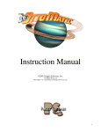
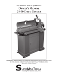
SINGLE PHASE MOTORS
INSTALLATION AND MAINTENANCE MANUAL
March 21, 2006
Irvine, California (800) 474-0520
Indianapolis, Indiana (800) 866-7973
Hamilton, Ontario (800) 809-0330
e-mail: [email protected]
www.sterlingelectric.com
16752 Armstrong Avenue, Irvine, CA 92606
7973 Allison Avenue, Indianapolis, IN 46268
799 Rennie St., Hamilton, Ontario L8H7L4
Website: www.sterlingelectric.com
(800) 474-0520 FAX (949) 474-0543
(800) 866-7973 FAX (800) 474-0543
(800) 809-0330 FAX (905) 547-2381
email:[email protected]
INSTRUCTION MANUAL
CAPACITOR START SINGLE PHASE MOTORS
DANGER
ONLY QUALIFIED ELECTRICAL PERSONNEL FAMILIAR WITH THE CONSTRUCTION AND OPERATION OF THE
EQUIPMENT AND THE HAZARDS INVOLVED SHOULD INSTALL, ADJUST, OPERATE, AND/OR SERVICE THIS
EQUIPMENT. READ AND UNDERSTAND THIS MANUAL IN ITS ENTIRETY BEFORE PROCEEDING. FAILURE TO
OBSERVE THIS CAUTION RESULT IN SEVERE BODILY INJURY OR LOSS OF LIFE.
Read ALL instructions prior to operating motor
Buyer shall be solely responsible for determining the adequacy of the product for any and all
uses to which buyer shall apply the product. The application by buyer shall not be subject to
any implied warranty of fitness for a particular purpose. Information contained in this manual is
considered correct at the time of publication and is subject to change without notice.
SAFETY ALERT
WARNING:
Make certain that the power supply is disconnected before attempting to service
or remove any components. Lock out the power supply and tag it to prevent
unexpected application of power.
CAUTION:
The system of connected rotating parts must be free from critical speed, torsional
or other type vibration, no matter how induced. The responsibility for this system
analysis lies with the purchaser.
CAUTION:
Test run unit to verify operation. If the unit tested is a prototype, that unit must be
of current production.
(1)
(2)
(3)
RECEIVING
Check nameplate data.
Check whether any damage has occurred during transportation. If there is evidence of
rough handling or potential damage in shipment, file a claim immediately with the
carrier. Notify your Sterling Electric sales representative.
Turn motor shaft by hand to check that it turns freely.
LOCATION
(1)
Totally enclosed motors may be installed where dirt, moisture and corrosion are present,
or in outdoor locations. Specially designed washdown duty motors can be used in
sanitary environments were exposure to high pressure wash down procedures are
present.
WARNING:
Installation instructions regarding the use of washdown duty motors and the
location and installation of condensation drain plugs as supplied with the motor
must be followed or the warranty will be void. Consult factory for further
information.
2
MOUNTING
(1)
(2)
(3)
(4)
Mount motor securely on a firm, flat base. All ball bearing motors, horizontal or vertical,
normal thrust, grease lubricated, may be mounted in any position.
Align motor accurately, using a flexible coupling if possible. For drive recommendations,
consult with drive or equipment manufacturer, or Sterling Electric.
V-Belt Sheave Pitch Diameters should not be less than the NEMA recommended values.
Refer to NEMA MG1-14.41.
Tighten belts only enough to prevent belt slippage. Belt speed should not exceed 5000
feet per minute.
POWER SUPPLY AND CONNECTIONS
(1)
(2)
(3)
Nameplate voltage and frequency should agree with power supply. Motor will operate
satisfactorily on line voltage within 10% of nameplate value; or frequency within 5%;
combined variation not to exceed 10%. 230 volt motors can be used on 208 volt
network systems, but with slightly modified performance characteristics.
Dual voltage motors can be connected for the desired voltage by following the
connection diagram on the nameplate.
Wiring of motor and motor control, overload protection and grounding should be in
accordance with the National Electric Code and/or local building codes. Consult wiring
diagrams below. Motors with 6 leads do not contain auto-reset thermal protection.
Motors with 7 leads contain auto-reset thermal protection.
START UP
(1)
(2)
(3)
(4)
Dry the motor windings if motor has been stored in a damp location. In drying, DO NOT
exceed 194 degrees F (90 degrees C).
Disconnect load and start motor. Check direction of rotation. Consult connection
diagram on motor nameplate to change direction of rotation on bi-directional motors.
Connect motor to load. The motor should start up quickly and run smoothly. If not, shut
power off at once. Recheck the assembly including all connections before restarting.
Operate under load for at least one hour. Observe whether any unusual noise or
heating has developed and check operating current against nameplate data.
If excessive vibration is noted, check for loose mounting bolts, too flexible motor support
structure, or transmitted vibration from adjacent machinery. Recheck the coupling
alignment between the motor and the driven equipment.
NOTE: Sterling Electric single phase capacitor start motors utilize a mechanical centrifugal
switching mechanism to engage and disengage the start winding. This switching
mechanism may be heard engaging when the motor is shut off and the shaft is
spinning down. This is considered normal operation.
3
(1)
(2)
MAINTENANCE
INSPECTION: Inspect motor at regular intervals. Keep motor clean and ventilating
openings clear of any obstructions.
LUBRICATION: Pre-lubricated double sealed bearings and shielded bearings are
lubricated for life and do not need to be re-lubricated. The bearings may be changed if
necessary. Bearing sizes are noted on the nameplate. See table for standard bearing
sizes for 56C and 140T motors.
Frame
Size
56C / 140TC
Standard Duty
DE
ODE
6205ZZ
6204ZZ
Washdown Duty
DE
ODE
6205LL
6204LL
RENEWAL PARTS
(1)
(2)
Use only genuine Sterling replacement parts.
When ordering, include model number, serial number, item number and description
(from parts list), and quantity required.
Parts List
Item
No.
1
2
3
4
5
6
7
8
9
10
Description
ODE Ball Bearing
Centrifugal Mechanism
Shaft / Rotor Assembly
Bearing Cap
DE Ball Bearing
Capacitor Cover
Start Capacitor
Stationary Switch
ODE Bracket
Fan Cover*
Qty Item
No.
1
11
1
12
1
13
1
14
1
15
1
16
1
17
1
18
1
19
1
* TEFC Models Only
4
Description
Qty
External Snap Ring*
Outside Fan*
Thru-Bolt
Wave Washer
Terminal Box Assembly
Lead Seal
Frame / Stator Assembly
DE Bracket
Slinger
1
1
1
1
1
1
1
1
1
IMPORTANT INFORMATION
In the event of the resale of any of the goods, in whatever form, Resellers/Buyers will include
the following language in a conspicuous place and in a conspicuous manner in a written
agreement covering such sale:
The manufacturer makes no warranty or representations, expressed or implied,
by operation of law or otherwise, as to the merchantability or fitness for a
particular purpose of the good sold hereunder. Buyer acknowledges that it alone
has determined that the goods purchased hereunder will suitably meet the
requirements of their intended use. In no event will manufacturer be liable for
consequential, incidental or other damages.
Resellers/Buyers agree to also include this entire document including the warnings above in a
conspicuous place and in a conspicuous manner in writing to instruct users on the safe usage of
the product.
This instruction manual should be read together with all other printed information such as
catalogs, supplied by Sterling Electric.
TROUBLESHOOTING
TROUBLE SHOOTER’S GUIDE BASED ON SYMPTOMS
SYMPTOMS
CAUSE
1. Motor does
not start.
2. Motor starts, but
does not come
up to speed.
a. Burnout
b. Incorrect power supply.
b. Burnout
c. Fuse out, loose or open
connection.
d. Open control circuit.
c. Burnout
e. Rotating parts of motor
may be jammed
mechanically.
e. Burnout
f. Driven machine may be
jammed.
g. No power supply.
f. Burnout
h. Faulty Capacitor
h. Burnout
d. None
g. None
REMEDY
a. Connect correctly per
diagram on motor.
b. Use only with correct rated
power supply.
c. Correct open circuit
condition.
d. Correct open circuit
condition.
e. Check and correct:
1. Bent shaft
2. Broken housing
3. Damaged bearing
4. Jammed or broken fan
5. Foreign material in motor
f. Correct jammed condition.
g. Check voltage at motor and
work back to power supply.
h. Replace capacitor
a. Same as 1-a, b, c above.
b. Overload
3. Motor noisy
electrically
RESULT
a. Incorrectly connected.
b. Burnout
a. Same as 1-a, b, c above.
5
b. Reduce load to bring
current to rated limit. Use
proper fuses and overload
protection.
SYMPTOMS
4. Motor runs hot.
Exceeds rating.
5. Motor noisy
mechanically
CAUSE
RESULT
b. Overload
b. Burnout
b. Reduce load.
c. Impaired ventilation.
c. Burnout
c. Remove obstruction.
d. Frequent start or stop.
d. Burnout
e. Imbalance in voltage or
frequency of power supply.
a. Misalignment of coupling
or sprocket.
e. Burnout
d. 1. Reduce number of starts
or reversals.
2. Secure proper motor for
this duty.
e. Check and correct power
supply.
a. Correct misalignment.
b. Mechanical unbalance of
rotating parts.
c. Lack of or improper
lubricant.
d. Foreign material in
lubricant.
e. Overload
6. Bearing
failure
a. Bearing failure, broken
shaft, burnout due to
rotor drag.
b. Same as 5-a
c. Bearing failure
d. Same as 5-c
e. Same as 5-c
f. Shock load.
f. Same as 5-c
g. Mounting acts as amplifier
of normal noise.
h. Rotor dragging due to worn
bearings, shaft or bracket
a. Same as 5-a, b, c, d, e
above.
b. Entry of water or foreign
material into bearing
housing.
g. Annoying
h. Burnout
a. Burnout, damaged
shaft or housing
b. Same as 6-a
above
TYPICAL BURNOUT PATTERNS
SYMPTOM
CAUSED BY
1. Shorted coil
a. Moisture, chemicals, foreign
material in motor, damage
winding.
b. Faulty stationary switch
2. 100% Burnout
3. Other
REMEDY
a. Same as 1-a, b, c above.
a.
b.
c.
d.
e.
a.
b. Find unbalanced part, then
rebalance.
c. Use correct lubricant, and
replace parts as necessary.
d. Clean out or replace
bearing.
e. Remove overload condition.
Replace damaged parts.
f. Correct causes and replace
damaged parts.
g. Isolate motor from base.
h. Replace bearings, shaft or
bracket as needed.
a. Replace bearings and follow
5-a, b, c, d, e above.
b. Replace bearings and shield
against entry of foreign
material (water, dust, etc.)
Use proper motor.
APPEARANCE
a. Black or burned coil with remainder
of winding good.
b. Black or burned coil with remainder of
winding good. Burned contacts on
stationary switch
a. Burned equally all around winding.
b. Burned equally all around winding.
c. Burned equally all around winding.
d. Burned equally all around winding.
e. Burned equally all around winding.
a. Irregular burned groups or spot
burns.
b. Badly damaged burn spot.
Overload.
Stalled.
Impaired ventilation.
Frequent reversal or starting.
Incorrect power.
Improper connection.
b. Ground
WARRANTY (LIMITED)
The warranty will cover all of the parts in the motor for 24 months from the date of shipment.
The warranty is only for parts and labor. In no event shall our liability exceed the original price of the
unit, nor does it cover cost of on site repair, installation, or freight.
Contact the service department for a complete explanation as to the full warranty policies and
conditions of sale.
All dimensions designs and specifications are subject to change without notice.
The information in this user’s manual is subject to change without notice.
6