Download AlphaEclipse 2500/2600 Sign Installation Manual - Alpha
Transcript
October 8, 2003
AlphaEclipse 2500/2600 Series Sign Installation Manual (pn 9711-7001G)
AlphaEclipse 2500/2600 Sign Installation Manual
http://www.adaptivedisplays.com/support/eclipse
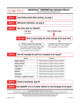
Read Safety section before starting, see page 4
Mechanical installation, see page 6
How many signs are installed?
TWO OR MORE SIGNS
ONE SIGN
• Go to STEP 4.
Must all signs display the same message at the same time?
YES
NO
All signs must be the same size.
• If two signs are mounted back-to-back, follow
directions on page 12. Then go to STEP 4.
• If two signs are mounted back-to-back, follow
directions on page 10. Then go to STEP 4.
• If not, see page 16. Then go to STEP 4.
• If not, see page 14. Then go to STEP 4.
How will messages be sent from a computer to the sign(s)?
Method
Directions
WIRED (RS232)
• Follow directions on page 18. Then go to STEP 5.
WIRED (RS485)
• Follow directions on page 19. Then go to STEP 5.
FIBER OPTIC
• Follow directions on page 20. Then go to STEP 5.
ETHERNET
• Follow directions on page 21. Then go to STEP 5.
MODEM
• Follow directions on page 22. Then go to STEP 5.
WIRELESS
• Follow directions on page 23. Then go to STEP 5.
EXTERNAL CONNECTION BOX
• Follow directions on page 24. Then go to STEP 5.
Electrical installation, page 25
Use AlphaNET v2.0.3 or greater software to send messages to the sign(s)
© Copyright 2003 Adaptive Micro Systems, LLC. All rights reserved.
Adaptive Micro Systems • 7840 North 86th Street • Milwaukee, WI 53224 USA • 414-357-2020 • 414-357-2029 (fax) • http://www.adaptivedisplays.com
Trademarked names appear throughout this document. Rather than list the names and entities that own the trademarks or insert a trademark symbol with each mention of the trademarked name, the publisher states
that it is using names for editorial purposes and to the benefit of the trademark owner with no intention of improperly using the trademark.
The following are trademarks of Adaptive Micro Systems: ActiveX, Adaptive, Alpha, AlphaLert, AlphaNET, AlphaNet plus, AlphaEclipse, AlphaPremiere, AlphaTicker, AlphaVision, AlphaVision InfoTracker, Automode,
BetaBrite, BetaBrite Director, BetaBrite Messaging Software, Big Dot, Director, EZ KEY II, EZ95, PagerNET, PPD, PrintPak, Serial Clock, Smart Alec, Solar, TimeNet.
The distinctive trade dress of this product is a trademark claimed by Adaptive Micro Systems, LLC.
Due to continuing product innovation, specifications in this manual are subject to change without notice.
October 8, 2003
1
9711-7001G
AlphaEclipse 2500/2600 Series Sign Installation Manual (pn 9711-7001G)
October 8, 2003
Contents
Safety. . . . . . . . . . . . . . . . . . . . . . . . . . . . . . . . . . . . . . . . . . . . . . . . . . . . . . . . . . . . . . . . . . . . . . . . . . . 4
Mechanical installation. . . . . . . . . . . . . . . . . . . . . . . . . . . . . . . . . . . . . . . . . . . . . . . . . . . . . . . . . . . . . . 6
Sign-to-sign connections
Back-to-back Master/Slave sign connection . . . . . . . . . . . . . . . . . . . . . . . . . . . . . . . . . . . . . . . . . . . . . . . . . . . . . . . . .10
Back-to-back Master/Master sign connection . . . . . . . . . . . . . . . . . . . . . . . . . . . . . . . . . . . . . . . . . . . . . . . . . . . . . . . .12
Multiple Master/Slave sign connection . . . . . . . . . . . . . . . . . . . . . . . . . . . . . . . . . . . . . . . . . . . . . . . . . . . . . . . . . . . . .14
Multiple Master/Master signs . . . . . . . . . . . . . . . . . . . . . . . . . . . . . . . . . . . . . . . . . . . . . . . . . . . . . . . . . . . . . . . . . . . .16
Computer-to-sign connections
Wired (RS232) computer-to-sign connection . . . . . . . . . . . . . . . . . . . . . . . . . . . . . . . . . . . . . . . . . . . . . . . . . . . . . . . .18
Wired (RS485) computer-to-sign connection . . . . . . . . . . . . . . . . . . . . . . . . . . . . . . . . . . . . . . . . . . . . . . . . . . . . . . . .19
Fiber optic computer-to-sign connection . . . . . . . . . . . . . . . . . . . . . . . . . . . . . . . . . . . . . . . . . . . . . . . . . . . . . . . . . . . .20
Ethernet computer-to-sign connection . . . . . . . . . . . . . . . . . . . . . . . . . . . . . . . . . . . . . . . . . . . . . . . . . . . . . . . . . . . . .21
Modem computer-to-sign connection . . . . . . . . . . . . . . . . . . . . . . . . . . . . . . . . . . . . . . . . . . . . . . . . . . . . . . . . . . . . . .22
Wireless computer-to-sign connection . . . . . . . . . . . . . . . . . . . . . . . . . . . . . . . . . . . . . . . . . . . . . . . . . . . . . . . . . . . . .23
External connection box computer-to-sign connection . . . . . . . . . . . . . . . . . . . . . . . . . . . . . . . . . . . . . . . . . . . . . . . . .24
Electrical installation . . . . . . . . . . . . . . . . . . . . . . . . . . . . . . . . . . . . . . . . . . . . . . . . . . . . . . . . . . . . . . 25
Appendix . . . . . . . . . . . . . . . . . . . . . . . . . . . . . . . . . . . . . . . . . . . . . . . . . . . . . . . . . . . . . . . . . . . . . . . 27
Appendix A: Sign description . . . . . . . . . . . . . . . . . . . . . . . . . . . . . . . . . . . . . . . . . . . . . . . . . . . . . . . . . . . . . . . . . . . . .27
Outside view . . . . . . . . . . . . . . . . . . . . . . . . . . . . . . . . . . . . . . . . . . . . . . . . . . . . . . . . . . . . . . . . . . . . . . . . . . . . .27
Inside view . . . . . . . . . . . . . . . . . . . . . . . . . . . . . . . . . . . . . . . . . . . . . . . . . . . . . . . . . . . . . . . . . . . . . . . . . . . . . .28
Appendix B: Equipment identification . . . . . . . . . . . . . . . . . . . . . . . . . . . . . . . . . . . . . . . . . . . . . . . . . . . . . . . . . . . . . .30
Appendix C: Networking signs . . . . . . . . . . . . . . . . . . . . . . . . . . . . . . . . . . . . . . . . . . . . . . . . . . . . . . . . . . . . . . . . . . . .31
Computer-to-sign communication methods . . . . . . . . . . . . . . . . . . . . . . . . . . . . . . . . . . . . . . . . . . . . . . . . . . . . .31
Sign-to-sign communication methods . . . . . . . . . . . . . . . . . . . . . . . . . . . . . . . . . . . . . . . . . . . . . . . . . . . . . . . . .32
Sign network design . . . . . . . . . . . . . . . . . . . . . . . . . . . . . . . . . . . . . . . . . . . . . . . . . . . . . . . . . . . . . . . . . . . . . . .33
Appendix D: Opening and closing the sign. . . . . . . . . . . . . . . . . . . . . . . . . . . . . . . . . . . . . . . . . . . . . . . . . . . . . . . . . . .34
Appendix E: Sign options . . . . . . . . . . . . . . . . . . . . . . . . . . . . . . . . . . . . . . . . . . . . . . . . . . . . . . . . . . . . . . . . . . . . . . . .37
Temperature probe option. . . . . . . . . . . . . . . . . . . . . . . . . . . . . . . . . . . . . . . . . . . . . . . . . . . . . . . . . . . . . . . . . . .37
Modem option. . . . . . . . . . . . . . . . . . . . . . . . . . . . . . . . . . . . . . . . . . . . . . . . . . . . . . . . . . . . . . . . . . . . . . . . . . . .38
Wireless transceiver option . . . . . . . . . . . . . . . . . . . . . . . . . . . . . . . . . . . . . . . . . . . . . . . . . . . . . . . . . . . . . . . . . .39
Fiber optic modem option . . . . . . . . . . . . . . . . . . . . . . . . . . . . . . . . . . . . . . . . . . . . . . . . . . . . . . . . . . . . . . . . . . .41
Appendix F: Termination . . . . . . . . . . . . . . . . . . . . . . . . . . . . . . . . . . . . . . . . . . . . . . . . . . . . . . . . . . . . . . . . . . . . . . . .43
Location of termination DIP switches . . . . . . . . . . . . . . . . . . . . . . . . . . . . . . . . . . . . . . . . . . . . . . . . . . . . . . . . . .43
How to set the termination DIP switches. . . . . . . . . . . . . . . . . . . . . . . . . . . . . . . . . . . . . . . . . . . . . . . . . . . . . . . .43
Appendix G: DIP switch settings . . . . . . . . . . . . . . . . . . . . . . . . . . . . . . . . . . . . . . . . . . . . . . . . . . . . . . . . . . . . . . . . . .45
2
Contents
October 8, 2003
AlphaEclipse 2500/2600 Series Sign Installation Manual (pn 9711-7001G)
DIP switch locations . . . . . . . . . . . . . . . . . . . . . . . . . . . . . . . . . . . . . . . . . . . . . . . . . . . . . . . . . . . . . . . . . . . . . . .45
Sign operation settings (Bank 1 and Bank 2 DIP switches). . . . . . . . . . . . . . . . . . . . . . . . . . . . . . . . . . . . . . . . . .46
Sign size settings (Bank 3 DIP switches) . . . . . . . . . . . . . . . . . . . . . . . . . . . . . . . . . . . . . . . . . . . . . . . . . . . . . . .47
Using AlphaNET software to set DIP switches. . . . . . . . . . . . . . . . . . . . . . . . . . . . . . . . . . . . . . . . . . . . . . . . . . . .48
Appendix H: Sign Specifications . . . . . . . . . . . . . . . . . . . . . . . . . . . . . . . . . . . . . . . . . . . . . . . . . . . . . . . . . . . . . . . . . .49
EMI compliance. . . . . . . . . . . . . . . . . . . . . . . . . . . . . . . . . . . . . . . . . . . . . . . . . . . . . . . . . . . . . . . . . . . . . . . . . . .49
Temperature protection. . . . . . . . . . . . . . . . . . . . . . . . . . . . . . . . . . . . . . . . . . . . . . . . . . . . . . . . . . . . . . . . . . . . .49
Technical specifications . . . . . . . . . . . . . . . . . . . . . . . . . . . . . . . . . . . . . . . . . . . . . . . . . . . . . . . . . . . . . . . . . . . .50
Appendix I: Using an IR Message Loader or a computer with an external connection box . . . . . . . . . . . . . . . . . . . . . .52
IR Message Loader with an external connection box . . . . . . . . . . . . . . . . . . . . . . . . . . . . . . . . . . . . . . . . . . . . . .52
Computer with an external connection box . . . . . . . . . . . . . . . . . . . . . . . . . . . . . . . . . . . . . . . . . . . . . . . . . . . . . .52
Appendix J: Controller board . . . . . . . . . . . . . . . . . . . . . . . . . . . . . . . . . . . . . . . . . . . . . . . . . . . . . . . . . . . . . . . . . . . . .53
Contents
3
AlphaEclipse 2500/2600 Series Sign Installation Manual (pn 9711-7001G)
October 8, 2003
Safety
Equipment symbols
Chassis ground
Mains power (I = ON, 0 = OFF)
Warnings and cautions
WARNING
Hazardous voltage.
Contact with high voltage
may cause death or serious
injury.
Always disconnect power to
unit prior to servicing. SM1000A
Other warnings and cautions are posted in appropriate locations throughout this manual.
Battery backup
In the event of a power loss, backup batteries in an AlphaEclipse sign provide short-term power in order to
retain information such as messages and time settings.
Backup batteries are soldered to the Controller board and should not be replaced by anyone other than a
qualified Adaptive technician.
WARNING
Danger of explosion if battery is
incorrectly replaced. Replace only
with the same or equivalent type
recommended by the manufacturer.
Dispose of used batteries according
to the manufacturer's instructions.
SM1019A-En
AVERTISSEMENT
WARNUNG
SM1019A-Fr
AVVERTENZA
ADVERTENCIA
SM1019A-It
4
SM1019A-Ge
SM1019A-Sp
Safety
October 8, 2003
AlphaEclipse 2500/2600 Series Sign Installation Manual (pn 9711-7001G)
Preventing Electrostatic Discharge (ESD) Damage
ATTENTION
OBSERVE PRECAUTIONS
ELECTROSTATIC
SENSITIVE DEVICE
This equipment contains components that may be damaged by “static electricity”, or electrostatic discharge.
To prevent this from happening, be sure to follow the guidelines in Adaptive Tech Memo 00-0005, “Preventing
Electrostatic Discharge (ESD) Damage,” available on our Web site at http://www.adaptivedisplays.com.
Changing from Master/Slave to Master/Master operation
Master/Slave sign operation (see page 10 and page 14) — in this mode, a message will be displayed on all the
signs at the same time. Also, in this mode, there is just one Master sign, but there can be multiple Slave signs.
Messages are sent to the Master sign using a wire, modem, or wireless connection. Then these messages are sent
and displayed on all the Slave signs (plus the Master sign) at the same time.
Master/Master sign operation (see page 12 and page 16) — in this mode, each sign can display a different
message. However, a message cannot be displayed simultaneously on all the signs.
Signs are configured for Master/Slave mode by:
1.
wiring a RS485 connection to each sign’s SERIAL I/O connector (also called the Serial I/O terminal block,
see “Appendix A: Sign description” on page 27),
2.
wiring a RS485 connection to each sign’s TEMP/SYNC PORT connector,
3.
setting each sign’s Master/Slave DIP switch, depending if the sign is operating as a Master or a Slave. The
DIP switches on a sign can be set by either:
•
opening a sign and then physically setting the DIP switches (see “Appendix G: DIP switch settings” on
page 45)
•
using AlphaNET v2.0.3 or greater Diagnostics software (see the AlphaNET User Manual available on
Adaptive’s Web site).
Signs set up as Master/Slave units as described above can not be changed to Master/Master operation by
just changing a sign’s DIP switches (#3 above). In fact, doing so could damage a sign.
To change Master/Slave signs to Master/Master units, use the directions below:
•
“Back-to-back Master/Master sign connection” on page 12 or
•
“Multiple Master/Master signs” on page 16.
Safety
5
AlphaEclipse 2500/2600 Series Sign Installation Manual (pn 9711-7001G)
October 8, 2003
Mechanical installation
Designing the support structure
WARNING
Possible crush hazard.
Mounting system must be
able to safely support the
unit's weight. Otherwise
the unit may fall, causing
serious injury or death.
SM1014
The design of the support structure depends on the mounting methods, sign size, sign weight, and wind
loading. Support structure design should only be done by a qualified individual.
It is the customer’s responsibility to ensure that the support structure and sign mounting hardware are capable
of supporting the sign and are in compliance with all applicable building codes.
Adaptive Micro Systems is not responsible for installations or the structural integrity of support structures done by
others.
Lifting the sign
WARNING
WARNING
Possible crush hazard.
Always use lifting bar
to lift the sign. Otherwise
eyebolts may break and
sign may fall, causing
serious injury or death.
Possible crush hazard.
Always use eyebolts to lift
sign. Otherwise the sign
may fall, causing serious
injury or death.
SM1017
SM1015
Use the two eyebolts on the sign with a lifting bar to raise the display:
Lifting bar
RIGHT WAY
TO LIFT SIGN
6
The eyebolts may
shear off if the sign
is lifted this way.
WRONG WAY
TO LIFT SIGN
Mechanical installation
October 8, 2003
AlphaEclipse 2500/2600 Series Sign Installation Manual (pn 9711-7001G)
Mounting the sign
Because every installation site is unique, there is no single, Adaptive-approved procedure for mounting an
AlphaEclipse sign.
However, follow these guidelines when installing a sign:
•
Consult with a professional sign installer to determine the proper mounting system and to comply with all
applicable building codes.
•
Only use the sign’s mounting support brackets to mount the sign. Mounting to any other parts of the sign will
void the warranty.
•
All top and bottom mounting support brackets should be used to mount the sign.
•
Drill holes as needed in the sign’s mounting support brackets for fasteners. Drilling holes in any other place
on the sign will void the warranty. Follow these guidelines when drilling holes in the mounting support
brackets:
–
–
–
Drill the minimum number of holes necessary.
The distance from the center line of a mounting bolt to the outside edge of a mounting support bracket
should not be less than two times the diameter of the fasteners.
To prevent bi-metal corrosion, dissimilar material should be isolated when mounting the sign.
•
If the sign is mounted to a solid surface like a wall, nothing should block the space between the top,
bottom, and sides of the sign and the solid surface. If there is an obstruction (as in a monument-style
installation), then run ductwork (not supplied) from the bottom of each fan cover to the side edge of the
sign. Do not run ductwork to the top of the sign as rain or other material could enter the sign. Do not run
the ductwork to the bottom of the sign as this could force exhaust air back into the sign.
•
Allow fan clearance as shown below:
Lifting bolt
Only use eyebolt for lifting, not for mounting sign.
Mounting support bracket (upper)
Fan cover
The mounting support brackets
and eyebolts are steel.
For adequate air circulation, allow at least 3
inches of clearance below the fan covers and
the fresh air intakes at bottom of the sign.
Adaptive recommends isolating the fresh air
intakes from the exhaust fans.
The sign case is aluminum.
Exhaust air
For monument-type installations where the
sign is enclosed, the fan covers and fresh air
intakes should be ducted so that exhaust air
is not recirculated into the fresh air intakes.
If this is not done, the sign could overheat
and shut down.
Stainless steel bolts are used to
attach the mounting support
brackets to the sign.
Mounting support bracket (lower)
Fresh air intakes
Figure 1: Mounting an AlphaEclipse 2500/2600 sign
Mounting a temperature probe
See “Appendix E: Sign options” on page 37.
Mechanical installation
7
8
4.0
4.0
"D"
DISPLAY
HEIGHT
4.0
3.0
31.0
2.0
4.0 TYP.
4.0
"C"
DISPLAY WIDTH
"A"
CASE WIDTH
2.88
"B"
CASE
HEIGHT
1.25 MIN
.15
5.18
8.05
3.00
LED Pitch
(2 digit code)
25 = 0.45"
26 = 0.60"
LED Lamp Type
(2 digit code)
00 = 30 degree lamp
01 = 70 degree lamp
Width (Pixel Columns)
x Height (Pixel Rows)
Red lamp/Amber lamp
Model Number Explanation
2_ _ _- 192 x 64 R/A
AlphaEclipse
AlphaEclipse
AlphaEclipse
AlphaEclipse
AlphaEclipse
AlphaEclipse
AlphaEclipse
AlphaEclipse
AlphaEclipse
AlphaEclipse
AlphaEclipse
AlphaEclipse
AlphaEclipse
AlphaEclipse
AlphaEclipse
AlphaEclipse
AlphaEclipse
AlphaEclipse
AlphaEclipse
AlphaEclipse
26_
26_
26_
26_
26_
26_
26_
26_
26_
26_
26_
26_
26_
26_
26_
26_
26_
26_
26_
26_
85
120
145
175
135
160
185
215
155
180
205
235
215
240
265
295
255
280
305
345
"E"
COVER OPEN
_-96x16 R/A
_-128x16 R/A
_-160x16 R/A
_-192x16 R/A
_-96x32 R/A
_-128x32 R/A
_-160x32 R/A
_-192x32 R/A
_-96x48 R/A
_-128x48 R/A
_-160x48 R/A
_-192x48 R/A
_-96x64 R/A
_-128x64 R/A
_-160x64 R/A
_-192x64 R/A
_-96x80 R/A
_-128x80 R/A
_-160x80 R/A
_-192x80 R/A
15.07
15.07
15.07
15.07
24.67
24.67
24.67
24.67
34.27
34.27
34.27
34.27
43.87
43.87
43.87
43.87
53.47
53.47
53.47
53.47
DIM "B"
12.67
12.67
12.67
12.67
19.87
19.87
19.87
19.87
27.07
27.07
27.07
27.07
34.27
34.27
34.27
34.27
41.47
41.47
41.47
41.47
See Figure 3 on page 9
for a larger version of
this table.
63.13
82.33
101.53
120.73
63.13
82.33
101.53
120.73
63.13
82.33
101.53
120.73
63.13
82.33
101.53
120.73
63.13
82.33
101.53
120.73
ASSEMBLY MODEL NO
WEIGHT (lbs) DIM "A"
AlphaEclipse 25_ _-96x16 R/A
60
48.73
AlphaEclipse 25_ _-128x16 R/A
85
63.13
AlphaEclipse 25_ _-160x16 R/A
105
77.53
AlphaEclipse 25_ _-192x16 R/A
125
91.93
AlphaEclipse 25_ _-96x32 R/A
95
48.73
AlphaEclipse 25_ _-128x32 R/A
115
63.13
AlphaEclipse 25_ _-160x32 R/A
135
77.53
AlphaEclipse 25_ _-192x32 R/A
155
91.93
AlphaEclipse 25_ _-96x48 R/A
110
48.73
AlphaEclipse 25_ _-128x48 R/A
130
63.13
AlphaEclipse 25_ _-160x48 R/A
150
77.53
AlphaEclipse 25_ _-192x48 R/A
170
91.93
AlphaEclipse 25_ _-96x64 R/A
48.73
155
AlphaEclipse 25_ _-128x64 R/A
175
63.13
AlphaEclipse 25_ _-160x64 R/A
77.53
195
AlphaEclipse 25_ _-192x64 R/A
91.93
215
AlphaEclipse 25_ _-96x80 R/A
185
48.73
AlphaEclipse 25_ _-128x80 R/A
205
63.13
AlphaEclipse 25_ _-160x80 R/A
225
77.53
AlphaEclipse 25_ _-192x80 R/A
255
91.93
57.60
76.80
96.00
115.20
57.60
76.80
96.00
115.20
57.60
76.80
96.00
115.20
57.60
76.80
96.00
115.20
57.60
76.80
96.00
115.20
DIM "C"
43.20
57.60
72.00
86.40
43.20
57.60
72.00
86.40
43.20
57.60
72.00
86.40
43.20
57.60
72.00
86.40
43.20
57.60
72.00
86.40
9.60
9.60
9.60
9.60
19.20
19.20
19.20
19.20
28.80
28.80
28.80
28.80
38.40
38.40
38.40
38.00
48.00
48.00
48.00
48.00
DIM "D"
7.20
7.20
7.20
7.20
14.40
14.40
14.40
14.40
21.60
21.60
21.60
21.60
28.80
28.80
28.80
28.80
36.00
36.00
36.00
36.00
21.0
21.0
21.0
21.0
30.6
30.6
30.6
30.6
40.2
40.2
40.2
40.2
49.8
49.8
49.8
49.8
59.4
59.4
59.4
59.4
DIM "E"
18.6
18.6
18.6
18.6
25.8
25.8
25.8
25.8
33.0
33.0
33.0
33.0
40.2
40.2
40.2
40.2
47.4
47.4
47.4
47.4
AlphaEclipse 2500/2600 Series Sign Installation Manual (pn 9711-7001G)
October 8, 2003
Installation diagram
Figure 2: AlphaEclipse installation diagram - Part 1
Mechanical installation
2_ _ _- 192 x 64 R/A
Mechanical installation
LED Pitch
(2 digit code)
25 = 0.45"
26 = 0.60"
LED Lamp Type
(2 digit code)
00 = 30 degree lamp
01 = 70 degree lamp
Width (Pixel Columns)
x Height (Pixel Rows)
Red lamp/Amber lamp
Model Number Explanation
85
120
145
175
135
160
185
215
155
180
205
235
215
240
265
295
255
280
305
345
15.07
15.07
15.07
15.07
24.67
24.67
24.67
24.67
34.27
34.27
34.27
34.27
43.87
43.87
43.87
43.87
53.47
53.47
53.47
53.47
57.60
76.80
96.00
115.20
57.60
76.80
96.00
115.20
57.60
76.80
96.00
115.20
57.60
76.80
96.00
115.20
57.60
76.80
96.00
115.20
9.60
9.60
9.60
9.60
19.20
19.20
19.20
19.20
28.80
28.80
28.80
28.80
38.40
38.40
38.40
38.00
48.00
48.00
48.00
48.00
21.0
21.0
21.0
21.0
30.6
30.6
30.6
30.6
40.2
40.2
40.2
40.2
49.8
49.8
49.8
49.8
59.4
59.4
59.4
59.4
63.13
82.33
101.53
120.73
63.13
82.33
101.53
120.73
63.13
82.33
101.53
120.73
63.13
82.33
101.53
120.73
63.13
82.33
101.53
120.73
_-96x16 R/A
_-128x16 R/A
_-160x16 R/A
_-192x16 R/A
_-96x32 R/A
_-128x32 R/A
_-160x32 R/A
_-192x32 R/A
_-96x48 R/A
_-128x48 R/A
_-160x48 R/A
_-192x48 R/A
_-96x64 R/A
_-128x64 R/A
_-160x64 R/A
_-192x64 R/A
_-96x80 R/A
_-128x80 R/A
_-160x80 R/A
_-192x80 R/A
AlphaEclipse
AlphaEclipse
AlphaEclipse
AlphaEclipse
AlphaEclipse
AlphaEclipse
AlphaEclipse
AlphaEclipse
AlphaEclipse
AlphaEclipse
AlphaEclipse
AlphaEclipse
AlphaEclipse
AlphaEclipse
AlphaEclipse
AlphaEclipse
AlphaEclipse
AlphaEclipse
AlphaEclipse
AlphaEclipse
26_
26_
26_
26_
26_
26_
26_
26_
26_
26_
26_
26_
26_
26_
26_
26_
26_
26_
26_
26_
DIM "A" DIM "B" DIM "C" DIM "D" DIM "E"
43.20
7.20
18.6
48.73
12.67
7.20
18.6
12.67
57.60
63.13
7.20
72.00
18.6
77.53
12.67
7.20
86.40
91.93
18.6
12.67
48.73
14.40
43.20
25.8
19.87
14.40
63.13
57.60
19.87
25.8
14.40
19.87
25.8
77.53
72.00
25.8
14.40
91.93
86.40
19.87
33.0
48.73
21.60
43.20
27.07
21.60
27.07
33.0
63.13
57.60
27.07
33.0
21.60
77.53
72.00
33.0
21.60
27.07
91.93
86.40
40.2
48.73
28.80
43.20
34.27
28.80
40.2
63.13
57.60
34.27
34.27
77.53
28.80
72.00
40.2
91.93
28.80
40.2
34.27
86.40
36.00
41.47
48.73
43.20
47.4
36.00
47.4
41.47
63.13
57.60
36.00
47.4
41.47
77.53
72.00
41.47
36.00
47.4
91.93
86.40
ASSEMBLY MODEL NO
WEIGHT (lbs)
AlphaEclipse 25_ _-96x16 R/A
60
AlphaEclipse 25_ _-128x16 R/A
85
AlphaEclipse 25_ _-160x16 R/A
105
AlphaEclipse 25_ _-192x16 R/A
125
AlphaEclipse 25_ _-96x32 R/A
95
AlphaEclipse 25_ _-128x32 R/A
115
AlphaEclipse 25_ _-160x32 R/A
135
AlphaEclipse 25_ _-192x32 R/A
155
AlphaEclipse 25_ _-96x48 R/A
110
AlphaEclipse 25_ _-128x48 R/A
130
AlphaEclipse 25_ _-160x48 R/A
150
AlphaEclipse 25_ _-192x48 R/A
170
AlphaEclipse 25_ _-96x64 R/A
155
AlphaEclipse 25_ _-128x64 R/A
175
AlphaEclipse 25_ _-160x64 R/A
195
AlphaEclipse 25_ _-192x64 R/A
215
AlphaEclipse 25_ _-96x80 R/A
185
AlphaEclipse 25_ _-128x80 R/A
205
AlphaEclipse 25_ _-160x80 R/A
225
AlphaEclipse 25_ _-192x80 R/A
255
October 8, 2003
AlphaEclipse 2500/2600 Series Sign Installation Manual (pn 9711-7001G)
Figure 3: AlphaEclipse installation diagram - Part 2
9
AlphaEclipse 2500/2600 Series Sign Installation Manual (pn 9711-7001G)
October 8, 2003
Back-to-back Master/Slave sign connection
1.
Open the sign according to “Appendix D: Opening and closing the sign” on page 34.
Connect signal wire
2.
Connect the two signs as shown below:
•
The Master sign will have a modem or wireless transceiver inside, or the Master sign will be connected
to a computer by wire, fiber optic cable, or an external connection box.
•
The Slave sign will only be connected to a Master sign.
•
A one-line sign does not include a Serial I/O terminal block. Connect RS485+, RS485-, and SHIELD
directly to the Serial Port on the controller board. See page 53.
Both signs must be
the same size in a
Master/Slave network.
SERIAL I/O
Master Sign
The Master sign will be connected
to a modem, wireless transceiver,
computer, or external connection box
at this terminal block.
RS485 + (Black)
RS485 - (Red)
SHIELD
TEMP/SYNC PORT
RS485 – (Red)
RS485 + (Black)
SHIELD
DIP switches
(underneath)
Turbo Extender Board
Signal
Conduit
Opening
Controller Board
Conduit
For SERIAL I/O
and TEMP/SYNC
PORT, use
RS485 wire,
22AWG,
rated for
outdoor use
(pn 7122-0284).
SERIAL I/O
Slave Sign
RS485 + (Black)
RS485 - (Red)
SHIELD
TEMP/SYNC PORT
RS485 – (Red)
RS485 + (Black)
SHIELD
DIP switches
(underneath)
Turbo Extender Board
Controller Board
Signal
Conduit
Opening
Figure 4: Back-to-back Master/Slave sign connection
10
Back-to-back Master/Slave sign connection
October 8, 2003
AlphaEclipse 2500/2600 Series Sign Installation Manual (pn 9711-7001G)
Set DIP switches
These are the recommended DIP switch settings for a Master/Slave back-to-back sign connection:
Master sign settings:
Controller board
(side view)
DIP switches
Bank 2
Bank 1
1 2 3 4 5 6 7 8 910
1 2 3 4 5 6 7 8 910
ON
ON
ON
Serial address
Set DIP switch 1 = ON.
Master/Slave
Set DIP switch 7 = OFF.
This sets the Master sign’s address = 1.
This makes this the Master sign.
Termination
For DIP switches 1 & 2, see
“Appendix F: Termination” on
page 43.
Slave sign settings:
Bank 2
Bank 1
1 2 3 4 5 6 7 8 910
1 2 3 4 5 6 7 8 910
ON
ON
ON
Serial address
Set DIP switch 2 = ON.
Master/Slave
Set DIP switch 7 = ON.
This sets the Slave sign’s address = 2.
This makes this a Slave sign.
Termination
For DIP switches 1 & 2, see
“Appendix F: Termination” on
page 43.
NOTE: Signs set up as Master/Slave units can NOT be changed to Master/Master operation by just
changing a sign’s DIP switches. Doing so could damage a sign. Be sure to disconnect the TEMP/
SYNC wiring so that the Master/Master configuration matches the wiring shown in Figure 5 on
page 12.
Back-to-back Master/Slave sign connection
11
AlphaEclipse 2500/2600 Series Sign Installation Manual (pn 9711-7001G)
October 8, 2003
Back-to-back Master/Master sign connection
1.
Open the sign according to “Appendix D: Opening and closing the sign” on page 34.
Connect signal wire
2.
Connect the two signs as shown below:
•
Each Master sign will have a modem or wireless transceiver inside, or one of the Master signs will be
connected to a computer by wire, fiber optic cable, or an external connection box.
•
If both Master signs have a modem or a wireless transceiver inside or each sign is connected to an
external connection box, then the wire connecting both signs shown below is not necessary.
•
A one-line sign does not include a Serial I/O terminal block. Connect RS485+, RS485-, and SHIELD
directly to the Serial Port on the controller board. See page 53.
SERIAL I/O
First Master Sign
RS485 + (Black)
RS485 - (Red)
One of the Master signs will be connected
to a modem, wireless transceiver,
computer, or external connection box
at this terminal block.
SHIELD
DIP switches
(underneath)
Turbo Extender Board
Signal
Conduit
Opening
Controller Board
Conduit
SERIAL I/O
Second Master Sign
RS485 + (Black)
RS485 - (Red)
Use RS485
wire, 22AWG,
rated for
outdoor use
(pn 7122-0284).
SHIELD
DIP switches
(underneath)
Turbo Extender Board
Controller Board
Signal
Conduit
Opening
Figure 5: Back-to-back Master/Master sign connection
12
Back-to-back Master/Master sign connection
October 8, 2003
AlphaEclipse 2500/2600 Series Sign Installation Manual (pn 9711-7001G)
Set DIP switches
These are the recommended DIP switch settings for a Master/Master back-to-back sign connection:
First Master sign settings:
Controller board
(side view)
DIP switches
Bank 2
Bank 1
1 2 3 4 5 6 7 8 910
ON
1 2 3 4 5 6 7 8 910
ON
ON
Serial address
Set DIP switch 1 = ON.
Master/Slave
Set DIP switch 7 = OFF.
This sets the first Master sign’s address = 1.
This makes this the Master sign.
Termination
For DIP switches 1 & 2, see
“Appendix F: Termination” on
page 43.
This allows you to send messages to just the
first Master sign if you send messages to sign
address 1. (See the AlphaNET User Manual
for more information.)
Second Master sign settings:
Bank 2
Bank 1
1 2 3 4 5 6 7 8 910
ON
1 2 3 4 5 6 7 8 910
ON
ON
Serial address
Set DIP switch 2 = ON.
Master/Slave
Set DIP switch 7 = OFF.
This sets the second Master sign’s address = 2.
This makes this a Master sign.
Termination
For DIP switches 1 & 2, see
“Appendix F: Termination” on
page 43.
This allows you to send messages to just the
second Master sign if you send messages to
sign address 2. (See the AlphaNET User
Manual for more information.)
Back-to-back Master/Master sign connection
13
AlphaEclipse 2500/2600 Series Sign Installation Manual (pn 9711-7001G)
October 8, 2003
Multiple Master/Slave sign connection
1.
Open the sign according to “Appendix D: Opening and closing the sign” on page 34.
Connect signal wire
2.
Connect the signs as shown below:
•
The Master sign will have a modem or wireless transceiver inside, or the Master sign will be connected
to a computer by wire, fiber optic cable, or an external connection box.
•
A one-line sign does not include a Serial I/O terminal block. Connect RS485+, RS485-, and SHIELD
directly to the Serial Port on the controller board. See page 53.
SERIAL I/O
Master Sign
The Master sign will be connected
to a modem, wireless transceiver,
computer, or external connection box
at this terminal block.
RS485 + (Black)
RS485 - (Red)
All signs must be the
same size in a Master/
Slave network.
SHIELD
TEMP/SYNC PORT
RS485 – (Red)
RS485 + (Black)
SHIELD
DIP switches
(underneath)
Turbo Extender Board
Signal
Conduit
Opening
Controller Board
SERIAL I/O
First Slave Sign
Conduit
RS485 + (Black)
RS485 - (Red)
For SERIAL I/O
and TEMP/SYNC
PORT, use
RS485 wire,
22AWG, rated
for outdoor use
(pn 7122-0284).
SHIELD
TEMP/SYNC PORT
RS485 – (Red)
RS485 + (Black)
SHIELD
DIP switches
(underneath)
Turbo Extender Board
Signal
Conduit
Opening
Controller Board
SERIAL I/O
Last Slave Sign
RS485 + (Black)
RS485 - (Red)
SHIELD
TEMP/SYNC PORT
RS485 – (Red)
RS485 + (Black)
SHIELD
DIP switches
(underneath)
Turbo Extender Board
Controller Board
Signal
Conduit
Opening
Figure 6: Multiple Master/Slave sign connection
14
Multiple Master/Slave sign connection
October 8, 2003
AlphaEclipse 2500/2600 Series Sign Installation Manual (pn 9711-7001G)
Set DIP switches
These are the recommended DIP switch settings for Master/Slave multiple sign connection:
Master sign settings:
Controller board
(side view)
DIP switches
Bank 2
Bank 1
1 2 3 4 5 6 7 8 910
1 2 3 4 5 6 7 8 910
ON
ON
ON
Serial address
Set DIP switch 1 = ON.
Master/Slave
Set DIP switch 7 = OFF.
This sets this sign’s address = 1.
This makes this the Master sign.
Termination
For DIP switches 1 & 2, see
“Appendix F: Termination” on
page 43.
First Slave sign settings:
Bank 2
Bank 1
1 2 3 4 5 6 7 8 910
ON
1 2 3 4 5 6 7 8 910
ON
ON
Serial address
Set DIP switch 2 = ON.
Master/Slave
Set DIP switch 7 = ON.
This sets this sign’s address = 2.
This makes this a Slave sign.
Termination
For DIP switches 1 & 2, see
“Appendix F: Termination” on
page 43.
Last Slave sign settings:
Bank 2
Bank 1
1 2 3 4 5 6 7 8 910
ON
1 2 3 4 5 6 7 8 910
ON
ON
Serial address
Set DIP switches 1 & 2 = ON.
This sets this sign’s address = 3.
Master/Slave
Set DIP switch 7 = ON.
This makes this a Slave sign.
Termination
For DIP switches 1 & 2, see
“Appendix F: Termination” on
page 43.
(If this was the 4th sign, then set the
serial address = 4.)
NOTE: Signs set up as Master/Slave units can not be changed to Master/Master operation by just changing
a sign’s DIP switches. Doing so could damage a sign. Be sure to disconnect the TEMP/SYNC wiring
so that the Master/Master configuration matches the wiring shown in Figure 7 on page 16.
Multiple Master/Slave sign connection
15
AlphaEclipse 2500/2600 Series Sign Installation Manual (pn 9711-7001G)
October 8, 2003
Multiple Master/Master signs
1.
Open the sign according to “Appendix D: Opening and closing the sign” on page 34.
Connect signal wire
2.
Connect the signs as shown below:
•
Each Master sign will have a modem or wireless transceiver inside, or one of the Master signs will be
connected to a computer by wire, fiber optic cable, or an external connection box.
•
If all Master signs have a modem or a wireless transceiver inside or each sign is connected to an
external connection box, then the wire connecting the signs shown below is not necessary.
•
A one-line sign does not include a Serial I/O terminal block. Connect RS485+, RS485-, and SHIELD
directly to the Serial Port on the controller board. See page 53.
SERIAL I/O
First Master Sign
RS485 + (Black)
RS485 - (Red)
The Master sign will be connected
to a modem, wireless transceiver,
computer, or external connection box
at this terminal block.
SHIELD
DIP switches
(underneath)
Turbo Extender Board
Signal
Conduit
Opening
Controller Board
SERIAL I/O
Second Master Sign
Conduit
RS485 + (Black)
RS485 - (Red)
For SERIAL I/O,
use RS485 wire,
22AWG, rated
for outdoor use
(pn 7122-0284).
SHIELD
DIP switches
(underneath)
Turbo Extender Board
Signal
Conduit
Opening
Controller Board
SERIAL I/O
Last Master Sign
RS485 + (Black)
RS485 - (Red)
SHIELD
DIP switches
(underneath)
Turbo Extender Board
Controller Board
Signal
Conduit
Opening
Figure 7: Multiple Master/Master sign connection
16
Multiple Master/Master signs
October 8, 2003
AlphaEclipse 2500/2600 Series Sign Installation Manual (pn 9711-7001G)
Set DIP switches
These are the recommended DIP switch settings for Master/Master multiple sign connection:
First Master sign settings:
Controller board
(side view)
DIP switches
Bank 2
Bank 1
1 2 3 4 5 6 7 8 910
1 2 3 4 5 6 7 8 910
ON
ON
ON
Serial address
Set DIP switch 1 = ON.
Master/Slave
Set DIP switch 7 = OFF.
This sets this sign’s address = 1.
This makes this the Master sign.
Termination
For DIP switches 1 & 2, see
“Appendix F: Termination” on
page 43.
Second Master sign settings:
Bank 2
Bank 1
1 2 3 4 5 6 7 8 910
ON
1 2 3 4 5 6 7 8 910
ON
ON
Serial address
Set DIP switch 2 = ON.
Master/Slave
Set DIP switch 7 = OFF.
This sets this sign’s address = 2.
This makes this a Master sign.
Termination
For DIP switches 1 & 2, see
“Appendix F: Termination” on
page 43.
Last Master sign settings:
Bank 2
Bank 1
1 2 3 4 5 6 7 8 910
1 2 3 4 5 6 7 8 910
ON
ON
ON
Serial address
Set DIP switches 1 & 2 = ON.
This sets this sign’s address = 3.
Master/Slave
Set DIP switch 7 = OFF.
This makes this a Master sign.
Termination
For DIP switches 1 & 2, see
“Appendix F: Termination” on
page 43.
(If this was the 4th sign, then set the
serial address = 4.)
Multiple Master/Master signs
17
AlphaEclipse 2500/2600 Series Sign Installation Manual (pn 9711-7001G)
October 8, 2003
Wired (RS232) computer-to-sign connection
1.
Open the sign according to “Appendix D: Opening and closing the sign” on page 34.
2.
Connect the computer to the sign as shown below:
NOTE: A one-line sign does not include a Serial I/O terminal block. Connect RS232 TxD, RS232 RxD, and
GND directly to the Serial Port on the controller board.
up to 50 feet
Overview
Message 1
AlphaEclipse 2500/2600 series sign
Computer running
AlphaNET messaging
software
SERIAL PORT
(on Controller board)
Internal sign
connections
N/C
GND
RS232 RxD
RS232 TxD
SHIELD
RS485 –
RS485 +
GRN
RS232 RXD
ORN
RS232 TXD
BLU
Signal GND
Serial I/O
terminal block
Computer COM
(RS232) port
Figure 8: Wired RS232 computer-to-sign connection
18
Wired (RS232) computer-to-sign connection
October 8, 2003
AlphaEclipse 2500/2600 Series Sign Installation Manual (pn 9711-7001G)
Wired (RS485) computer-to-sign connection
1.
Open the sign according to “Appendix D: Opening and closing the sign” on page 34.
2.
Connect the computer to the sign as shown below:
NOTE: AlphaEclipse signs that are connected using RS485 must be properly terminated in order for the
signs to operate. See “Appendix F: Termination” on page 43 for more information.
NOTE: The Converter Box III cannot be located outdoors.
NOTE: A one-line sign does not include a Serial I/O terminal block. Connect RS485+, RS485-, and
SHIELD directly to the Serial Port on the controller board. See page 53.
NOTE: Adaptive standard RS485 outdoor plenum 2 conductor shielded cable (pn 7122-0284) is the only
RS485 cable that works successfully with outdoor displays. Category 3 cable, Category 5 cable,
and other cables do not work reliably and are not approved by Adaptive for use.
Overview
Computer
running
AlphaNET
messaging
software
10 feet max.
up to 4000 feet
RS232
RS485
RS232 cable
(pn 10888634)
Converter
Box III
(pn 10881111)
Message 1
AlphaEclipse 2500/2600
series sign
RS485 outdoor cable
(pn 7122-0284)
Internal sign
connections
Converter Box III
(pn 1088-1111)
To computer
COM (RS232)
port
SERIAL PORT
(on Controller board)
SHIELD
RED
BLK
N/C
GND
RS232 RxD
RS232 TxD
SHIELD
RS485 –
RS485 +
BLK
RS485+
RED
RS485-
SHIELD
SHIELD
Serial I/O
terminal block
Figure 9: Wired RS485 computer-to-sign connection
Wired (RS485) computer-to-sign connection
19
AlphaEclipse 2500/2600 Series Sign Installation Manual (pn 9711-7001G)
October 8, 2003
Fiber optic computer-to-sign connection
See also “Fiber optic modem option” on page 41.
1.
Open the sign according to “Appendix D: Opening and closing the sign” on page 34.
2.
Connect the computer to the sign as shown below:
NOTE: Sign networks that use fiber optic cable should only be installed by a qualified fiber optic
technician.
RX
TX
DA TA
DA TA
TX
RX
up to 2 miles (~10,000 feet)
Fiber optic cable
Mini Modem
and
Adapter
(inside sign)
Mini Modem
(to RS232
port)
SERIAL PORT
(on Controller board)
N/C (+ 5V)
GND
RS232 RxD
RS232 TxD
SHIELD
RS485 –
RS485 +
RX
TX
TX
RX
DA TA
TX
RX
20
Mini Modem
(inside sign)
DA TA
Adapter
(pn 1051-9019)
TX
RX
RED
BLK
WHT
GRN
SHIELD (BLK)
Mini Modem
(outside sign)
Connect to
computer COM
(RS232) port
Fiber optic computer-to-sign connection
Ethernet (10BASE-T only)
Computer
running
AlphaNET
messaging
software
Lantronix MSS485
up to 4000 feet
RS485
RS485 outdoor cable (pn 7122-0284)
SERIAL PORT
<– SIGNAL IN
BLK
N/C
GND
RS232 RxD
RS232 TxD
SHIELD
RS485 –
RS485 +
shld
txa
txb
reset
RED
MSS485-T
6vdc
(on Controller board)
SHIELD
To
Ethernet
10BASE-T
console
LANTRONIX
serial
SHIELD
RED
BLK
AlphaEclipse 2500/2600
series sign
1
2
3
4
5
6
7
8
power
On
Off
link
MSS485 DIP switch settings
(located on back of unit)
ok
serial
Lantronix MSS485 (pn 1088-4112A)
interface between Ethernet and RS485 networks
Serial I/O
terminal block
Switch(es)
1, 2, 3
Setting
On / On / On
4, 5
On / Off
6, 7
8
On / On
Off
Meaning
2-wire RS485
2-wire RS485
termination
RX biasing
Float shield
Figure 11: Ethernet computer-to-sign connection
Ethernet computer-to-sign connection
21
Modem computer-to-sign connection
Overview
Transmitting
modem
Computer
running
AlphaNET
messaging
software
AlphaEclipse 2500/2600
series sign equipped with
internal receiving modem
Internal sign
connections
Yellow
Green (TIP)
To phone line
Telephone service
hookup
Route phone line through
Red (RING) signal wire conduit
opening in sign.
Black
The phone line must be a
dedicated line.
SERIAL PORT
(on Controller board)
WHT
RED
BLK
N/C
GND
RS232 RxD
RS232 TxD
SHIELD
RS485 –
RS485 +
BLK
RED
WHT
DB25 (male)
(pn 11609006)
Receiving modem
(inside sign)
Figure 12: Modem computer-to-sign connection
22
Modem computer-to-sign connection
Wireless computer-to-sign connection
” on page 39.
Open the sign according to “Appendix D: Opening and closing the sign” on page 34.
Connect the computer to the sign as shown below:
Overview
Wireless
transceiver
Computer
running
AlphaNET
messaging
software
Internal sign
connections
AlphaEclipse 2500/2600
series sign equipped with
internal wireless transceiver
SERIAL PORT
(on Controller board)
WHT
BLK
RED
N/C
GND
RS232 RxD
RS232 TxD
SHIELD
RS485 –
RS485 +
RED
BLK
Wireless
transceiver
(inside sign)
WHT
DB9 (male)
(pn 1160-9007)
Figure 13: Wireless computer-to-sign connection
Wireless computer-to-sign connection
23
External connection box computer-to-sign connection
When a sign is not permanently connected to a computer, use this option to create a temporary RS485
connection to a computer:
Open the sign according to “Appendix D: Opening and closing the sign” on page 34.
Connect the computer to the sign as shown below:
A one-line sign does not include a Serial I/O terminal block. Connect RS485+, RS485-, and
SHIELD directly to the serial port on the controller board. See page 53.
AlphaEclipse 2500/2600 series sign
Overview
Sign mounting structure
RS485 outdoor cable (pn 7122-0284)
External connection box
Internal sign
connections
Inside sign
SERIAL PORT
<– SIGNAL IN
(on Controller board)
SHIELD
RED
BLK
N/C
GND
RS232 RxD
RS232 TxD
SHIELD
RS485 –
RS485 +
BLK
RED
SHIELD
Serial I/O
terminal block
External connection box
(watertight enclosure)
GN
RD
YL
BK
To send messages to a sign using an external connection box,
see “Appendix I: Using an IR Message Loader or a computer
with an external connection box” on page 52.
Modular Network Adapter
(pn 4331-0602)
Figure 14: External connection box
24
External connection box computer-to-sign connection
Electrical installation
Electrical installation should only be attempted by a qualified electrician. Electrical connection must comply
with all applicable national and local codes.
WARNING
Hazardous voltage.
Contact with high voltage
may cause death or serious
injury.
Always disconnect power to
unit prior to servicing. SM1000A
WARNING
Hazardous voltage.
After removing power, wait
AT LEAST ONE MINUTE before
continuing this procedure.
Otherwise, serious injury or
death may occur.
SM1012
Guidelines for electrical installation
•
Inspect all internal sign cabling for proper connection and seating.
•
All power wiring must be from circuit breaker-protected lines.
•
A two-pole disconnect device must be installed in the building wiring for each branch circuit supplying
the sign.
•
The sign must be properly earth grounded. The sign’s support structure should NOT be used as ground.
•
Run separate conduits for signal wires (for example, RS232, RS485) and for power wires.
•
All electrical connections must be watertight.
•
Use minimum 85° C copper wire only.
Utiliser uniquement un fil en cuivre pouvant supporter 85° C minimum.
Electrical installation
25
Open the sign
Open the sign according to “Appendix D: Opening and closing the sign” on page 34.
Connect power to the sign
Connect the sign to an appropriate power source:
For an AlphaEclipse 2500 sign, see Table 3 on page 50.
For an AlphaEclipse 2600 sign, see Table 4 on page 51.
Power line conduit opening
Connect power lines to a
20-amp dedicated service
breaker.
Terminal
block
120V
240V
1
LINE
LINE 1
2
NEUTRAL
LINE 2
3
GROUND
GROUND
Ground the sign
3.
The sign must be properly earth grounded. The sign’s support structure should not be used as ground.
Test the exhaust fans
4.
Apply power to the sign.
5.
Push 1 on the sign’s internal power switch.
6.
If the exhaust fans are not already on, press the fan test button which is located on the sign’s internal
power switch. All the exhaust fans should start up.
Close the sign
7.
26
See “Appendix D: Opening and closing the sign” on page 34.
Electrical installation
Appendix
Appendix A: Sign description
Outside view
H
G
A three-line
sign (128 x 48
LED matrix) is
shown. Other
sign sizes are
similar.
F
Front view
E
C
C
D
I
Back view
Item
Appendix
B
A
Name
Side view
Description
A
Power conduit opening
Access for electrical power. Must be sealed with weather-proof conduit during
installation.
B
Signal conduit opening
Access for RS232/RS485 communication signals and for wireless transceiver option.
Must be sealed with weather-proof conduit during installation.
C
Lifting eyebolt
Used to lift the sign. These should NOT be used to mount the sign.
D
Fan covers
Weather-resistant louvers allow air movement through the sign.
E
Locking latches
Locks the sign door closed. Requires 5/32-inch hex key tool to open.
F
Door handle
Used to open the sign door.
G
Sign door
Opens for access to internal sign components. Metal safety bars hold the door open.
The door can be removed from its hinges.
H
LED lens cover
Polycarbonate lens cover in the sign door.
I
Mounting brackets
Used to attach sign to mounting structure.
27
Inside view
Shown below is a 3-line sign (128 x 48 LED matrix). Other sign sizes are similar.
D
E
C
F
D
E
G
A
C
D
E
C
B
H
B
I
A
J
D
Item
A
Q
D
P
O
Name
N
D
M
L
K
Description
A
5-volt power supply
Provides power to the LED and the Controller boards.
B
Safety bar
Keeps sign door from closing when the sign door is raised.
C
5-volt distribution terminal
Distributes 5-volt power to LED boards.
D
120/240-volt distribution
terminal
Distributes 120/240-volt power to the fans and power supplies.
Exhaust fan, 55 CFM, 120V
For 1-LED row sign.
Exhaust fan, 55 CFM, 240V
Exhaust fan, 110 CFM, 120V
For 2-LED rows sign.
Exhaust fan, 110 CFM, 240V
E
Exhaust fan, 170 CFM, 120V
For 3-LED rows sign.
Exhaust fan, 170 CFM, 240V
Exhaust fan, 220 CFM, 120V
For 4- and 5-LED rows sign.
Exhaust fan, 220 CFM, 240V
28
F
Exhaust fan thermostat
Turns on exhaust fans when the temperature inside of unit is at or above 30°C (85°F). The
location of this thermistor varies on the size of the sign.
G
Shutdown thermostat
Shuts down the sign when the temperature inside of the unit exceeds 82°C (180°F).
During shutdown, only the sign’s fans will operate.
H
Telephone service hookup
(part of modem option)
Used to connect a 4-wire telephone line to a modem.
Appendix
Used to connect an RS232 or RS485 network to the sign:
RS485 +
RS485 SHIELD
I
RS232 TXD
Signal I/O terminal block
RS232 RXD
SGL GND
A one-line sign does not include a Serial I/O terminal block. Instead, connections are
made directly to the Serial Port on the controller board. See page 53.
J
Photocell
Used to dim the sign’s LEDs.
K
Signal conduit opening
Access for RS232/RS485 communication signals and the wireless transceiver option.
Must be sealed with weather-proof conduit during installation.
Controller board
Controls sign operation.
Turbo Extender board
Plugs into the Controller board and sends data to the sign’s LED boards. The Turbo
Extender board has A terminal-type connector labeled TEMP/SYNC PORT for the
temperature probe and RS485 Master/Slave sign networks.
L
Modem kit, 120V (option)
Allows sending messages to sign via a modem (option).
Modem kit, 240V (option)
M
Transceiver kit, 120V (option)
Allows sending messages to sign via wireless transmitter (option)10.
Transceiver kit, 240V (option)
N
Fiber optic modem (option)
Allows sending messages to sign via fiber optic mini-modems (option).
Power switch
Used to disconnect sign from power source. An intermittent switch on this assembly
allows exhaust fans to be turned in order to test their operation.
Used to connect the sign to an appropriate power supply. Two surge suppressors (circled
below) are used per sign.
O
Power supply terminal block
Surge suppressors
Power supply terminal block
Appendix
P
Power conduit opening
Access for electrical power. Must be sealed with weather-proof conduit during
installation.
Q
240V modem transformer and
fuses (option)
Used as part of the 240V modem option.
29
Appendix B: Equipment identification
A
B
C
D
E
Item
Name
Description
2500 — 192X80A
LED lamp color:
• A = Amber
• R = Red
A
Model number
Width (pixel columns)
Height (pixel rows)
LED lamp viewing angle:
• 00 = 30 degree
• 01 = 70 degree
LED pitch:
• 25 = 0.45-inch pitch
• 26 = 0.60-inch pitch
30
B
Series letter
Used to differentiate sign versions
C
Electrical information
Input voltage, frequency, and amperage
D
Date of manufacture
Month, day, and year the sign was made
E
Serial number
Consecutive, unique identification number
Appendix
Appendix C: Networking signs
NOTE: Sign networks that use fiber optic cable should only be installed by a qualified fiber optic technician.
NOTE: In order to display messages on an AlphaEclipse sign, a sign must be connected to a computer that has
sign messaging software, like AlphaNET software, installed.
Computer-to-sign communication methods
There are a number of ways to connect an AlphaEclipse sign to a computer:
•
Wired (RS232, RS485)
•
Fiber optic
•
Modem
•
Wireless
•
External connection box
Indoor use
Networking method
Distance from
computer to sign
(feet)
up to 50
Outdoor use
Wired
Wired
RS232
RS485
Fiber
optic
Yes
Yes
Yes4
4
Modem1
Yes
Wireless1,2
Yes
Modem1
Wireless1,3
Yes4
Yes
Yes
RS232
RS485
Fiber
optic
Yes
Yes
50 to 1000
No
Yes
Yes
Yes
Yes
No
Yes
Yes4
Yes
Yes
1000 - 4000
No
Yes
Yes4
Yes
Yes
No
Yes
Yes4
Yes
Yes
No
4
No
Yes4
Yes
Yes
4000+
No
Yes
Yes
No
No
NOTES:
1
Installed and configured at the factory.
2
Maximum indoor range of a Locus OS2400-232 wireless transceiver is about 1500 feet. Actual operating range depends on local
environment, including obstructions and electrical interference.
3 Maximum
range of a Locus OS2400-232 wireless transceiver is about 10,000 feet (about 2 miles). Actual operating range depends on local
environment, including obstructions and electrical interference.
4For
a fiber optic data connection, the maximum distance between the sign and computer is 2 miles (~10,000 feet).
Appendix
31
Sign-to-sign communication methods
NOTE: Each sign in a network should have its own unique serial address. To set a sign address, see “Sign
operation settings (Bank 1 and Bank 2 DIP switches)” on page 46.
Also, there are several ways to interconnect two or more AlphaEclipse signs together:
•
Wired (RS485)
•
Modem
•
Wireless
Networking method
Description
Signs connected this way can each display a unique message. One of the signs must be
connected to a computer which is used to create and send messages.
Master/Master
Wired
Master/Slave
32
NOTES:
• Messaging — a message can be displayed on all the signs in a Master/Master network by
sending the message to sign address “00”. Also, if each sign in a Master/Master network has
a unique serial address (for example, “01”, “02”, and so on), then a different message can be
sent to and displayed on each sign.
• Temperature — to display the temperature on the signs in a Master/Master network, a
temperature probe must be connected to each sign. If a sign attempts to display the
temperature and does not have a temperature probe attached, the sign will display “ERR” in
place of the temperature.
• Time — in Master/Master mode, the time is synchronized whenever a message is sent using
the AlphaNET software.
Signs connected this way display the same message at the same time. This is called
simultaneous messaging and is often used when signs are mounted back-to-back. The Master
sign must be connected to a computer. The computer is used to create and send messages.
NOTES:
• Messaging — a message will be displayed simultaneously on all the signs in a Master/Slave
network by sending the message to sign address “00” or to all the sign addresses (“01”,
“02”, and so on).
• Temperature — to display the temperature on the signs in a Master/Slave network, a
temperature probe must be connected to the Master sign.
• Time — in Master/Slave mode, the time is synchronized at the top of every hour and also
whenever a message is sent using the AlphaNET software.
Modem (option)
Each sign must be equipped with the internal receiving modem which requires a dedicated
telephone line per sign. Messages are sent to the sign from a computer that is connected to a
transmitting modem.
Wireless (option)
Each sign must be equipped with an internal wireless transceiver. Messages are sent to the sign
from a computer that is connected to a wireless transceiver.
Appendix
Sign network design
•
Signs that are networked using RS485 should be “daisy chained” or connected one sign after the other.
“Star” type network connections should not be used.
Daisy-chain network
Star network
to next sign
Converter
box III
•
Appendix
RIGHT
WRONG
In multi-sign networks, set a unique serial address for each sign. However, don’t use serial address 0. For
example, set the serial address = 1 for the first sign, set the serial address = 2 for the second sign, and so on.
See “Sign operation settings (Bank 1 and Bank 2 DIP switches)” on page 46.
33
Appendix D: Opening and closing the sign
NOTE: Do NOT attempt to open the door on a sign in windy conditions because if winds are sufficiently
strong, the door could be damaged or blown off the sign.
WARNING
Hazardous voltage.
Contact with high voltage
may cause death or serious
injury.
Always disconnect power to
unit prior to servicing. SM1000A
1.
Disconnect power from the sign.
Unlock and open the door
2.
Use a 5/32-inch hex key tool to open the locking latches which are located along the lower edge of the
sign’s front.
WARNING
Possible fall hazard.
Remain clear of door
when opening.
Install prop bar when
door is open.
SM1005B
Hex key tool (5/32-inch)
Locking latches
3.
34
Stand away from the front of the unit. Then lift the door upward. Swing each safety bar up and attach it to
the bolt inside the sign using the supplied wing nut. (See Figure 15 on page 35.)
Appendix
Raise the LED boards
4.
Remove the rail screws (circled below) at the bottom of each internal vertical rail. The number of rail
screws varies with the size of the sign:
LED boards
5.
Carefully lift the LED boards up by placing your fingers in the mounting rail holes — not underneath an
LED board.
6.
Unfasten each red prop rod from underneath the LED boards. Then place each rod in its fastener hole:
Safety bar
Prop rod
Figure 15: Safety bar and prop rod
7.
Appendix
After the LED boards are raised and all the prop rods are fastened, turn off the sign’s internal power
switch by pressing 0 on the switch.
35
Closing the sign
1.
Push 1 on the sign’s internal power switch.
2.
Raise each red prop rod out of its hole and fasten each rod to a clip underneath the LED boards.
NOTE: If a prop rod is not fastened, it could swing free and damage internal sign components.
36
3.
Lower the LED boards.
4.
Refasten rail screws to the internal vertical rails.
5.
Unfasten each safety bar and place inside the sign.
6.
Lower the sign’s door.
7.
Using the 5/32-inch hex key tool, turn each locking latch to lock the door shut.
8.
Apply power to the sign.
Appendix
Appendix E: Sign options
Temperature probe option
Mounting guidelines
•
A good place to locate the temperature probe is underneath the eaves of a protected overhang. Choose a
location where air movement is not restricted by nearby walls or other obstructions. Mount the
temperature probe housing so that convection currents, or rising hot air flows, are not blocked by the
mounting plates.
•
A location on the north side of a building, at least 6 feet off the ground, or other large structure will afford
protection from the afternoon sun. Shield the probe from the effect of the direct sun, reflected heat, or any
nearby sources of heat, such as chimneys, vents, or HVAC ducts.
•
A light-colored background is preferable to a dark-colored mounting background. A location above
vegetation is preferable to a location above asphalt or blacktop.
Installation
1.
Mount the temperature probe vertically using the mounting plate on each side of the probe. The
temperature probe can be mounted on either a flat or a curved surface.
2.
Run the temperature probe cable into the sign through the signal wire conduit opening. Connect the
temperature probe cable to the TEMP/SYNC PORT on the Turbo Extender board (see “Appendix J:
Controller board” on page 53):
Mount
vertically to
allow hot air
to flow under
the unit.
Mounting plate
TEMP/SYNC PORT
(on Turbo Extender board)
RS485 –
RS485 +
SHIELD
GND
VCC (+5V)
(Red)
(Black)
(Drain) uninsulated
(Green)
(White)
The TEMP/SYNC PORT is on the
Turbo Extender board (see
“Appendix J: Controller board”
on page 53).
Temperature probe cable
(pn 7122-0401 22 AWG)
Wire
size
(AWG)
Maximum
cable length
(feet)
24
22
20
18
150
250
400
625
Figure 16: Temperature probe installation
Appendix
37
Modem option
This option allows messages to be sent from a computer that has a transmitting modem to a sign that has a
receiving modem installed. Each modem must be attached to its own phone line.
NOTE: The modem option only includes the installation of a receiving modem in a sign. The purchase and
installation of the transmitting modem, which is attached to a computer, is the responsibility of the
sign buyer.
The US Robotics 56K modem is used as the receiving modem. This brand is also recommended as the
transmitting modem.
Back view
Top view
DIP switches
Figure 17: US Robotics 56K modem
Receiving modem
The receiving modem is installed inside a sign at the factory. For more information, see “Modem option” on
page 38.
•
Receiving modem DIP switch settings — The eight DIP switches on the US Robotics receiving modem are
set as follows:
ON
ON
12345678
•
1
2
3
4
5
6
7
8
On
Off
On
On
Off
Off
Off
On
Modem
ignores DTR
Verbal (word)
result codes
Display result
codes
Do not
Echo offline
commands
Auto answer
on
Carrier detect
on
Load userSmart mode
defined
(recognize AT
configuration
command set)
from memory.
Receiving modem internal configuration — The following AT command is sent to the modem with a
program like HyperTerminal:
AT&HØ&R1&B1&N6&YØ&WØ
Disables flow
control
Modem ignores
RTS
Connection speed =
Fixed serial port rate
9600 baud
Break handling:
destructive, but
does not send
break.
Writes this current
setup to Profile Ø in
memory.
Transmitting modem
The US Robotics 56K modem is recommended for use as the transmitting modem. This modem does not
require any special setup for sending messages to a sign.
38
Appendix
Wireless transceiver option
For this option, one wireless transceiver (the “master”) is connected to a computer and sends messages to
another transceiver (the “remote”) inside a sign. Both transceivers require antennas and both are programmed at
the factory.
On the remote transceiver, this
antenna would be mounted
outside of the sign. See
“Antenna installation” on
page 40.
Figure 18: Locus OS2400-232 wireless transceiver
Transceiver setup
NOTE: This information is based on Adaptive document number OTI00313A.
NOTE: For more information about the Locus OS2400-232, see the product manual OS2400 Radio Modem
User’s Manual or visit the company’s web site: http://www.overairsolutions.com.
Using the OverAir Solutions software from Locus, the following parameters were set for the master and the
remote transceivers:
Parameter
Master transceiver
(connected to computer)
Network Name
Network 1
Network Type
Point to point
Network Channel
Radio Name
1
Master
Receive
Baud Rate
9600
9600
Parity
None
None
8
8
Data Bits
Stop Bits
Appendix
Remote transceiver
(installed inside sign)
1
1
Handshaking
None
None
Transmit Power
Max
Max
39
Antenna installation
Follow these guidelines for mounting the remote transceiver antenna:
•
Install the antenna and bracket on a support structure other than the sign or the sign’s mounting brackets.
Do NOT drill a hole in the sign enclosure.
•
Install the antenna in a location that will allow optimum line-of-sight transmission and reception of signals
between the sending transceiver and the antenna. Do not install the antenna so that the sign is between the
sending transceiver and the receiving antenna.
•
Install the antenna in an unobstructed area, keeping adequate clearance from any objects that could block
the signal.
•
Install the antenna in a more elevated location than the sign, and, if possible, keep it vertical.
Mount the sign as shown:
The antenna should NOT be
mounted on the sign itself.
Inside the sign, a 2-foot cable
(pn 1160-9008A) connects the
Locus remote transceiver to
the 20-foot antenna cable.
40
20-foot cable antenna cable
(pn 1160-9009A)
Appendix
Fiber optic modem option
Description
The fiber optic modem option allows messages to be sent from a computer to a sign at distances up to 2 miles.
Fiber optic transmissions are not subject to electrical noise, ensure data security because eavesdropping is virtually
impossible, and electrically isolate a computer from a sign so there is no spark hazard.
Two mini modems are necessary:
•
a mini modem inside the sign connected with the 1051-9019 adapter, and
•
a mini modem connected to the computer which will be used to send messages to the sign. The 1051-9019
adapter is not used. However, a RS232 cable (DB25-to-DB9 or DB25-to-DB25) is needed to connect this
mini modem to a computer COM (RS232) port.
TX
DA TA
RX
This LED will
be on if the
modem has
power.
RS232
DB25
connectors
Underneath this nameplate are setup switches
(see Table 2 on page 42). The nameplate can be
removed with a small screwdriver.
The adapter must be attached to the mini
modem used inside the sign.
Figure 19: Black Box ME605A async fiber optic mini modem (left) and 1051-9019 adapter (right)
Specifications
Table 1: Fiber optic mini modem specifications
Appendix
Data rate:
Up to 19.2 Kbps
Pulse width distortion:
Less than 25%
Transmission line:
Duplex optical cable
Transmission mode:
Asynchronous, full- or half-duplex
Transmission controls:
Carrier constantly on or controlled by RTS
Optical output levels:
-28 dBm into 100/140 fiber
-32 dBm into 62.5/125 fiber
-36 dBm into 50/125 fiber
Receiver sensitivity:
-45 dBm
Operating wavelength:
850 nm
41
Table 1: Fiber optic mini modem specifications
Operating range:
Maximum range is 2 miles (3 km) of continuous fiber with the following
fibers:
• 100/140 fiber with attenuation of 4 dB/km
• 62.5/125 fiber with attenuation of 3.5 dB/km
• 50/125 fiber with attenuation of 3 dB/km
Indicators:
One power LED
Terminal interface:
One ITU V.24/EIA RS232C integral DB25 connector
Fiber optic interface:
Two ST connectors
Operating conditions:
• Temperature — 32 to 122°F (0 to 50°C)
• Humidity — up to 90%, non condensing
Size:
0.7 x 2.1 x 3.1 in (1.8 x 5.3 x 7.8 cm)
Weight:
1.3 oz (36 g)
Table 2: Fiber optic modem setup switches
Switch
CARR
DLY
Function
Position
Factory setting
Selects carrier constantly • ON — carrier constantly on
ON
on or controlled by RTS. • CL — carrier controlled by RTS
Selects RTS/CTS delay
• 2 msec
• 15 msec
2 msec
• DTE
DCE position
TD
2
DI
RD
3
D0
RTS
4
CD
CTS
5
N.C.
DSR
6
N.C.
DCD
8
N.C.
DTR 20
DCE/DTE
300 ohm
+V
Selects DCE or DTE
DCE
• DCE
DCE position
TD
2
DI
RD
3
D0
RTS
4
CTS
5
DSR
6
DCD
8
DTR 20
42
D
300 ohm
RTS
+V
CD
N.C.
Appendix
Appendix F: Termination
Location of termination DIP switches
A sign must be correctly terminated in order to work properly. Termination is either ON or OFF. A pair of DIP
switches on the sign’s Controller board are used to terminate a sign:
Controller board (top view)
Controller board (side view)
DIP switches
Bank 2
Bank 1
1 2 3 4 5 6 7 8 910
ON
1 2 3 4 5 6 7 8 910
ON
ON
When DIP switches 1 and 2 are both ON, sign termination is ON.
When DIP switches 1 and 2 are both OFF, sign termination is OFF.
Figure 20: Location of termination DIP switches
How to set the termination DIP switches
When the sign receives messages from a computer connected to the sign using RS485 wiring
In this case, a Converter Box III is used to connect a computer to a sign. To terminate a Converter Box III, set
the switch on the back of this unit to “Terminated”:
One sign network:
RS485
Converter Box III
First sign
Termination ON
(Termination switch
is on the back.)
Termination ON
Two sign network:
RS485
Converter Box III
First sign
Last sign
Termination ON
(Termination switch
is on the back.)
Termination OFF
Termination ON
First sign
Middle sign(s)
Last sign
Termination OFF
Termination OFF
Termination ON
Three sign network:
RS485
Converter Box III
Termination ON
(Termination switch
is on the back.)
Appendix
43
When the sign receives messages from a computer connected to the sign using fiber optic cable
One sign network:
Fiber optic cable
First sign
Termination ON
Two sign network:
Fiber optic cable
RS485
First sign
Last sign
Termination ON
Termination ON
Three sign network:
Fiber optic cable
RS485
First sign
Middle sign(s)
Last sign
Termination ON
Termination OFF
Termination ON
When the sign receives messages from a computer via a modem or wireless transceiver
One sign network:
RS232
Modem (inside sign)
First sign
Wireless transceiver
(inside sign)
Termination ON
If there is a modem or wireless
transceiver in each sign, then set
termination to ON in each sign.
Two sign network:
RS232
RS485
Modem (inside sign)
Wireless transceiver
(inside sign)
First sign
Last sign
Termination ON
Termination ON
Three sign network:
RS232
RS485
Modem (inside sign)
Wireless transceiver
(inside sign)
44
First sign
Middle sign(s)
Last sign
Termination ON
Termination OFF
Termination ON
Appendix
Appendix G: DIP switch settings
DIP switch locations
DIP switches are used to set various sign parameters. DIP switches are located on the Controller board: Bank 1,
Bank 2, and Bank 3:
AlphaEclipse sign
(internal view, right side)
Row 5
LED board connectors:
Row 5 Row 1
Row 2
Row 3
Row 4
Row 4
Row 3
Row 2
Turbo Extender board
Row 1
Controller board
Serial board
Controller board
(back view)
Controller board
(side view)
Bank 2
DIP switches
(see page 46)
Bank 1
DIP switches
(see page 46)
Bank 3
DIP switches (see page 46)
Figure 21: DIP switch locations
Appendix
45
Sign operation settings (Bank 1 and Bank 2 DIP switches)
* indicates that this DIP switch setting can be
set using the AlphaNET Diagnostics software.
Controller board
(side view)
Bank 2
Bank 1
1 2 3 4 5 6 7 8 910
1 2 3 4 5 6 7 8 910
ON
ON
ON
*Diagnostics
*Serial address *Memory
clear
*Data format
Bank 2 DIP switches
10
Description
Off
Off Normal messaging (default)
Off
On
On
Off All LEDs are lit to test for uniform LED display
On
Software override — When enabled, prevents
setting DIP switches from software, and the
sign will operate using the current DIP switch
settings. DIP switches 9 and 8 on Bank 1 must
also be both on.
On
Goes through several test patterns to test for
unlit LEDs and other irregularities.
Memory
Clear
9
Description
Off
Do NOT clear memory (default))
On
Clear memory on powerup
9
8
Off
Off Normal mode (default)
On
On
Off Display temperature test
Production test mode
Software override — When enabled,
prevents setting DIP switches from
software, and the sign will operate using the
current DIP switch settings. DIP switches
10 and 9 on Bank 2 must also be both on.
On
Description
Off 8N1 — 8 data bits, No parity, 1 stop bit (default)
7E2 — 7 data bits, Even parity, 2 stop bits
7
Master/
Slave
Off Master mode (default)
Slave mode
Off
Off
0
00
Off
Off
Off
Off
Off
Off
On
1
01
Off
On
On 4800
On
Off
Off 9600
On
Off
On 19200
On
On
Off 38400
On
On
On Autobaud (see NOTE below)
Off
Off
Off
Off
On
Off
2
02
Off
Off
Off
Off
Off
On
On
3
03
.
.
.
.
.
.
.
.
.
.
.
.
.
.
.
.
.
.
.
.
.
.
.
.
.
.
.
On
On
On
On
On
Off
On
125
7D
On
On
On
On
On
On
Off
126
7E
On
On
On
On
On
On
On
127
7F
5
4
Off
Off
3
Off
Off
On 1200
Off
On
Off 2400
Description
Off Autobaud (see NOTE below)
NOTE: When Autobaud is on, the sign will automatically try
to set itself to the baud rate and data format (8N1 or 7E2) of
the transmitting modem. Also, make sure that Data format
(Bank 2, switch 8) is set to Off.
2
Termination
Off
Baud rate
Off
1 (LSB)
Off
2
Off
3
Off
4
Off
5
Hex
On
Dec
Address
Description
6
On
7 (MSB)
Data
format
Serial address (address 0 = default)
46
Description
Off
On
8
RS485
Termination
Bank 1 DIP switches
Test
Mode
Diagnostics
10
*Baud rate
*Master/Slave
*Test
mode
1
Description (see page 43)
Off Off Termination off (default)
On On Termination on
Appendix
Sign size settings (Bank 3 DIP switches)
* indicates that this DIP switch setting can be set
using the AlphaNET Diagnostics software.
Controller board
(back view)
ON
1
2
3
*Driver board height
4
5
*Sign height (lines)
6
7
8
*Sign length (columns)
9
10
160 columns (pixels)
48 rows
(pixels)
LED row
LED row
LED row
How to calculate Sign height and Sign length:
Sign size is typically represented in pixels, like 160
(columns) x 48 (rows). This means the sign is 160 pixels
long and 48 pixels high. In AlphaEclipse 2500/2600 signs,
each line is 16 pixels high. So a 160 x 48 sign has a Sign
height = 3 (48/16) and a Sign length = 160.
160 x 48 sign
Bank 3 DIP switches
Sign height (lines)
Sign length (columns)
10
Appendix
9
8
7
Description
6
5
4
Description
Off
Off
Off
Off
64 columns (default)
Off
Off
Off
Off
Off
On
16 columns
Off
Off
On 2 lines
Off
Off
On
Off
32 columns
Off
On
Off 3 lines
Off
Off
On
On
48 columns
Off
On
On 4 lines
Off
On
Off
Off
64 columns
On
Off
Off 5 lines
Off
On
Off
On
80 columns
On
Off
On 6 lines
Off
On
On
Off
96 columns
On
On
Off 7 lines
On
On
On 8 lines
Off
On
On
On
112 columns
On
Off
Off
Off
128 columns
On
Off
Off
On
144 columns
On
Off
On
Off
160 columns
On
Off
On
On
176 columns
On
On
Off
Off
192 columns
On
On
Off
On
208 columns
Off 1 line (default)
Not valid for
2500/2600 signs
Driver board height
3
Description
On
On
On
Off
224 columns
Off 8-row high (default)
On
On
On
On
240 columns
On
16-row high — use for a 2500/2600 sign
47
Using AlphaNET software to set DIP switches
AlphaNET software version 2.0.3 and greater can be used to set the Bank 1, 2, or 3 DIP switches explained
previously. Version 2.0.3 is documented here; your screens may appear different.
1.
To do this, select the AlphaNET Diagnostics software:
2.
Select Configure Sign (Advanced) > Select Address:
Select the serial address(es)
of the signs you want to
configure.
3.
Select one or more of the available options (Set Sign Size, Set Serial Address, and so on) and click on Send:
To set the sign to its
DIP switch settings,
check this box.
48
Appendix
Appendix H: Sign Specifications
EMI compliance
This equipment has been tested and found to comply with the limits for a Class A digital device, pursuant to
Part 15 of the FCC Rules. These limits are designed to provide reasonable protection against harmful interference
when the equipment is operated in a commercial environment.
This equipment generates, uses, and can radiate radio frequency energy and, if not installed and used in
accordance with installation guidelines, may cause harmful interference to radio communications. Operation of
this equipment in a residential area is likely to cause harmful interference, in which case the user will be required
to correct the interference at his own expense.
Temperature protection
In order to protect itself from damage, a sign will automatically turn on its exhaust fans and dim or turn off its
LEDs when the sign reaches a predetermined internal temperature.
Internal sign temperature:
LEDs:
< 30°C
(86°F)
30° - 49°C
(86° - 120°F)
Normal brightness
Controller board:
On
Power supplies:
On
Exhaust fans:4
Off
50° - 70°C
(122° - 158°F)
71° - 81°C
(160° - 178°F)
Dim1
Off2
82°C or greater
(180°F)
Off3
On
NOTES:
1
Between 50° - 60°C (122° - 140°F), LED brightness can decrease between 62.5% - 100% of normal, depending on display load.
Between 60° - 65°C (140° - 149°F), LED brightness can decrease between 50% - 87.5% of normal, depending on display load.
Between 65° - 70°C (149° - 158°F), LED brightness can decrease between 37.5% - 75% of normal, depending on display load.
(Display load means the number of LEDs that are on. For example, a graphic that lights up most of a sign’s LEDs will have more of a
display load than a simple text message that lights up only some LEDs.)
2
When the LEDs are turned off because the sign is too hot, two LEDs in the left most corner will remain on to indicate a thermal
shutdown.
3
All LEDs will be off.
4
At or above 30° C (86° F), the exhaust fans are switched on by the exhaust fan thermostat. If the temperature drops to 20° C (67° F),
then the exhaust fans are turned off.
Appendix
49
Technical specifications
AlphaEclipse 2500 sign
0.78
3
1
16
128
2.10
1.05
4
2
16
160
2.56
1.28
5
2
16
192
3.11
1.55
6
2
32
96
3.08
1.54
6
2
32
128
4.16
2.08
8
3
32
160
5.07
2.54
10
4
32
192
6.15
3.08
12
4
48
96
4.55
2.27
9
3
48
128
6.14
3.7
12
4
48
160
7.51
3.75
15
5
48
192
9.10
4.55
18
6
64
96
6.07
3.03
12
4
64
128
8.19
4.09
16
6
64
160
10.02
5.01
20
7
64
192
12.14
6.07
24
8
80
96
7.44
3.72
15
5
80
128
10.02
5.01
20
7
80
160
12.30
6.15
25
9
80
192
14.88
7.44
30
10
Weight (pounds)
Power supplies
1.55
Depth (inches)
LED boards
96
Width (inches)
at 240 VAC
16
Height (inches)
at 120 VAC
Dimensions
LED Columns
Rated Input
Current
(amperes)
LED Rows
Lines
Table 3: AlphaEclipse 2500 sign technical specifications
1
2
3
See Figure 2 on page 8
4
5
50
Appendix
AlphaEclipse 2600 sign
0.87
3
1
16
128
2.35
1.17
4
2
16
160
2.87
1.43
5
2
16
192
3.48
1.74
6
2
32
96
3.44
1.72
6
2
32
128
4.64
2.32
8
3
32
160
5.68
2.84
10
4
32
192
6.88
3.44
12
4
48
96
5.10
2.55
9
3
48
128
6.87
3.43
12
4
48
160
8.42
4.21
15
5
48
192
10.19
5.10
18
6
64
96
6.80
3.40
12
4
64
128
9.16
4.58
16
6
64
160
11.24
5.62
20
7
64
192
13.60
6.80
24
8
80
96
8.35
4.18
15
5
80
128
11.24
5.62
20
7
80
160
13.83
6.91
25
9
80
192
16.71
8.35
30
10
Weight (pounds)
Power supplies
1.74
Depth (inches)
LED boards
96
Width (inches)
at 240 VAC
16
Height (inches)
at 120 VAC
Dimensions
LED Columns
Rated Input
Current
(amperes)
LED Rows
Lines
Table 4: AlphaEclipse 2600 sign technical specifications
1
2
3
See Figure 2 on page 8
4
5
Appendix
51
Appendix I: Using an IR Message Loader or a computer with an external connection box
IR Message Loader with an external connection box
•
See the IR Message Loader Instructions available on our Web site at http://www.adaptivedisplays.com
for more information.
Message 1
AlphaEclipse 2500/2600 series sign
Sign mounting structure
RS485 outdoor cable (pn 7122-0284)
External connection box (see “External
connection box computer-to-sign
connection” on page 24)
DATA VALID
DATA
1 2 3
MEMORY LOCATION
BAT.LOW
MESSAGE
LOADER
3-foot RS485 data cable (pn 1088-8628)
This connects to the Modular Network
Adapter inside the external connection box.
TRANSMIT
IR message Loader (pn 1071-1113)
Computer with an external connection box
To external connection box
(see “External connection
box computer-to-sign
connection” on page 24)
8-foot RS485 cable
(pn 1088-8624)
To a COM
(RS232)
port
Converter Box III
(pn 1088-1111)
Modular Network Adapter
(pn 4331-0602)
Computer running
AlphaNET messaging
software
SHIELD
SHIELD
RS485 +
RS485 +
RS485 –
RS485 –
BL
WH
OR
BR
BK
YL
RD
GN
RS485 outdoor cable
(pn 7122-0284)
10-foot computer-to-Converter Box
Type A9 RS232 cable
(pn 1088-8634)
52
Appendix
Appendix J: Controller board
Description
TEMP/SYNC PORT
(on Turbo Extender board)
RS485 –
RS485 +
SHIELD
GND
VCC (+5V)
Turbo Extender board (see below)
Photocell connector
Serial board
LED row 5
LED row 1
LED row 2
SERIAL PORT
TEMP/SYNC
PORT
(on Controller board)
Vcc (+5V)
GND
RS232 RxD
RS232 TxD
SHIELD
RS485 –
RS485 +
LED row 3
LED row 4
NOTE: A one-line sign does not include a Serial I/O
terminal block. Connect directly to the Serial Port on
the sign’s controller board.
Turbo Extender board
connections
LED row numbering
LED ROW 5
LED ROW 4
LED ROW 3
LED ROW 2
LED ROW 1
Appendix
53
54
Appendix


