1
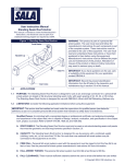
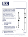
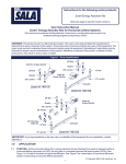
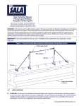
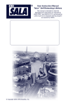
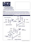
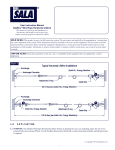
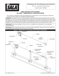
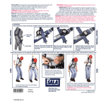
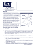
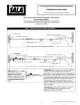
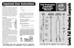
Instructions for the following series products:
Sayfline™ Multi-span Wire Rope Horizontal Lifeline
(See back page for specific model numbers.)
User Instruction ManualSayfline™ Multi-span Wire Rope
Horizontal Lifeline
This manual is provided as the Manufacturer’s Instructions, and should be used as part
of an employee training program as required by OSHA.
WARNING: This product is part of a fall protection system. The users must read and follow the manufacturer’s instructions
for each component of the system. These instructions must be provided to the users of this equipment. The users must
read and understand these instructions before using this equipment. Manufacturer’s instructions must be followed for
proper use and maintenance of this product. Alterations or misuse of this product, or failure to follow instructions, may
result in serious injury or death.
IMPORTANT: If you have questions on the use, care, or suitability of this equipment for your application, contact
DBI/SALA.
Figure 1 - Typical Sayfline™ Multi-span Wire Rope Horizontal Lifeline System
Anchorage
Anchorage Connector
(Supplied by customer)
Turnbuckle
Labels
Zorbit HLL Energy
Absorber
Intermediate
Bracket
Cable
Sayflink Sleeve
Thimble/Cable Clip
End Termination
1.0
APPLICATION
1.1
PURPOSE: The Sayfline Multi-span Wire Rope Horizontal Lifeline System is designed for use as an anchoring
means for one or two personal fall arrest system (PFAS) or fall restraint system. Use the Sayfline Horizontal
Lifeline (HLL) where horizontal mobility and fall protection is required. The Sayfline Horizontal Lifeline may not be
used for fall protection of material or equipment.
1.2
LIMITATIONS: The following limits apply to the installation and use of Sayfline Multi-span Wire Rope Horizontal
Lifeline System. Other limitations may apply:
IMPORTANT: OSHA regulations state that horizontal lifelines shall be installed and used under the supervision of a
qualified person (see below for definition) as part of a complete personal fall arrest system that maintains a safety
factor of at least two.
Qualified Person: An individual with a recognized degree or professional certificate, and extensive knowledge
and experience in the subject field, who is capable of design, analysis, evaluation, and specification in the
subject work, project, or product. Refer to OSHA 1910.66, 1926.32, and 1926.502.
1
© Copyright 2005, DB Industries, Inc.
A. HORIZONTAL LIFELINE SPAN: The maximum horizontal lifeline total length is 180 ft. with a Zorbit HLL
energy absorber installed on each end of the system. See Figure 1. Systems that are more than 30 ft. in
length must include an intermediate bracket for every 30 ft. span. The span length must be reduced when
clearance is limited. See section 3.3 for clearance information.
B. ANCHORAGES: The Sayfline horizontal lifeline must be installed on anchorages that meet the requirements
specified in section 2.5.
C. SYSTEM CAPACITY: The maximum capacity of the Sayfline horizontal lifeline is two persons. The maximum
weight of each person, including tools and clothing, is 310 lbs.
D. CONNECTING SUBSYSTEM: Each person’s connecting subsystem must limit fall arrest forces to 900 lbs. or
less. See section 2.6.
E. FREE FALL: Rig and use the personal fall arrest system such that the maximum potential free fall does not
exceed government regulatory and subsystem manufacturer’s requirements. The personal fall arrest system
must be rigged to limit free falls to six feet or less when using an energy absorbing lanyard, or such that the
SRL is overhead and without slack, according to OSHA requirements. See section 3.0 and subsystem
manufacturer’s instructions for more information.
Figure 2 - Swing Falls
F. SWING FALLS: See Figure 2. Swing falls occur when the
anchorage point is not directly overhead. The force of striking an
object in a swing fall may cause serious injury or death. Minimize
swing falls by working as directly below the anchorage point as
possible. Do not permit a swing fall if injury could occur. Swing falls
will significantly increase the clearance required when a self
retracting lifeline or other variable length connecting subsystem is
used. If a swing fall situation exists in your application, contact DBI/
SALA before proceeding.
G. FALL CLEARANCE: There must be sufficient clearance below the
worker to arrest a fall before striking the lower level or obstruction.
See section 3.3 for required clearance information.
H. BODY SUPPORT: Sayfline Multi-span Wire Rope Horizontal Lifelines must only be used with personal fall
arrest systems incorporating a full body harness.
I.
PHYSICAL AND ENVIRONMENTAL HAZARDS: Use of this equipment in areas with physical or
environmental hazards may require additional precautions to reduce the possibility of injury to the user or
damage to the equipment. Hazards may include, but are not limited to; heat, chemicals, corrosive
environments, high voltage power lines, gases, moving machinery, and sharp edges. Contact DBI/SALA if
you have questions about using this equipment where physical or environmental hazards exist.
J. TRAINING: This equipment must be installed and used by persons trained in the correct application and use
of this equipment. See section 5.0.
1.3
2.0
APPLICABLE STANDARDS: Refer to national standards, including ANSI Z359.1-1992, and local, state, and
federal (OSHA 1910.66 and 1926.502) requirements for more information on personal fall arrest systems and
associated components.
SYSTEM REQUIREMENTS
2.1
PERSONAL FALL ARREST SYSTEM COMPONENTS: The Sayfline horizontal lifeline must be used with
DBI/SALA approved components and subsystems. Non-approved components may be incompatible, and could
affect the safety and reliability of the complete system. Personal fall arrest components used with this system
must meet all applicable OSHA and ANSI requirements. A full body harness must be used with this system. The
connecting subsystem between the harness and horizontal lifeline must limit fall arrest forces to 900 lbs. or less.
2.2
COMPATIBILITY OF CONNECTORS: Connectors are considered to be compatible with connecting elements
when they have been designed to work together in such a way that their sizes and shapes do not cause their gate
2
mechanisms to inadvertently open regardless of how they become oriented. Contact DBI/SALA if you have any
questions about compatibility.
Connectors (hooks, carabiners, and D-rings) must be capable of supporting at least 5,000 lbs. (22kN). Connectors
must be compatible with the anchorage or other system components. Do not use equipment that is not compatible.
Non-compatible connectors may unintentionally disengage. See Figure 3. Connectors must be compatible in size,
shape, and strength. Self locking snap hooks and carabiners are required by ANSI Z359.1 and OSHA.
Figure 3 - Unintentional Disengagement (Roll-out)
If the connecting element that a snap hook (shown) or carabiner attaches to is undersized or irregular in
shape, a situation could occur where the connecting element applies a force to the gate of the snap hook or
carabiner. This force may cause the gate (of either a self-locking or a non-locking snap hook) to open, allowing
the snap hook or carabiner to disengage from the connecting point.
Small ring or other
non-compatibly
shaped element
1. Force is applied to the
snap hook.
2.3
2. The gate presses against
the connecting ring.
3. The gate opens allowing the
snap hook to slip off.
MAKING CONNECTIONS: Only use self-locking snap hooks and carabiners with this equipment. Only use
connectors that are suitable to each application. Ensure all connections are compatible in size, shape and
strength. Do not use equipment that is not compatible. Ensure all connectors are fully closed and locked.
DBI/SALA connectors (snap hooks and carabiners) are designed to be used only as specified in each product’s
user’s instructions. See Figure 4 for inappropriate connections. DBI/SALA snap hooks and carabiners should not
be connected:
Figure 4 - Inappropriate Connections
A. To a D-ring to which another
connector is attached.
B. In a manner that would result in
a load on the gate.
NOTE: Large throat opening snap hooks
should not be connected to standard size
D-rings or similar objects which will result
in a load on the gate if the hook or D-ring
twists or rotates. Large throat snap hooks
are designed for use on fixed structural
elements such as rebar or cross members
that are not shaped in a way that can
capture the gate of the hook.
C. In a false engagement, where features that protrude from the snap hook or carabiner catch on the anchor and
without visual confirmation seems to be fully engaged to the anchor point.
D. To each other.
3
E. Directly to webbing or rope lanyard or tie-back (unless the manufacturer’s instructions for both the lanyard and
connector specifically allow such a connection).
F.
2.4
To any object which is shaped or dimensioned such that the snap hook or carabiner will not close and lock, or
that roll-out could occur.
ANCHORAGE CONNECTORS: DBI/SALA does not supply anchorage fasteners. Connectors used to attach the
horizontal lifeline to end anchors must be compatible with the connection point. The connection must be positive;
and, with connecting elements, capable of sustaining a 5,000 lbs. load without failure.
The intermediate brackets require a 1/2-13 UNC bolt meeting SAE Grade 5 strength minimum. A flat washer, lock
washer and a nut are also required. A locking nut may be used in place of the lock washer and plain nut.
2.5
STRUCTURE LOAD: Structural anchorage points must be rigid, and capable of supporting at least 5,000 lbs. along
the axis of the horizontal lifeline. Anchorages, including the intermediate brackets, must also support at least 3,600 lbs.
applied in all potential directions of fall arrest that are perpendicular to the axis of the horizontal lifeline. See Figure 5.
WARNING: Anchorages must be rigid. Large deformations of the anchorage will affect system performance, and may
increase the required fall clearance below the system, which could result in serious injury or death.
2.6
3.0
3.1
Figure 5 -subsystem
AnchorageisStrength
CONNECTING SUBSYSTEM: The connecting
the portion of the personal fall arrest system that is
used to connect between the horizontal lifeline subsystem and harness fall arrest attachment element. The
connecting subsystem must limit forces applied to the horizontal lifeline to 900 lbs. or less.
INSTALLATION
Inspection
Upon receipt of the Sayfline Horizontal Lifeline System, inspect all components and user equipment for defects
and/or damage. If any Sayfline components or DBI/SALA equipment are found to be damaged, defective, or
missing, contact DBI/SALA immediately for replacements. Do not use any defective or damaged parts in a
Sayfline Horizontal Lifeline System installation.
WARNING: Use of defective or damaged parts will hinder the performance of the Sayfline system, potentially causing
serious injury or death in the event of a fall.
3.2
Safety
A separate means of fall protection must be utilized during the installation of a Sayfline System. A separate
means of fall protection must be used when inspecting or servicing a Sayfline System following a fall.
DBI/SALA recommends the use of certified eye protection, steel toe boots and gloves be worn during the
installation of the horizontal lifeline system.
4
WARNING: Do not alter or intentionally misuse this equipment. Use caution when using this equipment around moving
machinery, electrical and chemical hazards, and sharp edges.
3.3
SYSTEM INSTALLATION:
Figure 1 shows a typical horizontal lifeline system installation. When using an energy absorbing lanyard to
connect to the system, the anchorages must be located at a height above the working level which will limit the
free fall to six feet. The length of the lanyard must be considered when determining the height of the anchorages.
When using a self retracting lifeline (SRL) to connect to the system, the end anchorages must be located above
the user. The SRL, when fully retracted, must be above the harness attachment level. The horizontal lifeline
system should be positioned at a level that will minimize free fall while allowing ease of use.
The horizontal lifeline should be positioned near the work location to minimize swing fall hazards. The connecting
subsystem length should be kept as short as possible to reduce the potential free fall and required clearance distance.
Both anchorages must be installed at approximately the same elevation, so that the horizontal lifeline system is
not sloped more than a 1:12 pitch (1 inch rise over a 12 inch run). The cable must be in a straight line; no curves
or turns are allowed in a Sayfline Multi-span Lifeline installation.
The installation process consists of 7 steps:
1. Determine the location of end anchors and intermediate brackets.
2. Determine the orientation of the intermediate brackets
3. Attach one end to its anchor point.
4. Install cable guides and Sayflink sleeves onto the cable.
5. Assemble intermediate brackets into their anchor points.
6. Unthread turnbuckle(s)
7. Attach the other cable end to its anchor point and tension the cable
The steps are described in detail below:
Step 1.
Determine the locations of the end anchorages and evaluate their strengths in accordance with section
2.4. Determine the number of intermediate brackets necessary for your application. There must be one
intermediate bracket for every 30 feet of cable for systems over 30 feet in length. Additional
intermediate brackets (Part No. 7608001) may be purchased from DBI/SALA. Use Figures 6 and 7 to
Figure 6 - Lanyard Clearance Requirements
5
determine the span length and evaluate the required clearance. Figures 6 and 7 apply to one or two
users connected to the system.
Figure 7 - Self Retracting Lifeline Clearance Requirements
Step 2.
Determine the correct orientation of the intermediate brackets. Depending on the positioning of the
cable, the intermediate brackets may be installed in one of three orientations. See Figure 8 for the
bracket orientations.
Note: A maximum free fall distance of 6 ft. must be maintained in all bracket positions; a system with
brackets mounted below the user should only be used for fall restraint applications.
Figure 8 - Bracket Orientations
Overhead
Step 3.
At an angle
To the side
Below
To attach the cable to the first anchor point, link one pair of shackles together, then connect one side of
the linked shackles to the anchor using the included nut and bolt. Connect the other side of the
shackles to the Zorbit that’s connected to the turnbuckle. See Figure 9. The horizontal lifeline system
may be secured directly to the anchorage if the anchorage incorporates a connecting element that
meets the requirements specified in section 2.4. The user must supply the anchorage hardware.
Tighten bolts and nuts used to connect the system to the anchorage connectors. Slide the Sayflink
6
sleeve(s) onto the lifeline before terminating the other
end of the cable to the anchor.
Figure 9 - Cable Termination
Shackles
Step 4.
If additional intermediate brackets are purchased,
slide all of the cable guides from the brackets onto
the cable before installing the cable.
Zorbit Shock
Absorber
Turnbuckle
Step 5.
The intermediate brackets are composed of three
parts: two side plates and a cable guide. Each of the
plates is stamped with the letter “A” or “B”. See
Figure 10. To assemble a bracket, start by placing a
cable guide into Part A at the appropriate angle as
determined in Step 2. Then slide Part B onto the
cable guide at the same angle and nestle Part B
Figure 10 - Bracket Assembly
into Part A. Place the assembled bracket at its
designated anchor point and anchor it by placing
Part A
the user supplied bolt through a flat washer and
then though the mated holes in the bracket and
Part B
into the anchor point. The bolt may be installed
through the anchor and into the bracket if
preferred, but the washer must remain inside the Cable Guide
bracket, between the bracket and the bolt head
or nut. Torque the anchor hardware to 55 ft./lbs.
Step 6.
Before terminating the second end of the
horizontal lifeline, unthread the turnbuckle on the
first end so that only four threads are visible
inside the turnbuckle body. This will allow for
maximum tensioning of the system after
anchoring the second end. Install all of the
Sayflink sleeves onto the cable before terminating the second end.
Step 7.
To terminate the second end of the cable to its anchor, attach the shackles to the anchor and Zorbit as
described in Step 3. Then attach the thimble and connecting hardware to the Zorbit. See Figure 11.
Slide the lifeline through the thimble. Remove excess slack by pulling the wire rope through the thimble
and cable clip. Maintain tension while torquing the cable clip nut and the thimble clip nut to the values
specified in Figure 11. Tension the wire rope by turning the turnbuckle at the other end of the installation.
The unrestrained turnbuckle jaw end must be prevented from turning to prevent twisting the wire rope.
The wire rope must be tensioned until the sag on the system at mid-span, between intermediate
brackets, is two inches or less, with no weight on the wire rope.
Figure 11 - Thimble/Cable Clip End Termination
Sayfline Wire Rope HLL System End Termination
Cable Clip
Torque to 45 ft/lbs
Thimble/Cable Clip
Torque to 40 ft/lbs
7
4.0
OPERATION AND USE:
WARNING: Consult your doctor if there is reason to doubt your fitness to absorb the impact from a fall arrest. Age and
fitness can affect your ability to withstand fall arrest forces. Pregnant women and minors must not use the Sayfline
Multi-span Wire Rope Horizontal Lifeline System.
4.1
BEFORE EACH USE inspect this equipment according to steps listed in section 6.4. Do not use this equipment if
inspection reveals an unsafe or defective condition. Plan your use of the fall protection system prior to
exposing workers to dangerous situations. Consider all factors affecting your safety before using this system.
A. Read and understand all manufacturer’s instructions for each component of the personal fall arrest system. All
DBI/SALA harnesses and connecting subsystems are supplied with separate user instructions. Keep all
instructions for future reference.
B. Review sections 1.0 and 2.0 to ensure system limitations and other requirements have been adhered to.
Review applicable information regarding system clearance criteria, and ensure changes have not been made
to the system installation (i.e. length), or occurred at the job site, that could affect the required fall clearance.
Do not use the system if changes are required.
4.2
USE OF THE SYSTEM:
A. PERSONAL FALL ARREST SYSTEM COMPONENTS: Inspect and don the full body harness according to
manufacturer’s instructions. Attach the connecting subsystem (energy absorbing lanyard or self retracting
lifeline) to the dorsal connection on the harness. If a self retracting lifeline (SRL) is used, DBI/SALA recommends
using SRLs that are 20 feet long or shorter. The weight of longer SRLs may cause the Sayflink sleeve to
catch on intermediate brackets, causing the lifeline to extend which may result in an unexpected swing fall.
WARNING: If the Sayflink sleeve catches on an intermediate bracket, the SRL lifeline may extend while the worker moves
along the HLL. This will increase fall distance and create a swing fall hazard which may result in serious injury or death.
B. CONNECTING TO THE HLL SYSTEM: Approach the work area using the appropriate access equipment.
Connect the personal fall arrest system to one of the D-rings on a Sayflink sleeve on the HLL. Connectors
must meet all compatibility and strength requirements.
C. WALKING ALONG THE SYSTEM: Once attached to the Sayfline System, the Sayflink Sleeve will follow the
user along the lifeline and will automatically pass over each intermediate support bracket.
WARNING: Movement along the Sayfline System must be done manually by the user of the system. Never allow moving
stock (such as railcars) to move the user along the Sayfline System. This could cause serious injury or death.
D. HAZARDOUS SITUATIONS: Do not take unnecessary risks, such as jumping or reaching too far from the
edge of the working surface. Do not allow the connecting subsystem to pass under arms or between feet. To
avoid inadequate fall clearance, do not climb above the HLL. To avoid swing fall hazards, do not work too far
from either side of the HLL.
E. TWO PERSONS CONNECTED TO THE HLL: When a person falls while connected to the HLL, the system
will deflect. If two persons are connected to the same HLL, and one person falls, the second person may be
pulled off the working surface due to deflection. The potential for the second person falling increases as the
HLL span length increases. The use of independent HLL systems for each person, or shorter span length, is
recommended to minimize the potential of the second person falling.
F. FREE FALL: The personal fall arrest system must be rigged to limit free falls to six feet or less when using an
energy absorbing lanyard, or such that the SRL is overhead and without slack, according to OSHA requirements.
G. SHARP EDGES: Avoid working where the connecting subsystem or other system components will be in
contact with, or abrade against, unprotected sharp edges. If working around sharp edges is unavoidable,
provide protection by securing a heavy pad or other means over the exposed edge.
H. IN THE EVENT OF A FALL: The responsible party must have a rescue plan and the ability to implement a
8
rescue. Tolerable suspension time in a full body harness is limited, so a prompt rescue is critical.
IMPORTANT: Use care when handling an expended Zorbit energy absorber. The tearing of the energy absorber material
produces extremely sharp edges.
I.
4.3
5.0
5.1
6.0
RESCUE: With the number of potential scenarios for a worker requiring rescue, an on site rescue team is
beneficial. The rescue team is given the tools, both in equipment and techniques, so it can perform a
successful rescue. Training should be provided on a periodic basis to ensure rescuers’ proficiency.
SYSTEM REMOVAL: When no longer required, the HLL system should be removed from the job site. To
slacken the HLL, loosen the turnbuckle until tension is removed from the wire rope. Disconnect the HLL system
from the anchorages. Ensure there are no knots or kinks in the wire rope before storage.
TRAINING
It is the responsibility of all users of this equipment to understand these instructions, and to be trained in the
correct installation, use, and maintenance of this equipment. These individuals must be aware of the
consequences of improper installation or use of this equipment. This user manual is not a substitute for a
comprehensive training program. Training must be provided on a periodic basis to ensure proficiency of the
users.
INSPECTION
6.1
BEFORE EACH INSTALLATION: Inspect the Zorbit HLL energy absorbers, kit components, and other system
components according to these or other manufacturer’s instructions. System components must be formally
inspected by a qualified person (other than the user). Formal inspections should concentrate on visible signs of
deterioration or damage to the system components. Items found to be defective must be replaced. Do not use
components if inspection reveals an unsafe or defective condition. Record results of each inspection in the
inspection and maintenance log in section 11.0 of this manual.
6.2
INSTALLED SYSTEMS: An inspection of the HLL system by a qualified person must be completed after the
system is installed. The system must be periodically inspected by a qualified person when left installed for an
extended period. Periodic inspections should be performed at least monthly, or more frequently when site
conditions and use warrant. Inspections of installed systems should include the inspection steps listed in
section 6.4.
6.3
Annually: A Qualified Person shall inspect the entire system including the anchorage points. Inspect for
deterioration or damage. Items found to be defective must be replaced. Do not use components if inspection
reveals an unsafe or defective condition. Record the results of each inspection in the Inspection and Maintenance
Log in section 11.0 of this manual.
6.4
BEFORE SYSTEM USE:
Step 1. Inspect the turnbuckle for damage. Ensure at least four threads are visible inside the
turnbuckle body. Look for any cracks or deformities in the metal. Inspect metal components for rust or
corrosion that may affect their strength or operation.
Step 2. Inspect the wire rope for rust, corrosion, broken wires, or other obvious faults. Inspect the HLL
for proper tension. Inspect all hardware (fasteners, shackles, wire rope cable clips, etc.) securing the
HLL assembly to ensure they are present and properly installed.
Step 3. Inspect the Sayflink Sleeve for excessive wear, damage, or corrosion.
Step 4. Inspect the Zorbit HLL energy absorber for extension or deformities. There should be no
tearing of the metal between holes in the Zorbit coiled section. Extended Zorbit HLL energy absorbers
must be removed from service and destroyed, or marked for training only. Inspect securing hardware for
strength and function.
9
Step 5. Inspect the intermediate brackets for wear or damage. Check brackets to make certain they
are securely attached. Make certain all installed Sayflink sleeves pass freely through the intermediate
brackets when moving along the system during normal use.
Step 6. Inspect system labels. The labels must be present and fully legible. See section 9.0. Replace
labels if missing or illegible.
IMPORTANT: If this equipment is subjected to the forces of a fall arrest, it must be removed from service and
destroyed, or returned to DBI/SALA for inspection or repair.
6.5
If inspection reveals an unsafe or defective condition, remove unit from service and destroy, or contact DBI/SALA
for possible repair.
6.6
USER EQUIPMENT: Inspect harnesses and energy absorbing lanyards or SRL’s used with the HLL system
according to manufacturer’s instructions.
7.0
MAINTENANCE, SERVICE, STORAGE
7.1
MAINTENANCE: The Sayfline components require no scheduled maintenance, other than repair or replacement of
items found defective during inspection. See section 6.0.
7.2
CLEANING: If components become heavily soiled with grease, paint, or other substances, clean with appropriate
cleaning solutions.
Remove dirt from the cable using a fiber brush. Do not use a wire brush and do not apply any solvents or
lubricants without prior approval from DBI/SALA.
Clean all other Sayfline components using a nonabrasive cloth and hot water/mild detergent mix. Dry with a clean
cloth. Do not use solvents to clean any Sayfline Component. Do not use caustic chemicals that could damage
system components.
7.3
8.0
8.1
USER EQUIPMENT: Maintain, service, and store system components according to manufacturer’s instructions
for each component.
SPECIFICATIONS
MATERIALS:
Zorbit Energy Absorber: Stainless steel
Wire Rope: 3/8 inch diameter, 7x19 galvanized steel
Bolts: Grade 5 or Grade 8 zinc plated steel
Nuts: Zinc plated steel
Intermediate Brackets: 11 ga. hot rolled steel, zinc plated
Sayflink Sleeve Assembly: alloy steel
Shackles: Galvanized steel, 5,000 lbs. minimum tensile strength
Thimbles: Galvanized steel
Turnbuckle: Galvanized steel, 5,000 lbs. minimum tensile strength
Cable Clips: Galvanized steel
8.2
ENERGY ABSORBER PERFORMANCE:
Peak Dynamic Pullout Load: 2,500 lbs.
Average Dynamic Pullout Load: 2,000 lbs.
Maximum Pullout: 48.5 inches
Minimum Tensile Strength: 5,000 lbs.
Patents Pending
10
9.0
9.1
LABELING
These labels must be present and fully legible:
Zorbit Label:
Sayfline Labels:
11
10.0
COMPONENT DRAWINGS:
Zorbit - Part No. 7401013
12
Sayflink Sleeve Assembly - Part No. 768002
13
Intermediate Bracket - Part No. 7608001
Turnbuckle - Part No. 7002050
14
11.0
INSPECTION AND MAINTENANCE LOG
DATE OF MANUFACTURE: _______________________________________________________________________
MODEL NUMBER: ______________________________________________________________________________
DATE PURCHASED: ________________________________________________________________________________
INSPECTION DATE
INSPECTION ITEMS
NOTED
CORRECTIVE ACTION
Approved By:
Approved By:
Approved By:
Approved By:
Approved By:
Approved By:
Approved By:
Approved By:
Approved By:
Approved By:
Approved By:
Approved By:
15
MAINTENANCE
PERFORMED
This instruction applies to the following models:
7603000
7603020
7603040
7603060
7603080
7603100
7603120
7603140
7603160
7603180
7603200
7603220
7608001
Additional model numbers may appear on the next printing of these instructions
USA
Canada
3965 Pepin Avenue
Red Wing, MN 55066-1837
Toll Free: 800-328-6146
Phone: (651) 388-8282
Fax: (651) 388-5065
www.salagroup.com
260 Export Boulevard
Mississauga, Ontario L5S 1Y9
Toll Free: 800-387-7484
Phone: (905) 795-9333
Fax: (905) 795-8777
www.salagroup.com
This manual is available for download at www.salagroup.com.
I S O
9001
Certificate No. FM 39709
16
Form: 5902167
Rev: C