1
USER MANUAL
SecureMag
Encrypted
MagStripe Reader
USB, RS232 and PS2 Interface
80096504-001
Rev D 06/27/11
SecureMag User Manual
FCC WARNING STATEMENT
This equipment has been tested and found to comply with the limits for a Class B digital
device, pursuant to Part 15 of FCC Rules. These limits are designed to provide reasonable
protection against harmful interference when the equipment is operated in a commercial
environment. This equipment generates, uses, and can radiate radio frequency energy and,
if not installed and used in accordance with the instruction manual, may cause harmful
interference to radio communications. Operation of this equipment in a residential area is
likely to cause harmful interference in which case the user will be required to correct the
interference at his expense.
FCC COMPLIANCE STATEMENT
This device complies with Part 15 of the FCC Rules. Operation of this device is subject to
the following conditions: this device may not cause harmful interference and this device
must accept any interference received, including interference that may cause undesired
operation.
CANADIAN DOC STATEMENT
This digital apparatus does not exceed the Class B limits for radio noise for digital
apparatus set out in the Radio Interference Regulations of the Canadian Department of
Communications.
Le présent appareil numérique n’émet pas de bruits radioélectriques dépassant les limites
applicables aux appareils numériques de las classe A prescrites dans le Réglement sur le
brouillage radioélectrique édicté par les ministère des Communications du Canada.
CE STANDARDS
An independent laboratory performed testing for compliance to CE requirements. The unit
under test was found compliant to Class B.
Copyright © 2010-2011, International Technologies & Systems Corp. All rights reserved.
Page 2 of 72
SecureMag User Manual
LIMITED WARRANTY
ID TECH warrants to the original purchaser for a period of 12 months from the date of
invoice that this product is in good working order and free from defects in material and
workmanship under normal use and service. ID TECH’s obligation under this warranty is
limited to, at its option, replacing, repairing, or giving credit for any product that returned
to the factory of origin with the warranty period and with transportation charges and
insurance prepaid, and which is, after examination, disclosed to ID TECH’s satisfaction to
be defective. The expense of removal and reinstallation of any item or items of equipment
is not included in this warranty. No person, firm, or corporation is authorized to assume for
ID TECH any other liabilities in connection with the sales of any product. In no event shall
ID TECH be liable for any special, incidental or consequential damages to purchaser or any
third party caused by any defective item of equipment, whether that defect is warranted
against or not. Purchaser’s sole and exclusive remedy for defective equipment, which does
not conform to the requirements of sales, is to have such equipment replaced or repaired by
ID TECH. For limited warranty service during the warranty period, please contact ID
TECH to obtain a Return Material Authorization (RMA) number & instructions for
returning the product.
THIS WARRANTY IS IN LIEU OF ALL OTHER WARRANTIES OF
MERCHANTABILITY OR FITNESS FOR PARTICULAR PURPOSE. THERE ARE NO
OTHER WARRANTIES OR GUARANTEES, EXPRESS OR IMPLIED, OTHER THAN
THOSE HEREIN STATED. THIS PRODUCT IS SOLD AS IS. IN NO EVENT SHALL
ID TECH BE LIABLE FOR CLAIMS BASED UPON BREACH OF EXPRESS OR
IMPLIED WARRANTY OF NEGLIGENCE OF ANY OTHER DAMAGES WHETHER
DIRECT, IMMEDIATE, FORESEEABLE, CONSEQUENTIAL OR SPECIAL OR FOR
ANY EXPENSE INCURRED BY REASON OF THE USE OR MISUSE, SALE OR
FABRICATIONS OF PRODUCTS WHICH DO NOT CONFORM TO THE TERMS
AND CONDITIONS OF THE CONTRACT.
The information contained herein is provided to the user as a convenience. While every
effort has been made to ensure accuracy, ID TECH is not responsible for damages that
might occur because of errors or omissions, including any loss of profit or other
commercial damage, nor for any infringements or patents or other rights of third parties
that may result from its use. The specifications described herein were current at the time of
publication, but are subject to change at any time without prior notice.
ID TECH and Value through Innovation are trademarks of International Technologies &
Systems Corporation. USB (Universal Serial Bus) specification is copyright by Compaq
Computer Corporation, Intel Corporation, Microsoft Corporation, and NEC Corporation.
Windows is registered trademarks of Microsoft Corporation.
ID TECH
10721 Walker Street
Cypress, CA 90630
(714) 761-6368
Copyright © 2010-2011, International Technologies & Systems Corp. All rights reserved.
Page 3 of 72
SecureMag User Manual
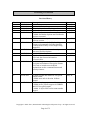
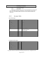
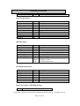
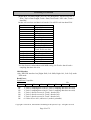
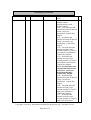
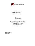
Revision History
Revision
A
A1
A2
A3
A4
Date
05/05/2010
06/14/2010
06/16/2010
06/25/2010
06/28/2010
A5
06/29/2010
A6
07/21/2010
A7
09/07/2010
A8
A9
09/07/2010
09/10/2010
B
09/24/2010
C
05/02/2011
D
06/27/2011
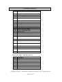
Description
Initial Release
Added RS232 interface
General edits and modified Appendix A
Updated reader command summary
Updated reader command.
- Added Set Reader Options and Get Reader
Options command
Added level 4 security features to demo
software section
- Modified commands for Key Loading
- Removed commands for Enter/Quit Key
Loading mode as they are no longer being
supported
Added original and enhanced security
structures and descriptions
Added PS2 interface
- Updated demo software screenshots.
- Revised data format information.
- General edits.
- Added decryption example for level 3 and
4 original and enhanced encryption format.
- Revised to include more detailed
explanations on the command format and
security features
- Edited original and enhanced encryption
output format
- Added more info in Section 10 Data
Output.
- Updated setting parameters table
- Added prefix, postfix support in USBKB
and PS2 encrypted output.
- Added 19 bytes ISO card account number
support
By
Jenny W
Jenny W
Jenny W
Jenny W
Jenny W
Jenny W
Jenny W
Bruce K
Jimmy W
Jenny W
Jenny W
Jenny W
Jenny W
Copyright © 2010-2011, International Technologies & Systems Corp. All rights reserved.
Page 4 of 72
SecureMag User Manual
Table of Contents
Introduction ................................................................................................................... 7
Features and Benefits .................................................................................................... 7
Terms and Abbreviations .............................................................................................. 8
Applicable Documents .................................................................................................. 9
Operation..................................................................................................................... 10
Specification ............................................................................................................... 11
Command Process ....................................................................................................... 14
7.1 Get Copyright Information .................................................................................... 15
7.2 Version Report Command ..................................................................................... 16
7.3 Key Loading Command ........................................................................................ 16
7.4 Reader Reset Command ........................................................................................ 18
7.5 OPOS/JPOS Command ......................................................................................... 18
7.6 Arm/Disarm to Read Command ............................................................................ 18
7.7 Read Buffered MSR Data Command .................................................................... 19
7.8 Read MSR Options Command .............................................................................. 19
7.9 Set MSR Options Command ................................................................................. 20
7.9.1.
Beep Volume ....................................................................................................20
7.9.2.
Change to Default Settings ...............................................................................20
7.9.3.
MSR Reading Settings ......................................................................................20
7.9.4.
Decoding Method Settings ................................................................................20
7.9.5.
Terminator Setting ............................................................................................21
7.9.6.
Preamble Setting ...............................................................................................21
7.9.7.
Postamble Setting..............................................................................................21
7.9.8.
Track n Prefix Setting .......................................................................................21
7.9.9.
Track x Suffix Setting .......................................................................................22
7.9.10. Track Selection .................................................................................................22
7.9.11. Track Separator Selection .................................................................................23
7.9.12. Start/End Sentinel and Track 2 Account Number Only....................................23
8. Security Features ......................................................................................................... 24
8.1
Encryption Management ...................................................................................25
8.2
Check Card Format ...........................................................................................25
8.3
MSR Data Masking...........................................................................................25
9. Using the Demo Program............................................................................................ 27
9.1 Manual Command ................................................................................................. 28
9.2 Decryption ............................................................................................................. 29
9.3 Reader Operations ................................................................................................. 31
10. Data Format ................................................................................................................ 32
10.1
Level 1 and level 2 Standard Mode Data Output Format .................................. 32
10.1.1.
USB HID Data Format................................................................................... 33
10.1.2.
Descriptor Tables ........................................................................................... 34
10.2
Level 1 and level 2 POS Mode Data Output Format ......................................... 37
10.3
DUKPT Level 3 Data Output Enhanced Format ............................................... 40
10.4
DUKPT Level 3 Data Output Original Format ................................................. 43
10.5
DUKPT Level 4 Data Output Original Format ................................................. 44
1.
2.
3.
4.
5.
6.
7.
Copyright © 2010-2011, International Technologies & Systems Corp. All rights reserved.
Page 5 of 72
SecureMag User Manual
10.6
Decryption Example .......................................................................................... 48
10.6.1.
Security Level 3 Decryption - Original Encryption Format .......................... 48
10.6.2.
Security Level 4 Decryption - Original Encryption Format .......................... 50
10.6.3.
Security Level 3 Decryption - Enhanced Encryption Format ........................ 51
10.6.4.
Security Level 4 Decryption – Enhanced Encryption Format ....................... 54
10.7
Level 4 Activate Authentication Sequence ....................................................... 55
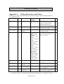
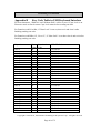
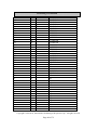
Appendix A Setting Parameters and Values ................................................................... 59
Appendix B
Key Code Table in USB Keyboard Interface ............................................. 66
Copyright © 2010-2011, International Technologies & Systems Corp. All rights reserved.
Page 6 of 72
SecureMag User Manual
1. Introduction
ID TECH SecureMag reader delivers superior reading performance with the ability to
encrypt sensitive card data. The data encryption process prevents card holder information
from being accessed when the data is stored or in transit, so the data remains secure from
end to end. The reader fully supports TDES and AES data encryption using DUKPT key
management method. The SecureMag is offered in USB, RS232 as well as PS2 interfaces.
2. Features and Benefits
Bi-directional card reading
Reads encoded data that meets ANSI/ISO/AAMVA standards and some
custom formats such as ISO track 1 format on track 2 or 3
Reads up to three tracks of card data
A LED and a beeper on the reader provide status of the reading operations
Compatible with USB specification Revision 2.0 (USB interface)
Compatible with HID specification Version 1.1 (USB interface)
Uses standard Windows HID driver for communications; no third party
device driver is required (USB interface)
Provides clear text confirmation data including card holder’s name and a
portion of the PAN as part of the Masked Track Data
User friendly configuration software for device configuration
Copyright © 2010-2011, International Technologies & Systems Corp. All rights reserved.
Page 7 of 72
SecureMag User Manual
3. Terms and Abbreviations
AAMVA American Association of Motor Vehicle Administration
ABA
American Banking Association
AES
Advanced Encryption Standard
ASIC
Application Specific Integrated Circuit
BPI
Bits per Inch
CADL California Drivers License Format (obsolescent)
CE
European Safety and Emission approval authority
COM
serial communication
CTS
Clear-To-Send
CDC
USB to serial driver (Communication Device Class)
DES
Data Encryption Standard
DUKPT Derived Unique Key Per Transaction
DMV
Department of Motor Vehicle
GND
Signal Ground
HID
Human Interface Device
IPS
Inches per Second
ISO
International Organization for Standardization
JIS
Japanese Industrial Standard
JPOS
Java for Retail Point Of Sale
KB
Keyboard
KSN
Key Serial Number
LED
Light Emitting Diode
LRC
Longitudinal Redundancy Check Character.
MAC
Message Authentication Code
MSR
Magnetic Stripe Reader
OLE
Object Linking and Embedding
OPOS
OLE for Retail Point Of Sale
OTP
One Time Programmable
PAN
Primary account number
PCI
Payment Card Industry
PID
USB Product ID
POS
Point of Sale
PPMSR Serial Port Power Magstripe Reader
P/N
Part Number
PS/2
IBM Personal System/2 Keyboard Interface
RTS
Request To Send
SPI
Serial Peripheral Interface
T1, T2, T3
Track 1 data, Track 2 data, Track 3 data
TDES
Triple Data Encryption Standard
VID
USB Vendor ID
Note: many unusual words used in this document are defined in the Function ID
table on page.
Copyright © 2010-2011, International Technologies & Systems Corp. All rights reserved.
Page 8 of 72
SecureMag User Manual
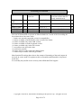
4. Applicable Documents
ISO 7810 – 1985
ISO 7811 - 1 through 6
ISO 7816 - 1 through 4
ISO 4909
ISO 7812
ISO 7813
ANSI X.94
Identification Cards – Physical
Identification Cards - Track 1 through 3
Identification Cards - Integrated circuit cards with contacts
Magnetic stripe content for track 3
Identification Cards – Identification for issuers Part 1 & 2
Identification Cards – Financial Transaction Cards
Retail Financial Services Symmetric Key Management
Copyright © 2010-2011, International Technologies & Systems Corp. All rights reserved.
Page 9 of 72
SecureMag User Manual
5. Operation
A card may be swiped through the reader slot when the LED is green. The magnetic
stripe must face toward the magnetic read head and may be swiped in either direction.
After a card is swiped, the LED will turn off temporarily until the decode process is
completed. If there are no errors decoding the card data then the LED will turn green. If
there are any errors decoding the card data, the LED will turn red for less than one second
to indicate that an error occurred and then turn green.
The reader LED will be off during the data transfer and is ready to read another card
when the LED returns to green. A red LED indicates an error and the beeper will also
provide error indications. The beeper will beep for each correctly read track of data on
the magstripe card. Depending on the security level configured, the card data might be
displayed in clear or encrypted mode.
Copyright © 2010-2011, International Technologies & Systems Corp. All rights reserved.
Page 10 of 72
SecureMag User Manual
6. Specification
Power Consumption
•
•
•
•
5VDC +/- 10%
Maximum operating current consumption less than 50mA
RS232 interface – external power adaptor supplies power through RS232 cable
USB interface – from host interface. No external power adaptor needed.
Swipe speed
•
•
3 to 65 inches per second
Bi-directional
Indicators
•
•
Tri-color LED
o Red indicates bad read
o LED off while reading and decoding
o Green indicates good read, and ready to read
Beeper
o A beep sound indicates good read
Communication Interface
•
•
•
RS232
o Baud Rate – 1200, 2400, 4800, 9600, 19200, 38400, 56700, 115200
o Data bits – 8
o Stop bits – 1 or 2
o Parity – off, odd, even, mark or space
o Supports RTS/CTS hardware and Xon-Xoff software handshaking
USB
o Complies with USB 2.0 specification
PS2 Keyboard
o IBM PS2 interface compatible
Card Size
•
Supports cards that meets the ISO 7810 and 7811 1-7 standards
Dimension
•
3.94 inches (length) by 1.38 inches (width) and 1.18 inches (height).
Copyright © 2010-2011, International Technologies & Systems Corp. All rights reserved.
Page 11 of 72
SecureMag User Manual
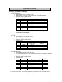
Interface cable and connector
•
RS232 interface
o IDT standard RS232 Interface Cable
o DB-9 Female connector with 2mm power jack in the housing
o Standard cable length is 6 feet
o Pin Out Table
J1*
Color
Signal
P1*
1
CASE_GND
SHELL
2
White
TXD
2
3
Green
RXD
3
4
Yellow
VCC
from power jack
5
Brown
RTS
8**
6
Grey
CTS
4**
7
Black
GND
5
*J1 is the connector to PCB end and P1 is DB-9 end
** RTS and CTS are not used unless hardware handshaking support is enabled by
Function ID 0x44 (Handshake)
•
•
USB
o
o
o
o
IDT standard USB interface cable
Series “A” plug
Standard cable length is 6 feet
Pin Out Table
J1
Color
Signal
1
CASE_GND
3
GRN
+DATA
5
Red
V_IN
6
White
-DATA
7
BLK
GND
P1
SHELL
3
1
2
4
Keyboard wedge
o IDT standard Keyboard Wedge cable
o Y cable with dual PS/2 6-pin mini-DIN connectors; male side is connected
to PC, female side connected to KB.
o Standard cable length is 6 feet
o Pin Out Table
J1
Color
Signal
J2
J3
1
CASE_GND
SHELL SHELL
2
White
P-CLK
5
-3
Green
P-DATA
1
-4
Yellow
VCC
4
4
5
Brown
K-CLK
-5
6
Grey
K-DATA
-1
7
Black
GND
3
3
Copyright © 2010-2011, International Technologies & Systems Corp. All rights reserved.
Page 12 of 72
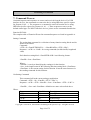
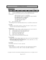
SecureMag User Manual
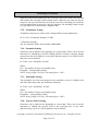
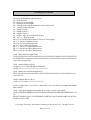
PS/2 Connector
LED indicator
•
2mmx5mm, Green/Red dual color under firmware control
Copyright © 2010-2011, International Technologies & Systems Corp. All rights reserved.
Page 13 of 72
SecureMag User Manual
7. Command Process
Command requests and responses are sent to and received from the device. For USB
interface devices, the commands are sent to the device using HID class specific request
Set_Report (21 09 …). The response to a command is retrieved from the device using
HID class specific request Get_Report (A1 01 …). These requests are sent over the
default control pipe. For RS232 interface devices, please see the commands listed below.
Function ID Table
The complete table of Function ID used in command/response are listed in Appendix A.
Setting Command
The setting data command is a collection of many function setting blocks and its
format is as follows.
Command:
<STX><S><FuncSETBLOCK1>…<FuncBLOCKn><ETX><LRC>
Response: <ACK> or <NAK> for wrong command (invalid funcID, length and
value)
Each function-setting block <FuncSETBLOCK> has following format:
<FuncID><Len><FuncData>
Where:
<FuncID> is one byte identifying the setting(s) for the function.
<Len> is the length count for the following function-setting block <FuncData>.
<FuncData> is the current setting for this function. It has the same format as in
the sending command for this function.
Get Setting Command
This command will send current setting to application.
Command: <STX> <R> <FuncID> <ETX> <LRC 1>
Response: <ACK> <STX> <FuncID> <Len> <FuncData> <ETX> <LRC 2>
<FuncID>, <Len> and <FuncData> definition are same as described above.
Where:
Characters
<STX>
<ETX>
<ACK>
<NAK>
Hex Value
02
03
06
15 for
Description
Start of Text
End of Text
Acknowledge
Negative Acknowledge
Copyright © 2010-2011, International Technologies & Systems Corp. All rights reserved.
Page 14 of 72
SecureMag User Manual
<UnknownID>
<AlreadyInPOS>
RS232 and
USB HID
interface;
FD for USB
KB interface
16
17
<R>
<S>
<LRC>
52
53
-
Reader Command Summary
ASCII
HEX Name
‘8’
38
Copyright Report
‘9’
39
Version Report
‘F”
46
Key Loading
‘I’
49
Reader Reset
‘M’
4D
OPOS/ JPOS Command
‘P’
‘Q’
‘R’
‘S’
50
51
52
53
Arm/Disarm to Read
Read Buffered Data
Read MSR Options
Set MSR Options
Warning: Unsupported ID in setting
Warning: Reader already in OPOS
mode
Review Setting
Send Setting
Xor’d all the data before LRC.
Use
Requests reader’s copyright notice
Requests version string
Special command to load encryption
keys
Reset the reader. Software reset does
not resend startup string
Command to enter OPOS or JPOS
mode
Arm to Capture Buffer Mode MSR
Read Stored MSR Data
Read various reader optional settings
Set various reader optional functions
Notation used throughout the document:
Bold: boldface font indicates default setting value
‘2’: single quotation indicates ASCII characters, for example, ‘2’ is 32 in hex
“Number”: a null terminated character string
<Len>: angle brackets indicate a specific character or character string in a command or
response
Hex: the hex character 53 is ‘5’ in ASCII or 83 in decimal. Sometimes hex characters are
represented with an h attached to the end, for example, 53h.
\02: is a way to show that the following number is in hex. It is used by the configuration
program.
7.1 Get Copyright Information
02 38 03 39
A ‘31-byte’ Copyright Notice will be returned.
Copyright © 2010-2011, International Technologies & Systems Corp. All rights reserved.
Page 15 of 72
SecureMag User Manual
Response is as follows:
ACK STX <Copyright String> ETX LRC
Response Example mixed hex and ASCII:
\06\02Copyright (c) 2010, ID TECH \03>
7.2 Version Report Command
02 39 03 38
Response is as follows:
ACK STX<Version String> ETX LRC
Response Example mixed hex and ASCII:
\06\02ID TECH TM3 SecureMag RS232 Reader V 3.19\03\LRC
7.3 Key Loading Command
Note: This command is normally only used by a key loading facility.
The Encrypted swipe read supports TDES and AES encryption standards for data
encryption. Encryption can be turned on via a command. TDES is the default.
If the reader is in security level 3, for the encrypted fields, the original data is
encrypted using the TDES/AES CBC mode with an Initialization Vector starting at all
binary zeroes and the Encryption Key associated with the current DUKPT KSN.
KSN and Device Key loading commands and responses protocol:
When DUKPT key management is used, it is necessary to load Key Serial Number
(KSN) and Initially Loaded Device Key before transaction.
The encryption key is TDES with 128 bit keys or AES encryption with double length
keys (128 bit keys including parity).
KSN and Device Key loading commands and responses protocol:
Command:
<STX><’F’><’F’><Command Data (BASE64)><0x0D><0x0A><ETX><LRC>
Response:
<ACK/NAK><STX><’F’><’F’>< Respond Data(BASE64)><0x0D><0x0A><ETX>
<LRC>
STX: 0x02
ETX: 0x03
ACK: 0x06
NAK: 0x15
BASE64: Data encoded with base64 algorithm
LRC: Xor’d all the data before LRC.
Copyright © 2010-2011, International Technologies & Systems Corp. All rights reserved.
Page 16 of 72
SecureMag User Manual
A successful key loading process includes the following steps:
• Get Key status
Command Data: <FF><13><01><02><LRC>
Response Data: <FF><00><01><04><LRC>
For Example:
Command: \02\46\46\2F\78\4D\42\41\75\38\3D\0D\0A\03\LRC
Response: \06\02\46\46\...............\0D\0A\03\LRC
• Load KSN
Command Data: <FF><0A><11><KSN#><KSN bytes><LRC>
Response Data: <FF><00><06><RESPONSE CODE><LRC>
<KSN#>: TDES: 0x32 DES: 0x0A
<KSN bytes>: 16 bytes ASCII for KSN
<RESPONSE CODE>: 6 bytes data in ASCII format which is converted from the
first 3 cipher hex data. These cipher data are generated by encrypting KSN bytes and
"00 00 00 00 00 00 00 00".
For Example:
Command:
\02\46\46\2F\77\6F\52\4D\6B\5A\47\52\6B\59\35\4F\44\63\32\4E\54\51\7A\4D\6A\4
5\77\52\54\43\69\0D\0A\03\5D
Response: \06\02\46\46\..............\0D\0A\03\LRC
• Load Encryption Key
Command Data: <FF><0A><LENGTH><KEY#><KEY bytes><LRC>
Response Data: <FF><00><06><RESPONSE CODE><LRC>
<LENGTH>: TDES: 0x21 DES: 0x11
<KEY#>: TDES: 0x33 DES: 0x0B
<KEY bytes>: TDES: 0x20
DES: 0x10
<RESPONSE CODE>: 6 bytes data in ASCII format which is converted from the
first 3 cipher hex data. These cipher data are generated by encrypting KEY bytes and
"00 00 00 00 00 00 00 00".
For Example:
Command:
\02\46\46\2F\77\6F\68\4D\7A\5A\42\51\7A\49\35\4D\6B\5A\42\51\54\45\7A\4D\54\
56\43\4E\45\51\34\4E\54\68\42\51\6A\4E\42\4D\30\51\33\52\44\55\35\4D\7A\4E\42
\6C\51\3D\3D\0D\0A\03\2D
Response: \06\02\46\46\..............\0D\0A\03\LRC
Copyright © 2010-2011, International Technologies & Systems Corp. All rights reserved.
Page 17 of 72
SecureMag User Manual
7.4 Reader Reset Command
02 49 03 48
The reader supports a reset reader command. This allows the host to return the
reader to its default state.
Response is as follows:
06
7.5 OPOS/JPOS Command
There are three forms of the command:
02 4D 01 30 03 7D
Enter Standard Mode (Exit OPOS Mode)
02 4D 01 31 03 7C
Enter OPOS Mode
02 4D 01 32 03 7F
Enter JPOS Mode
Response is as follows:
17
Reader already in OPOS Mode
15
Command failure (wrong length or wrong parameter)
06
Success
7.6 Arm/Disarm to Read Command
Arm to read:
02 50 01 30 03 LRC
This command enables the MSR to be ready for a card swipe in buffered mode.
Any previously read data will be erased and reader will wait for the next swipe.
As the user swipes a card, the data will be saved, but will not be sent to the host.
The reader holds the data until receiving the next “Arm to Read” or “MSR Reset”
command.
Disarm to read:
02 50 01 32 03 LRC
This command will disable MSR read and clear any magnetic data in buffered
mode. The reader enters to a disarmed state and will ignore MSR data.
Response is as follows:
06
Other possible response statuses:
NAK
'P' command length must be 1
NAK
'P' command must be 0x30 or 0x32
NAK
Reader not configured for buffered mode
NAK
Reader not configured for magstripe read
Copyright © 2010-2011, International Technologies & Systems Corp. All rights reserved.
Page 18 of 72
SecureMag User Manual
NAK for keyboard interface is FD, non-KB mode NAK is 15
7.7 Read Buffered MSR Data Command
02 51 01 <Track Selection Option> 03 LRC
The <Track Select Option> byte is defined as follows:
‘0’
Any Track
‘1’
Track 1
‘2’
Track 2
‘3’
Track 1 and Track 2
‘4’
Track 3
‘5’
Track 1 and Track 3
‘6’
Track 2 and Track 3
‘7’
Track 1, Track 2 and Track 3
‘8’
Track 1 and/ or Track 2
‘9’
Track 2 and/ or Track 3
This command requests card data information for the buffered mode.
The selected MSR data is sent to the host with or without envelope format,
according to the operation mode setting.
This command does not erase the data.
Response is as follows:
06 02 <Len_H> <Len_L> <MSR Data> 03 LRC
Other possible response statuses:
18
'Q' command length must be 1
18
Reader not configured for buffered mode
NAK Already armed
NAK for keyboard interface is FD, non-KB mode NAK is 15
7.8 Read MSR Options Command
02 52 1F 03 LRC
<Response> format:
The current setting data block is a collection of many function-setting blocks
<FuncSETBLOCK> as follows:
<STX><FuncSETBLOCK1>…<FuncSETBLOCKn><ETX><CheckSum>
Each function-setting block <FuncSETBLOCK> has the following format:
<FuncID><Len><FuncData>
Where:
Copyright © 2010-2011, International Technologies & Systems Corp. All rights reserved.
Page 19 of 72
SecureMag User Manual
<FuncID> is one byte identifying the setting(s) for the function.
<Len> is a one byte length count for the following function-setting block <FuncData>
<FuncData> is the current setting for this function. It has the same format as in the
sending command for this function.
<FuncSETBLOCK> are in the order of their Function ID<FuncID>
7.9 Set MSR Options Command
The default value is listed in bold.
7.9.1. Beep Volume
The beep volume and frequency can be each adjusted to two different levels, or
turned off.
02 53 11 01 <Beep Settings>03 LRC
Beep Settings:
‘0’ for beep volume off
‘1’ for beep volume high, low frequency
‘2’ for beep volume high, high frequency
‘3’ for beep volume low, high frequency
‘4’ for beep volume low, low frequency
7.9.2. Change to Default Settings
02 53 18 03 LRC
This command does not have any <FuncData>. It returns all non-security settings
for all groups to their default values.
7.9.3. MSR Reading Settings
02 53 1A 01<MSR Reading Settings> 03 LRC
MSR Reading Settings:
‘0’ MSR Reading Disabled
‘1’ MSR Reading Enabled
7.9.4. Decoding Method Settings
02 53 1D 01<Decoding Method Settings> 03 LRC
Decoding Method Settings:
‘0’ Raw Data Decoding in Both Directions
‘1’ Decoding in Both Directions
‘2’ Moving stripe along head in direction of encoding
‘3’ Moving stripe along head against direction of encoding
Copyright © 2010-2011, International Technologies & Systems Corp. All rights reserved.
Page 20 of 72
SecureMag User Manual
With the bi-directional method, the user can swipe the card in either direction and
still read the data encoded on the magnetic stripe. Otherwise, the card can only be
swiped in one specified direction to read the card. Raw Decoding just sends the
card’s magnetic data in groups of 4 bits per character. No checking is done except
to verify track has or does not have magnetic data.
7.9.5. Terminator Setting
Terminator characters are used to end a string of data in some applications.
02 53 21 01 <Terminator Settings> 03 LRC
<Terminator Settings>
Any one character, 00h is none; default is CR (0Dh).
7.9.6. Preamble Setting
Characters can be added to the beginning of a string of data. These can be special
characters for identifying a specific reading station, to format a message header
expected by the receiving host, or any other character string. Up to fifteen ASCII
characters can be defined.
02 53 D2 <Len><Preamble> 03 LRC
Where:
Len = the number of bytes of preamble string
Preamble = {string length}{string}
NOTE: String length is one byte, maximum fifteen <0Fh>.
7.9.7. Postamble Setting
The postamble serves the same purpose as the preamble, except it is added to the
end of the data string, after any terminator characters.
02 53 D3 <Len><Postamble> 03 LRC
Where:
Len = the number of bytes of postamble string
Postamble = {string length}{string}
NOTE: String length is one byte, maximum fifteen <0Fh>.
7.9.8. Track n Prefix Setting
Characters can be added to the beginning of a track data. These can be special
characters to identify the specific track to the receiving host, or any other
character string. Up to six ASCII characters can be defined.
Copyright © 2010-2011, International Technologies & Systems Corp. All rights reserved.
Page 21 of 72
SecureMag User Manual
02 53 <n><Len><Prefix> 03 LRC
Where:
n is 34h for track 1; 35h for track 2 and 36h for track 3
Len = the number of bytes of prefix string
Prefix = {string length}{string}
NOTE: String length is one byte, maximum six.
7.9.9. Track x Suffix Setting
Characters can be added to the end of track data. These can be special characters
to identify the specific track to the receiving host, or any other character string.
Up to six ASCII characters can be defined.
02 53 <n><Len><Suffix> 03 LRC
Where:
n is 37h for track 1; 38h for track 2 and 39h for track 3
Len = the number of bytes of suffix string
Suffix = {string length}{string}
NOTE: String length is one byte, maximum six.
7.9.10.Track Selection
There are up to three tracks of encoded data on a magnetic stripe.
This option selects the tracks that will be read and decoded.
02 53 13 01 <Track_Selection Settings> 03 LRC
<Track_Selection Settings>
‘0’ Any Track
‘1’ Require Track 1 Only
‘2’ Require Track 2 Only
‘3’ Require Track 1 & Track 2
‘4’ Require Track 3 Only
‘5’ Require Track 1 & Track 3
‘6’ Require Track 2 & Track 3
‘7’ Require All Three Tracks
‘8’ Any Track 1 & 2
‘9’ Any Track 2 & 3
Note: If any of the required multiple tracks fail to read for any reason, no data for
any track will be sent.
Copyright © 2010-2011, International Technologies & Systems Corp. All rights reserved.
Page 22 of 72
SecureMag User Manual
7.9.11.Track Separator Selection
This option allows the user to select the character to be used to separate data
decoded by a multiple-track reader.
02 53 17 01 <Track_Separator> 03 LRC
<Track_Separator> is one ASCII Character.
The default value is CR, 0h means no track separator.
7.9.12.Start/End Sentinel and Track 2 Account Number Only
The SecureMag can be set to either send, or not send, the Start/End sentinel, and
to send either the Track 2 account number only, or all the encoded data on Track
2. (The Track 2 account number setting doesn’t affect the output of Track 1 and
Track 3.)
02 53 19 01 <SendOption> 03 LRC
<SendOption>
‘0’ Don’t send start/end sentinel and send all data on Track 2
‘1’ Send start/end sentinel and send all data on Track 2
‘2’ Don’t send start/end sentinel and send account # on Track 2
‘3’ Send start/end sentinel and send account number on Track 2
Copyright © 2010-2011, International Technologies & Systems Corp. All rights reserved.
Page 23 of 72
SecureMag User Manual
8. Security Features
The reader features configurable security settings. Before encryption can be enabled, Key
Serial Number (KSN) and Base Derivation Key (BDK) must be loaded before encrypted
transactions can take place. The keys are to be injected by certified key injection facility.
There are five security levels available on the reader as specified in the followings:
•
Level 0
Security Level 0 is a special case where all DUKPT keys have been used and
is set automatically when it runs out of DUKPT keys. The lifetime of DUKPT
keys is 1 million. Once the key’s end of life time is reached, user should
inject DUKPT keys again before doing any more transactions.
•
Level 1
By default, readers from the factory are configured to have this security
level. There is no encryption process, no key serial number transmitted
with decoded data. The reader functions as a non-encrypting reader and
the decoded track data is sent out in default mode.
•
Level 2
Key Serial Number and Base Derivation Key have been injected but the
encryption process is not yet activated. The reader will send out decoded
track data in default format. Setting the encryption type to TDES and AES
will change the reader to security level 3.
•
Level 3
Both Key Serial Number and Base Derivation Keys are injected and
encryption mode is turned on. For payment cards, both encrypted data and
masked clear text data are sent out. Users can select the data masking of
the PAN area; the encrypted data format cannot be modified. Users can
choose whether to send hashed data and whether to reveal the card
expiration date.
•
Level 4
When the reader is at Security Level 4, a correctly executed
Authentication Sequence is required before the reader sends out data for a
card swipe. Commands that require security must be sent with a four byte
Message Authentication Code (MAC) at the end. Note that data supplied
to MAC algorithm should NOT be converted to ASCII-Hex, rather it
should be supplied in its raw binary form. Calculating MAC requires
knowledge of current DUKPT KSN, this could be retrieved using Get
DUKPT KSN and Counter command.
Copyright © 2010-2011, International Technologies & Systems Corp. All rights reserved.
Page 24 of 72
SecureMag User Manual
Default reader properties are configured to have security level 1 (no encryption). In order
to output encrypted data, the reader has to be key injected with encryption feature
enabled. Once the reader has been configured to security level 2, 3 or 4, it cannot be
reverted back to a lower security level.
8.1 Encryption Management
The Encrypted swipe read supports TDES and AES encryption standards for
data encryption. Encryption can be turned on via a command. TDES is the
default.
If the reader is in security level 3, for the encrypted fields, the original data is
encrypted using the TDES/AES CBC mode with an Initialization Vector
starting at all binary zeroes and the Encryption Key associated with the current
DUKPT KSN.
8.2 Check Card Format
•
ISO/ABA (American Banking Association) Card (card type 0)
Encoding method
Track1 is 7 bits encoding.
Track1 is 7 bits encoding. Track2 is 5 bits encoding. Track3 is 5 bits
encoding.
Track1 is 7 bits encoding. Track2 is 5 bits encoding.
Track2 is 5 bits encoding.
Additional check
Track1 2nd byte is ‘B’.
There is only one ‘=’ in track 2 and the position of ‘=’ is between 13th
~ 20th character so account number length is 12-19 digits.
Total length of track 2 is above 19 characters.
•
AAMVA (American Association of Motor Vehicle Administration) Card
Encoding method
Track1 is 7 bits encoding. Track2 is 5 bits encoding. Track3 is 7 bits
encoding.
•
Others (Customer card)
8.3 MSR Data Masking
For ABA Card Data (Card Type 0)
For cards need to be encrypted, both encrypted data and clear text data are sent.
Masked Area
Copyright © 2010-2011, International Technologies & Systems Corp. All rights reserved.
Page 25 of 72
SecureMag User Manual
The data format of each masked track is ASCII.
The clear data include start and end sentinels, separators, first N, last M
digits of the PAN, card holder name (for Track1).
The rest of the characters should be masked using mask character.
Set PrePANClrData (N), PostPANClrData (M), MaskChar (Mask Character)
N and M are configurable and default to 4 first and 4 last digits. They
follow the current PCI constraints requirements (N 6, M 4 maximum).
Mask character default value is ‘*’.
•
Set PrePANClrDataID (N), parameter range 00h ~ 06h, default value 04h
•
Set PostPANClrDataID (M), parameter range 00h ~ 04h, default value 04h
•
MaskCharID (Mask Character), parameter range 20h ~ 7Eh, default value
2Ah
•
DisplayExpirationDataID, parameter range ‘0’~’1’, default value ‘0’
Copyright © 2010-2011, International Technologies & Systems Corp. All rights reserved.
Page 26 of 72
SecureMag User Manual
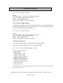
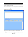
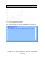
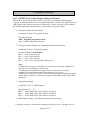
9. Using the Demo Program
ID TECH SecureMag Demo is provided to demonstrate features of the Encrypted MSR.
It supports decrypting the encrypted data and sending command to MSR.
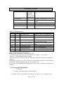
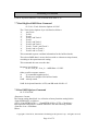
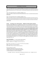
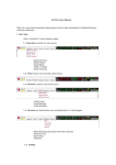
Overview of SecureMag Demo
Screenshot of RS232 Demo Software
The demo software is similar for each interface with exception of interface- specific
settings.
Copyright © 2010-2011, International Technologies & Systems Corp. All rights reserved.
Page 27 of 72
SecureMag User Manual
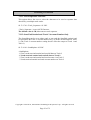
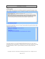
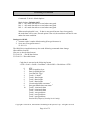
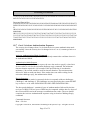
9.1 Manual Command
The demo software allows users to manually input and send commands to the device.
Type the <Command Data> in the field, and the command will be sent
Command will be sent out in the following structure:
<STX> <Command_Data> <ETX> <LRC>
where:
<STX> = 02h, <ETX> = 03h.
<Command_Data> : Please refer to Appendix A for a complete list of commands
<LRC> is a one byte Xor value calculated for the above data block from <STX> to
<ETX>.
eg. 02 53 18 03 4A (Set Default Configuration)
eg. 02 52 22 03 71 (Read Firmware Version)
Press “Send Command”, the input and output would be shown in the lower text box.
Copyright © 2010-2011, International Technologies & Systems Corp. All rights reserved.
Page 28 of 72
SecureMag User Manual
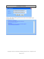
9.2 Decryption
The encrypted data will show in the Manual Command / Encrypted Data textbox after a
card is swiped. By default, the cursor is in Manual Command / Encrypted Data textbox
To get the decrypted data, press the “Decrypt” button and the decrypted card data will be
displayed in the lower box.
The default initial key is 0123456789ABCDEFFEDCBA9876543210. If the reader is
programmed with a user-defined key, load the same key to the demo software by pressing
the “Input Initial Key” button. Type the initial key in the box, and press OK when
finished.
Copyright © 2010-2011, International Technologies & Systems Corp. All rights reserved.
Page 29 of 72
SecureMag User Manual
The Key Value, KSN and Decrypted Data will be shown in the command output/
decrypted data textbox
Copyright © 2010-2011, International Technologies & Systems Corp. All rights reserved.
Page 30 of 72
SecureMag User Manual
9.3 Reader Operations
The demo software can be used to display the card data and send reader commands. To
view the card data on screen, place the cursor in the “manual command/ reader output”
text box and swipe the card. To send a reader command, type the appropriate command
in the text box and press the “Send Command” button.
General Setting
Provide options such as reader default settings, firmware version, beeper options, and
buffered mode options. For USB demo software, there are options to set the reader to
USB KB or USB HID mode.
MSR Security
The security is enabled by selecting TDES or AES. Once the encryption is enabled the
reader cannot be changed back to non-encrypted mode.
Port/ Settings
RS232 interface: select Com port and open/ close port.
USB KB interface: set KB polling interval and select language settings
Help
Provides version information of the demo software.
Copyright © 2010-2011, International Technologies & Systems Corp. All rights reserved.
Page 31 of 72
SecureMag User Manual
10.
Data Format
The USB version of the reader can be operated in two different modes:
- HID ID TECH mode (herein referred to as “HID mode”), Product ID: 2010
- HID with Keyboard Emulation (herein referred to as “KB mode”), Product ID: 2030
When the reader is operated in the HID mode, it behaves like a vendor defined HID
device. A direct communication path can be established between the host application and
the reader without interference from other HID devices.
10.1 Level 1 and level 2 Standard Mode Data Output Format
USB HID Output Format
Card data is only sent to the host on the Interrupt In pipe using an Input Report. The reader
will send only one Input Report per card swipe. If the host requests data from the reader
when no data is available, the reader will send a NAK to the host to indicate that it has
nothing to send.
Copyright © 2010-2011, International Technologies & Systems Corp. All rights reserved.
Page 32 of 72
SecureMag User Manual
10.1.1.
USB HID Data Format
Other Mode Reader Data Structure
Offset
Usage Name
.
0
T1 decode status
1
T2 decode status
2
T3 decode status
3
T1 data length
4
T2 data length
5
T3 data length
6
Card encode type
7-116
T1 data
117-226
T2 data
227-336
T3 data
Notes:
T1, T2 or T3 decode status: 0 for no error, 1 for error
T1, T2 or T3 Data Length: Each byte value indicates how many bytes of
decoded card data are in the track data field. This value will be zero if
there was no data on the track or if there was an error decoding the track.
Card Encode Type:
Value Encode Type Description
0
ISO/ABA
ISO/ABA encode format
1
AAMVA
AAMVA encode format
3
Other
The card has a non-standard format. For
example, ISO/ABA track 1 format on track 2
4
Raw
The card data is sent in Raw encrypted
format. All tracks are encrypted and no mask data is sent
T1, T2 or T3 data: The length of each track data field is fixed at 110 bytes, but
the length of valid data in each field is determined by the track data length field
that corresponds to the track number. The track data includes all data string
starting with the start sentinel and ending with the end sentinel.
ID TECH Reader Data Structure
Offset
Usage Name
0
T1 decode status
1
T2 decode status
2
T3 decode status
3
T1 data length
4
T2 data length
5
T3 data length
6
Card encode type
.
Copyright © 2010-2011, International Technologies & Systems Corp. All rights reserved.
Page 33 of 72
SecureMag User Manual
7,8
Total Output Length
9-512
Output Data
In this approach, the reader will keep all of the ID TECH data editing and
other features like preamble, postamble, etc. The output data is always 512
bytes; the "Total Output Length" field indicates the valid data length in the
output data
10.1.2.
Descriptor Tables
Device Descriptor:
Field
Length
Des type
bcd USB
Device Class
Sub Class
Device Protocol
Max Packet Size
VID
PID
BCD Device Release
i-Manufacture
i-Product
i-Serial-Number
# Configuration
Value
12
01
00 02
00
00
00
08
0A CD
20 10
20 20
20 30
00 01
01
02
00
01
Description
USB 2.0
Unused
Unused
Unused
HID ID TECH Structure
HID Other Structure
HID Keyboard
Configuration Descriptor:
Field
Length
Des type
Total Length
No. Interface
Configuration Value
iConfiguration
Attributes
Value
09
02
22 00
01
01
00
80
Description
Bus power, no remove wakeup
Copyright © 2010-2011, International Technologies & Systems Corp. All rights reserved.
Page 34 of 72
SecureMag User Manual
Power
32
100 mA
Value
09
04
00
00
01
03
01
01
00
Description
Value
09
21
11 01
00
01
22
37 00
3D 00
52 00
Description
Interface Descriptor:
Field
Length
Des type
Interface No.
Alternator Setting
# EP
Interface Class
Sub Class
Interface Protocol
iInterface
HID
HID Descriptor:
Field
Length
Des type
bcdHID
Control Code
numDescriptors
DescriptorType
Descriptor Length
HID
Number of Class Descriptors to follow
Report Descriptor
HID ID TECH format
HID Other format
HID Keyboard format
End Pointer Descriptor:
Field
Length
Des Type
EP Addr
Attributes
MaxPacketSize
bInterval
Value
07
05
83
03
40 00
01
Description
End Point
EP3 – In
Interrupt
Report Descriptor: (USB-HID Setting)
Value
Description
Copyright © 2010-2011, International Technologies & Systems Corp. All rights reserved.
Page 35 of 72
SecureMag User Manual
06 00
FF
09 01
A1 01
15 00
26 FF
00
75 08
09 20
09 21
09 22
09 28
09 29
09 2A
09 38
95 07
81 02
09 30
95 02
82 02
01
09 31
96 10
02
82 02
01
09 20
95 08
B2 02
01
C0
Usage Page (MSR)
Usage(Decoding Reader Device)
Collection (Application)
Logical Minimum
Logical Maximum
Report Size
Usage (Tk1 Decode Status)
Usage (Tk2 Decode Status)
Usage (Tk3 Decode Status)
Usage (Tk1 Data Length)
Usage (Tk2 Data Length)
Usage (Tk3 Data Length)
Usage (Card Encode Type)
Report Count
Input (Data,Var,Abs,Bit Field)
Usage (Total Sending Length)
Report Count (2)
Input (Data, Var, Abs, Bit Field)
Usage (Output Data)
Report Count (512 + 16 )
Input (Data, Var, Abs, Bit Field)
Usage (Command Message)
Report Count
Feature (Data,Var, Abs, Buffered Bytes)
End Collection
Report Descriptor: (USB KB Interface)
Value
05 01
09 06
A1 01
05 07
19 E0
29 E7
15 00
25 01
Description
Usage Page (Generic Desktop)
Usage(Keyboard)
Collection (Application)
Usage Page (Key Codes)
Usage Minimum
Usage Maximum
Logical Minimum
Logical Maximum
Copyright © 2010-2011, International Technologies & Systems Corp. All rights reserved.
Page 36 of 72
SecureMag User Manual
75 01
95 08
81 02
95 01
75 08
81 01
95 05
75 01
05 08
19 01
29 05
91 02
95 01
75 03
91 01
95 06
75 08
15 00
25 66
05 07
19 00
29 66
81 00
06 2D
FF
95 01
26 FF
00
15 01
75 08
09 20
95 08
B2 02
01
C0
Report Size
Report Count
Input (Data,Variable,Absolute)
Report Count (1)
Report Size
Input Constant
Report Count
Report Size
Usage Page (LED)
Usage Minimum
Usage maximum
Output(Data Variable Absolute)
Report Count
Report Size
Output (Constant)
Report Count
Report Size
Logical Minimum
Logical Maximum (102)
Usage Page (key Code)
Usage Minimum
Usage Maximum (102)
Input(Data, Array)
Usage Page (ID TECH)
Report Count
Logical maximum (255)
Logical Minimum
Report Size (8)
Usage (Setup data byte)
Report Count (8)
Feature (Data Var, Abs)
End Collection
10.2 Level 1 and level 2 POS Mode Data Output Format
In POS mode use the special envelope to send out card data, envelope is in the
following format:
Copyright © 2010-2011, International Technologies & Systems Corp. All rights reserved.
Page 37 of 72
SecureMag User Manual
[Right Shift, Left Shift, Right Ctrl, Left Ctrl,] Read Error, Track x ID; Track x
Error; Track x Data Length; Track x Data; Card Track x LEC code; Track x
data LRC.
Reader will send out card data in Alt mode if its ASCII code less than H’20’.
Byte NO.
0
1
2
3
4
5
6
7
8
9
10
10 + Track len -1
10 + Track len
10 + Track len +1
10 + Track len + 2
….
Name
Right Shift
Left Shift
Right Ctrl
Left Ctrl
Read Error 1
Read Error 2
Track x ID
Track x Error
Track x Length 1
Track x Length 2
Track Data (no extra
Track ID for raw data)
…
Card Track x LRC
Track x LRC
0x0D
Track x ID
Repeat Track
The data format is independent with MSR setting. No Track x data if track x
sampling data does not exist.
OPOS header:
Only HID KB interface has [Right Shift, Left Shift, Right Ctrl, Left Ctrl] under
POS mode.
Read Error:
Read Error 1 byte bits:
MB
LB
0
B6
B5
B4
B3
B2
B1
B0
B0
1: Track 1 sampling data exists (0: Track 1 sampling data does not exist)
B1
1: Track 2 sampling data exists (0: Track 2 sampling data does not exist)
B2
1: Track 3 sampling data exists (0: Track 3 sampling data does not exist)
B3
1: Track 1 decode success (0: Track 1 decode fail)
B4
1: Track 2 decode success (0: Track 2 decode fail)
B5
1: Track 3 decode success (0: Track 3 decode fail)
B6
0: if b0 to b5 are all 1, otherwise 1 (make it printable)
Copyright © 2010-2011, International Technologies & Systems Corp. All rights reserved.
Page 38 of 72
SecureMag User Manual
Read Error byte 2:
MB
0
1
LB
B12
B11
B10
B9
B8
B7
B7
1: Track 4 sampling data exists (0: Track 4 sampling data does not exist)
B8
1: Track 4 JIS II decode success (0: Track4 JIS II decode fail)
B9, B10, B11
000: ISO Card (7, 5) or (7, 5, 5) encoding
001: Old CADL Card (6, 5, 6) encoding (no longer included)
010: AAMVA Card (7, 5, 7) encoding
011: JIS I Card (8, 5, 8) encoding
100: JIS II card (8) or ISO+JIS II
110: OPOS Raw Data Output
111: JIS I + JIS II
B12
Reserved for future use
Decode flag will set to 1 (B3, B4 and B5 all set to 1) in OPOS raw data mode.
Track ID
Track ID is a byte of ID, it will be '1', '2' and '3' for track 1, 2 and 3; it is not
accurate to use start sentinel to identify track.
Track x Error
Track x error is a byte of flags, it will be in format of: 0 0 1 b4, b3, b2 b1 b0
b0
1: Start sentinel error (0: Not start sentinel error)
b1
1: End sentinel error (0: Not end sentinel error)
b2
1: Parity error (0: Not parity error)
b3
1: LRC error (0: Not LRC error)
b4
1: Other error (0: Not other error)
Track x Error is set to 0x20 in OPOS raw data mode.
Track Length
Assume actual "Track x Data Length" is hex code xy; the Track x data length for
OPOS mode output will be hex code 3x, 3y.
Track x data length does not include the byte of "Track x data LRC", it is <30>
<30> in case of read error on track x.
Track Data
“Card Track x LRC code” is track x card data.
Track x LRC
“Track x data LRC” is a LRC to check track x data communication; XOR all
characters start from "Track x ID" to “Track x data LRC” should be 0.
Copyright © 2010-2011, International Technologies & Systems Corp. All rights reserved.
Page 39 of 72
SecureMag User Manual
10.3 DUKPT Level 3 Data Output Enhanced Format
This mode is used when all tracks must be encrypted, or encrypted OPOS support is
required, or when the tracks must be encrypted separately or when cards other than type 0
(ABA bank cards) must be encrypted or when track 3 must be encrypted. This format is
the standard encryption format, but not yet the default encryption format.
1. Encryption Output Format Setting:
Command: 53 85 01 <Encryption Format>
Encryption Format:
‘00h’: Original Encryption Format
‘01h’: Enhanced Encryption Format
2. Encryption Option Setting: (for enhanced encryption format only)
Command: 53 84 01 <Encryption Option>
Encryption Option: (default 08h)
bit0: 1 – track 1 force encrypt
bit1: 1 – track 2 force encrypt
bit2: 1 – track 3 force encrypt
bit3: 1 – track 3 force encrypt when card type is 0
Note:
1) When force encrypt is set, this track will always be encrypted, regardless of
card type. No clear/mask text will be sent.
2) If and only if in enhanced encryption format, each track is encrypted
separately. Encrypted data length will round up to 8 or 16 bytes.
3) When force encrypt is not set, the data will be encrypted in original encryption
format, that is, only track 1 and track 2 of type 0 cards (ABA bank cards) will be
encrypted.
3. Hash Option Setting:
Command: 53 5C 01 <Hash Option>
Hash Option: (‘0’ – ‘7’)
Bit0: 1 – track1 hash will be sent if data is encrypted
Bit1: 1 – track2 hash will be sent if data is encrypted
Bit2: 1 – track3 hash will be sent if data is encrypted
4. Mask Option Setting: (for enhanced encryption format only)
Copyright © 2010-2011, International Technologies & Systems Corp. All rights reserved.
Page 40 of 72
SecureMag User Manual
Command: 53 86 01 <Mask Option>
Mask Option: (Default: 0x07)
bit0: 1 – tk1 mask data allow to send when encrypted
bit1: 1 – tk2 mask data allow to send when encrypted
bit2: 1 – tk3 mask data allow to send when encrypted
When mask option bit is set – if data is encrypted (but not forced encrypted),
the mask data will be sent; If mask option is not set, the mask data will not be sent
under the same condition.
Settings for OPOS:
1. Assume reader is under default setting (Encrypt Structure 0)
2. Set to new Encrypt Structure 1:
53 85 01 31
The OPOS driver/application may also send following command when change
(Decode/Raw format)
(Set raw or decode data format)
53 1D 01 30 // RAW data format
53 1D 01 31 // Decoded format
Card data is sent out in the following format
<STX><LenL><LenH><Card Data><CheckLRC><CheckSum><ETX>
0
1
2
3
4
5
6
7
8
9
10
STX
Data Length low byte
Data Length high byte
Card Encode Type1
Track 1-3 Status2
Track 1 data length
Track 2 data length
Track 3 data length
Clear/masked data sent status 3
Encrypted/Hash data sent status 4
Track 1 clear/mask data
Track 2 clear/mask data
Track 3 clear/mask data
Track 1 encrypted data
Track 2 encrypted data
Track 3 encrypted data
Session ID (8 bytes) (Security level 4 only)
Copyright © 2010-2011, International Technologies & Systems Corp. All rights reserved.
Page 41 of 72
SecureMag User Manual
Track 1 hashed (20 bytes each) (if encrypted and hash track 1
allowed)
Track 2 hashed (20 bytes each) (if encrypted and hash track 2
allowed)
Track 3 hashed (20 bytes each) (if encrypted and hash track 3
allowed)
KSN (10 bytes)
CheckLRC
CheckSum
ETX
Where <STX> = 02h, <ETX> = 03h
Note 1 : Card Encode Type
Card Type will be 8x for enhanced encryption format and 0x for original
encryption format
Value
00h / 80h
01h / 81h
03h / 83h
04h / 84h
Encode Type Description
ISO/ABA format
AAMVA format
Other
Raw; un-decoded format
For Type 04 or 84 Raw data format, all tracks are encrypted and no mask
data is sent. No track indicator ‘01’, ‘02’ or ‘03’ in front of each track.
Track indicator ‘01’,’02’ and ‘03’ will still exist for non-encrypted mode.
Note 2: Track 1-3 status byte
Field 4:
Bit 0: 1— track 1 decoded data present
Bit 1: 1— track 2 decoded data present
Bit 2: 1— track 3 decoded data present
Bit 3: 1— track 1 sampling data present
Bit 4: 1— track 2 sampling data present
Bit 5: 1— track 3 sampling data present
Bit 6, 7 — Reserved for future use
Note 3: Clear/mask data sent status
Field 8 (Clear/mask data sent status) and field 9 (Encrypted/Hash data sent
status) will only be sent out in enhanced encryption format.
Field 8: Clear/masked data sent status byte:
Copyright © 2010-2011, International Technologies & Systems Corp. All rights reserved.
Page 42 of 72
SecureMag User Manual
Bit 0: 1 —track 1 clear/mask data present
Bit 1: 1— track 2 clear/mask data present
Bit 2: 1— track 3 clear/mask data present
Bit 3: 0— reserved for future use
Bit 4: 0— reserved for future use
Bit 5: 0— reserved for future use
Note 4: Encrypted/Hash data sent status
Field 9: Encrypted data sent status
Bit 0: 1— track 1 encrypted data present
Bit 1: 1— track 2 encrypted data present
Bit 2: 1— track 3 encrypted data present
Bit 3: 1— track 1 hash data present
Bit 4: 1— track 2 hash data present
Bit 5: 1— track 3 hash data present
Bit 6: 1—session ID present
Bit 7: 1—KSN present
10.4 DUKPT Level 3 Data Output Original Format
For ISO cards, both masked clear and encrypted data are sent, no clear data will
be sent.
For other cards, only clear data is sent.
A card swipe returns the following data:
Card data is sent out in format of
<STX><LenL><LenH><Card Data><CheckLRC><CheckSum><ETX>
<STX> = 02h, <ETX> = 03h
<LenL><LenH> is a two byte length of <Card Data>.
<CheckLRC> is a one byte Exclusive-OR sum calculated for all <Card Data>.
<CheckSum> is a one byte Sum value calculated for all <Card data>.
<Card Data> card data format is shown below.
ISO/ABA Data Output Format:
card encoding type
track status
3,4,5:T1,2,3 sampling)
track 1 unencrypted length
track 2 unencrypted length
track 3 unencrypted length
track 1 masked
(0: ISO/ABA, 4: for Raw Mode)
(bit 0,1,2:T1,2,3 decode, bit
(1 byte, 0 for no track1 data)
(1 byte, 0 for no track2 data)
(1 byte, 0 for no track3 data)
(Omitted if in Raw mode)
Copyright © 2010-2011, International Technologies & Systems Corp. All rights reserved.
Page 43 of 72
SecureMag User Manual
track 2 masked
track 3 data
track 1 encrypted
track 2 encrypted
track 3 encrypted
track 1 hashed
track 2 hashed
DUKPT serial number
(Omitted if in Raw mode)
(Omitted if in Raw mode)
(AES/TDES encrypted data)
(AES/TDES encrypted data)
(Only used in Raw mode)
(20 bytes SHA1-Xor)
(20 bytes SHA1-Xor)
(10 bytes)
Non ISO/ABA Data Output Format
card encoding type
track status
3,4,5:T1,2,3 sampling)
track 1 length
track 2 length
track 3 length
track 1 data
track 2 data
track 3 data
(1: AAMVA, 3: Others)
(bit 0,1,2:T1,2,3 decode, bit
(1 byte, 0 for no track1 data)
(1 byte, 0 for no track2 data)
(1 byte, 0 for no track3 data)
10.5 DUKPT Level 4 Data Output Original Format
For ISO card, both clear and encrypted data are sent. For other card, only clear
data are sent.
A card swipe returns the following data:
Card data is sent out in format of
<STX><LenL><LenH><Card Data><CheckLRC><CheckSum><ETX>
<STX> = 02h, <ETX> = 03h
<LenL><LenH> is a two byte length of <Card Data>.
<CheckLRC> is a one byte Exclusive-OR sum calculated for all <Card Data>.
<CheckSum> is a one byte Sum value calculated for all <Card data>.
<Card Data> format is
ISO/ABA Data Output Format:
card encoding type
track status
3,4,5:T1,2,3 sampling)
track 1 unencrypted length
track 2 unencrypted length
track 3 unencrypted length
if card encoding type high bit set
■ mask and clear sent track status
(0: ISO/ABA, 4: for Raw Mode)
(bit 0,1,2:T1,2,3 decode, bit
(1 byte, 0 for no track1 data)
(1 byte, 0 for no track2 data)
(1 byte, 0 for no track3 data)
Copyright © 2010-2011, International Technologies & Systems Corp. All rights reserved.
Page 44 of 72
SecureMag User Manual
encrypt and hash sent track status
In this mode tracks are encrypted separately rather than as a group
track 1 masked
(Omitted if in Raw mode)
track 2 masked
(Omitted if in Raw mode)
track 3 data
(Omitted if in Raw mode)
track 1 encrypted
(AES/TDES encrypted data)
track 2 encrypted
(AES/TDES encrypted data)
sessionID encrypted
(AES/TDES encrypted data)
track 1 hashed
(20 bytes SHA1-Xor)
track 2 hashed
(20 bytes SHA1-Xor)
track 3 hashed (optional)
(20 bytes SHA1-Xor)
DUKPT serial number
(10 bytes)
■
Non ISO/ABA Data Output Format:
card encoding type
track status
3,4,5:T1,2,3 sampling)
track 1 length
track 2 length
track 3 length
track 1 data
track 2 data
track 3 data
(1: AAMVA, 3: Others)
(bit 0,1,2:T1,2,3 decode, bit
(1 byte, 0 for no track1 data)
(1 byte, 0 for no track2 data)
(1 byte, 0 for no track3 data)
Except for USBKB and PS2 interfaces, track formatting (preamble, prefix,
separator, etc.) is not supported in a reader set to send encrypted track data. The
track data is always sent in the same format that is with no special formatting so
that the program doing the decoding can know where is data field is located. For
USBKB and PS2 interfaces, preamble and postamble will be available in the
encrypted track data
Offset to the fields can be determined by adding the field lengths using the track
data for the track field lengths. Fields are packed in the next available location.
T1, T2 or T3 Data Length: Each byte value indicates how many bytes of
decoded card data are in the track data field. This value will be zero if there was
no data on the track or if there was an error decoding the track.
The encrypted section is padded with zeros to the block size of the encryption
type, 8 bytes for TDES and 16 bytes for AES.
The hashed data may optionally be omitted, and also track 3 may be hashed and
included.
Copyright © 2010-2011, International Technologies & Systems Corp. All rights reserved.
Page 45 of 72
SecureMag User Manual
Description:
Track 1 and Track 2 unencrypted Length
This one-byte value is the length of the original Track data. It indicates the
number of bytes in the Track masked data field. It should be used to separate
Track 1 and Track 2 data after decrypting Track encrypted data field.
Track 3 unencrypted Length
This one-byte value indicates the number of bytes in Track 3 masked data field.
Track 1 and Track 2 masked
Track data masked with the MaskCharID (default is ‘*’). The first PrePANID (up
to 6 for BIN, default is 4) and last PostPANID (up to 4, default is 4) characters
can be in the clear (unencrypted). The expiration date is masked by default but
can be optionally displayed.
Track 1 and Track 2 encrypted
This field is the encrypted Track data, using either TDES-CBC or AES-CBC with
initial vector of 0. If the original data is not a multiple of 8 bytes for TDES or a
multiple of 16 bytes for AES, the reader right pads the data with 0.
The key management scheme is DUKPT and the key used for encrypting data is
called the Data Key. Data Key is generated by first taking the DUKPT Derived
Key exclusive or’ed with 0000000000FF0000 0000000000FF0000 to get the
resulting intermediate variant key. The left side of the intermediate variant key is
then TDES encrypted with the entire 16-byte variant as the key. After the same
steps are preformed for the right side of the key, combine the two key parts to
create the Data Key.
How to get Encrypted Data Length
Track 1 and Track 2 data are encrypted as a single block. In order to get the
number of bytes for encrypted data field, we need to get Track 1 and Track 2
unencrypted length first. The field length is always a multiple of 8 bytes for
TDES or multiple of 16 bytes for AES. This value will be zero if there was no
data on both tracks or if there was an error decoding both tracks. Once the
encrypted data is decrypted, all padding 0 need to be removed. The number of
bytes of decoded track 1 data is indicated by track 1 unencrypted length field. The
remaining bytes are track 2 data, the length of which is indicated by track 2
unencrypted length filed.
Track 1, 2 and 3 hashed
SecureMag reader uses SHA-1 to generate hashed data for both track 1, track 2
and track 3 unencrypted data. It is 20 bytes long for each track. This is provided
Copyright © 2010-2011, International Technologies & Systems Corp. All rights reserved.
Page 46 of 72
SecureMag User Manual
with two purposes in mind: One is for the host to ensure data integrity by
comparing this field with a SHA-1 hash of the decrypted Track data, prevent
unexpected noise in data transmission. The other purpose is to enable the host to
store a token of card data for future use without keeping the sensitive card holder
data. This token may be used for comparison with the stored hash data to
determine if they are from the same card.
Some Additional notes: (4/28/2011)
1. “Decode status” bits in “track status” byte is set as: 0 for no error (either
decode success or no sampling data), or to 1 for error (has sampling
data but fail to decode).
2. Please be aware that track status byte in secured output is different from
track status bytes in OPOS head (called read error1 and read error2).
OPOS header will only be used in OPOS mode security level 1 and
level 2 and secure output only used in level 3 or level 4.
3. For USB HID Secure Output, the output format is same as Secure
Output structure. No HID header is added. But the total length is the
HID standard (537 bytes). Unused bytes will be filled with 0x00. This
applied to secure Level 3 and Level 4 output, whether or not the data is
encrypted.
4. Examples for field 8 (Clear/mask data sent status) and field 9
(Encrypted/Hash data sent status)
These two bytes are omitted in original structure. In the enhanced
encrypt structure, these two byte are used to indicate the presence of
each track’s Clear or Masked data, Encrypted data and hash data.
Example :
field 8 = 0x03 (00000011)
field 9 = 0xBF (10111111)
T1: Mask data present; Encrypted data present; Hash present
T2: Mask data present; Encrypted data present; Hash present
T3: No Mask data; Encrypted data present; Hash present
KSN: present
Session ID: not present
Additional Settings
Send LRC in secured mode (6F)
53 6F 01 31 // to send LRC in secure mode (Default)
53 6F 01 30 // Remove LRC in secure mode
Display Expiration Data (50)
53 50 01 30 // Do not display Expiration Date (Exp date Masked)
(Default)
53 50 01 31 // Display Expiration Data
Reader Serial Number (4E)
Copyright © 2010-2011, International Technologies & Systems Corp. All rights reserved.
Page 47 of 72
SecureMag User Manual
The serial number will be set to the same as S/N in unit’s label. The length
is 8 to 10 characters. User can read out the S/N with 52 4E command.
10.6 Decryption Example
Key for all examples is
0123456789ABCDEFFEDCBA9876543210
10.6.1.
Security Level 3 Decryption - Original Encryption Format
Decryption of a three track ABA card with the original encryption format.
SecureMag Reader with default settings
Original encryption format can be recognized because the high bit of the fourth byte
underlined (00) is 0.
027D01003F48236B252A343236362A2A2A2A2A2A2A2A393939395E42555348204A
522F47454F52474520572E4D525E2A2A2A2A2A2A2A2A2A2A2A2A2A2A2A2A2A2
A2A2A2A2A2A2A2A2A2A2A2A2A2A3F2A3B343236362A2A2A2A2A2A2A2A3939
39393D2A2A2A2A2A2A2A2A2A2A2A2A2A2A2A3F2A3B3333333333333333333337
363736373630373037303737363736373633333333333333333333373637363736303730
373037373637363736333333333333333333333736373637363037303730373736373637
3633333333333333333333373637363736303730373F32863E9E3DA28E455B28F7736
B77E47A64EDDA3BF03A06E44F31D1818C0BCD7A353FB1AD70EFD30FFC3DA08
A4FBC9372E57E8B40848BAEAA3FE724B3550E2F4B223E6BF264BEAE9E39142B6
48CDB51FB8DAF8EA5B63913D29419B67582FCCCE9B372660F03668CC453216D9
449C6B67EF33418AC88F65E1DB7ED4D10973F99DFC8463FF6DF113B6226C4898A
9D355057ECAF11A5598F02CA3162994901190000000001399F03
STX, Length (LSB, MSB), card type, track status, length track 1, length track 2, length
track 3
02 7D01 00 3F 48 23 6B
The above broken down and interpreted
02—STX character
7D—low byte of total length
01—high byte of total length
00—card type byte (interpretation old format ABA card)
3F—3 tracks of data all good
48—length of track 1
23—length of track 2
Copyright © 2010-2011, International Technologies & Systems Corp. All rights reserved.
Page 48 of 72
SecureMag User Manual
6B—length of track 3
Track 1 data masked (length 0x48)
252A343236362A2A2A2A2A2A2A2A393939395E42555348204A522F47454F5247452
0572E4D525E2A2A2A2A2A2A2A2A2A2A2A2A2A2A2A2A2A2A2A2A2A2A2A2A2
A2A2A2A2A2A2A3F2A
Track 2 data in hex masked (length 0x23)
3B343236362A2A2A2A2A2A2A2A393939393D2A2A2A2A2A2A2A2A2A2A2A2A2
A2A2A3F2A
Track 3 data unencrypted (length 0x6B)
3B333333333333333333333736373637363037303730373736373637363333333333333
333333337363736373630373037303737363736373633333333333333333333373637363
73630373037303737363736373633333333333333333333373637363736303730373F32
Track 1 & 2 encrypted length 0x48+0x23 rounded up to 8 bytes =0x6B -> 0x70 (112
decimal)
863E9E3DA28E455B28F7736B77E47A64EDDA3BF03A06E44F31D1818C0BCD7A3
5
3FB1AD70EFD30FFC3DA08A4FBC9372E57E8B40848BAEAA3FE724B3550E2F4B2
2
3E6BF264BEAE9E39142B648CDB51FB8DAF8EA5B63913D29419B67582FCCCE9B
3
72660F03668CC453216D9449C6B67EF3
Track 1 hashed
3418AC88F65E1DB7ED4D10973F99DFC8463FF6DF
Track 2 hashed
113B6226C4898A9D355057ECAF11A5598F02CA31
KSN
62994901190000000001
LRC, checksum and ETX
39 9F 03
Masked Data:
Track 1 data masked in ASCII:
%*4266********9999^BUSH JR/GEORGE
W.MR^*******************************?*
Track 2 data masked in ASCII:
Copyright © 2010-2011, International Technologies & Systems Corp. All rights reserved.
Page 49 of 72
SecureMag User Manual
;4266********9999=***************?*
Track 3 data unencrypted in ASCII:
;33333333337676760707077676763333333333767676070707767676333333333376767
607070776767633333333337676760707?2
Key Value: F8 2A 7A 0D 7C 67 46 F1 96 18 9A FB 54 2C 65 A3
KSN: 62 99 49 01 19 00 00 00 00 01
Decrypted Data in ASCII:
%B4266841088889999^BUSH JR/GEORGE
W.MR^0809101100001100000000046000000?!;4266841088889999=080910110000046
?0
;33333333337676760707077676763333333333767676070707767676333333333376767
607070776767633333333337676760707?2
Decrypted Data in Hex:
2542343236363834313038383838393939395E42555348204A522F47454F52474520572
E4D525E303830393130313130303030313130303030303030303034363030303030303F
213B343236363834313038383838393939393D3038303931303131303030303034363F3
00000000000
10.6.2.
Security Level 4 Decryption - Original Encryption Format
028501003F48236B252A343236362A2A2A2A2A2A2A2A393939395E42555348204A
522F47454F52474520572E4D525E2A2A2A2A2A2A2A2A2A2A2A2A2A2A2A2A2A2
A2A2A2A2A2A2A2A2A2A2A2A2A2A3F2A3B343236362A2A2A2A2A2A2A2A3939
39393D2A2A2A2A2A2A2A2A2A2A2A2A2A2A2A3F2A3B3333333333333333333337
363736373630373037303737363736373633333333333333333333373637363736303730
373037373637363736333333333333333333333736373637363037303730373736373637
3633333333333333333333373637363736303730373F32ED9DB728814F150D177F769
B0441C52B2B1994C83D058F1DDA5DAA6753CF0F61BB7690C7E8A276D3D60651
3D1F8B79423C70594A0849CBB4C7B5A8DAC2B1A21B11F1C47EF4F12AC07D59A
79E9369372D3F906A7F6C6D2B9076BCF05B334441FAEC8B4EFBEB9DD20EBF97
B29D910C415FCEA8DA8FEB9775343418AC88F65E1DB7ED4D10973F99DFC8463F
F6DF113B6226C4898A9D355057ECAF11A5598F02CA31629949011900000000044B
6F03
Masked Data:
Track 1: %*4266********9999^BUSH JR/GEORGE
W.MR^*******************************?*
Track 2: ;4266********9999=***************?*
Track 3:
;33333333337676760707077676763333333333767676070707767676333333333376767
607070776767633333333337676760707?2
Copyright © 2010-2011, International Technologies & Systems Corp. All rights reserved.
Page 50 of 72
SecureMag User Manual
Key Value: 8A 92 F6 74 00 BF 25 2E 57 9A A9 01 FF 27 48 41
KSN: 62 99 49 01 19 00 00 00 00 04
Session ID: AA AA AA AA AA AA AA AA
Decrypted Data in ASCII:
%B4266841088889999^BUSH JR/GEORGE
W.MR^0809101100001100000000046000000?!;4266841088889999=080910110000046
?0
;33333333337676760707077676763333333333767676070707767676333333333376767
607070776767633333333337676760707?2
Decrypted Data in Hex:
2542343236363834313038383838393939395E42555348204A522F47454F52474520572
E4D525E303830393130313130303030313130303030303030303034363030303030303F
213B343236363834313038383838393939393D3038303931303131303030303034363F3
0AAAAAAAAAAAAAAAA0000000000
10.6.3.
Security Level 3 Decryption - Enhanced Encryption Format
Example of decryption of a three track ABA card with the enhanced encryption format.
SecureMag Reader with default settings except enhanced encryption structure format.
Enhanced encryption Format (this can be recognized because the high bit of the fourth
byte underlined (80) is 1.
029801803F48236B03BF252A343236362A2A2A2A2A2A2A2A393939395E42555348
204A522F47454F52474520572E4D525E2A2A2A2A2A2A2A2A2A2A2A2A2A2A2A2
A2A2A2A2A2A2A2A2A2A2A2A2A2A2A2A3F2A3B343236362A2A2A2A2A2A2A2
A393939393D2A2A2A2A2A2A2A2A2A2A2A2A2A2A2A3F2ADA7F2A52BD3F6DD
8B96C50FC39C7E6AF22F06ED1F033BE0FB23D6BD33DC5A1F808512F7AE18D47
A60CC3F4559B1B093563BE7E07459072ABF8FAAB5338C6CC8815FF87797AE3A7
BEAB3B10A3FBC230FBFB941FAC9E82649981AE79F2632156E775A06AEDAFAF6
F0A184318C5209E55AD44A9CCF6A78AC240F791B63284E15B4019102BA6C50581
4B585816CA3C2D2F42A99B1B9773EF1B116E005B7CD8681860D174E6AD316A0E
CDBC687115FC89360AEE7E430140A7B791589CCAADB6D6872B78433C3A25DA9
DDAE83F12FEFAB530CE405B701131D2FBAAD970248A456000933418AC88F65E1
DB7ED4D10973F99DFC8463FF6DF113B6226C4898A9D355057ECAF11A5598F02C
A31688861C157C1CE2E0F72CE0F3BB598A614EAABB16299490119000000000206E
203
STX, Length(LSB, MSB), card type, track status, length track 1, length track 2, length
track 3
02 9801 80 3F 48-23-6B 03BF
Copyright © 2010-2011, International Technologies & Systems Corp. All rights reserved.
Page 51 of 72
SecureMag User Manual
The above broken down and interpreted
02—STX character
98—low byte of total length
01—high byte of total length
80—card type byte (interpretation new format ABA card)
3F—3 tracks of data all good
48—length of track 1
23—length of track 2
6B—length of track 3
03—tracks 1 and 2 have masked/clear data
BF—bit 7=1—KSN included
Bit 6=0—no Session ID included so not level 4 encryption
Bit 5=1—track 3 hash data present
Bit 4=1—track 2 hash data present
Bit 3-1—track 1 hash data present
Bit 2=1—track 3 encrypted data present
Bit 1=1—track 2 encrypted data present
Bit 0=1—track 1 encrypted data present
Track 1 data masked (length 0x48)
252A343236362A2A2A2A2A2A2A2A393939395E42555348204A522F47454F5247452
0572E4D525E2A2A2A2A2A2A2A2A2A2A2A2A2A2A2A2A2A2A2A2A2A2A2A2A2
A2A2A2A2A2A2A3F2A
Track 1 masked data in ASCII
%*4266********9999^BUSH JR/GEORGE
W.MR^*******************************?*
Track 2 data in hex masked (length 0x23)
3B343236362A2A2A2A2A2A2A2A393939393D2A2A2A2A2A2A2A2A2A2A2A2A2
A2A2A3F2A
Track2 masked data in ASCII
;4266********9999=***************?*
In this example there is no Track 3 data either clear or masked (encrypted and hashed
data is below)
Track 1 encrypted length 0x48 rounded up to 8 bytes = 0x48 (72 decimal)
DA7F2A52BD3F6DD8B96C50FC39C7E6AF22F06ED1F033BE0FB23D6BD33DC5A1
F8
08512F7AE18D47A60CC3F4559B1B093563BE7E07459072ABF8FAAB5338C6CC88
15FF87797AE3A7BE
Copyright © 2010-2011, International Technologies & Systems Corp. All rights reserved.
Page 52 of 72
SecureMag User Manual
Track 2 encrypted length 0x32 rounded up to 8 bytes =0x38 (56 decimal)
AB3B10A3FBC230FBFB941FAC9E82649981AE79F2632156E775A06AEDAFAF6F0
A
184318C5209E55AD
Track 3 encrypted length 0x6B rounded up to 8 bytes =0x70 (64 decimal)
44A9CCF6A78AC240F791B63284E15B4019102BA6C505814B585816CA3C2D2F42
A99B1B9773EF1B116E005B7CD8681860D174E6AD316A0ECDBC687115FC89360A
EE7E430140A7B791589CCAADB6D6872B78433C3A25DA9DDAE83F12FEFAB530
CE
405B701131D2FBAAD970248A45600093
Track 1 data hashed length 20 bytes
3418AC88F65E1DB7ED4D10973F99DFC8463FF6DF
Track 2 data hashed length 20 bytes
113B6226C4898A9D355057ECAF11A5598F02CA31
Track 3 data hashed length 20 bytes
688861C157C1CE2E0F72CE0F3BB598A614EAABB1
KSN length 10 bytes
62994901190000000002
LCR, check sum and ETX
06E203
Clear/Masked Data in ASCII:
Track 1: %*4266********9999^BUSH JR/GEORGE
W.MR^*******************************?*
Track 2: ;4266********9999=***************?*
Key Value: 1A 99 4C 3E 09 D9 AC EF 3E A9 BD 43 81 EF A3 34
KSN: 62 99 49 01 19 00 00 00 00 02
Decrypted Data:
Track 1 decrypted
%B4266841088889999^BUSH JR/GEORGE
W.MR^0809101100001100000000046000000?!
Track 2 decrypted
;4266841088889999=080910110000046?0
Track 3 decrypted
;33333333337676760707077676763333333333767676070707767676333333333376767
607070776767633333333337676760707?2
Copyright © 2010-2011, International Technologies & Systems Corp. All rights reserved.
Page 53 of 72
SecureMag User Manual
Track 1 decrypted data in hex including padding zeros (but there are no pad bytes here)
2542343236363834313038383838393939395E42555348204A522F47454F52474520572
E4D525E303830393130313130303030313130303030303030303034363030303030303F
21
Track 2 decrypted data in hex including padding zeros
3B343236363834313038383838393939393D3038303931303131303030303034363F300
000000000
Track 3 decrypted data in hex including padding zeros
3B333333333333333333333736373637363037303730373736373637363333333333333
333333337363736373630373037303737363736373633333333333333333333373637363
73630373037303737363736373633333333333333333333373637363736303730373F32
0000000000
10.6.4.
Security Level 4 Decryption – Enhanced Encryption Format
02A001803F48236B03FF252A343236362A2A2A2A2A2A2A2A393939395E42555348
204A522F47454F52474520572E4D525E2A2A2A2A2A2A2A2A2A2A2A2A2A2A2A2
A2A2A2A2A2A2A2A2A2A2A2A2A2A2A2A3F2A3B343236362A2A2A2A2A2A2A2
A393939393D2A2A2A2A2A2A2A2A2A2A2A2A2A2A2A3F2A6D7D5B204D3579694
E148F3FB2565544D35825EA89BA30C966D34363151BF592F995EDA86B94A47EBF
DF6434CB3A075DDD18F616E21F1E2038BC3AD5F96C1387177BD89409DA2E92A
684543E007087F8694AEA8D3DB36BA10BC4D4B2771C622FEC8271A6E021AA564
4ED559EC09CABF19F36B422CA2016B48A7241B2DA9584ED4415B4F30637734CF
5031AF475DAF27C188A1A771264011BAA090E91893BC2A52EDD56F8E6E9554BC
0C5207C04E3C21B6DA2A48F2257DC6946DBFBC87F3189E5C8B954BF7303D01E4
43155911E4137AEAD52441567AA1D50924A7597EC9D758AB4F3A8E82BF81A2E3
418AC88F65E1DB7ED4D10973F99DFC8463FF6DF113B6226C4898A9D355057ECA
F11A5598F02CA31688861C157C1CE2E0F72CE0F3BB598A614EAABB16299490119
0000000003D67C03
Clear/Masked Data:
Track 1: %*4266********9999^BUSH JR/GEORGE
W.MR^*******************************?*
Track 2: ;4266********9999=***************?*
Key Value: 89 52 50 33 61 75 51 5C 41 20 CF 45 F4 1A BF 1C
KSN: 62 99 49 01 19 00 00 00 00 03
Session ID: AA AA AA AA AA AA AA AA
Decrypted Data in ASCII:
%B4266841088889999^BUSH JR/GEORGE
W.MR^0809101100001100000000046000000?!
;4266841088889999=080910110000046?0
Copyright © 2010-2011, International Technologies & Systems Corp. All rights reserved.
Page 54 of 72
SecureMag User Manual
;33333333337676760707077676763333333333767676070707767676333333333376767
607070776767633333333337676760707?2
Decrypted Data in Hex:
2542343236363834313038383838393939395E42555348204A522F47454F52474520572
E4D525E303830393130313130303030313130303030303030303034363030303030303F
21
3B343236363834313038383838393939393D3038303931303131303030303034363F300
000000000
3B333333333333333333333736373637363037303730373736373637363333333333333
333333337363736373630373037303737363736373633333333333333333333373637363
73630373037303737363736373633333333333333333333373637363736303730373F32
0000000000
10.7 Level 4 Activate Authentication Sequence
The security level changes from 3 to 4 when the device enters authentication mode
successfully. Once the security level is changed to level 3 or 4, it cannot go back to a
lower level.
Activate Authentication Mode Command
When the reader is in security level 4, it would only transmit the card data when it is
in Authenticated Mode.
Authentication Mode Request
When sending the authentication request, the user also needs to specify a time limit
for the reader to wait for the activation challenge reply command. The minimum
timeout duration required is 120 seconds. If the specified time is less than the
minimum, 120 seconds would be used for timeout duration. The maximum time
allowed is 3600 seconds (one hour). If the reader times out while waiting for the
activation challenge reply, the authentication failed.
Device Response
When authentication mode is requested, the device responds with two challenges:
Challenge 1 and challenge 2. The challenges are encrypted using the current DUKPT
key exclusive- or’ed with <F0F0 F0F0 F0F0 F0F0 F0F0 F0F0 F0F0 F0F0>.
The decrypted challenge 1 contains 6 bytes of random number followed by the last
two bytes of KSN. The two bytes of KSN may be compared with the last two bytes of
the clear text KSN sent in the message to authenticate the reader. The user should
complete the Activate Authentication sequence using Activation Challenge Reply
command.
Command Structure
Host -> Device:
Copyright © 2010-2011, International Technologies & Systems Corp. All rights reserved.
Page 55 of 72
SecureMag User Manual
<STX><R><80h><02h><Pre-Authentication Time Limit><ETX><LRC>
Device -> Host:
<ACK><STX><Device Response Data><ETX><LRC> (success)
<NAK> (fail)
Pre-Authentication Time Limit: 2 bytes of time in seconds
Device Response Data: 26 bytes data, consists of <Current Key Serial Number>
<Challenge 1> <Challenge 2>
Current Key Serial Number: 10 bytes data with Initial Key Serial Number in the
leftmost 59 bits and Encryption Counter in the rightmost 21 bits.
Challenge 1: 8 bytes challenge used to activate authentication. Encrypted using the
key derived from the current DUKPT key.
Challenge 2: 8 bytes challenge used to deactivate authentication. Encrypted using the
key derived from the current DUKPT key.
Activation Challenge Reply Command
This command serves as the second part of an Activate Authentication sequence. The
host sends the first 6 bytes of Challenge 1 from the response of Activate
Authenticated Mode command, two bytes of Authenticated mode timeout duration,
and eight bytes Session ID encrypted with the result of current DUKPT Key
exclusive- or’ed with <3C3C 3C3C 3C3C 3C3C 3C3C 3C3C 3C3C 3C3C>.
The Authenticated mode timeout duration specifies the maximum time in seconds
which the reader would remain in Authenticated Mode. A value of zero forces the
reader to stay in Authenticated Mode until a card swipe or power down occurs. The
minimum timeout duration required is 120 seconds. If the specified time is less than
the minimum, 120 seconds would be used for timeout duration. The maximum time
allowed is 3600 seconds (one hour).
If Session ID information is included and the command is successful, the Session ID
will be changed.
The Activate Authenticated Mode succeeds if the device decrypts Challenge Reply
response correctly. If the device cannot decrypt Challenge Reply command, Activate
Authenticated Mode fails and DUKPT KSN advances.
Command Structure
Host -> Device:
<STX><S><82h><08h><Activation Data><ETX><LRC>
Device -> Host:
<ACK> (success)
Copyright © 2010-2011, International Technologies & Systems Corp. All rights reserved.
Page 56 of 72
SecureMag User Manual
<NAK> (fail)
Activation Data: 8 or 16 bytes, structured as <Challenge 1 Response> <Session ID>
Challenge 1 Response: 6 bytes of Challenge 1 random data with 2 bytes of
Authenticated mode timeout duration. It’s encrypted using the key derived from the
current DUKPT key.
Session ID: Optional 8 bytes Session ID, encrypted using the key derived from the
current DUKPT key.
Deactivate Authenticated Mode Command
This command is used to exit Authenticated Mode. Host needs to send the first 7
bytes of Challenge 2 (from the response of Activate Authenticated Mode command)
and the Increment Flag (0x00 indicates no increment, 0x01 indicates increment of the
KSN) encrypted with current DUKPT Key exclusive- or’ed with <3C3C 3C3C 3C3C
3C3C 3C3C 3C3C 3C3C 3C3C>.
If device decrypts Challenge 2 successfully, the device will exit Authenticated Mode.
The KSN will increase if the Increment flag is set to 0x01. If device cannot decrypt
Challenge 2 successfully, it will stay in Authenticated Mode until timeout occurs or
when customer swipes a card.
The KSN is incremented every time the authenticated mode is exited by timeout or
card swipe action. When the authenticated mode is exited by Deactivate
Authenticated Mode command, the KSN will increment when the increment flag is
set to 0x01.
Command Structure
Host -> Device:
<STX><S><83h><08h><Deactivation Data><ETX><LRC>
Device -> Host:
<ACK> (success)
<NAK> (fail)
<Deactivation data>: 8-bytes response to Challenge 2. It contains 7 bytes of
Challenge 2 with 1 byte of Increment Flag, encrypted by the specified variant of
current DUKPT Key
Get Reader Status Command
Command Structure
Host -> Device:
<STX><R><83h><ETX><LRC>
Copyright © 2010-2011, International Technologies & Systems Corp. All rights reserved.
Page 57 of 72
SecureMag User Manual
Device -> Host:
<ACK><STX><83h><02h><Current Reader Status><Pre-conditon><ETX><LRC>
(success)
<NAK> (fail)
Current Reader Status: 2-bytes data with one byte of <Reader State> and one byte of
<Pre-Condition>
Reader State: indicates the current state of the reader
0x00: The reader is waiting for Activate Authentication Mode Command. The
command must be sent before the card can be read.
0x01: The authentication request has been sent, the reader is waiting for the
Activation Challenge Reply Command.
0x02: The reader is waiting for a card swipe.
Pre-condition: specifies how the reader goes to its current state as follows
0x00: The reader has no card swipes and has not been authenticated since it was
powered up.
0x01: Authentication Mode was activated successfully. The reader processed a
valid Activation Challenge Reply command.
0x02: The reader receives a good card swipe.
0x03: The reader receives a bad card swipe or the card is invalid.
0x04: Authentication Activation Failed.
0x05: Authentication Deactivation Failed.
0x06: Authentication Activation Timed Out. The Host fails to send an Activation
Challenge Reply command within the time specified in the Activate
Authentication Mode command.
0x07: Swipe Timed Out. The user fails to swipe a card within the time specified
in the Activation Challenge Reply command
Copyright © 2010-2011, International Technologies & Systems Corp. All rights reserved.
Page 58 of 72
SecureMag User Manual
Appendix A
Setting Parameters and Values
Following is a table of default setting and available settings (value within parentheses)
for each function ID.
Function ID
Hex
Description
Default
Description
Setting
HTypeID
10
Terminal Type '0'
PC/AT, Scan Code Set 2, 1,
(‘0’~’2’,'4'~'6') 3, PC/AT with external
Keyboard and PC/AT
without External Keyboard
BeepID
11
Beep Setting
‘2’ (‘0’~’4’)
Beep volume high
and frequency high
ChaDelayID
12
Character
‘0’ (‘0’~’5’)
2 ms inter-character delay
Delay
‘6’
‘6 for 0 mS delay
TrackSelectID 13
Track Selection ‘0’ (‘0’~’9’)
Any Track 0-any; 1-7—bit 1
tk1, bit 2 tk2; bit 3 tk3. ‘8’—
0x30 – Any
tk1-2; ‘9’ tk2-3
Track
0x31 – Track 1
Only
0x32 – Track 2
Only
0x33 – Track 1
& Track 2
0x34 – Track 3
Only
0x35 – Track 1
& Track 3
0x36 – Track 2
& Track 3
0x37 – All
Three Tracks
0x38 – Track 1
Or Track 2
0x39 – Track 2
Or Track 3
PollingInterval 14
Polling Interval 1 (1 ~ 255)
USB HID Polling Interval
ID
DataFmtID
15
Data Output
‘0’ (‘0’~’2’)
ID TECH Format;
Format
FmtOptionID
16
UIC, Mag-Tek H’59’
Refer to MiniMag RS232
User’s Manual
TrackSepID
17
Track
CR/Enter
CR for RS232, Enter for KB
Separator
any character supported
Copyright © 2010-2011, International Technologies & Systems Corp. All rights reserved.
Page 59 of 72
k
k
u
-
SecureMag User Manual
SendOptionID
19
Send Option
‘1’ (‘0’~0x3f)
except 00 which means
none.
Sentinel and Account
number control
Sentinel and Account
number control
0x30 - Not send start/end
sentinel and send all data on
Track 2, not error
notification. Control Key
Output.
0x31 - Send start/end
sentinel and send all data on
Track 2, not send error
notification. Control Key
Output.
0x32 - Not send start/end
sentinel and only send
account number on Track 2,
not send error notification.
Control Key Output.
0x33 - Send start/end
sentinel and only send
account number on Track 2,
not send error notification.
Control Key Output.
0x34 - Not send start/end
sentinel and send all data
on Track 2, send error
notification(default).
Control Key Output.
0x35 - Send start/end
sentinel and send all data on
Track 2, send error
notification. Control Key
Output.
0x36 - Not send start/end
sentinel and only send
account number on Track 2,
send error notification.
Control Key Output.
0x37 - Send start/end
sentinel and only send
account number on Track 2,
send error notification.
Copyright © 2010-2011, International Technologies & Systems Corp. All rights reserved.
Page 60 of 72
SecureMag User Manual
MSRReadingI
D
1A
MSR Reading
‘1’ (‘0’~’2’)
Control Key Output.
0x38 - Not send start/end
sentinel and send all data on
Track 2, not error
notification. Alt Key Output.
0x39 - Send start/end
sentinel and send all data on
Track 2, not send error
notification. Alt Key Output.
0x3a - Not send start/end
sentinel and only send
account number on Track 2,
not send error notification.
Alt Key Output.
0x3b - Send start/end
sentinel and only send
account number on Track 2,
not send error notification.
Alt Key Output.
0x3c - Not send start/end
sentinel and send all data on
Track 2, send error
notification(default). Alt
Key Output.
0x3d - Send start/end
sentinel and send all data on
Track 2, send error
notification. Alt Key Output.
0x3e - Not send start/end
sentinel and only send
account number on Track 2,
send error notification. Alt
Key Output.
0x3f - Send start/end sentinel
and only send account
number on Track 2, send
error notification. Alt Key
Output.
Enable/Disable MSR
Reading
0x30 – MSR Reading
Disabled
0x31 – MSR Reading Auto
Mode Enabled
0x32 – MSR Reading
Copyright © 2010-2011, International Technologies & Systems Corp. All rights reserved.
Page 61 of 72
SecureMag User Manual
DTEnableSen
dID
DT Enable
Send
‘0’(‘0’,’1’,’3’)
DecodingMeth 1D
odID
Decoding
Direction
‘1’ (‘0’~’3’)
ReviewID
1F
None
TerminatorID
FmVerID
21
22
USBHIDFmtI
D
ForeignKBID
CustSetID
23
Review All
Settings
Terminator
Firmware
Version
USB HID Fmt
24
00
Track1PrefixI
D
Track2PrefixI
D
Track3PrefixI
D
Track1SuffixI
D
Track2SuffixI
D
1B
Buffered Mode Enabled
Data Editing Control
d
0x30 – Disable Data Edit.
0x31 – Data Edit Match
mode.
0x33 – Data Edit Unmatch
mode
Reading Direction
0x30 – Raw Data Decoding
in Both Directions.
0x31 – Decoding in Both
directions.
0x32 – Moving Stripe Along
Head in Direction of
Encoding.
0x33 – Moving Stripe Along
Head Against Direction of
Encoding.
CR/Enter
CR for RS232, Enter for KB
‘0’ (‘0’~’1’)
ID TECH Format
Foreign KB
'0' ('0' ~ '9')
00-07
Foreign Keyboard
.0 POS-X: Level 3 Non-CC
send same as Level1
.1 Level3: No empty pkt
when not enough sampling
bits
.2 Enhanced Secured Output
will have SN after hash
34
Track 1 Prefix
0
35
Track 2 Prefix
0
36
Track 3 Prefix
0
37
Track 1 Suffix
0
38
Track 2 Suffix
0
No prefix for track 1, 6 char
max
No prefix for track 2, 6 char
max
No prefix for track 3, 6 char
max
No suffix for track 1, 6 char
max
No suffix for track 2, 6 char
max
Copyright © 2010-2011, International Technologies & Systems Corp. All rights reserved.
Page 62 of 72
u
r
k
SecureMag User Manual
Track3SuffixI
D
Set50
SwapT1T3ID
39
Track 3 Suffix
0
3C
3D
Set50
Swap T1,T3
0x00,0x5A
PinKeyID
3E
BaudID
41
Baud Rate
‘5’ (‘2’~’9’)
DataID
42
Data Bit
‘0’ (‘0’~’1’)
ParityID
HandID
43
44
Data Parity
Hand Shake
‘0’ (‘0’~’4’)
‘0’ (‘0’~’1’)
StopID
XOnID
XOffID
PrePANID
45
47
48
49
‘0’ (‘0’~’1’)
DC1
DC3
4 (0-6)
PostPANID
4A
MaskCharID
4B
CrypTypeID
4C
Stop Bit
XOn Character
XOff Character
PAN to not
mask
PAN to not
mask
mask the PAN
with this
character
encryption type
OutputModeI
D
SerialNumberI
D
DispExpDateI
D,
SessionID
4D
Std, OPOS or
JPOS
device serial #
54
Mod10ID
55
DesKeyID
56
AesKeyID
57
4E
50
‘*’ 20-7E
No suffix for track 3, 6 char
max
set MSR reg eeprom map
0x5A:Swap T1 and T3. Will
not be reset by 53 18
0x5A– PinKey
Can only set at level 1;
Won’t reset by 53 18;
9600 bps, ‘2’ is 1200, ‘7’ is
38,400 bps; ‘9’ is 115.2 kbps
8 Bits required in secure
mode
None
Software (Xon/Xoff) hand
shake
1 Bit
0x11 as XOn
0x13 as XOff
# leading PAN digits to
display
# of trailing PAN digits to
display
any printable character
‘1’ (‘1’-‘2’)
‘1’ 3DES ‘2’ AES
'0' ('0' ~ '1')
Standard mode
any 8-10 bytes
8-10 hex serial number
r
‘1’ don’t mask expiration
date
always init to all ‘FF’
e
e
0
don’t include mod10, ‘1’
display mod10, ‘2’ display
wrong mod10
internal use only
0
internal use only
0x00,0x5A
4 (0-4)
mask or display '0''0'-'1'
expiration date
8 byte hex not
None
stored in
EEPROM
include mod10 '0' '0'-'2'
check digit
DES Key
Value
AES Key
Value
Copyright © 2010-2011, International Technologies & Systems Corp. All rights reserved.
Page 63 of 72
s
s
s
s
s
s
s
e
e
e
r
e
e
r
e
r
e
SecureMag User Manual
KeyManageTy 58
peID
HashOptID,
5C
DUKPT
‘1’(‘0’-‘1’)
‘0’ fixed key
-
'3' (‘0’-‘7’)
Send tk1-2 hash bit 0:1 send
tk1 hash; bit 1:1 send tk2
hash; bit2:1 send tk3 hash.
e
HexCaseID,
LRCID
T17BStartID
5D
60
61
T16BStartID
62
LRC character
Track 1 7 Bit
Start Char
T16B Start
T15BStartID
63
T15B Start
‘;’
T27BStartID
64
‘%’
T25BStartID
65
Track 2 7 Bit
Start Char
T25BStart
T37BStartID
66
‘%’
T36BStartID
67
Track 3 7 Bit
Start Char
T36BStart
T35BStartID
68
T35BStart
‘;’
T1EndID
69
‘?’
T2EndID
6A
'?'
‘?’ as End Sentinel
T3EndID
6B
'?'
‘?’ as End Sentinel
T1ERRSTAR
TID
T2ERRSTAR
TID
T3ERRSTAR
TID
SecureLrcID
6C
‘%’
start sentinel if track 1 error
report
start sentinel if track 2 error
report
start sentinel if track 3 error
report
‘1’ to send LRC in secured
output data
T28BStartID
T38BStartID
SPISettingID
EquipFwID
72
73
75
77
Track 1 End
Sentinel
Track 2 End
Sentinel
Track 3 End
Sentinel
Track 1 error
code
Track 2 error
code
Track 3 error
code
Secured output
format Lrc
option
JIS T12 SS/ES
JIS T3 SS/ES
Without LRC in output
‘%’ as Track 1 7 Bit Start
Sentinel
‘%’ as Track 1 6 Bit Start
Sentinel
‘;’ as Track 1 5 Bit Start
Sentinel
‘%’ as Track 2 7 Bit Start
Sentinel
‘;’ as Track 2 5 Bit Start
Sentinel
‘%’ as Track 3 7 Bit Start
Sentinel
‘!’ as Track 3 6 Bit Start
Sentinel
‘;’ as Track 3 5 Bit Start
Sentinel
‘?’ as End Sentinel
6D
6E
6F
feature option
setting
'0' (‘0’-‘1’)
‘0’ (‘0’~’1’)
‘%’
‘%’
‘;’
‘!’
‘;’
‘+’
‘1’ (‘0’-‘1’)
0
0
'0'
0-3,10,12
k
Reader firmware
configuration
Copyright © 2010-2011, International Technologies & Systems Corp. All rights reserved.
Page 64 of 72
e
p
r
SecureMag User Manual
SyncCheckID
7B
MagTSecureL
vlID
SecurityLevelI
D
MagTCryptID
PrefixID
PostfixID
7D
check for track
sync bits
‘0’ (‘0’-2’)
check leading & trailing
sync bits on track data (if
poorly encoded card)
‘1’ (‘0’-‘3’)
p
7E
7F
D2
D3
Preamble
Postamble
'1'(‘0’-‘3’)
0
0
n
r
p
No Preamble, 15 char max
No Postamble, 15 char max
Note not all function ID are present in different hardware version of the SecureMag the
last column above has some codes:
‘-‘ feature not currently supported; exists for compatibility
‘s’ feature available on in the RS232 serial version of the reader
‘u’ feature available only in the USB version;
‘k’ feature available on in the keyboard version
‘p’ feature available only in the SPI version
‘r’ reset all does not affect this value
‘n’ not directly settable
‘d’ feature only for reader with data editing feature
‘e’ feature only for reader with encrypt feature
Most function ID settings that relate to the content of formatting of the track output do
not work in secure mode. Exceptions to this are Preamble and Postamble in keyboard
mode only.
It is currently not possible to mix security with OPOS and JPOS support.
Copyright © 2010-2011, International Technologies & Systems Corp. All rights reserved.
Page 65 of 72
SecureMag User Manual
Appendix B
Key Code Table in USB Keyboard Interface
For most characters, "Shift On" and "Without Shift" will be reverse if Caps Lock is on.
Firmware needs to check current Caps Lock status before sending out data.
For Function code B1 to BA, if "Num Lock" is not set, then set it and clear it after
finishing sending out code.
For Function code BB to C2, C9 to CC, if "Num Lock" is set then clear it and set it after
finishing sending out code.
Keystroke
Ctrl+2
Ctrl+A
Ctrl+B
Ctrl+C
Ctrl+D
Ctrl+E
Ctrl+F
Ctrl+G
BS
Tab
Ctrl+J
Ctrl+K
Ctrl+L
Enter
Ctrl+N
Ctrl+O
Ctrl+P
Ctrl+Q
Ctrl+R
Ctrl+S
Ctrl+T
Ctrl+U
Ctrl+V
Ctrl+W
Ctrl+X
Ctrl+Y
Ctrl+Z
ESC
Hex
Value
00
01
02
03
04
05
06
07
08
09
0A
0B
0C
0D
0E
0F
10
11
12
13
14
15
16
17
18
19
1A
1B
Functional
Code
\bs
\tab
\enter
\esc
USB KB Code
1F Ctrl On
04 Ctrl On
05 Ctrl On
06 Ctrl On
07 Ctrl On
08 Ctrl On
09 Ctrl On
0A Ctrl On
2A
2B
0D Ctrl On
0E Ctrl On
0F Ctrl On
28
11 Ctrl On
12 Ctrl On
13 Ctrl On
14 Ctrl On
15 Ctrl On
16 Ctrl On
17 Ctrl On
18 Ctrl On
19 Ctrl On
1A Ctrl On
1B Ctrl On
1C Ctrl On
1D Ctrl On
29
Copyright © 2010-2011, International Technologies & Systems Corp. All rights reserved.
Page 66 of 72
SecureMag User Manual
Ctrl+\
Ctrl+]
Ctrl+6
Ctrl+SPACE
!
"
#
$
%
&
'
(
)
*
+
,
.
/
0
1
2
3
4
5
6
7
8
9
:
;
<
=
>
?
@
A
B
C
D
E
1C
1D
1E
1F
20
21
22
23
24
25
26
27
28
29
2A
2B
2C
2D
2E
2F
30
31
32
33
34
35
36
37
38
39
3A
3B
3C
3D
3E
3F
40
41
42
43
44
45
31 Ctrl On
30 Ctrl On
23 Ctrl On
2D Ctrl On
2C
1E Shift On
34 Shift On
20 Shift On
21 Shift On
22 Shift On
24 Shift On
34
26 Shift On
27 Shift On
25 Shift On
2E Shift On
36
2D
37
38
27 Shift On
1E Shift On
1F Shift On
20 Shift On
21 Shift On
22 Shift On
23 Shift On
24 Shift On
25 Shift On
26 Shift On
33 Shift On
33
36 Shift On
2E
37 Shift On
38 Shift On
1F
04 Shift On
05 Shift On
06 Shift On
07 Shift On
08 Shift On
Copyright © 2010-2011, International Technologies & Systems Corp. All rights reserved.
Page 67 of 72
SecureMag User Manual
F
G
H
I
J
K
L
M
N
O
P
Q
R
S
T
U
V
W
X
Y
Z
[
\
]
^
_
`
a
b
c
d
e
f
g
h
i
j
k
l
m
n
o
46
47
48
49
4A
4B
4C
4D
4E
4F
50
51
52
53
54
55
56
57
58
59
5A
5B
5C
5D
5E
5F
60
61
62
63
64
65
66
67
68
69
6A
6B
6C
6D
6E
6F
09 Shift On
0A Shift On
0B Shift On
0C Shift On
0D Shift On
0E Shift On
0F Shift On
10 Shift On
11 Shift On
12 Shift On
13 Shift On
14 Shift On
15 Shift On
16 Shift On
17 Shift On
18 Shift On
19 Shift On
1A Shift On
1B Shift On
1C Shift On
1D Shift On
2F
31
30
23 Shift On
2D Shift On
35
04
05
06
07
08
09
0A
0B
0C
0D
0E
0F
10
11
12
Copyright © 2010-2011, International Technologies & Systems Corp. All rights reserved.
Page 68 of 72
SecureMag User Manual
p
q
r
s
t
u
v
w
x
y
z
{
|
}
~
DEL
F1
F2
F3
F4
F5
F6
F7
F8
F9
F10
F11
F12
Home
End
→
←
↑
↓
PgUp
PgDn
Tab
bTab
Esc
Enter
70
71
72
73
74
75
76
77
78
79
7A
7B
7C
7D
7E
7F
81
82
83
84
85
86
87
88
89
8A
8B
8C
8D
8E
8F
90
91
92
93
94
95
96
97
98
\f1
\f2
\f3
\f4
\f5
\f6
\f7
\f8
\f9
\fa
\fb
\fc
\home
\end
\right
\left
\up
\down
\pgup
\pgdn
\tab
\btab
\esc
\enter
13
14
15
16
17
18
19
1A
1B
1C
1D
2F Shift On
31 Shift On
30 Shift On
35 Shift On
2A
3A
3B
3C
3D
3E
3F
40
41
42
43
44
45
4A
4D
4F
50
52
51
4B
4E
2B
2B Shift On
29
28
Copyright © 2010-2011, International Technologies & Systems Corp. All rights reserved.
Page 69 of 72
SecureMag User Manual
Num_Enter
Delete
Insert
Backspace
SPACE
Pause
Ctrl+[
Ctrl+]
Ctrl+\
Left_Ctrl_Break
Left_Ctrl_Make
Left_Shift_Break
Left_Shift_Make
99
9A
9B
9C
9D
9C
9F
A0
A1
A2
A3
A4
A5
\num_enter
\del
\ins
\bs
\sp
\ps
\ctr1
\ctr2
\ctr3
\l_ctrl_bk
\l_ctrl_mk
\l_shift_bk
\l_shift_mk
Left_Windows
Left_Alt_Break
Left_Alt_Make
Right_Ctrl_Break
Right_Ctrl_Make
Right_Shift_Break
Right_Shift_Make
A6
A7
A8
A9
AA
AB
AC
\l_windows
\l_alt_bk
\l_alt_mk
\r_ctrl_bk
\r_ctrl_mk
\r_shift_bk
\r_shift_mk
Right_Windows
Right_Alt_Break
Right_Alt_Make
Num_Lock
Num_0
Num_1
Num_2
Num_3
Num_4
Num_5
Num_6
Num_7
Num_8
Num_9
Num_Home
Num_PageUp
Num_PageDown
Num_End
AD
AE
AF
B0
B1
B2
B3
B4
B5
B6
B7
B8
B9
BA
BB
BC
BD
BE
\r_windows
\r_alt_bk
\r_alt_mk
\num_lock
\num0
\num1
\num2
\num3
\num4
\num5
\num6
\num7
\num8
\num9
\num_home
\num_pgup
\num_pgdn
\num_end
58
4C
49
2A
2C
48
2F Ctrl On
30 Ctrl On
31 Ctrl On
Clear Ctrl Flag
Set Ctrl Flag for following char(s)
Clear Shift Flag
Set Shift Flag for following
char(s)
E3 (left GUI)
Clear Alt Flag
Set Alt Flag for following char(s)
Clear Ctrl Flag
Set Ctrl Flag for following char(s)
Clear Shift Flag
Set Shift Flag for following
char(s)
E7 (right GUI)
Clear Alt Flag
Set Alt Flag for following char(s)
53
62 Num Lock On
59 Num Lock On
5A Num Lock On
5B Num Lock On
5C Num Lock On
5D Num Lock On
5E Num Lock On
5F Num Lock On
60 Num Lock On
61 Num Lock On
5F
61
5B
59
Copyright © 2010-2011, International Technologies & Systems Corp. All rights reserved.
Page 70 of 72
SecureMag User Manual
Num_↑
Num_→
Num_↓
Num_←
Print_Scrn
System_Request
Scroll_Lock
Pause
Break
Caps_Lock
Num_/
Num_*
Num_Num_+
Num_.
Num_DEL
Num_INS
Delay_100ms
BF
C0
C1
C2
C3
C4
C5
C6
C7
C8
C9
CA
CB
CC
CD
CE
CF
D0
\num_up
\num_right
\num_down
\num_left
\prt_sc
\sysrq
\scroll
\menu
\break
\caps_lock
\num_/
\num_*
\num_\num_+
\num_.
\num_del
\num_ins
\delay
60
5E
5A
5C
46
9A
47
76
39
54
55
56
57
63 Num Lock On
63
62
Delay 100 ms
Table of Ctrl or Alt output for non printable characters
ASCII Code
SendOptionID
00:
01:
02:
03:
04:
05:
06:
07:
08:
09:
0A:
0B:
0C:
0D:
0E:
0F:
10:
11:
12:
Control Code
Bit 3: 0
Ctrl-2
Ctrl-A
Ctrl-B
Ctrl-C
Ctrl-D
Ctrl-E
Ctrl-F
Ctrl-G
BS
Tab
Ctrl-J
Ctrl-K
Ctrl-L
Enter
Ctrl-N
Ctrl-O
Ctrl-P
Ctrl-Q
Ctrl-R
Alt Code
Bit 3: 1
Alt-000
Alt-001
Alt-002
Alt-003
Alt-004
Alt-005
Alt-006
Alt-007
Alt-008
Alt-009
Alt-010
Alt-011
Alt-012
Alt-013
Alt-014
Alt-015
Alt-016
Alt-017
Alt-018
Copyright © 2010-2011, International Technologies & Systems Corp. All rights reserved.
Page 71 of 72
SecureMag User Manual
13:
14:
15:
16:
17:
18:
19:
1A:
1B:
1C:
1D:
1E:
1F:
Ctrl-S
Ctrl-T
Ctrl-U
Ctrl-V
Ctrl-W
Ctrl-X
Ctrl-Y
Ctrl-Z
ESC
Ctrl-\
Ctrl-]
Ctrl-6
Ctrl--
Alt-019
Alt-020
Alt-021
Alt-022
Alt-023
Alt-024
Alt-025
Alt-026
Alt-027
Alt-028
Alt-029
Alt-030
Alt-031
Copyright © 2010-2011, International Technologies & Systems Corp. All rights reserved.
Page 72 of 72