1
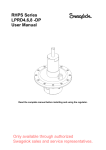
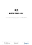
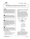
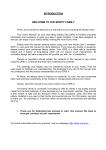
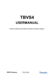
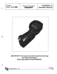
RHPS Series
(LP)RS(H)4,6,8
User Manual
Read the complete manual before installing and using the regulator.
Only available through authorized
Swagelok sales and service representatives.
WARNING
Before removing a regulator from the system for service, you must
▪ depressurize system
▪ purge the system to remove any residual system media left in the regulator.
Contents
Introduction ............................................................................................................................................ 3
Installation .............................................................................................................................................. 5
Operation ................................................................................................................................................ 6
Maintenance ............................................................................................................................................ 7
Testing .................................................................................................................................................... 7
Troubleshooting ..................................................................................................................................... 8
Only available through authorized
Swagelok sales and service representatives.
2
Introduction
Representative drawing of the standard RS(H)4,6,8
1
2
7
8
9
11
12
13
14
body
springhousing
bodyplug
o-ring
valve stem
seat
spring guide
set spring
valve spring
15
16
17
18
19
20
21
22
23
24
diaphragm plate
bottom springguide
knob assembly
diaphragm
o-ring
o-ring
ring
socket head cap screw
ball
valve case
1
2
3
4
7
8
9
11
12
13
14
body
springhousing
o-ring
o-ring
bodyplug
o-ring
valve
seat
spring guide
set spring
valve spring
15
16
20
21
22
23
24
25
27
28
piston plate
piston
o-ring
ring
socket head cap screw
ball
o-ring
back-up ring
o-ring
cover
Only available through authorized
Swagelok sales and service representatives.
3
Representative drawing of the standard LPRS4,6,8
1
2
3
4
5
6
7
8
9
10
body
springhousing assembly
o-ring
back-up ring
cover
bottom cover
bodyplug
o-ring
valve case
valve stem
11
12
13
14
15
16
17
18
19
20
seat
spring guide
set spring
valve spring
diaphragm screw
diaphragm plate
knob assembly
diaphragm
o-ring
o-ring
21
22
23
24
26
27
30
o-ring
nut
socket head cap screw
ball
o-ring
nut
suctiontube
Only available through authorized
Swagelok sales and service representatives.
4
Installation
WARNING
When installing a Swagelok® self-venting regulator, position the vent connection or line
away from operating personnel. Operating personnel must protect themselves from
exposure to system fluids.
CAUTION
Do not use the regulators as a shutoff device.
Connections to System
Before connecting to system, verify the regulator is closed by turning the handle or adjusting screw:
▪ Counterclockwise, when viewed from above, until it stops for pressure reducing regulators,
▪ Clockwise, when viewed from above, until it stops for back-pressure regulators.
The preferred mounting position of the regulator is horizontal with the spring housing facing upwards.
The standard connection of the RS(H)4,6,8 is bspp parallel female. To get a proper sealing across the
thread, Swagelok recommends using bonded seal rings.
If grounding is required, connect a ground wire under a spring housing bolt.
Only available through authorized
Swagelok sales and service representatives.
5
Operation
Note: All handle directions are when viewed from above.
▪ Outlet and control pressure settings are obtained by adjusting the handle (or adjusting screw).
▪ To increase the outlet or control pressure, rotate the handle clockwise.
▪ To decrease the outlet or control pressure, rotate the handle counter-clockwise and vent the
downstream side of the regulator.
▪ Make the final setting in the direction of increasing pressure to obtain the most accurate set
points.
▪ Once fluid is flowing through the system, fine tuning may be required.
▪ Icing of the regulator at high flow rates or high pressure drops may occur if the gaseous media or
atmosphere contains moisture.
▪ An auxiliary upstream filter is recommended for use in all but the cleanest of media.
▪ Installation of a downstream pressure relief is recommended for regulator and system protection.
▪ If the shut-off valve at the outlet side is closed after changing the set pressure, the outlet pressure will
rise a little because of the closing force required for bubble-tight closing of the regulator.
▪ This phenomenon is usually referred to as the “lock-up” and does not indicate a problem with
the regulator.
▪ A decrease in the flow will result in a rise of the outlet pressure.
▪ An increase in the flow will result in a fall of the outlet pressure and is usually referred to as the
“droop”.
▪ This phenomenon does not indicate a problem with the regulator.
▪ A decrease of the inlet pressure will result in a rise of the outlet pressure.
▪ An increase of the inlet pressure will result in a fall of the outlet pressure.
▪ This phenomenon is usually referred to as the “dependency” or “supply pressure effect” and
does not indicate a problem with the regulator.
Only available through authorized
Swagelok sales and service representatives.
6
Maintenance
Required tools for maintenance
▪ a vice to fasten the regulator
▪ pincers to take out the o-rings
▪ a torque wrench
▪ a torque wrench hexagon head key 5 (-LPRS version)
▪ a torque wrench hexagon head key 6
▪ a torque wrench “open end insert tool”, 25 mm
▪ an open end wrench, 17 mm (-LPRS version)
▪ media and temperature compatible lubricant for reassembling threaded parts
▪ media and temperature compatible lubricant for o-rings
▪ Snoop® liquid leak detector
Disassembly instructions
▪ Loosen the hexagon socket head screws and remove the spring housing, spring and bottom spring
guide. Also remove the diaphragm and diaphragm plate or piston and piston plate.
▪ Loosen the bodyplug and remove the valve, valve spring, seat and filter element.
Inspection of disassembled parts
▪ Check all parts for abnormal wear. Replace parts in case of doubt.
Points of attention before assembly
▪ All parts must be clean and undamaged before starting assembly.
▪ Swagelok recommends replacing all o-rings and the diaphragm before assembly.
▪ All threaded parts must be lightly lubricated before assembly to avoid galling of threads.
▪ All o-rings need to be lightly lubricated to improve the lifetime of the o-ring and the performance of the
regulator.
Assembly instructions
Follow the points for disassembly in reverse order to assemble the regulator.
Recommended torques
CAUTION
Only tighten the bolts or parts if the regulator is completely depressurized.
▪
▪
▪
Hexagon socket head screws M6
Hexagon socket head screws M8
Bodyplug
10 N·m (88.5 in.·lb)
25 N·m (221 in.·lb)
20 N·m (177 in.·lb)
Testing
Check the regulator for leakage across the seat, with low- and high inlet pressure.
Check the regulator for leakage across the diaphragm/piston, with low- and high outlet pressure.
Check the required outlet pressure range.
A well performing RS(H)4,6,8 is 100 % bubble tight.
If there is a leakage across the seat or the diaphragm/piston, the damaged parts must be replaced.
Only available through authorized
Swagelok sales and service representatives.
7
Troubleshooting
Problem:
The outlet pressure creeps up, without turning the adjustment knob.
Cause:
A damaged valve and/or seat.
Solution:
Replace the valve and/or the seat.
Problem:
Leakage around the bodyplug.
Cause:
A damaged o-ring/back-up ring or insufficient torque on the body plug.
Solution:
Replace the o-ring/back-up ring or tighten the bodyplug according to the torque specifications.
Problem:
Leakage between the body and the spring housing or through the relief hole at the side of the spring
housing.
Cause:
A damaged diaphragm/piston o-ring or insufficient torque on the bolts.
Solution:
Replace the diaphragm/piston o-ring or tighten the bolts according to the torque specifications.
Problem:
Controlled pressure drops off sharply even when the flow is within regulator capabilities.
Cause:
The regulator filter element or system filter element is clogged.
Solution:
Replace the filter element.
Problem:
The required outlet pressure can not be reached.
Cause:
The inlet pressure is not high enough.
Solution:
Make sure that the inlet pressure is sufficient.
Problem:
The outlet pressure rises too much when going from a dynamic to a static situation.
Cause:
There is too much flow in the dynamic situation.
Solution:
A larger regulator is required.
Check the specific application data with the flow curves in our product literature, if available.
Problem:
The outlet pressure does not drop if the adjustment knob is turned counterclockwise.
Cause:
The regulator is non-venting.
Solution:
A shut-off valve in the outlet line must be opened to reduce the outlet pressure.
Problem:
The outlet pressure has changed without turning the adjustment knob.
Cause:
Changes to the inlet pressure will result in changes to the outlet pressure.
Solution:
Maintain a constant inlet pressure to the regulator. See section “operation” about dependency.
Warranty Information
Swagelok products are backed by The Swagelok Limited Lifetime Warranty.
For a copy, visit swagelok.com or contact your authorized Swagelok representative.
For additional information, see www.swagelok.com.
Caution: Do not mix or interchange parts
with those of other manufacturers.
Swagelok, Snoop – Swagelok Company
© 2010 Swagelok Company
December 2010, R0
MS-CRD-0186
Only available through authorized
Swagelok sales and service representatives.