1
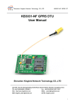
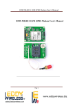
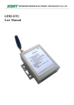
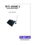
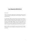
ML8021 GPRS Modem User’s Manual
ML8021 GPRS Modem User’s Manual
Add: 218,2nd floor, 4 Building, Zhuguang Second Industrial Zone, XiLi Town, NanShan
District, ShenZhen China
Tel: +86-755-86507059
E-mail: [email protected]
Skype ID: mellowsales
Website: www.szmellow.com
Page 1
ML8021 GPRS Modem User’s Manual
Content
ML8021 GPRS Modem User’s Manual ....................................................................................... 1
1 Introduction............................................................................................................................ 3
2 Product concept...................................................................................................................... 3
3 Application interface .............................................................................................................. 5
3.1Pin description.............................................................................................................................. 5
3.2 Operating modes......................................................................................................................... 5
3.3 LED indication.............................................................................................................................. 7
3.3.1 Red Led is the power indicates........................................................................................... 7
3.3.2 Yellow Led is the RING indicates......................................................................................... 7
3.3.3 Green Led is the Working state indicates. ......................................................................... 7
4 Mechanical dimension ............................................................................................................ 7
5 Product List............................................................................................................................. 8
Page 2
ML8021 GPRS Modem User’s Manual
1 Introduction
This document defines the ML8021 module series and describes the hardware interface of the
ML8021 module that connects to the customer application and the hardware interface.
This document can help customer quickly understand module interface specifications, electrical
and mechanical details. With the help of this document, associated application notes and user
guide, customer can use ML8021 module to design and set up mobile applications quickly.
2 Product concept
The ML8021 is a Quad-band GSM/GPRS engine that works at frequencies GSM850MHz,
GSM900MHz, DCS1800MHz and PCS1900MHz. The ML8021 features GPRS multi-slot class 12
and supports the GPRS coding schemes CS-1, CS-2, CS-3 and CS-4.
The ML8021 is integrated with Internet service protocols, which are TCP/UDP, FTP and HTTP.
Extended AT commands have been developed for customer to use these Internet service
protocols easily. The modules are fully RoHS compliant to EU regulation.
Table 1 Module key features
Feature
Implementation
Power supply
Single supply voltage 5.0V – 12V,
Frequency bands
● Quad-band: GSM850, GSM900, DCS1800, PCS1900.
● The module can search these frequency bands automatically
● The frequency bands can be set by AT command.
● Compliant to GSM Phase 2/2+
Transmitting power
● Class 4 (2W) at GSM850 and GSM900
● Class 1 (1W) at DCS1800 and PCS1900
GPRS connectivity
● GPRS multi-slot class 12 (default)
● GPRS multi-slot class 1~12 (configurable)
● GPRS mobile station class B
Temperature range
● Normal operation: -35°C ~ +80°C
● Restricted operation: -45°C ~ -35°C and +80°C ~ +85°C 1)
● Storage temperature: -45°C ~ +90°C
DATA GPRS:
● GPRS data downlink transfer: max. 85.6 kbps
● GPRS data uplink transfer: max. 85.6 kbps
Page 3
ML8021 GPRS Modem User’s Manual
● Coding scheme: CS-1, CS-2, CS-3 and CS-4
● Support the protocols PAP (Password Authentication Protocol)
usually used for PPP connections
● Internet service protocols TCP/UDP/FTP/HTTP/MMS
● Support Packet Switched Broadcast Control Channel (PBCCH)
● CSD transmission rates: 2.4, 4.8, 9.6, 14.4 kbps nontransparent
CSD:
● Unstructured Supplementary Services Data (USSD) support
SMS
● MT, MO, CB, Text and PDU mode
● SMS storage: SIM card
FAX
Group 3 Class 1 and Class 2
SIM interface
Port SIM card: 1.8V, 3V, Protected against ESD with a TVS diode
array.
Serial interface
● Support from 4800 bps to 115200 bps, default auto baud rate
● Support TTL/RS232/RS485
● Embed standard AT command(GSM07.05 and 07.07)
Phonebook
management
Support phonebook types: SM, FD, LD, RC, ON, MC
SIM Application Toolkit
Support SAT class 3, GSM 11.14 Release 99
Physical characteristics
79*53*21mm
1) When the module works in this temperature range, the deviations from the GSM specification
might occur. For example, the frequency error or the phase error could increase.
Table 2 Coding schemes and maximum net data rates over air interface
Coding scheme
1 Timeslot
2 Timeslot
4 Timeslot
CS-1:
9.05kbps
18.1kbps
36.2kbps
CS-2:
13.4kbps
26.8kbps
53.6kbps
CS-3:
15.6kbps
31.2kbps
62.4kbps
CS-4:
21.4kbps
42.8kbps
85.6kbps
Page 4
ML8021 GPRS Modem User’s Manual
3 Application interface
3.1Pin description
Table 3 Pin description
PIN TTL
RS-232
RS-485
1
NC
NC
NC
2
TXD
TXD
A
3
RXD
RXD
B
4
NC
NC
NC
5
GND
GND
GND
6
NC
NC
NC
7
NC
CTS
NC
8
NC
RTS
NC
9
NC (Power for Option) NC (Power for Option) NC (Power for Option)
3.2 Operating modes
The table below briefly summarizes the various operating modes referred to in the following
chapters.
Table 4 Overview of operating modes
Mode
Function
Normal
operation
GSM/GPRS
SLEEP
The module will automatically go into SLEEP mode if
DTR is set to high level and there is no interrupt (such
as GPIO interrupt or data on serial port).
In this case, the current consumption of module will
reduce to the minimal level.
Page 5
ML8021 GPRS Modem User’s Manual
During SLEEP mode, the module can still receive
paging message and SMS from the system normally.
GSM IDLE
Software is active. The module has registered to the
GSM network, and the module is ready to send and
receive.
GSM TALK
GSM connection is going. In this mode, the power
consumption is decided by the configuration of Power
Control Level (PCL), dynamic DTX control and the
working RF band.
GPRS IDLE
The module is not registered to GPRS network. The
module is not reachable through GPRS channel.
GPRS
The module is registered to GPRS network, but no
GPRS PDP context is active. The SGSN knows the
Routing Area where the module is located at.
STANDBY
GPRS
READY
GPRS DATA
The PDP context is active, but no data transfer is going
on. The module is ready to receive or send GPRS data.
The SGSN knows the cell where the module is located
at.
There is GPRS data in transfer. In this mode, power
consumption is decided by the PCL, working RF band
and GPRS multi-slot configuration.
POWER DOWN
Normal shutdown by sending the “AT+QPOWD=1” command, using the
PWRKEY pin. The power management ASIC disconnects the power supply
from the base band part of the module, and only the power supply for
the RTC is remained. Software is not active. The serial interfaces are not
accessible. Operating voltage (connected to VBAT) remains applied.
Minimum
functionality
mode (without
removing power
supply)
Use the “AT+CFUN” command can set the module to a minimum
functionality mode without removing the power supply. In this case, the
RF part of the module will not work or the SIM card will not be accessible,
or both RF part and SIM card will be closed all, but the serial port is still
accessible. The power consumption in this case is very low.
Note: The module is set to auto baud rate mode (AT+IPR=0) in default configuration. In the auto
baud rate mode, the URC “RDY” after powering on is not sent to host controller. AT command
can be sent to the module 2-3 seconds after the module is powered on. Host controller should
firstly send an “AT” or “at” string in order that the module can detect baud rate of host
controller, and it should send the second or the third “AT” or “at” string until receiving “OK”
string from module. If you need to using fixed baud rate, Then an “AT+IPR=x; &W” should be
sent to module and save the configuration to flash memory of module. After these
Page 6
ML8021 GPRS Modem User’s Manual
configurations, the URC “RDY” would be received from the Serial Port of module every time
when the module is powered on. Refer to Chapter “AT+IPR” in AR command manual.
3.3 LED indication
3.3.1 Red Led is the power indicates.
3.3.2 Yellow Led is the RING indicates.
3.3.3 Green Led is the Working state indicates.
The Working state of this LED is list in the table 6.
Table 6 Working state of the Green LED
state
Module Function
Off
The module is not running(Power Off)
64ms On/800ms Off
The module is not synchronized with network
64ms On/2000ms Off The module is synchronized with network
64ms On/600ms Off
GPRS data transfer is ongoing.
4 Mechanical dimension
Page 7
ML8021 GPRS Modem User’s Manual
5 Product List
Name
Unit
Quantity
Describe
ML8021
Item
1
Module
Antenna
Item
1
Standard Supply
Power Adapter
Item
1
DC 5V 2A
RS-232 Cable
Item
1
Standard Supply
Page 8
Picture