1
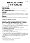
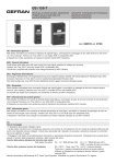
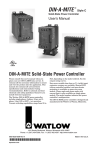
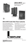
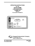
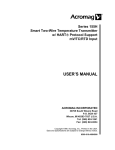
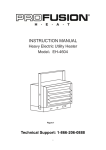
VPAC
User's Manual
Solid State Relay
Power Control
Watlow Controls
1241 Bundy Boulevard, P.O. Box 5580, Winona, MInnesota USA 55987-5580
Phone: 507/454-5300, Fax: 507/452-4507 http://www.watlow.com
0600-0028-0000 Rev B
December, 1999, North American English
Supersedes:
WVPC-XUMN Rev A00
$5.00
Made in the U.S.A.
Printed on Recycled Paper
General Description
Specifications
The VPAC Series Power Controls are a family of Solid State Relay
(SSR) controls for electric heating applications. The VPAC
provides output power proportional to the input command signal
from a temperature control. The single phase VPAC-01 can be
ordered in either ON/OFF (solid state contactor), burst fired or
phase angle firing mode. The three phase, two leg VPAC-32 is for
solid state contactor or burst fired (loop powered) operation only.
Starting Out
Model Number
(1821)
VPAC Series
V__-___-__-___
Phase
01
= Single Phase
32
= Three Phase, Two Leg,
Burst fired (BL) or SS
contactor (CA, CD) only.
Voltage
12
= 120V~(ac)
24
= 240V~(ac)
27
= 277V~(ac)
38
= 380V~(ac)
41
= 415V~(ac)
48
= 480V~(ac) (in 25A and up only)
Current
10
= 10Amps
25
= 25Amps
40
= 40Amps
50
= 50Amps
75
= 75Amps
Control Mode
BL0 = Burst fired, variable time base, loop powered,
4-20mA input-08-5399
*BT1 = Zero cross, variable time base, transformer powered.
Single phase only, 4-20mA input calibration.
*BT2 = Zero cross, variable time base, transformer powered.
Single phase only. 0 to 5VDC input calibration.
Can be used for manual potentiometer input.
*AT1 = Phase angle, transformer powered. Single phase only.
4-20mA input calibration.
*AT2 = Phase angle, transformer powered. Single phase only.
0 to 5VDC input calibration. Can be used for manual
potentiometer input.
CA0 = Contactor, AC Input
CD0 = Contactor, DC Input
*Transformer included for AT+ and BT.
Accessory
08-5362 = Manual Control Kit, 1K Potentiometer
(08-5362 for use with AT+ and BT Cards only)
Semiconductor Fuses for VPAC Through 75 Amps
Amp
Voltage
Rating
Rating
VPAC SCRs and SSRs
10 amp
12
600
25 amp
32
600
40 amp
50
700
50 amp
63
700
75 amp
100
500
Bussmann
P/N
Watlow
Fuse
P/N
Watlow
Fuse Holder
P/N
FWC12A10F
FWC32A10F
FWP50A14F
FWP63A22F
FWP100A22F
17-8012
17-8032
17-8050
17-8063
17-8100
17-5110
17-5110
17-5114
17-5122
17-5122
Warranty
The VPAC is warranted to be free of defects in material and workmanship
for 36 months after delivery to the first purchaser for use, providing that the
units have not been misapplied. Since Watlow has no control over their
use, and sometimes misuse, we cannot guarantee against failure.
Watlow's obligations hereunder, at Watlow's option, are limited to
replacement, repair or refund of purchase price, and parts which upon
examination prove to be defective within the warranty period specified.
This warranty does not apply to damage resulting from transportation,
alteration, misuse, abuse, or improper fusing.
Watlow VPAC User's Manual
2
(1822)
Solid State Relay Power Control with Heat Sink
• Solid state contactor, AC input (CA)
• Solid state contactor, DC input (CD)
Optional Loop-Powered Control Card
• Burst firing (zero cross) control, 4-20mA (BL)
Optional Transformer-Powered Control Card
• Burst firing (zero cross) control, Process Input, 1Ø only (BT)
• Phase angle control, Process input, 1Ø only (AT+)
• SDA Shorted SSR Alarm (for Zero cross only)
Line Voltage (50/60Hz)
• 120V~(ac) operation
• 208/240V~(ac) operation
• 277V~(ac) operation
• 380V~(ac) operation
• 415V~(ac) operation
• 480V~(ac) operation
Solid State Relay Control
• Single phase, single SSR
• Three phase, two leg control for three wire (non-grounded load),
dual SSR.
• Resistive load only
Inputs
• Solid state contactor, AC input (CA)
ON, 90 to 240V~(ac); OFF, 0 to 10V~(ac)
• Solid state contactor, DC input (CD)
ON, 3 to 32VDC; OFF, 0VDC
• Burst firing (zero cross) control card (BL)
Input 4 to 20mA only
Bias and Gain adjustable
Input impedance 500 minimum
• Burst firing (zero cross) control card (BT), 1Ø only
Input factory adjusted for 4-20mA
Bias and Gain adjustable, 0 to 12VDC/0 to 25mA
Input impedance 300 (clip R-22 for 5K , voltage input)
• Phase angle control card (AT+), 1Ø only
Input factory adjusted for 4-20mA
Bias and Gain adjustable, 0 to 12VDC/0 to 25mA
Input impedance 300 (clip R-2 for 5K , voltage input)
Soft start 10 seconds (approx.)
• 120/240V~(ac) or 480V~(ac) to 24V~(ac) power transformer
included, model dependent for AT+ and BT options.
Outputs
• 120V~(ac) through 480V~(ac)
• 10-75A
Operating Ambient
• Temperature - 0 to 50°C
• RH - 0 to 90%, non-condensing
Specification subject to change without notice.
Returns
1. Call Customer Service, 507-454-5300, for a Return Material
Authorization (RMA) number before returning any item for repair. We
need:
• Ship to address
• Bill to address
• Contact name
• Phone number
• Ship via
• Your P.O. #
• Symptoms and/or special instructions
• Name & phone of person returning the material.
2. Prior approval and an RMA number, from the Customer Service
Department, is needed when returning any unused product for credit.
Make sure the RMA number is on the outside of the carton, and on all
paperwork returned. Ship Freight Prepaid.
3. In cases of manufacturing defect, we will enter a repair order,
replacement order, or issue credit for material. A 25% restocking
charge is applied for all returned stock controls and accessories.
4. If the unit is unrepairable, it will be returned to you with a letter of
explanation. Repair costs will not exceed 50% of the original cost.
VPAC Dimensions and Mounting
C
Starting Out
E
ç
UP
∫
WARNING:
VPAC mounting and
spacing must conform to
local, state and national
safety codes. Failure to
conform to codes could
result in death or personal injury, or damage
to equipment.
A
H
B
ç
CAUTION:
W
UP
Mount units with heat
sink fins oriented
vertically. Failure to do
so could result in unit
failure and damage to
the process.
D
NOTE: *The 50Amp Single Phase width mounting dimension
includes four mounting clips (#56-0308) instead of the 1/2 round
cutouts.
NOTE: 3-Phase, 2-Leg 10-40A use 2 heat sinks for overall
dimensions.
NOTE: Mounting dimensions show maximum possible height and
depth with terminal-mounted control card attached. Unit height and
depth varies with control card configuration.
Maximum Overall Dimensions
Amps
10
25
40
Height (H)
5.60"
5.50"
6.30"
Width (W) Depth (D)
4.50"
1.50"
4.75"
4.75"
3.60"
3.60"
Mounting Dimensions
V01 10-40A
A
3.00"
B
0.50"
C
0.15"
E
4.20"
Fan Cooled
No
2.00"
4.50"
0.50"
0.50"
0.15"
0.15"
4.45"
4.45"
No
No
C
E
Fan Cooled
V32 10-40A
Amps
Height (H)
Width (W) Depth (D)
10
25
5.60"
5.50"
9.00"
9.50"
1.50"
3.60"
40
6.30"
9.50"
3.60"
A
B
3.00"
2.00"
0.50"
0.50"
0.15"
0.15"
4.20"
4.45"
No
No
4.50"
0.50"
0.15"
4.45"
No
A
7.00"
B
N/A
C
N/A
E
5.90"
Fan Cooled
No
7.00"
1.00"
0.15"
4.70"
Yes
A
7.00"
B
1.00"
C
0.15"
E
4.70"
Fan Cooled
Yes
7.00"
1.00"
0.15"
4.70"
Yes
V01 50-75A
C
Amps
50A
75A
Height (H)
9.00"
10.50"
Width (W) Depth (D)
*6.90"
3.50"
5.00"
5.50"
V32 50-75A
Amps
50A
75A
Height (H)
10.50"
10.50"
Width (W) Depth (D)
5.00"
5.50"
5.00"
5.50"
Watlow VPAC User's Manual
3
Mount 120/240V Transformer AT+/BT Power
Mount Semiconductor Fuses
The AT+ or BT transformer powers the AT+ or BT control card.
Mount the transformer within 12 in. (30.5cm) of the VPAC it
connects to.
Starting Out
0.4"
0.5"
0.2"
0.3"
(12mm) for 15A, 30A fuse
(13mm) for 50A fuses
(6mm) for 15A, 30A fuses
(8mm) for 50A fuses
0.2" (5mm)
Mtg. Holes
1.7"
(45mm)
Panel
2.4"
(60mm)
0.8"
(21mm)
120/240V
Xformer
16-0238
0.2"
(56mm)
2.0"
(51mm)
0.4"
(10mm)
1.4"
(35mm)
Mount 15/30A Semiconductor Fuse
1.3"
(33mm)
∫
4.5" (114mm)
3.9" (100mm)
0.7"
(17mm)
1.7"
(43mm)
2.5"
(64mm)
0.4" (10mm)
Guide Lug
Hole
Mount 277 to 480V Transformers AT+/BT Power
0.2" (6mm)
Mounting Hole
The AT+ or BT transformer powers the AT+ or BT control card.
Mount the transformer within 12 in. (30.5cm) of the VPAC it
connects to.
0.2" (5mm)
Mtg. Holes
#8 Screw
1.3"
(32mm)
0.6"
(16mm)
1.5"
(38mm)
Mount 50/100A Semiconductor Fuse
∫
5.5" to 5.6" (140 to 143mm)
5.0" to 5.1" (127 to 130mm)
4.6" to 4.7"
(117 to 120mm)
Blk
Wht
Transformer
2.4"
(61mm)
Connector to
AT+ or BT Card
0.4" (10mm)
Guide Lug
Hole
0.2" (6mm)
Mounting Hole
1.3"
(32mm)
0.6"
(16mm)
1.5"
(38mm)
1.5"
(38mm)
Mount Semiconductor Fuses
Panel
.3"
(6mm)
Mount optional semiconductor fuses near the VPAC. Mounting
must conform to code requirements. Wiring diagrams show
proper connections.
ç
∫
WARNING:
1.7"
(42mm)
Watlow VPAC User's Manual
4
Fuse mounting and spacing must conform to local, state and
national safety codes. Failure to conform to codes could
result in damage to equipment and/or injury to personnel.
Single Phase Wiring
Starting Out
1Ø Wiring for AC & DC Input Contactor
10-40A, Models (CA or CD)
ç
L1
∫1
∫2
∫1
WARNING:
L2
Semiconductor
Fuse
Limit Contactor
L1
T1
Contacts
(if required)
CD
Wiring must conform to National
Electric Code (NEC) safety standards,
as well as locally applicable codes.
Failure to do so could result in death or
personal injury.
ç
∫2
WARNING
Wiring examples show L2 in 240V~(ac)
or 480 V~(ac) configuration. In
120V~(ac) applications, L2 is neutral and
must not be fused or switched. Failure
to follow this guideline could result in
death or personal injury.
VDC
V~(ac) or VDC Input
Command Signal
Depending on Model Ordered
1Ø Wiring, 4-20mA Burst, 10-40A (BL)
L2
L1
∫1
∫2
1Ø Wiring, 4-20mA Burst, 50 & 75A (BL)
Semiconductor
Fuse
Limit Contactor
Contacts
(if required)
L1
T1
L2
V~(ac)
Semiconductor
Fuse
SBL
L1
∫1
∫2
Limit Contactor
(if required)
4-20mA
Input
L1 L2 T1 T2
4-20mA
120V~(ac) Fan Power
20 Watts Max. - 75A Only
(Customer Supplied)
Separate Disconnect Required
Watlow VPAC User's Manual
5
Single Phase Wiring
Starting Out
1Ø Wiring, 4-20mA Burst (BT)
1Ø Wiring, 4-20mA Phase Angle (AT+)
ç
∫1
∫2
Wiring must conform to National Electric
Code (NEC) safety standards, as well as
locally applicable codes. Failure to do
so could result in death or personal
injury, or damage to equipment.
L2
ç
L1
L1
1A Fuses
∫2
WARNING:
Semiconductor
Limit Contactor Contacts Fuse
(if required)
∫1
WARNING:
T1
Customer Supplied Wiring
240V~(ac) Power to
Transformer
4
Wiring examples show L2 in 240V~(ac)
or 480 V~(ac) configuration. In
120V~(ac) applications, L2 is neutral
and must not be fused or switched.
Failure to follow this guideline could
result in death or personal injury.
AT+
1
24V~(ac) Power to
AT+ or BT Card
BT
R2 (270 ) ->
R22
(300 )
Customer Supplied Wiring
120V~(ac) Power to Transformer
L2-Wht
L1-Blk
Process +
Input -
4
+
-
W
CCW
˜
1
24V~(ac) Power
to
AT+ or BT Card
CW
L2-Wht
L1-Blk
Transformer
Customer Supplied Wiring
277 to 480V~(ac) Power to Transformer
When using potentiometer input, remove
remove resistor R22 or R2 for 5K input
impedance, also for 1-5VDC input.
24V~(ac) Power
to
AT+ or BT Card
NOTE: The control transformer must be on the same phase as the load. See
wiring diagram above. All hot lines to the transformer should be fused at 1
Amp with the proper line voltage.
NOTE: For manual control, a 1K
potentiometer may be connected to the
BT or AT+ card input terminals. Watlow
offers a kit as Manual Control Kit, part
number, 08-5362. Using this
potentiometer requires removing the
specified control card resistor for
higher impedance.
Bias and gain adjustment is required
when changing from 4-20mA input to a
manual control input or a voltage input.
Watlow VPAC User's Manual
6
3-Phase, 2-Leg Wiring
Starting Out
∫
3Ø Wiring for AC & DC Input Contactor
10-40A, Models (CA or CD)
ç
Wiring must conform to National Electric
Code (NEC) safety standards, as well as
locally applicable codes. Failure to do so
could result in death or personal injury,
or damage to equipment.
Semiconductor
Fuses
L1
L2
L3
Limit Contactor
(if required)
T1
∫
WARNING:
T3
VDC
T2
90-240V~(ac) AC Input +
3Ø Wiring, DC Contactor, 50 & 75 A (BL) (CD)
Semiconductor
Fuses
T2
L1
L2
L3
∫
T1
Limit Contactor
(if required)
T3
L1 T1
L3 T3
SBL
+ -
3Ø Wiring, Burst Fired, 4-20mA, 10-40 A (BL)
Semiconductor
Fuses
4-20mA
Fan
Fan
L1
L2
L3
Limit Contactor
(if required)
∫
120/240V~(ac) Fan Power
(model # dependent)
20 Watts Max.
(Customer Supplied)
Separate Disconnect Required
T1
T2
- +
+ - +-
T3
4-20mA +
Input Watlow VPAC User's Manual
7
5.
Troubleshooting
To isolate a system problem involving the VPAC, answer these
questions:
• Are inputs to the VPAC present?
• Are outputs from the VPAC present?
• Are all connections good?
• Is the load good?
• Is line voltage within specification?
• Are temperature control signals present? If so, then the VPAC
power control itself may be the problem. The problem may be with
the VPAC's control card, transformer or solid state relay. Use the
table below to assist with troubleshooting.
Starting Out
Symptom
Probable Cause
Corrective Action
No output
Fuses blown
Incorrect input wiring
Incorrect input signal
Input signal reversed
Input signal not adjusted
Wrong or missing
control card
Check and replace fuses.
Verify input wiring.
Check temp. control output.
Verify input wiring.
“See Bias and Gain Adjustment.”
Missing load wiring
Transformer hot
Incorrect transformer
Uncontrolled
output full ON
Bad control card,
or Bias and Gain
out of adjustment
Bad transformer
Bad SSR
Verify input wiring.
Check transformer connections.
Verify load wiring
The SSR(s) will not
function without a load.
Check product & transformer
labels (AT+ & BT only).
Disconnect control card, try again.
If no output, SSR is okay. Check
Bias and Gain Adjustment.
Unplug transformer wires
and try again. (AT+ & BT only.)
If full ON or half ON output
present with no control card
and no transformer, solid state
relay is bad; replace it.
Bias And Gain Adjustments
The VPAC bias and gain can be adjusted for the output of most
standard, proportional output temperature controls. Bias and gain
is factory set for an input control signal (0-5VDC or 4-20mA), but
may require minor adjustments to match the output of a specific
temperature control.
We recommend that bias and gain adjustment be performed using
a dummy load. In some applications, a dummy load may be
required if the controlled load can not be turned full ON. A dummy
load can be easily made by connecting 150 watt lamps in series to
match the operating voltage of the VPAC. Use the following steps
to make adjustments.
1.
2.
3.
4.
Connect an AC voltmeter across the load or dummy load of
the VPAC. Connect a DC voltmeter across, or milliampmeter
in series with, the input signal from the temperature controller.
Apply power to the system.
Set the output signal of the temperature controller to zero or
its minimum output. Adjust the bias potentiometer slowly until
the VPAC output just comes ON. Then turn it in the opposite
direction until the output is just full OFF as observed on the
output voltmeter.
Adjust the output of the temperature controller to full ON
(5VDC, 20mA, etc.). Adjust the gain potentiometer until the
VPAC output is just full ON.
Watlow VPAC User's Manual
8
6.
Repeat Steps 3 and 4 until the VPAC turns full ON with a full
ON signal from the temperature control, and full OFF with the
minimum input signal from the temperature control. Steps 3
and 4 may need to be repeated a few times (an adjustment
made on one of the potentiometers affects the adjustment of
the other potentiometer).
Remove power, disconnect the meters, and reconnect the
controlled load to the VPAC if required.
Replace SSR
Screw, 2 ea., #8-32
See Note 4.
Belleville Washer, #8
See Note 4.
Solid State Relay
See Note 3.
Thermal pad or
a thin coat of thermal
joint compound
(Dow DC-340)
Heat Sink (typical)
1.
2.
3.
4.
Surface must be clean and flat.
Use a thermal pad or a thin coat of thermal joint compound
(Dow DC-340 or equivalent).
Mount the SSR to the heat sink.
Use Belleville (spring) washers and tighten screws alternately
until the spring is deflected slightly.
ç
CAUTION:
UP
Heat sink must be mounted so that the fins are vertically aligned.
ç
CAUTION:
Heat sensitive component; ambient temperature must not exceed
122°F (50°C). If overheated, unit could fail.
ç
CAUTION:
Heat sensitive component; do not mount SSRs on panels that are
painted, plastic, steel or stainless steel. These materials will not
remove heat generated by the SSR. If overheated, unit could fail.
Feedback
Your comments and suggestions on this manual are welcome.
Please send them to: Technical Writer, Watlow Controls, P.O. Box
5580, Winona, MN 55987-5580, or call (507) 454-5300 or fax
(507) 45204507. The VPAC Users Manual is copyrighted by
Watlow Winona, Inc., © December 1999, with all rights reserved.
(1820)