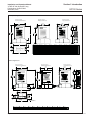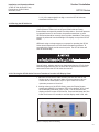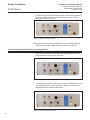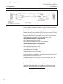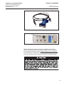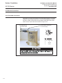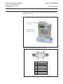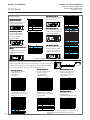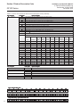
1
Installation and Operation Manual
X-TMF-GF100-Series-MFC-eng
Part Number: 541B137AAG
November, 2015
GF100 Series
Brooks® GF100 Series
High Purity/Ultra-High Purity Digital Thermal
Mass Flow Devices
Model GF125 Analog I/O
Model GF125 Digital I/O
Model GF135 Analog I/O
Model GF121 Analog I/O
GF100 Series
Installation and Operation Manual
X-TMF-GF100-Series-MFC-eng
Part Number: 541B137AAG
November, 2015
Installation and Operation Manual
X-TMF-GF100-Series-MFC-eng
Part Number: 541B137AAG
November, 2015
GF100 Series
Dear Customer,
We appreciate this opportunity to service your flow measurement and control requirements with a Brooks
Instrument device. Every day, flow customers all over the world turn to Brooks Instrument for solutions to their gas
and liquid low-flow applications. Brooks provides an array of flow measurement and control products for various
industries from biopharmaceuticals, oil and gas, fuel cell research and chemicals, to medical devices, analytical
instrumentation, semiconductor manufacturing, and more.
The Brooks product you have just received is of the highest quality available, offering superior performance,
reliability and value to the user. It is designed with the ever changing process conditions, accuracy requirements
and hostile process environments in mind to provide you with a lifetime of dependable service.
We recommend that you read this manual in its entirety. Should you require any additional information concerning
Brooks products and services, please contact your local Brooks Sales and Service Office listed on the back cover
of this manual or visit www.BrooksInstrument.com.
Yours sincerely,
Brooks Instrument
Installation and Operation Manual
X-TMF-GF100-Series-MFC-eng
Part Number: 541B137AAG
November, 2015
GF100 Series
THIS PAGE WAS
INTENTIONALLY
LEFT BLANK
Installation and Operation Manual
X-TMF-GF100-Series-MFC-eng
Part Number: 541B137AAG
November, 2015
Paragraph
Number
Contents
GF100 Series
Page
Number
Section 1 General Information
1-1
Introduction ................................................................................................................................... 1-1
1-2
How to Use This Manual ............................................................................................................... 1-1
1-3
Product Support References ......................................................................................................... 1-2
1-4
Notice and Caution Statements ..................................................................................................... 1-2
1-5
Product Warranty .......................................................................................................................... 1-2
1-6
How to Order a GF100 Series Device ........................................................................................... 1-2
1-7
Industry Standard References ....................................................................................................... 1-2
1-8
GF100 Series Gas Table ............................................................................................................... 1-2
1-9
Glossary of Terms and Acronyms ................................................................................................. 1-2
1-10
Description .................................................................................................................................... 1-5
1-11
Specifications for GF100 Series Devices ...................................................................................... 1-8
Section 2 Installation
2-1
General ......................................................................................................................................... 2-1
2-2
Receipt of Equipment .................................................................................................................... 2-1
2-3
Recommended Storage Practice .................................................................................................. 2-1
2-4
Return Shipment ........................................................................................................................... 2-2
2-5
Transit Precautions ....................................................................................................................... 2-2
2-6
Removal from Storage .................................................................................................................. 2-2
2-7
Gas Connections ........................................................................................................................... 2-2
2-8
In-Line Filter .................................................................................................................................. 2-2
2-9
Mechanical Installation .................................................................................................................. 2-3
2-10
Flow Controller Installation Arrangement ...................................................................................... 2-4
2-11
Purge the Gas Supply Line Before GF100 Series Installation ....................................................... 2-5
2-12
Position and Mount the GF100 Series .......................................................................................... 2-6
2-13
Perform a Leak Test ...................................................................................................................... 2-8
2-14
Zeroing Setup Process .................................................................................................................. 2-8
2-15
Zeroing the GF100 Series ............................................................................................................. 2-9
2-15-1 Zeroing the GF100 Series Pressure Transducer from the LCD Display Panel ............................. 2-9
2-15-2 Zeroing GF100 Series Flow from LCD Display Panel .................................................................. 2-10
2-16
Performance Checks ................................................................................................................... 2-11
2-17
Introduction to the MultiFloTM Configurator ................................................................................... 2-11
2-18
Using the MultiFlo Configurator .................................................................................................... 2-11
2-19
Electrical Connections .................................................................................................................. 2-14
2-19-1 DeviceNet Connections ................................................................................................................ 2-14
2-19-2 Analog/RS485 Connections ......................................................................................................... 2-15
2-20
GF135 Inlet Valve Installation ....................................................................................................... 2-17
2-21
GF135 Commissioning ................................................................................................................. 2-18
Section 3 Operation
3-1
General ......................................................................................................................................... 3-1
3-2
Theory of Operation for Flow Measurement ................................................................................. 3-1
Section 4 Maintenance & Troubleshooting
4-1
Overview ....................................................................................................................................... 4-1
4-2
Maintenance .................................................................................................................................. 4-1
4-3
Troubleshooting............................................................................................................................. 4-3
4-4
Troubleshooting Checklist ............................................................................................................. 4-3
4-5
GF100 Series Troubleshooting Guide ........................................................................................... 4-4
Section 5 Product Description Code
5-1
Overview ....................................................................................................................................... 5-1
Appendix A: GF100 Series Gas Table
A-1
Overview ....................................................................................................................................... A-1
i
Contents
GF100 Series
Installation and Operation Manual
X-TMF-GF100-Series-MFC-eng
Part Number: 541B137AAG
November, 2015
Appendix B: GF100 Series Patents
B-1
Overview ....................................................................................................................................... B-1
Appendix C: Essential Instructions
C-1
Overview ....................................................................................................................................... C-1
Warranty, Local Sales/Service Contact Information....................................................................... Back Cover
Figure
Number
1-1
1-2
1-3
1-4
1-5
1-6
2-1
2-2
2-3
2-4
2-5
2-6
2-7
2-8
2-9
2-10
2-11
2-12
2-13
2-14
2-15
2-16
2-17
3-1
GF100 Series High Performance Gas Flow Controller Analog and Digital .................................... 1-1
LCD Display .................................................................................................................................. 1-7
Dimensions - GF100/GF120/GF125 Series ................................................................................. 1-13
Dimensions - GF135, DeviceNet .................................................................................................. 1-14
Dimensions - GF135, RS485 ....................................................................................................... 1-15
Dimensions - GF101/GF121/GF126 ............................................................................................ 1-16
Typical Gas Supply Arrangement with Non-PTI MFC .................................................................... 2-4
Typical Gas Supply Arrangement with PTI MFC ........................................................................... 2-4
GF100 Series Mounting Attitude Positions .................................................................................... 2-6
GF100 Series Mounted to K1 Series Substrate Blocks ................................................................. 2-7
Mounting Screws Torque Pattern .................................................................................................. 2-8
Display with PSI Reading .............................................................................................................. 2-9
Display Reading Zero PSI ............................................................................................................ 2-10
Display Set to %FS ...................................................................................................................... 2-10
% Flow Display Set to Zero .......................................................................................................... 2-10
MultiFlo Cable Adapter ................................................................................................................. 2-12
USB-RS485 Converter (214F027AAA) ........................................................................................ 2-13
Diagnostic Port ............................................................................................................................. 2-13
GF100 Series DeviceNet Connection .......................................................................................... 2-14
GF100 Series with 9-Pin Analog Connector ................................................................................. 2-15
Analog 9-Pin Connector (M) ......................................................................................................... 2-15
GF100 Series Electrical Interface Options ................................................................................... 2-16
GF135 Series Showing Inlet/Outlet Pneumatic Isolation Valve Lines ........................................... 2-17
GF100 Series Operating Principles ............................................................................................... 3-2
Table
Number
ii
1-1
1-2
1-3
1-4
1-5
1-6
1-7
2-1
2-2
2-3
4-1
4-2
5-1
5-2
5-3
A-1A
A-1B
A-1C
B-1
Page
Number
Page
Number
Industry Standard References ....................................................................................................... 1-3
Terms and Acronyms .................................................................................................................... 1-4
Specifications for Standard GF100/GF120/GF125 Series ............................................................. 1-9
Specifications for High Accuracy (HA) GF125 Series .................................................................. 1-10
Specifications for Safe Delivery System (SDS) GF120 Series ..................................................... 1-10
Specifications for GF135 Series ................................................................................................... 1-11
Specifications for GF101/GF121/GF126 Series ........................................................................... 1-12
K1 Series Fasteners ...................................................................................................................... 2-7
K1 Substrate Torque Data ............................................................................................................. 2-7
Gas and Flow Ranges - MultiFlo Configurable - N2 Equivalent ................................................... 2-11
Environmental Factors .................................................................................................................. 4-3
GF100 Series Troubleshooting Guide ........................................................................................... 4-4
GF100, GF120 & GF125 Series Product Description Code .......................................................... 5-1
Model GF135 Product Description Code....................................................................................... 5-3
GF101, GF121 & GF126 Series Product Description Code .......................................................... 5-4
GF100 Series Gas Table - Codes 1-108, Bins SH40 to SH50 ...................................................... A-1
GF100 Series Gas Table - Codes 109-875, Bins SH40 to SH50 .................................................. A-2
GF100 Series Gas Table - Codes 878-5022, Bins SH40 to SH50 ................................................ A-3
GF100 Series Patents ................................................................................................................... B-1
Section 1 Introduction
Installation and Operation Manual
X-TMF-GF100-Series-MFC-eng
Part Number: 541B137AAG
November, 2015
GF100 Series
1-1 Introduction
Designed for semiconductor, MOCVD , and other gas flow control
applications that require a high purity all-metal flow path, the Brooks
GF100 Series mass flow controllers and meters deliver outstanding
performance, reliability, and flexibility. Process throughput and yield are
maximized while process costs are reduced by the GF100 Series featuring:
• Ultra fast settling time for quick start up and very rapid process steps
• MultiFlo™ gas and range configurability enabling reconfiguration without
removing device from the gas line
• An independent diagnostic/service port to troubleshoot or change flow
conditions without removing the mass flow controller from service
• Long-term stability due to extremely low wetted surface area, and
corrosion resistant Hastelloy® sensor and valve seat
Optional model variations including—pressure transient insensitivity (PTI),
High Accuracy (HA), Safe Delivery System (SDS)
Figure 1-1 GF100 Series High Performance Gas Flow Controller Analog and Digital
1-2 How to Use This Manual
This manual is intended to provide the user with all the information
necessary to install, operate, troubleshoot and maintain these thermal
mass flow devices. The manual is organized in the following sections:
Section 1 Introduction
Section 2 Installation
Section 3 Operation
Section 4 Maintenance and Troubleshooting
Section 5 Product Description Code
Appendix A GF100 Series Gas Table
Appendix B GF100 Series Patents
Appendix C Essential Instructions
Warranty, Local Sales/Service Contact Information
It is recommended that this manual be read in its entirety before attempting
to operate or repair these devices.
1-1
Section 1 Introduction
Installation and Operation Manual
X-TMF-GF100-Series-MFC-eng
Part Number: 541B137AAG
November, 2015
GF100 Series
1-3 Product Support References
Refer to www.BrooksInstrument.com for Brooks sales and service
locations and to obtain other documents that support the GF100 Series.
Those documents include:
- Brooks MultiFloTM Configurator Quick Start Manual:
X-SW-MultiFlo-Config-QS-eng. part Number 541B167AAG
- Brooks GF100 Series data sheets:
DS-TMF-GF100-Series-MFC-eng
DS-TMF-GF135-Series-MFC-eng
DS-TMF-GF121-Series-MFC-eng
1-4 Notice and Caution Statements
Warning, caution and notice statements are located throughout this manual
in the ANSI format. A WARNING statement indicates a potentially
hazardous situation which, if not avoided, COULD result in death or serious
injury. A CAUTION statement indicates a potentially hazardous situation
which, if not avoided, MAY result in minor or moderate injury. It may also be
used to alert against unsafe practices. A NOTICE statement describes
specific information that requires special attention.
1-5 Product Warranty
Product warranty information can be found on the Back Cover of this
Manual and on the Brooks website at www.BrooksInstrument.com. This
information provides general warranty information, limitations, disclaimers,
and applicable warranty periods according to product group.
1-6 How to Order a GF100 Series Device
Refer to Section 5.
1-7 Industry Standard References
Refer to Table 1-1.
1-8 GF100 Series Gas Table
Refer to Appendix A.
1-9 Glossary of Terms and Acronyms
Refer to Table 1-2
1-2
Installation and Operation Manual
X-TMF-GF100-Series-MFC-eng
Part Number: 541B137AAG
November, 2015
Section 1 Introduction
GF100 Series
Table 1-1 Industry Standard References
Reference Number
MIL-STD-810
SEMI E12
SEMI E16
SEMI E17
SEMI E18
SEMI E27
SEMI E28
SEMI E52
SEMI E54
SEMI E56
SEMI E66
SEMI E67
SEMI E68
SEMI E69
SEMI E80
SEMI E16-90
SEMI F19
SEMI F20
SEMI F36
SEMI F37
SEMI F44
SEMI F45
SEMI F47
SEMI S2
SEMI S9
SEMI S10
SEMI S12
Reference Description
Method 514.4, Category 1, Transportation Requirement
Method 516.4, Procedure 1, Functional Shock Test Requirement
Standard temperature and pressure
Guideline for determining and describing MFC leak rates
Guideline for MFC transient characteristics tests
Guideline for temperature specifications of the MFC
Standard for MFC and MFM linearity
Guideline for pressure specifications for the MFC
Practice for referencing gases used in digital MFCs
Sensor actuator network connections for DeviceNet
Test method for detemining accuracy, linearity, repeatability, short-term
reproducibility, hystereses of thermal MFCs
Test method for determining particle contribution by MFCs
Test method for determining reliabilty of MFCs
Test method for determining warm-up time of MFCs
Test method for reproducibilty and zero drift for thermal MFCs
Test method for determining attitude sensitivity of MFCs
Guidelines for determining and describing mass flow controllers leak rates
Specification for the finish of the wetted surface of electro polished
216L stainless steel components
Specifications for 316L stainless steel bar, extruded shapes, plate, and
investment castings for components used in ultra-high purity semi
manufacturing applications
Guide for dimensions and connections of gas distribution components
Method for determination of surface roughness parameters for gas
distribution system components
Guideline for standardization of machined stainless steel weld fittings
Guideline for standardization of machined stainless steel reducing fittings
Specifications for semiconductor processing equipment
voltage sag immunity
Environmental, Health and Safety Guidelines
Dielectric testing
Risk assessment
Decontamination of fielded products
1-3
Section 1 Introduction
Installation and Operation Manual
X-TMF-GF100-Series-MFC-eng
Part Number: 541B137AAG
November, 2015
GF100 Series
Table 1-2 Terms and Acronyms
1-4
Term or Acronym
Definition
CSR
Customer Special Requirement
CVD
Chemical Vapor Deposition
DeviceNet
A 5-wire local network I/O communication device
that employs a command/response
communication protocol
DSP
Digital Signal Processor
EPI Epitaxy (EPI).
A process technology where a pure silicon
crystalline structure is deposited or “grown” on a
bare wafer, enabling a high-purity starting point
for building the semiconductor device.
HBD
Horizontal Base Down
GF100 Series
Integrated Flow Controller
F.S.
Full Scale
LED
Light Emitting Diode
MFC
Mass Flow Controller
MultiFlo Configurator
I/O communication software package that
configures gas and flow ranges
MultiFlo Technology
A physics-based calibration methodology that
enables gas and flow range configuration within
a defined standard configuration
PID
Proportional Integral Derivative Controller
PSIA
Pounds per Square Inch Absolute
PSID
Pounds per Square Inch Differential
PSIG
Pounds per Square Inch Gauge
PTI
Pressure Transient Insensitive. Reduces the
effect of pressure fluctuations in gas flow.
Applicable to GF125 only.
ROR
As pressure increases, flow increases at a
pressure rate of rise, or ROR.
HC
Standard Configuration w/ Hastelloy® sensors
(to reduce reaction to corrosive gases)
S.P.
Setpoint
Step Technology
Enables fast set point control through a high
speed DSP and low volume drive circuit
VIU
Vertical mounting attitude with inlet side facing up
Section 1 Introduction
Installation and Operation Manual
X-TMF-GF100-Series-MFC-eng
Part Number: 541B137AAG
November, 2015
GF100 Series
1-10 Description
Ultra Fast Response
The Brooks GF Series patented flow sensor combined with a high speed
ARM processor and fast acting diaphragm-free valve assembly enables:
• Faster response and settling time for improved wafer throughput
• Ultra-fast 1-2 second etch step processing
• Reduced diverted gas consumption and associated abatement costs
• Time sensitive gas delivery steps in Atomic Layer Deposition
• User programmable start-up function for processes requiring a slow
ramped gas turn-on or time critical transitions between flow rates
MultiFlo™ Gas and Range Configurability
The Brooks MultiFlo technology delivers exceptional improvement in
process gas accuracy for linear and non-linear gases. This is achieved
through advanced gas modeling and optimized through actual gas testing.
Brooks MultiFloTM allows the device to be quickly and easily configured for
another gas and/or flow range without sacrificing accuracy or rangability.
Selecting a new gas automatically creates a new calibration curve,
establishes optimized PID settings for dynamic control, automatically
compensates for gas density effects, and ensures smooth overshoot-free
transitions between flow rates with excellent steady-state stability. Brooks
MultiFlo technology offers unparalleled flexibility. An extensive gas
database is provided and a single device can be quickly programmed for
thousands of different gas and flow range combinations. Process benefits
achieved:
• Mass flow controller full scale full range can be rescaled down typically by a
factor of 3:1 with no impact on accuracy, turndown or leak by specifications
• Optimum process and inventory flexibility resulting in dramatically reduced
inventory costs
• Fewer configurations/bin sizes required to support many different processes
• Less down-time with rapid process recovery
MultiFloTM Support References: Brooks MultiFlow Configurator Quick
Start Guide (X-SW-MultiFlo-Config-QS-eng (Part Number: 541B167AAG))
MultiFloTM Configurator Accessory Kits:
778Z010ZZZ
Basic MultiFlo Configurator Kit
*Software, MultiFlo Configurator
A331710003
Cable Assembly 2.5mm
214F027AAA
USB-RS485 Converter with DB-9 female
778Z011ZZZ
Basic MultiFlo Configurator Kit w/Power Supply and
Adapter Cables *Software, MultiFlo Configurator
A331710003
Cable Assembly 2.5mm
214F027AAA
USB-RS485 Converter with DB-9 female
A332295001
Power Supply MFC
A332297002
Cable, Power, 9-Pin
A332297001
Cable, Power, DeviceNet
* MultiFlo Configurator Software is available on the Brooks Instrument
website at: www.BrooksInstrument.com/MultiFlo
www.BrooksInstrument.com/Documentation&Downloads
1-5
Section 1 Introduction
Installation and Operation Manual
X-TMF-GF100-Series-MFC-eng
Part Number: 541B137AAG
November, 2015
GF100 Series
Pressure Transient Insensitivity (PTI)— Included with all GF125 &
GF135 models
Cost and space constraints are driving gas panel designers to remove
point-of-use pressure regulators and pressure monitoring components from
the process design and rely solely on the mass flow controller to accurately
control the process under dynamic pressure conditions. The Brooks GF125
& GF135 (PTI) devices utilize a patented control algorithm that inverts the
pressure signal, compares it to the pre-fluctuation signal and drives realtime valve position compensation to maintain stable flow. Enhanced
pressure transient is achieved through faster sensing, quicker processing,
and a reduction in internal dead-volume between the sensors and valve
orifice.
GF101/121/126 based on the same technology and design as the low
flow GF's (same sensor, same electronics, low power support)
• Smaller footprint than competitive MFC's
• Handles flow rates up to 300 slpm
• Metal seal for durability and high leak integrity
• Proprietary sensor technology
• Precise flow control with fast sub-1 second settling time
• 1% of reading accuracy
• Corrosion-resistant Hastelloy C-22 sensor tube
Optional High Accuracy (HA)— GF125 model only
The GF125 High Accuracy (HA) is a gas and range specific model for
critical gas process applications requiring the widest working range with
tightest flow control accuracy. A typical application is for multi-step
processes requiring a high flow rate, up to 10 slpm, and a very accurate
low flow rate.
Optional Safe Delivery System (SDS)— GF120 model only
The Safe Delivery System (SDS) enhanced GF120 model is a state-of-theart low pressure drop devices for the delivery of sub atmospheric safe
delivery system gases used in Implant and Etch processes. The Brooks
GF120 SDS models are available in full scale flow ranges 4 sccm -1 slpm.
Advanced Thermal Flow Measurement Sensor
Brooks proprietary highly corrosion resistant Hastelloy C-22 sensor with an
enhanced sensor manufacturing and burn in process incorporates a unique
orthogonal sensor mounting orientation to eliminate sensor drift caused by
valve heating effects and eliminates thermal siphoning effects. This unique
sensor configuration includes an optimized temperature profile for gases
prone to thermal decomposition. This design results in:
• Enhanced signal to noise performance for improved accuracy at low
set points
• Superior reproducibility at elevated temperature through new
isothermal packaging and onboard conditioning electronics with
ambient temperature sensing and compensation
1-6
• Improved long-term stability
Section 1 Introduction
Installation and Operation Manual
X-TMF-GF100-Series-MFC-eng
Part Number: 541B137AAG
November, 2015
GF100 Series
High Purity Flow Path
The Brooks GF Series has an all metal, corrosion resistant Semi F20
compliant wetted flow path with highly corrosion resistant Hastelloy C-22
valve seat and jet orifice. The GF120, GF125 & GF135 devices are
constructed with a 4μ inch Ra max surface finish while the GF100 is
constructed with a 10μ inch Ra.
• Overall reduced surface area and un-swept volumes for faster dry-down
during purge steps
• Long-term sensor and device stability for maximum yield and throughput
Extensive Mechanical Configurations
GF Series supports all metal seal/UHP industry gas connection interface
standards for full OEM and process coverage.
• Downport 79.8mm and 92mm C-seal and W-seal on 1-1/8" and 1-1/2"
bodies
• 124mm 4 VCR on 1-1/2" body
Figure 1-2 LCD Display
Enhanced Diagnostics and User Interface
The mass flow controller is one of the most complex and critical
components in gas delivery systems. When dealing with ultra-high-purity
gas distribution or highly toxic or corrosive gases, removing the mass flow
controller to assess functionality should be the last resort. Brooks GF
Series devices provide for in-line device evaluation and instantaneous
troubleshooting through:
• Embedded self test routines and independent diagnostic/service port
• High visibility LCD display with easy accessible push button for local
indication of Flow (%), Temperature (oC), Pressure (PSIA/kPa) and
Network Address
• Zero button to easily re-zero the device during scheduled maintenance
• Rotatable display with a push button to enable improved readability based
on how the MFC is mounted. Simply hold button down for at least 3
seconds to rotate display. This featue is standard for GF135 and GF101/
GF121/GF126 and available for GF100/GF120/GF125.
This combination of features results in limiting service interruption and
reduced downtime.
1-7
Section 1 Introduction
Installation and Operation Manual
X-TMF-GF100-Series-MFC-eng
Part Number: 541B137AAG
November, 2015
GF100 Series
Communication Interfaces
The GF100 Series supports analog 0-5 Vdc, RS485, and DeviceNet™
communication protocols. Analog connections can be accessed via the
DeviceNet or RS485 or Analog only connector options. DeviceNet and
RS485 are multi-drop connections that allow a maximum of 64 devices for
DeviceNet and 32 devices for RS485 to be connected on the same
network. Brooks Instrument’s DeviceNet profile has been certified by the
ODVA™ (Open DeviceNet Vendor’s Association). A range of low profile
adapter cables facilitate replacing previously installed devices eliminating
the need to carry multiple devices of the same gas/range but different
electrical connectors.
1-11 Specifications for GF100 Series Devices
See Table 1-3 for specifications for standard GF100 Series.
See Table 1-4 for specifications for the high accuracy (HA) GF100 Series.
See Table 1-5 for specifications for the Safe Delivery System (SDS) GF100
Series.
See Table 1-6 for specifications for the GF135 Series.
See Table 1-7 for specifications for the GF121 Series.
See Figure 1-3 for dimensions for the GF100 Series.
See Figures 1-4 & 1-5 for dimensions for the GF135 Series.
See Figures 1-6 & 1-7 for dimensions for the GF121 Series.
1-8
Section 1 Introduction
Installation and Operation Manual
X-TMF-GF100-Series-MFC-eng
Part Number: 541B137AAG
November, 2015
GF100 Series
Table 1-3 Specifications for Standard GF100/GF120/GF125 Series
Performance
GF100
GF120
Full Scale Flow Range (N 2 Eq.)
3 sccm to 55 slm
Flow Accur
acy
Accuracy
+1% S.P. > 35-100%,
Repeatability & Repr
oducibility
Reproducibility
+ 0.5% F.S. (included in accuracy)
< 1 sec
<1.5 sec
Pr
essur
Pressur
essuree Insensitivity
MultiFlo
300ms (3-860 sccm N2 Eq.)
400ms (861-7200 sccm N2 Eq.)
500ms (7201-30000 sccm N2 Eq.)
<700ms (30001-55000 sccm N2 Eq.)
700ms
Normally Open Valve
Con
tr
ol Range
Contr
trol
+0.35% F.S. 2-35%
< + 0.15% S.P.
Linearity
Response Time (Settling Time)
Normally Closed Valve
GF125
Not Applicable
< 5% SP up to 5 psi/sec upstream press. spike
2-100% (Normally Closed Valve)
3-100% (Normally Open Valve)
optional
standard
#of Bins
11 bins
Valve Shut Down (N.C. Valve)
Valve Shut Down (N.O. Valve)
< 1% of F.S.
2% of F.S.
Zer
eroo Stability
< + 0.5% F.S. per year
Temper
atur
emperatur
aturee Coefficien
Coefficientt
Span: 0.05% S.P. per oC, Zero: 0.005% F.S. per oC
Ratings
Oper
ating Temper
atur
Operating
emperatur
aturee Range
Differ
en
tial Pr
essur
Differen
ential
Pressur
essuree Range*
10-50oC
3-860 sccm = 7-45 psid, 861- 7200 sccm = 10-45 psid, 7201-55000 sccm = 15-45 psid
*Argon gas applications require an additional 10 psid differential pressure.
Low vapor pressure gases require an inlet pressure of > 100 Torr, with vacuum on outlet
(example SiCl4). Contact Brooks Technical Support for more information.
Maximum Oper
ating Pr
essur
Operating
Pressur
essuree
500 psia max
Leak In
tegrity (external)
Integrity
1x10
100 psia max
-10
atm. cc/sec He
Mec
hanical
Mechanical
Valve Type
Wetted Materials
Surface Finish
Normally Closed
Normally Open
Meter (no valve)
GF100: SEMI F20 HP Compliant, 316L VIM/VAR, Hastelloy C-22, 316L Stainless Steel, 304 Stainless Steel, KM-45
GF120/GF125: SEMI F20 UHP Compliant, 316L VIM/VAR, Hastelloy C-22, 316L Stainless Steel, 304 Stainless Steel, KM-45
4μ inch Ra (0.1 μm Ra)
10μ inch Ra
Diagnostics & Display
Status Lights
Alarms
Display Type
Viewing Angle / Viewing Distance
Units Displayed / Resolution
MFC Health, Network Status
Control Valve Output, Network Interruption
Top Mount Integrated LCD
Fixed / 10 feet
Flow (%), Temp. (oC), Pressure (psia, kPa) / 0.1 (unit)
Electrical
Electrical Connection
RS485/Analog via 9-Pin “D” connector, DeviceNetTM via 5-Pin “M12” connector
Digital Communication
RS485+ (model specific), DeviceNet (model specific), RS485 Diagnostic Port (all models)
Diagnostic / Service PPort
ort
RS485 via 2.5mm jack
Power Supply / Consumption
DeviceNet: 545mA max. @ +11-25 Vdc., 250mA max. @ 24Vdc
RS485/Analog: 6 Watts max @ +15Vdc. (+10%) or +24 Vdc (±10%)
Compliance
EMC
En
vir
onmen
tal Compliance
Envir
vironmen
onmental
EC Directive 2004/108/EC CE: EN61326: 2006 (FCC Part 15 & Canada IC-subset of CE testing)
RoHS Directive (2011/65/EU)
REACH Directive EC 1907/2006
NOTE: See the following Safe Delivery System (SDS) and High Accuracy (HA) sections for optional detailed specifications
1-9
Section 1 Introduction
Installation and Operation Manual
X-TMF-GF100-Series-MFC-eng
Part Number: 541B137AAG
November, 2015
GF100 Series
Table 1-4 Specifications for High Accuracy (HA) GF125 Series
Performance
GF125(HA)
Full Scale Flow Range*
Gases Supported
MultiFlo Pr
ogr
ammable*
Progr
ogrammable*
Flow Accur
acy*
Accuracy*
5 sccm - 10 slpm N2 equivalent
N2, O2, Ar, H2, SF6, NH3, CO2, Cl2, HBr, NF3,
CF4, CH4, CH3F, CH2F2, SiCl4 (@ 100 Torr), SiH4,
C4F6-q (@ 800 Torr), C4F8 (@ 1200 Torr)
Not Configurable
10-100% F.S.=+1.0% S.P.
1-10% F.S.=+1% S.P. plus +0.04% F.S.
Repeatability & Repr
oducibility
Reproducibility
< +0.15% S.P.
Turn Down Ratio
Zer
eroo Stability
.S.)*
Settling Time (to within +2% FF.S.)*
100:1
< 0.5% F.S. per year
300ms (<860 sccm N2 Equivalent)
400ms (861-7200 sccm N2 Equivalent)
500ms (7201-10000 sccm N2 Equivalent)
Warm Up Time
Minimum of 30 minutes
Leak In
tegrity
Integrity
1X10⁻¹⁰ atm. cc/sec He
Valve Shut Down (Leak by)
<0.5% F.S.
Oper
ating Conditions
Operating
GF125(HA)
Max. Oper
ating Pr
essur
Operating
Pressur
essuree
100 psia max
Pr
essur
Pressur
essuree Insensitivity
+5% S.P. for up to 5 psi/sec. upstream press. spike
essur
e**
Differ
en
tialPr
Differen
entialPr
tialPressur
essure**
High Pr
essur
Pressur
essuree Gases
Low Pr
essur
Pressur
essuree Gases
7-45 psid (N2, O 2, Cl2, HBr, H2)
>100 Torr (SiCl4)
Valve Con
figur
ation*
Configur
figuration*
Normally Closed
Ambien
atur
Ambientt Temper
emperatur
aturee Range
Zer
atur
aturee Coefficien
Coefficientt
eroo Temper
emperatur
*Consult Technical Support for details.
**Typical pressure drop. Actual pressure
drop will be gas and flow dependent.
10 oC-50 OC
Span: 0.05% S.P. per OC, Zero: 0.005% F.S. per OC
Table 1-5 Specifications for Safe Delivery System (SDS) GF120 Series
Performance
Full Scale Flow Range (N2 Eq.)
Gases Supported
MultiFlo Pr
ogr
ammable
Progr
ogrammable
Flow Accur
acy
Accuracy
Repeatability & Repr
oducibility
Reproducibility
Zer
eroo Stability
GF120XSL
GF120XSD
4 - 25 sccm
>25 to 1 slpm
AsH3, PH3, BF3, SiF4, Ar, Xe, N2O, N2 GeF4, AsF5, PF3,
H2Se, HMDSO, HMDSN, H2O***
Not Configurable
+/-0.35% S.P. <35% F.S.
+/-1% S.P. >35% F.S.<+/- 0.15% S.P.
<=0.6% F.S. per year
.S.)
Settling Time (to within + 2% FF.S.)
< 3 sec
Warm Up Time
Leak In
tegrity
Integrity
minimum of 30 minutes
1X10⁻¹⁰ atm. cc/sec He
Valve Shut Down (Leaky by)
Oper
ating Conditions
Operating
Minimum Oper
ating Inlet Pr
essur
e*
Operating
Pressur
essure*
<1% F.S.
GF120XSD
GF120XSL
4 to 20 sccm < 10 Torr
>20 to 50 sccm < 20 Torr
>50 sccm to 1 slpm < 50 Torr
Maximum Pr
essur
Pressur
essuree
500 psia max
Pr
essur
Pressur
essuree Insensitivity
Differ
en
tialPr
essur
e**
tialPressur
essure**
Differen
entialPr
Not Available
10 Torr-30 psid typical (1.33-207 kPa typical)
Valve Con
figur
ation
Configur
figuration
Normally Closed
Ambien
atur
Ambientt Temper
emperatur
aturee Range
1-10
Zer
atur
eroo Temper
emperatur
aturee Coefficien
Coefficientt
10oC-50oC
Span: 0.05% S.P. per C, Zero: 0.005% F.S. per oC
o
*Performance at minimum inlet pressure will
be gas and flow range dependent. Consult
Technical Support for details.
**Typical pressure drop. Actual pressure drop
will be gas and flow dependent. Consult
Technical Support for details.
***Consult factory for other gases.
Installation and Operation Manual
X-TMF-GF100-Series-MFC-eng
Part Number: 541B137AAG
November, 2015
Section 1 Introduction
GF100 Series
Table 1-6 Specifications for GF135 Series
Performance
Full Scale Flow Range:
3 sccm to 5 slm (N2 Eq.)
Gasses Supported:
N2, O2, Ar, H2, SF6, NH3, CO2, Cl2, HBr, NF3, CF4, CH4, CH3F, CH2F2, SiCl4 (@ 100 Torr),
C4F6-q (@ 800 Torr), C4F8 (@ 1200 Torr), N2O, CHF3, SiH2Cl2, C5F8, He
Flow Accur
acy:
Accuracy:
+/-1.0% S.P. (10-100% F.S.), +/-1% S.P. plus +/-0.04% F.S. (2-10% F.S.)
Repeatability & Repr
oducibility:
Reproducibility:
< +/- 0.15% S.P.
Linearity:
Included in accuracy
Settling Time (to within +/-2% FS):
<300ms (<860 sccm N2 Equivalent), <400ms (861-5000 sccm N2 Equivalent)
Pr
essur
Pressur
essuree Insensitivity:
< 1% S.P. up to 5 psi/sec upstream press. spike
Con
tr
ol Range:
Contr
trol
1-100%
Valve Shut Down:
< 0.5% of F.S. N2
Zer
eroo Stability:
< +/- 0.5% F.S. per year
Temper
atur
t:
emperatur
aturee Coefficien
Coefficient:
Span: 0.05% setpoint per °C, Zero: 0.005% F.S. per °C
Rate-of-Decay PPerformance:
erformance:
(ROD by default is disabled/off. It should not be enabled until after MFC is installed and properly commissioned)
Flow Rate:
Maximum flow rate for which an ROD measurement can be obtained is 800 sccm
Temper
atur
emperatur
aturee Sensitivity:
+/- 0.04% S.P./Deg C
Pr
essur
Pressur
essuree Sensitivity:
+/- 0.04% F.S./psi
Minimum Detectable Change
om Commissioning Baseline:
from
fr
Zero Drift: +/- 0.02% F.S.
Valve Leak: +0.1% F.S.
Repeatability: +/- 0.3% S.P. (SiCl4 +/- 0.5% from 5-100% S.P. up to 100 sccm flow)
Ratings
Oper
ating Temper
atur
Operating
emperatur
aturee Range:
10-50°C
Differ
en
tial Pr
essur
Differen
ential
Pressur
essuree Range**:
3-860 sccm = 7-45 psid, 861- 5000 sccm = 10-45 psid
**Typical pressure drop. Actual pressure drop will be gas and flow dependent.
Argon gas applications require higher differential pressure.
Low vapor pressure gases require an inlet pressure of > 100 Torr, with vacuum on outlet
(example SiCl4). Contact Brooks Technical Support for more information.
Maximum Oper
ating Pr
essur
e:
Operating
Pressur
essure:
100 psia max
Pneumatic Valve Oper
essur
e:
ating Pr
essure:
Operating
Pressur
43.5 psia - 72.5 psia
Leak In
tegrity (external):
Integrity
1x10⁻¹⁰ atm. cc/sec He
Mec
hanical
Mechanical
Valve Type:
Normally Closed
Wetted Materials:
SEMI F20 UHP Compliant 316L VIM/VAR, Hastelloy C-22,316L Stainless Steel, 304 Stainless Steel, KM-45
Surface Finish:
4μ inch Ra (0.1 μm Ra)
Diagnostics & Display
Status Lights:
MFC Health, Network Status
Alarms:
Sensor Output, Control Valve Output, Over Temperature, Power Surge/Sag, Network Interruption,
Sensor Drift, Flow Error, Valve Leak
Display Type:
Top Mount Electronically Rotatable Integrated LCD
Viewing Distance:
Fixed / 10 feet
Units Displayed / Resolution:
Flow (%), Temp. (°C), Pressure (psia, kPa) / 0.1 (unit)
Electrical
Electrical Connection:
Analog/RS-485 via 9-Pin “D” connector, DeviceNet via 5-Pin “M12” connector
Digital Communication:
RS485+ (model specific), DeviceNet (model specific), RS485 Diagnostic Port (all models)
Diagnostic / Service PPort:
ort:
RS485 via 2.5 mm jack
Power Supply/Consumption:
DeviceNet: +11-25 Vdc., 545 mA max. @ 11 Vdc., 250 mA (max.) @ 24 Vdc.,
Analog /RS485: +/-15 Vdc. (+10%), 6 Watts (max) or +24 Vdc +/-10%
Compliance
EMC
En
vir
onmen
tal Compliance
Envir
vironmen
onmental
EC Directive 2004/108/EC CE: EN61326: 2006 (FCC Part 15 & Canada IC-subset of CE testing)
RoHS Directive 2011/65/2006
Reach Directive EC 1907/2006
1-11
Section 1 Introduction
Installation and Operation Manual
X-TMF-GF100-Series-MFC-eng
Part Number: 541B137AAG
November, 2015
GF100 Series
Table 1-7 Specifications for GF101/GF121/GF126 Series
Performance
GF101
GF121
Full Scale Flow Range (N 2 Eq.)
GF126
51 to 300 slm
Flow Accur
acy
Accuracy
+1% S.P. > 35-100%, +0.35% F.S. 2-35%
Repeatability & Repr
oducibility
Reproducibility
< + 0.15% S.P.
Linearity
+ 0.5% F.S. (included in accuracy)
Response Time (Settling Time)
Normally Closed Valve
< 1 sec
Pr
essur
Pressur
essuree Transducer
Ability to measure inlet pressure
Con
tr
ol Range
Contr
trol
5-100% (Normally Closed Valve)
MultiFlo
Standard (All typical high flow rate process gases & mixtures supported)
# of Bins
4 Bins
Con
tr
ol Range
Contr
trol
5-100% (Normally Closed Valve)
Valve Shut Down (N.C. Valve)
< 2% of F.S. @ 30 N2 psig/atm out
Zer
eroo Stability
< + 0.5% F.S. per year
Temper
atur
emperatur
aturee Coefficien
Coefficientt
Span: 0.05% S.P. per oC, Zero: 0.005% F.S. per oC
Pr
essur
Pressur
essuree Coefficien
Coefficientt
0.03% per psi (0-50 psi N2)
Ratings
Oper
ating Temper
atur
Operating
emperatur
aturee Range
10-50oC
Differ
en
tial Pr
essur
Differen
ential
Pressur
essuree Range
30-90 psid
Maximum Oper
ating Pr
essur
Operating
Pressur
essuree
Controller: 75 psig / Meter: 150 psig
Leak In
tegrity (external)
Integrity
1x10 -10 atm. cc/sec He
Mec
hanical
Mechanical
Valve Type
Normally Closed
Meter (no valve)
Wetted Materials
GF101: SEMI F20 HP Compliant, 316L VIM/VAR, Hastelloy C-22, 316L Stainless Steel, 304 Stainless Steel, KM-45
GF121/GF126: SEMI F20 UHP Compliant, 316L VIM/VAR, Hastelloy C-22, 316L Stainless Steel, 304 Stainless Steel, KM-45
Surface Finish
10μ inch Ra
5μ inch Ra (0.1 μm Ra)
Diagnostics & Display
Status Lights
MFC Health, Network Status
Alarms
Control Valve Output, Network Interruption
Display Type
Viewing Angle / Viewing Distance
Units Displayed / Resolution
Top Mount Integrated LCD
Fixed / 10 feet
Flow (%), Temp. (oC), Pressure (psia, kPa) / 0.1 (unit)
Electrical
Electrical Connection
RS485/Analog via 9-Pin “D” connector, DeviceNetTM via 5-Pin “M12” connector
Digital Communication
RS485+ (model specific), DeviceNet (model specific), RS485 Diagnostic Port (all models)
Diagnostic /Service PPort
ort
RS485 via 2.5mm jack
PPower
ower Supply/Consumption
DeviceNet: 545 mA max. @ +11-25 Vdc., 250mA max. @ 24 Vdc (Under typical operating conditions)
RS485/Analog: 6 Watts max @ +15 Vdc. (+10%) (Under typical operating conditions)
Compliance
EMC
En
vir
onmen
tal Compliance
Envir
vironmen
onmental
1-12
EC Directive 2004/108/EC CE: EN61326: 2006 (FCC Part 15 & Canada IC-subset of CE testing)
RoHS Directive (2011/65/EU)
REACH Directive EC 1907/2006
Section 1 Introduction
Installation and Operation Manual
X-TMF-GF100-Series-MFC-eng
Part Number: 541B137AAG
November, 2015
GF100 Series
Downport Configurations
Electrical Connector
G1/GX/TX Specific Dimensions
Electrical Connector
SX Specific Dimensions
Electrical Connector
DX/BB Specific Dimensions
E
3.29in
84mm
3.67in
93mm
.98in
25mm
5.09in
129mm
4.45in
113mm
G
3.75in
95mm
F
A
Fitting Option Code
D
C
B
Dim A
Dim B
Dim C
Dim D
Dim E
Dim F
Dim G
CX
C-SEAL
92mm [3.62in]
105mm [4.13in]
22mm [0.86in]
28mm [1.12in]
83mm [3.28in]
25mm [1.00in]
127mm [5.00in]
EX
Seal Type
W-SEAL
79.8mm[3.14in]
93mm [3.66in]
30mm [1.18in]
38.7mm [1.525in]
72mm [2.82in]
25mm [1.00in]
127mm [5.00in]
WX
W-SEAL
92mm [3.62in]
105mm [4.13in]
22mm [0.86in]
28mm [1.12in]
83mm [3.28in]
25mm [1.00in]
127mm [5.00in]
DX
C-SEAL
79.8mm[3.14in]
93mm [3.66in]
22mm [0.86in]
28mm [1.12in]
72mm [2.82in]
25mm [1.00in]
127mm [5.00in]
YX
W-SEAL
79.8mm[3.14in]
93mm [3.66in]
22mm [0.86in]
28mm [1.12in]
72mm [2.82in]
25mm [1.00in]
127mm [5.00in]
AX
C-SEAL
92mm [3.62in]
105mm [4.13in]
30mm [1.18in]
39mm [1.53in]
83mm [3.28in]
25mm [1.00in]
127mm [5.00in]
BX
W-SEAL
92mm [3.62in]
105mm [4.13in]
30mm [1.18in]
39mm [1.53in]
83mm [3.28in]
25mm [1.00in]
127mm [5.00in]
LX
C-SEAL
92mm [3.62in]
105mm [4.13in]
22mm [0.86in]
28mm [1.12in]
83mm [3.28in]
25mm [1.00in]
127mm [5.00in]
VCR Configurations
Electrical Connector
G1/GX/TX Specific Dimensions
Electrical Connector
DX/BB Specific Dimensions
Electrical Connector
SX Specific Dimensions
3.66in
93mm
E
3.29in
84mm
.98in
25mm
5.09in
129mm
G
4.45in
113mm
3.75in
95mm
F
H
J
A
D
C
4X 8-32 UNC
0.12 (3.0mm)
B
Fitting Option Code
VCR
Dim A
Dim B
Dim C
Dim D
Dim E
Dim F
Dim G
Dim H
Dim J
VX
1/4"
69mm [2.72in]
82mm [3.24in]
18mm [0.72in]
38mm [1.48in]
83mm [3.28in]
31mm [1.21in]
127mm [5.0in]
13mm [0.50in]
124mm [4.88in]
Figure 1-3 Dimensions - GF100/GF120/GF125 Series
1-13
Section 1 Introduction
GF100 Series
Model GF135, DeviceNet, C-Seal Connections
Model GF135, DeviceNet, VCR Connections
1-14 Figure 1-4 Dimensions - GF135, DeviceNet
Installation and Operation Manual
X-TMF-GF100-Series-MFC-eng
Part Number: 541B137AAG
November, 2015
Installation and Operation Manual
X-TMF-GF100-Series-MFC-eng
Part Number: 541B137AAG
November, 2015
Section 1 Introduction
GF100 Series
Model GF135, RS485, C-Seal Connections
Model GF135, RS485, VCR Connections
Figure 1-5 Dimensions - GF135 Series, RS485
1-15
Section 1 Introduction
GF100 Series
1-16 Figure 1-6 Dimensions - GF101/GF121/GF126
Installation and Operation Manual
X-TMF-GF100-Series-MFC-eng
Part Number: 541B137AAG
November, 2015
Section 2 Installation
Installation and Operation Manual
X-TMF-GF100-Series-MFC-eng
Part Number: 541B137AAG
November, 2015
GF100 Series
2-1 General
This section provides installation instructions for the Brooks GF100 Series
Thermal Mass Flow Devices. The installation process consists of purging
the gas supply line prior to installation, unpacking and inspecting the
device, connecting the device to the gas supply line and testing for leaks.
2-2 Receipt of Equipment
When the instrument is received, the outside packing case should be
checked for damage incurred during shipment. If the packing case is
damaged, the local carrier should be notified at once regarding their liability. A
report should be submitted to your nearest Product Service Department.
Brooks Instrument
407 W. Vine Street
P.O. Box 903
Hatfield, PA 19440 USA
Toll Free (888) 554 FLOW (3569)
Tel (215) 362 3700
Fax (215) 362 3745
E-mail: [email protected]
www.BrooksInstrument.com
Europe
Brooks Instrument GmbH
Zur Wetterwarte 50 Haus 377/B,
01109 Dresden
Germany
Tel +49 (0) 351 215 20 442
Asia
Brooks Instrument Korea, Ltd.
D-406 Bundang Techno Park 151
Sungnam, Kyungki-do, 463-070
Korea
Tel +82 31 708 2522
In case you need technical assistance:
USA
888 275 8946
Taiwan
Europe
+49 351 215 2040
China
Japan
+81 3 5633 7100
Singapore
Korea
+82 31 708 2521
+886 3 5590 988
+86 21 5079 8828
+6297 9741
Remove the envelope containing the packing list. Outside of your clean area,
carefully remove the equipment from the packing case. Make sure spare
parts are not discarded with the packing material. Inspect the contents for
damaged or missing parts.
This device has been assembled, calibrated, and double-vacuum bagged
in a Class 100 clean room. In your semi-clean area, remove the outer bag
only. Pass the device into your clean area. Remove the second clean room
compatible bag only when the device is ready to be tested and/or installed
in your clean system.
2-3 Recommended Storage Practice
If intermediate or long-term storage of the device is required, it is
recommended that it be stored in accordance with the following conditions:
•
Within the original shipping container.
•
Ambient temperature 21°C (70°F) nominal, 32°C (90°F) maximum,
7°C (45°F) minimum.
•
Relative humidity 45% nominal, 60% maximum, 25% minimum.
2-1
Section 2 Installation
GF100 Series
Installation and Operation Manual
X-TMF-GF100-Series-MFC-eng
Part Number: 541B137AAG
November, 2015
2-4 Return Shipment
Prior to returning any device to the factory, visit the Brooks web site
(www.BrooksInstrument.com) for a Return Materials Authorization
Number (RMA#), or contact one of the locations provided on p. 2-1.
Prior to returning the device, it must be purged in accordance with the
following:
All flow devices returned to Brooks require completion of Form
RPR003-1, Brooks Instrument Decontamination Statement, along with a
Material Safety Data Sheet (MSDS) for the fluid(s) used in the instrument.
Failure to provide this information will delay processing by Brooks
personnel. Copies of these forms can be downloaded from the Brooks
website (www.BrooksInstrument.com) or are available from any of the
Brooks Instrument locations provided on p. 2-1.
2-5 Transit Precautions
To safeguard against damage during transit, transport the device to the
installation site in the same container used for transportation from the
factory, if circumstances permit.
2-6 Removal from Storage
Upon removal of the device from storage, a visual inspection should be
conducted to verify its "as-received" condition. If the device has been
subject to storage conditions in excess of those recommended (refer to
"2-3 Recommended Storage Practice" on p. 2-1), it should be subjected
to a pneumatic pressure test in accordance with applicable vessel codes.
To maintain a devices ultraclean integrity, this service should be
performed by the factory or one of the certified service centers.
2-7 Gas Connections
Prior to installation, ensure that all piping is clean and free from
obstructions. Install piping in such a manner that permits easy access to
the device if removal becomes necessary.
2-8 In-Line Filter
It is recommended that an in-line filter be installed upstream from the
device to prevent the possibility of any foreign material entering the flow
sensor or control valve. The filtering element should be replaced
periodically or ultrasonically cleaned.
2-2
Installation and Operation Manual
X-TMF-GF100-Series-MFC-eng
Part Number: 541B137AAG
November, 2015
Section 2 Installation
GF100 Series
2-9 Mechanical Installation
The recommended installation procedure guidelines are as follows:
• The device should be located in a clean, dry atmosphere relatively free
from shock and vibration.
• Leave sufficient room for access to the user interface, display and MAC
ID and baud rate switches (if equipped) at the top of the device.
• Install the device in such a manner that permits easy purge and removal
if the device requires servicing.
The GF100 Series is equipped with PTI technology, which reduces the
effect of pressure fluctuations on gas flow. In PTI technology, a signal from
an integrated pressure transducer is combined with the standard thermal
sensor output. The combined signals allow precise and stable flow, even
when the line pressure is fluctuating.
The GF100 Series also utilizes MultiFlo® technology that allows the user to
configure standard configurations ("SHs") or "blanks" for a variety of pure
gases and mixtures. As a result, MultiFlo® technology enables the user to
reduce unique inventory requirements.
2-3
Section 2 Installation
Installation and Operation Manual
X-TMF-GF100-Series-MFC-eng
Part Number: 541B137AAG
November, 2015
GF100 Series
2-10 Flow Controller Installation Arrangement
Typical gas supply arrangements are shown in Figures 2-1 and 2-2.
GF100's are often arranged inside a gas panel. Configure standard
configurations ("SHs") or "blanks" for a variety of pure gases and mixtures.
As a result, MultiFlo technology enables the user to reduce unique
inventory requirements.
Figure 2-1 Typical Gas Supply Arrangement with non-PTI MFC
Figure 2-2 Typical Gas Supply Arrangement with PTI MFC
2-4
Section 2 Installation
Installation and Operation Manual
X-TMF-GF100-Series-MFC-eng
Part Number: 541B137AAG
November, 2015
GF100 Series
2-11 Purge the Gas Supply Line Before GF100 Series Installation
Before operating the GF100 Series, the gas supply line must be completely
purged with nitrogen or argon to ensure the line is free from toxic or
flammable gases, contaminants, moisture, and oxygen. The purge gas
must be free of moisture and oxygen to less than 100 ppb. Purge the gas
lines as follows or in accordance to prescribed company and safety
procedures.
1. Shut off the process gas supply valve(s) upstream of the GF100 Series.
If such a valve is not available, shut the valve on the gas panel. Tag the
valve at this point to prevent accidental re-exposure of the process gas
to the gas line.
2. Cycle purge the gas line with dry nitrogen or argon to fully flush out the
process gas. Cycle purging consists of evacuating to a low pressure
adequate to induce out-gassing and then purging to remove adhered
moisture and oxygen. If a toxic or reactive gas is present and a clogged
GF100 Series is suspected, then proceed with caution. Pump down and
purge the GF100 Series from both downstream and upstream lines. If
check valves are present in the gas line, both pumping down and
purging are required. Pumping down without purging is inadequate. If a
good vacuum source is not available, the GF100 Series can be decontaminated by purge only.
3. Repeat the purge cycle several times within 2-4 hours to complete the
cleaning. For toxic and corrosive gasses, it is recommended to use
2-5
Section 2 Installation
Installation and Operation Manual
X-TMF-GF100-Series-MFC-eng
Part Number: 541B137AAG
November, 2015
GF100 Series
100-120 cycles.
2-12 Position and Mount the GF100 Series
Position the GF100 Series so that the gas flow is pointed in the direction of
the flow arrow on the GF100 Series rear S/N label. The various mounting
Figure 2-3 GF100 Series Mounting Attitude Positions
positions are described in Figure 2-3
The standard orientation for the GF100 Series is Horizontal Base Down (HBD).
The GF125 & GF135 employ a proprietary algorithm that utilizes the
internal pressure sensor to compensate for potential orientation effects
when the MFC is used with certain higher density gases. Non HBD
mounting orientations can be selected by using the MultiFlo software.
In the case of the GF100/120 Series, which does not have an internal
pressure sensor, it is recommended that the MFC is re-zeroed with
process gas following the recommended Brooks procedure (see zeroing
bulletin FSB-001-0015 for futher information).
If your GF100 Series is configured with downported fittings, follow Steps 1
though 4 below. If your GF100 Series has VCR fittings, proceed to Step 5.
1. Refer to Figure 2-4. If downported fittings (1) are used, the GF100
Series is mounted to K1 Series substrate blocks (2) with four screws
(3). Metal C-seals or W-seals (4) (as provided by integrator) are
inserted between the GF100 Series and substrate blocks before the
screws are installed. These metal seals must be replaced after each
installation.
2. Select the mounting screws noted in Table 2-1 below for downported
devices. M4 screws are used on 1.125" devices, K1S. M5 screws are
used on 1.5" devices, K1R2 and K1H.
3. Refer to Figure 2-4. Insert the two mounting seals (4) over the gas flow
path of the K1 block. Carefully align the GF100 Series mounting holes
2-6
Section 2 Installation
Installation and Operation Manual
X-TMF-GF100-Series-MFC-eng
Part Number: 541B137AAG
November, 2015
GF100 Series
3
1
4
2
Figure 2-4 GF 100 Series Mounted to K1 Series Substrate Blocks
onto the K1 substrate blocks. Using your fingers, install the screws
through the GF100 Series fitting and hand tighten.
4. Using a torque wrench and a metric hex key, tighten the screws to the
Table 2-1 K1 Series Fasteners
Fastener Size
Connection
GF 100 Series
to
Subtstrate
K1S
K1R2
K1H
M4 x 34mm
or
M4 x 35mm
M5 x 30mm
M5 x 37mm
torque value as described in Table 2-2 and Torque Pattern Figure 2-5.
5. If your GF100 Series is configured with ¼" VCR fittings, secure the
GF100 Series block to the gas panel with two, 8-32-UNC-2B" screws.
Table 2-2 K1 Substrate Torque Data
Connection
Torque Pattern
GF125 to
Subtstrate
Use a square pattern as
shown in Figure 2-5.
Start at 25 inch-pounds and
increase in increments of
10 inch-pounds until proper
value is obtained.
Torque (Inch-Pounds)
K1S
K1R2
K1H
45
45
45
2-7
Section 2 Installation
GF100 Series
Installation and Operation Manual
X-TMF-GF100-Series-MFC-eng
Part Number: 541B137AAG
November, 2015
Figure 2-5 Mounting Screws Torque Pattern
Then connect the inlet/ outlet fittings to the gas supply line using two
wrenches. Tighten the fittings to manufacturer recommendations.
2-13 Perform a Leak Test
! WARNING
It is critical to leak test the gas supply lines and GF100 Series connections
before turning on the process gas supply after any new installation. Check
for leaks using a helium leak detector or any other appropriate leak test
method. Follow leak test specifications as defined by integrator.
2-14 Zeroing Setup Process
The following steps are required before the GF100 Series is zeroed.
1. Make sure that the GF100 Series has been installed inside the
equipment (panel) for at least four hours and powered up at least one
hour prior to zeroing. This insures that the GF100 Series is in its "use
attitude" and is operating at normal temperature. If the GF100 Series is
subjected to a vacuum purge for more than one minute, turn off the
GF100 Series (ie., provide a zero setpoint) for a time period of twice the
vacuum purge time.
2. Refer to Figure 2-1. Open the upstream shut-off valve (5) and close the
downstream shut-off valve (7). This eliminates a pressure drop across
the GF100 Series and subsequent leakage from the PID control valve
inside the GF100 Series.
3. Provide a 100% setpoint to the GF100 Series for no longer than 60
seconds. This equalizes the pressure across the PID control valve.
4. Refer to Figure 2-1. Close the upstream shut-off valve (5) to prevent any
pressure effects from the regulator (3).
5. Close the GF100 Series and wait two minutes.
6. Read the output signal of the GF100 Series. This output signal is the
initial flow in percent of full scale. The output signal should be 0.0 (±
2-8
Section 2 Installation
Installation and Operation Manual
X-TMF-GF100-Series-MFC-eng
Part Number: 541B137AAG
November, 2015
GF100 Series
0.1%). If the output signal is too high, re-zero the GF100 Series as
described in Section 2-15.
2-15 Zeroing the GF100 Series
Many high density gases exhibit slight changes in zero output as a function
of inlet pressure. Gases such as tungsten hexafluoride and many
fluorocarbons are especially sensitive to this problem. Since inlet pressure
is a potential source for zero errors, the pressure transducer on each
GF100 Series should be correctly set to zero after installation. The zeroing
process is performed from the backlight LCD display on top of the GF100
Series.
OEM tools using a microprocessor or computer for operating the GF100
Series should sequence the GF100 Series off between processes. To
accomplish this, simply provide a zero set point. The GF100 Series will
shut off automatically.
Shut-off valves, whether upstream or downstream from the GF100 Series,
should be programmed to turn on before the GF100 Series is turned on
and turned off after the GF100 Series is turned off.
2-15-1 Zeroing the GF100 Series Pressure Transducer from the LCD Display Panel
1. Place the GF100 Series under a strong vacuum with the GF100
Series set to 100% set point. Make sure that upstream valve is
closed and the downstream valve is open. Allow time for the
upstream pressure to bleed off.
2. Looking at the top of the GF100 Series, press the "Display" button,
starting at the MACID, four times to "PSI" or five times to "kPa" or until
the LCD displays the labels "PSI" or "kPa". The GF100 Series will
display pressure in units of PSIA or kPa. Press and hold down the Zero
button a minimum of 5 seconds or until the display reads 0.000, with
Figure 2-6 Display with PSI Reading
2-9
Section 2 Installation
Installation and Operation Manual
X-TMF-GF100-Series-MFC-eng
Part Number: 541B137AAG
November, 2015
GF100 Series
the last two digits flickering at different values. The pressure transducer
zeroing procedure can be done while the display is either in PSIA or
kPA output. Refer to Figure 2-6.
Figure 2-7 Display Reading Zero PSI
After completion of the pressure transducer zeroing, the LCD display will
read 0.0 with the last two digits flickering as shown in Figure 2-7.
2-15-2 Zeroing GF100 Series Flow from LCD Display Panel
1. Place the GF100 Series under normal inlet operating pressure. Close
the down stream valve to prevent any flow.
Figure 2-8 Display Set to %FS
2. Looking at the top of the GF100 Series, press the "Display" button until
the LCD display label is "%FS" as shown in Figure 2-8. Three button
depressions from the MACID label display.
Figure 2-9 % Flow Display Set to Zero
2-10
Section 2 Installation
Installation and Operation Manual
X-TMF-GF100-Series-MFC-eng
Part Number: 541B137AAG
November, 2015
GF100 Series
3. Press and hold down the Zero button for a minimum of 5 seconds or
until the "%FS" display reads 0.0 as shown in Figure 2-9. The %FS
label will flash during this procedure.
2-16 Performance Checks
This section describes how to zero and sequence the GF100 Series
devices for proper operation.
• The GF100 Series must be warmed up for at least 30 minutes.
• The active gas page must be correct.
• The GF100 Series pressure transducer must be correctly zeroed.
• The GF100 Series flow must be correctly zeroed.
This chapter describes how to zero and sequence the GF100 Series for
proper operation.
2-17 Introduction to the MultiFloTM Configurator
The MutliFlo Configurator application is used to configure the gas and
range of the GF Series devices. The following section describes the
MultiFlo Configurator and its uses.
2-18 Using the MultiFlo Configurator
The MultiFlo Configurator application allows communication to GF Series
devices through personal computer with serial COM Port and a Windows
XP or Windows 7 operating system. It’s primary function is to configure
gas and flow ranges within six defined standard configurations. Flow
ranges are configured to the Nitrogen equivalent.
Table 2-3 Gas and Flow Ranges - MultiFlo Configurable - N2 Equivalent
Standard MG-MR Bin
Configurations
SH40
SH41
SH42
SH43
SH44
SH45
SH46
SH47
SH48
SH49
SH50
Flow range
Code
010C
030C
092C
280C
860C
2.6L
7.2L
015L
030L
040L
055L
Gas Flow Range
(N2 Equivalent)
3-10 sccm
11-30 sccm
31-92 sccm
93-280 sccm
281-860 sccm
861-2600 sccm
2601-7200 sccm
7201-15000 sccm
15001-30000 sccm
30001-40000 sccm
40001-55000 sccm
2-11
Section 2 Installation
GF100 Series
Installation and Operation Manual
X-TMF-GF100-Series-MFC-eng
Part Number: 541B137AAG
November, 2015
Figure 2-10 MultiFlo Cable Adapter
Using the MultiFlo Configurator software, configure the gas and flow rate
according to Table 2-3.
The MultiFlo Configurator interfaces to the GF Series device through
RS485 or DeviceNet communications. There are various ways to connect
the device regardless of device configuration. Devices may be connected
through the diagnostic port using cables in one of the two Basic MultiFlo
Configurator Kits or DeviceNet devices can alternatively be connected
using a National Instruments or SST DeviceNet scanner card.
778Z010ZZZ Basic MultiFlo Configurator Kit
A331710003 Cable Assembly 2.5mm
214F027AAA USB-RS485 Converter with DB-9 female
778Z011ZZZ Basic MultiFlo Configurator Kit
w/Power Supply and Adapter Cables
A331710003 Cable Assembly 2.5mm
214F027AAA USB-RS485 Converter with DB-9 female
A332295001 Power Supply MFC
A332297002 Cable, Power, 9-Pin
A332297001 Cable, Power, DeviceNet
Connect the MultiFlo Cable Adapter 2.5mm jack to the Diagnostic Port on
the top of the device. See Figure 2-12.
Connect the RS485 end of the converter to the 9-Pin RS485 end of the
MultiFlo Cable Adapter.
Connect the USB end of the converter to a laptop or PC.
The latest MutliFlo Configurator Software and Databases and MultiFlo
Configurator Quick Start Guide are available on the Brooks Instrument
website at: www.BrooksInstrument.com/MultiFlo. Please reference the
2-12
Section 2 Installation
Installation and Operation Manual
X-TMF-GF100-Series-MFC-eng
Part Number: 541B137AAG
November, 2015
GF100 Series
Figure 2-11 USB-RS485 Converter (214F027AAA)
Diagnostic Port
Figure 2-12 Diagnostic Port
MultiFlo Configurator Quick Start Guide for installation and operation
details. Download the MultiFlo Configurator software into your computer
from the Brooks Instrument website www.BrooksInstrument.com/MultiFlo.
Install the MultiFlo Configurator as described in the MultiFlo Configurator
Quick Start Guide and use the guide as a reference for operation details.
2-13
Section 2 Installation
Installation and Operation Manual
X-TMF-GF100-Series-MFC-eng
Part Number: 541B137AAG
November, 2015
GF100 Series
2-19 Electrical Connections
2-19-1 DeviceNet Connections
DeviceNet is a 5 wire local network connection that employs a command
response communication protocol for communicating between a master
and slave. Obtain a DeviceNet communication cable (Micro M-12) and
fasten it to the 5-pin connector as shown in Figure 2-13.
DeviceNet (M-12)
Connector Cable
DeviceNet 5-Pin (M-12)
Connector (M)
2
1
5
3
4
Pin Connection
1
Drain
2 V+ (11-25 Vdc)
3
V-4
CAN-H
5
CAN-L
Figure 2-13 GF100 Series DeviceNet Connection
2-14
Section 2 Installation
Installation and Operation Manual
X-TMF-GF100-Series-MFC-eng
Part Number: 541B137AAG
November, 2015
GF100 Series
2-19-2 Analog/RS485 Connections
The GF100 Series devices are available with Analog 9-Pin D-Connectors
shown in Figure 2-14.
Analog 9-Pin
Connector
(Refer to Figure 2-15
for Pin-Out Details)
Figure 2-14 GF100 Series with 9-Pin Analog Connector
PIN
1
2
3
4
5
6
7
8
9
Connection
Valve Control
Output (0-5 Vdc)
+15 Vdc
Power Common
-15 Vdc
Setpoint (0-5 Vdc)
Signal Common
RS485 DX+
RS485 DX-
Figure 2-15 Analog 9-Pin Connector (M)
2-15
Section 2 Installation
Installation and Operation Manual
X-TMF-GF100-Series-MFC-eng
Part Number: 541B137AAG
November, 2015
GF100 Series
Base I/O Options
PDC Or
dering Code G1
Ordering
(GF135 use Code G2)
Description: Industry standard
Analog / RS485 interface
123
PDC Or
dering Code GX
Ordering
Description: OEM specific
Analog / RS485 interface.
Display and top plate
re-oriented 180o
123
PDC Or
dering Code D
Ordering
DXX
(GF135 use Codes D0-D9 and
DA-D
X)
-DX)
Description: Industry standard
ODVA compliant DeviceNet
interface
Pin No.
1
2
3
4
5
6
7
8
9
Signals
Valve Control
Output (0-5 Vdc)
+15 Vdc
Power Common
-15 Vdc
Setpo int (0-5 Vdc)
Signal Commo n
RS-485 (DX+)
RS-485 (DX-)
Pin No.
1
2
3
4
5
6
7
8
9
Signals
Valve Control
Output (0-5 Vdc)
+15 Vd c
Power Common
-15 Vdc
Setpo int (0-5 Vdc)
Signal Commo n
RS-485 (DX+)
RS-485 (DX-)
M12
Pin No.
1
2
3
4
5
Signals
Drain
V+ (11-25 Vdc)
VCAN-H
CAN-L
PDC Or
dering Code TX
Ordering
Description: Industry standard
Analog only interface
Pin No.
1
2
3
4
5
6
7
8
9
Signals
Valve Control
Output (0-5 Vdc)
+15 Vd c
Power Common
-15 Vdc
Setpo int (0-5 Vdc)
Signal Commo n
No Connection
No Connection
PDC Or
dering Code SX
Ordering
Description: Industry standard
Analog 9-Pin Sub D connector
and dual RJ11 RS485 ports
PDC Or
dering Code BB
Ordering
Description: Industry standard
ODVA compliant DeviceNet
interface, Plus a separate
Analog 0-5 Vdc Connector
M12
Pin No.
1
2
3
4
5
HIROSE
Pin No.
1
2
3
4
Signals
Drain
V+ (11-25 Vdc)
VCAN-H
CAN-L
Signals
Flow Out
AGND
GPIO_CAP0
GHD_Earth
All Base I/O options include: Diagnostic port communication RS485 via 2.5mm
jack
I/O Options Using Base Model and Adapter Cable
A range of low profile adapter cables have been deveoped to support replacing older
generation MFC's with different pinout configurations. The base MFC will be either a,
G1, TX or SX configuration, depending on the product being replaced.
PDC Or
dering Code UX
Ordering
Description: SX base I/O with
7003550 adapter for
compatability with
Unit UDU15
Pin No
9
6
4
7
11
15
1,13,14
2
12
8
3,5,10
Signals
Pin No
Signals
VALVE OFF
OUTPUT ( 0-5 VDC)
+ 15 VDC
POW ER COMMON
- 15 VDC
SETPOINT ( 0-5 VDC )
SIGNAL COMMON
ZERO ALARM
VALVE TEST POINT
CASE GROUND
NO CONNECTION
15
2
5
1
6
8
9
10
14
3,4,7
11,12,13
VALVE OFF
OUTPUT ( 0-5 VDC)
+ 15 VDC
COMMON
- 15 VDC
SETPOINT ( 0-5 VDC )
COMMON
COMMON
CASE GROUND
NO CONNECTION
NO CONNECTION
PDC Or
dering Code: EX
Ordering
Description: GX base I/O with
7003083 adapter for compatability
with Unit “E”, IN “L”, “R”
Signals
VALVE OFF
OUTPUT ( 0-5 VDC)
+ 15 VDC
POWER COMMON
- 15 VDC
SETPOINT ( 0-5 VDC )
SIGNAL COMMON
CASE GROUND
NOT CONNECTED
NOT CONNECTED
KEY WAY
Pin No
J
3
4
2
F
A
B,C,10
1
5, 6, 8, 9
I, D, E, H
7,G
RJ11 J2
Pin No
2
3
2-16
RJ11 J3
Pin No
3
4
PDC Or
dering Code: T1
Ordering
Description: TX base I/O with
7003551 adapter for
compatability with
IFlow DB15 & TN 15 pin
PDC Or
dering Code: KX
Ordering
Description: G1 base I/O with
7003298 adapter for compatability
with Unit UDK15
Pin No
3
2
7
5
6
8
11,12
15
Signals
VALVE CONTROL
OUTPUT ( 0-5 VDC)
+ 15 VDC
POWER COMMON
- 15 VDC
SETPOINT ( 0-5 VDC )
SIGNAL COMMON
CASE GROUND
1, 4, 9, 10,
13, 14
NO
CONNECTION
RS-485 (DX-)
RS-485 (DX+)
Figure 2-16 GF100 Series Electrical Interface Options
PDC Or
dering Code: FX / JX
Ordering
Description: SX base I/O with
7003069 (FX)/7001814 (JX)
adapter for compatability with
Unit UDF9/UDJ9
Pin No
1
2
3
4
5
6
7
8
9
Signals
VALVE CONTROL*
OUTPUT ( 0-5 VDC )
+ 15 VDC
POWER COMMON
- 15 VDC
SETPOINT ( 0-5 VDC )
SIGNAL COMMON
SIGNAL COMMON
VALVE TEST POINT
PDC Or
dering Code: B
Ordering
BXX
Description: G1 base I/O with
7003590 adapter for
compatability with Brooks 15-Pin D
Pin No
12
2
5
9
6
8
1,10
3,4,7,11
13,14,15
Signals
VALVE OVERRIDE
OUTPUT ( 0-5 VDC)
+ 15 VDC
POWER COMMON
- 15 VDC
SETPOINT ( 0-5 VDC )
SIGNAL COMMON
NO CONNECTION
NO CONNECTION
Other adapter options are available for the GF 100 Series.
Please contact Brooks Customer Service for more
information.
Section 2 Installation
Installation and Operation Manual
X-TMF-GF100-Series-MFC-eng
Part Number: 541B137AAG
November, 2015
GF100 Series
2-20 GF135 Inlet Valve Installation
When installing the GF135 –
1. Connect the MFC tubing labeled "IN" to a CDA or N2 supply of 90 ±3 psi.
2. Next, the MFC tubing labeled "OUT" should be connected to the
customer upstream pneumatic isolation valve.
Note – The air passes through a failsafe normally open valve inside the
GF135 and is connected back to the inlet isolation valve. For safe
operation and in line with S2 compliance, the GF135 cannot override and
open the inlet isolation valve.
Outlet - Pneumatic
Isolation Valve
Line
Inlet - Pneumatic
Isolation Valve Line
Figure 2-17 GF135 Series Showing Inlet/Outlet Pneumatic Isolation Valve Lines
2-17
Section 2 Installation
GF100 Series
Installation and Operation Manual
X-TMF-GF100-Series-MFC-eng
Part Number: 541B137AAG
November, 2015
2-21 GF135 Commissioning
Download the GF135 commissioning software, part number 805-C-026,
from the Brooks Instrument website. The software will need to be
downloaded onto a computer with a Windows® based operating system.
Necessary equipment:
• Computer that runs a Windows operating system
• Power (either DeviceNet or RS485) to the device or M8 EtherCAT power
• Need gas supply for pneumatic valve (90 ±3 psi)
• BB 485 to 232 converter or approved USB to 485 converter
• 9-pin to diagnostic cable
In order to ensure best results, commission the GF135 at operating
temperature and pressure on tool.
1. Start up the GF135 Commission Application and select a port. This will
bring up all of the devices on this port.
2-18
Installation and Operation Manual
X-TMF-GF100-Series-MFC-eng
Part Number: 541B137AAG
November, 2015
Section 2 Installation
GF100 Series
2. Select the single device that you want to perform the commissioning and
click on "Connect to Device". The Commissioning button becomes
enabled.
3. Click on the "Commission" button to begin the process. Some
intermediate messages will appear on the bottom mesage bar. You will
then be presented the option to override the current inlet gas pressure.
Selecting "Yes" will keep the current inlet pressure. Selecting "No" will allow
the user to override the pressure. Selecting "Cancel" will end the
commissioning process.
2-19
Section 2 Installation
GF100 Series
Installation and Operation Manual
X-TMF-GF100-Series-MFC-eng
Part Number: 541B137AAG
November, 2015
4. The user will be presented the option to override a few of the
parameters being tested prior to actual commissioning. Selecting "Yes" will
continue the process. By selecting "No" the commissioning process will
end.
5. After numerous checks are performed, the auto-volume will start. This
will take approximately 5 minutes to complete. The K1 setpoints will then
begin. This process will run for approximately 40-90 minutes.
2-20
Installation and Operation Manual
X-TMF-GF100-Series-MFC-eng
Part Number: 541B137AAG
November, 2015
Section 2 Installation
GF100 Series
6. Once the auto-volume and the K1 set points are complete, the program
will go back to the initial screen. In addition, the overall run time will be
displayed. From here, another device (or the same one again) may be
selected for commissioning.
2-21
Section 2 Installation
Installation and Operation Manual
X-TMF-GF100-Series-MFC-eng
Part Number: 541B137AAG
November, 2015
GF100 Series
THIS PAGE WAS
INTENTIONALLY
LEFT BLANK
2-22
Section 3 Operation
Installation and Operation Manual
X-TMF-GF100-Series-MFC-eng
Part Number: 541B137AAG
November, 2015
GF100 Series
3-1 General
After the device has been properly installed in the process, it is ready for
operation. When initiating flow, slowly open any upstream shutoff valve to
avoid a flow surge. A bypass is helpful in bringing the flow on smoothly.
Avoid starting a pump to supply the device without the use of a valve
upstream of the device.
3-2 Theory of Operation for Flow Measurement
The thermal mass flow measurement system consists of two components:
the restrictor or bypass and the flow sensor. Figure 3-1 is diagram of the
flow stream through the device, with an enlarged view of the flow sensor.
Gas flow entering the device is separated into two paths; one straight
through the restrictor and the other through the flow sensor. This is
represented in Figure 3-1, where the total flow A+B enters the device and
is separated into streams A and B. The streams are joined again at the far
side of the restrictor.
The separation of the flow streams is caused by the restrictor. During flow
conditions, there will be a pressure differential across the restrictor that
forces gas to flow in the sensor.
The pressure difference caused by the restrictor varies linearly with total
flow rate. The sensor has the same linear pressure difference versus flow
relationship. The ratio of sensor flow to the flow through the restrictor
remains constant over the range of the device (A/B = constant). The full
scale flow rate of the device is established by selecting a restrictor with the
correct pressure differential for the desired flow.
The flow sensor is a very narrow, thin-walled Hastelloy tube. Onto this
tube are built upstream and downstream temperature sensing and heating
elements. During no-flow conditions, the amount of heat reaching each
temperature sensor is equal, so temperatures T1 and T2 (Figure 3-1) are
equal. Gas flowing through the tube carries heat away from the upstream
temperature sensor and toward the downstream sensor. The temperature
difference, T2 – T1, is directly proportional to the gas mass flow.
GF100 Series operating principles are described in Figure 3-1.
3-1
Section 3 Operation
GF100 Series
Installation and Operation Manual
X-TMF-GF100-Series-MFC-eng
Part Number: 541B137AAG
November, 2015
Operating principles are listed below by following #1-5.
1. The GF125 uses a pressure transducer and support circuitry that sums the transducer signal in the sensor path
(transducer not included in the GF100 and the GF120). Incoming pressure fluctuation results in a signal that is
proportional to fluctuation.
2. The signal from the pressure transducer is inverted and then summed in with the original sensor signal.
3. The two summed signals cancel each other out.
4. The sensor signal that is applied to the microprocessor is undisturbed.
5. The flow of process gas is undisturbed by incoming pressure fluctuations.
Figure 3-1 GF100 Series Operating Principles
3-2
Installation and Operation Manual
X-TMF-GF100-Series-MFC-eng
Part Number: 541B137AAG
November, 2015
Section 4 Maintenance & Troubleshooting
GF100 Series
4-1 Overview
No routine maintenance is required on the Brooks GF100 Series devices.
If an in-line filter is used, the filtering elements should be periodically
replaced or cleaned. Any precision unit such as a flow controller requires
occasional servicing, especially if it has been operating for an extended
period of time. If reactive gases are being used, it is recommended that
you send the device to a Brooks Service Center for cleaning and
recalibration. Please follow the instructions for removal, product packaging
and product return instructions found in Section 2- Installation—Return
Shipment. All active process instrumentation and equipment is subject to
aging and wear from their environment. This includes temperature,
mechanical stress, component tolerance shift, contaminant buildup,
oxidation, and other influences. The effects are gradual, but over time the
changes can affect the accuracy of even the best equipment. Therefore, it
is recommended to re-zero the device at 6 month intervals. Refer to
Section 2-18 Performance Checks for re-zeroing instructions.
4-2 Maintenance
4-1
Section 4 Maintenance & Troubleshooting
GF100 Series
4-2
Installation and Operation Manual
X-TMF-GF100-Series-MFC-eng
Part Number: 541B137AAG
November, 2015
Section 4 Maintenance & Troubleshooting
Installation and Operation Manual
X-TMF-GF100-Series-MFC-eng
Part Number: 541B137AAG
November, 2015
GF100 Series
4-3 Troubleshooting
This section includes a Troubleshooting Checklist and a GF100 Series
Troubleshooting Guide that identifies symptoms, possible causes, and
corrective actions.
4-4 Troubleshooting Checklist
1. Check environmental factors that could affect changes to GF100 Series
performance. The most common environmental factors are listed in
Table 4-1.
Table 4-1 Environmental Factors
GF100 Series Performance
Possible Causes
Inaccurate flow.
Temperature shift (steady state or transient).
Inlet pressure shift (steady state or transient).
Power supply problem.
Electrical interference
Dirty gas chamber
Changes in gas.
Control problems. Can
not reach setpoint.
Oscillation.
Differential pressure not within operating range
Inlet pressure not stable
Zeroing problems, Indicated
zero is not stable.
Temperature shift (steady state or transient).
Inlet pressure shift (steady state or transient).
Power supply problem.
Electrical interference
2. Check supply voltage and check for a consistent ground.
3. Insure OEM tool setpoint matches the setpoint at the GF100 Series.
Observe for consistency.
4. Verify isolations valves are open and the gas supply is turned on. Then
verify operating pressures are within operating ranges.
5. Check GF100 Series voltage response by moving the setpoint back
and forth.
Observe for voltage changes.
4-3
Section 4 Maintenance & Troubleshooting
GF100 Series
Installation and Operation Manual
X-TMF-GF100-Series-MFC-eng
Part Number: 541B137AAG
November, 2015
4-5 GF100 Series Troubleshooting Guide
Table 4-2 GF100 Series Troubleshooting Guide
Symptoms & Possible Causes
1. No gas flow.
Is the gas supply turned on?
Is the regulator turned on at the
correct operating pressure?
Are any upstream or downstream
shut-off valves closed, either by
the system or because of failure?
Is the MOD LED light on the GF100 Series
lit solid green?
Is the commanded setpoint from
tool/system at 0.00 Vdc?
Has the been commanded
off by an active “valve
closed” input?
2. Flow out of range.
Is the gas inlet/outlet pressure differential
either too high or too low?
NOTE: If the differential pressure is too high,
voltage to the will be zero, which is
abnormally low for the setpoint. If the
differential is too low, voltage to will
be at its maximum value, which is abnormally
high for the set-point.
Is the MOD LED light on the GF100 Series
lit solid green?
Is the setpoint correct for the
required gas flow?
Is the calibrated for the
particular gas?
Is the zero correct?
3. No gas control; flow is at or
above maximum.
Is the gas pressure across the
too high?
Are system valves open, or is the
purge input activated?
Is the setpoint correct for the
required flow?
4-4
Corrective Action
Check shut-off valve and pressure readout. Open
the gas supply.
Turn off the regulator and reset it to the
recommended pressure as described in the
Data Sheet.
Verify that the valves are open and operating
properly.
Observe the LED display panel on top of to
verify. If the LED light is not lit, cycle power the
to reboot.
Use the tool software to verify.
Use the tool software to verify.
Verify that the pressure is correct for the gas
and range. If required, adjust inlet/outlet pressure
to achieve proper pressure reading.
Observe the LED display panel at top of .
If the LED light is not lit, cycle power the to
reboot.
Use the tool software to verify.
Check the side label. Run a
flow check to verify.
Zero the according to zeroing
procedure in Section 2-14. Verify leak check rates
are OK.
Verify that the pressure is correct for the gas and
range. If required, adjust inlet/outlet pressure to
achieve proper pressure reading.
Use tool software to verify.
Use tool software to verify.
Section 4 Maintenance & Troubleshooting
Installation and Operation Manual
X-TMF-GF100-Series-MFC-eng
Part Number: 541B137AAG
November, 2015
GF100 Series
Table 4-2 GF100 Series Troubleshooting Guide (Continued)
Symptoms & Possible Causes
4. No gas flow above some set-point.
NOTE: When the setpoint is
increased beyond this point,
the GF100 Series signal remains at
some value lower than the set-point.
Corrective Action
Is the gas inlet/outlet differential
pressure sufficient?
Verify that the pressure is correct for
the gas and range. If required, adjust
regulator to achieve proper pressure
NOTE: If the pressure reading is too low,
the valve voltage to the GF100 Series
will be at its maximum output. This condition
will cause internal GF valve heating and
inability to properly reach desired flow setpoints.
Is the GF100 Series calibrated for the
gas flow?
Check GF100 Series side label. Run a flow check to verify.
If flow is incorrect, replace the GF100 Series with a unit that
is calibrated properly.
5. No gas flow below some set-point.
NOTE: When the setpoint is
decreased below this point, the
GF100 Series signal remains at
some value higher than the
setpoint.
Is the gas inlet/outlet differential
pressure too high, or above published
setpoints?
NOTE: If the differential pressure reading.
is too high, voltage to the
GF100 Series will be at its maximum
value when the setpoint is
decreased below the point
where flow decreases.
Is the GF100 Series leaking?
6. Gas flow, or GF100 Series pressure
reading oscillates.
Is the GF100 Series calibrated for the
gas flowing?
Is there too much gas pressure
across the GF100 Series?
Verify that the pressure is correct for
this gas and range. If required, adjust
regulator to achieve proper pressure
Check for contamination. Test the GF100 Series
for leak integrity. Replace the Unit
GF100 Series if leakage is detected.
Check the GF100 Series side can label. Run
a flow check to verify. If flow is incorrect,
replace the GF100 Series.
Verify that the pressure is correct for
this gas and range. If required, adjust
regulator to achieve proper pressure
reading.
4-5
Section 4 Maintenance & Troubleshooting
GF100 Series
Installation and Operation Manual
X-TMF-GF100-Series-MFC-eng
Part Number: 541B137AAG
November, 2015
Table 4-2 GF100 Series Troubleshooting Guide (Continued)
Symptoms & Possible Causes
6. Gas flow, or GF100 Series pressure reading
oscillates.
Are inlet and outlet pressures stable?
NOTE: Most GF100 Series calibrated
with nitrogen will oscillate
with hydrogen or helium.
Corrective Action
If outlet pressure is unstable, check for
(no oscillation or hunting) a faulty vacuum pump,
or hunting at a downstream valve.
Check inlet pressure on tool. A faulty
pressure regulator can make the
GF100 Series appear to oscillate.
Adjust inlet pressure up or down by 2
psig increments until hunting disappears.
Verify common gas pressure is
within range.
NOTE: Hunting or oscillation can be
contributed to multiple GF100 Series sharing
a common gas manifold. Therefore,
inspect gas delivery sources to
the gas box. (for example; two tools
sharing a common gas bottle and
calling for gas at the same time.) Valve leak.
Unregulated gas pressure from Facilities.
7. GF100 Series does not read zero pressure
when gas is shut off.
Is the differential pressure across
the GF100 Series really zero?
Is the GF100 Series configured properly
in the tool software?
Is the GF100 Series mounted to the
proper attitude?
8. OEM tool does not read correct GF100 Series
zero reading.
Is the differential pressure across the
GF100 Series really zero?
Is the supply voltage within specified range?
Is the GF100 Series mounted in the proper attitude?
Is the flow output signal of the GF100 Series
really zero?
9. Zero Drift.
Improper zero of the GF100 Series?
Excessive Valve leakage?
4-6
Verify that the pressure is correct for
the gas and range. If the GF100 Series has
been contaminated, it may not be able
to close, and therefore, will not zero.
Equalize the pressure across the GF100 Series by
opening it briefly. Set up the GF100 Series for zeroing.
Then perform the zeroing procedure in Section 2-14.
Use the tool software to verify.
Refer to the side can label on the GF100 Series.
The GF100 Series should be calibrated
in the attitude it will be operating at.
GF100 Series valve leakage.
Incorrect MFC zero.
GF100 Series aging or sensor stabilization.
Zero is not correct.
Section 4 Maintenance & Troubleshooting
Installation and Operation Manual
X-TMF-GF100-Series-MFC-eng
Part Number: 541B137AAG
November, 2015
GF100 Series
Table 4-2 GF100 Series Troubleshooting Guide (Continued)
Symptoms & Possible Causes
10. Calibration Drift.
Gas box temperature too high?
Is it linear offset?
11. GF100 Series indicates Overshoot.
Corrective Action
Zero is not correct.
If the tool is idle for an extended period of time,
high inlet pressure or contamination will cause
overshoot on first use.
12.OEM tool indicates the wrong full scale
value for GF100 Series.
Older version of Multiflo Configurator used
to program GF100 Series.
13. GF100 Series dumps large volume of
gas into chamber when setpoint is
commanded from the tool.
The tool is commanding a setpoint before the
pneumatic valves are opened.
GF100 Series and pneumatic timing may be offset.
GF100 Series overshoots.
14. Tool display output doesn’t match
GF100 Series flow output.
Cable resistance causing offset in the tool’s
display.
Check GF100 Series zero.
4-7
Section 4 Maintenance & Troubleshooting
GF100 Series
THIS PAGE WAS
INTENTIONALLY
LEFT BLANK
4-8
Installation and Operation Manual
X-TMF-GF100-Series-MFC-eng
Part Number: 541B137AAG
November, 2015
Section 5 Product Description Code
Installation and Operation Manual
X-TMF-GF100-Series-MFC-eng
Part Number: 541B137AAG
November, 2015
GF100 Series
Table 5-1 GF100, GF120 & GF125 Series Product Description Code
Code Description
I.
Base Model Code
II.
Package / Finish Specifications
III.
Configurability
IV
IV..
Code Option
GF
100
120
125
Option Description
High Purity/Ultra High Purity Digital Mass Flow Controllers
Flow range 3 sccm -55 slpm N2 Eq.; + 1.0% SP Accuracy; 1 sec Response; 10 Ra
Flow range 3 sccm -55 slpm N2 Eq.; + 1.0% SP Accuracy; 700 msec Response; 4 Ra
Pressure Transient Insensitive (PTI) Flow range 3 sccm -55 slpm N2 Eq.; + 1.0% SP Accuracy;
300-500 msec Response; 4 Ra
C
X
MultiFlo capable. Standard bins or specific gas/range may be selected.
Not MultiFlo capable. Specific gas/range required. (must select w/ SD, SL or HA special application)
Special Application
XX
HA
SL
SD
Standard
High Accuracy Calibration; (GF125 only)
Safe Delivery System (GF120 Only) Full scale flow range; 4 to 25 sccm, Nitrogen Equivalent
Safe Delivery System (GF120 Only) Full scale flow range; >25 sccm to 1 slpm, Nitrogen Equivalent
V.
Valve Configuration
O
C
M
Normally Open valve (not available with SD, SL or HA options)
Normally Closed valve (must select with SD, SL or HA special application)
Meter (No Valve)
VI.
Gas or SH MultiFlo Bin
XXXX XXXX
SH40 010C
SH41 030C
SH42 092C
SH43 280C
SH44 860C
SH45 2.6L
SH46 7.2L
SH47 015L
SH48 030L
SH49 040L
SH50 055L
VII. Fitting
VX
CX
DX
EX
WX
YX
AX
BX
LX
AS
Specific Gas Code & Range, i.e. “0004” = Argon and “010L” = 10 slpm (must select w/ SD, SL or
HA special application).
Standard Configuration #40, 3-10 sccm Nitrogen Equivalent (0° C Reference)
Standard Configuration #41, 11-30 sccm Nitrogen Equivalent (0° C Reference)
Standard Configuration #42, 31-92 sccm Nitrogen Equivalent (0° C Reference)
Standard Configuration #43,93-280 sccm Nitrogen Equivalent (0° C Reference)
Standard Configuration #44, 281-860 sccm Nitrogen Equivalent (0° C Reference)
Standard Configuration #45, 861-2600 sccm Nitrogen Equivalent (0° C Reference)
Standard Configuration #46, 2601-7200 sccm Nitrogen Equivalent (0° C Reference)
Standard Configuration #47, 7201-15000 sccm Nitrogen Equivalent (0° C Reference)
Standard Configuration #48, 15001-30000 sccm Nitrogen Equivalent (0° C Reference)
Standard Configuration #49, 30001-40000 sccm Nitrogen Equivalent (0° C Reference)
Standard Configuration #50, 40001-55000 sccm Nitrogen Equivalent (0° C Reference)
1-1/2” body width, 124mm 1/4” VCR male
1-1/8” body width, 92mm C Seal
1-1/8” body width, 79.8mm C Seal
1-1/2” body width, 79.8mm W Seal
1-1/8” body width, 92mm W Seal
1-1/8” body width, 79.8mm W Seal
1-1/2” body width, 92mm C Seal
1-1/2” body width, 92mm W Seal
1-1/8” body width, 92mm C Seal w/Poke Yoke
1-1/2” body width, 92mm 0.440” large bore C Seal (only for bins SH45-SH50)
VIII. Downstream Condition
A
V
Atmosphere
Vacuum; Default for SD, SL and HA special application
IX.
O
Default Sensor Orientation
Sensor
5-1
Section 5 Product Description Code
Installation and Operation Manual
X-TMF-GF100-Series-MFC-eng
Part Number: 541B137AAG
November, 2015
GF100 Series
Table 5-1 GF100, GF120 & GF125 Series Product Description Code (Continued)
Code Description
X. Connector
Code Option
BX
EX
FX
GX
G1
JX
KX
SX
TX
T1
UX
BB
Option Description
Cable adapter to 15 pin D Brooks (Unit “B”,”N”) adapts G1 base
Cable adapter to Card Edge (w/out VTP), RS485 through RJ11 jacks (Unit”E”; IN “L”, “R”) adapts GX base
Cable adapter with 9 pin STEC pin-out & jack screws (w/VTP) (Unit”F”,”O”) adapts SX base
9-Pin D with RS485 (Unit”G”); display and overlay 180o orientation
9-Pin D with RS485 (Unit”G”)
Cable adapter with 9 pin STEC pin-out & jack screws (w/VTP) (Unit”J”,”W”) adapts SX base
Cable adapter to MKS 15-Pin D (Unit “K”) adapts G1 base
9 pin D with STEC pin-out (w/VTP) (Unit”S”,”Q”)
9 pin D with UDT9 pin-out (UDT9)
Cable adapter to 15 pin D (IFlow DB15 & TN 15 pin) adapts TX base
Cable adapter to 15 pin D (w/VTP) (Unit & TN “U”) adapts SX base
DeviceNetTM Analog (Not Available on 79.8mm fitting DX, YX, EX)
DeviceNet Standard Configuration Parameters
Poll IO
Poll IO
Poll IO External
Power On Full Scale Full Scale Full Scale Instance Instance
State
Baud
Connector
State
Setting
Setting
Setting Producer Consumer Transition
Rate
I/O
D0
D1
D2
D3
D4
D5
D6
D7
D8
D9
DA
DB
DC
DD
DE
DX
Code Description
XI. Customer Special Request
DeviceNet
DeviceNet
DeviceNet
DeviceNet
DeviceNet
DeviceNet
DeviceNet
DeviceNet
DeviceNet
DeviceNet
DeviceNet
DeviceNet
DeviceNet
DeviceNet
DeviceNet
DeviceNet
Code Option
XXXX
Idle
Count
Idle
Count
Idle
SCCM
Idle
Count
Executing Count
Idle
Count
Idle
Count
Idle
Count
Idle
Count
Executing Count
Idle
Count
Idle
Count
Idle
Count
Executing Count
Executing SCCM
To be defined by CSR
Integer
Integer
Float
Integer
Integer
Integer
Integer
Integer
Integer
Integer
Integer
Integer
Integer
Integer
Float
6000h
6000h
7FFFh
6000h
6000h
6000h
7FFFh
7FFFh
6000h
6000h
7FFFh
6000h
7FFFh
7FFFh
6000h
2
21
13
22
22
6
3
6
3
2
22
22
3
22
15
A
X
Auto Shut-Off (Included) Default for SD and SL special application
Auto Shut-Off (Not Included) (Must be selected for meter)
XIII. Auto Zero
A
X
Auto Zero (Included)
Auto Zero (Not Included)
Sample Standar
d Model Code
Standard
I
II
III
GF
100
C
000
IV
XX
7
7
19
7
8
8
7
8
7
7
7
8
7
8
19
Executing
Executing
Executing
Executing
Executing
Executing
Executing
Executing
Executing
Executing
Executing
Executing
Idle
Executing
Executing
0oC Reference Calibration (Standard) - Default Setting
V
M
VI
VII
- SH40010C - VX
VIII
A
IX
0
X
GX
-
XI
XXXX
XII
A
XIII
X
C
VI
- XXXXXXXX -
VII
CX
VIII
V
IX
0
X
FX
-
XI
XXXX
XII
A
XIII
X -
XIV
000
Sample Safe Delivery System (SDS) Model Code
I
III
IV
VI
II
V
GF
120
X
SD
C - XXXXXXXX -
VII
EX
VIII
V
IX
0
X
SX
-
XI
XXXX
XII
A
XIII
X -
XIV
000
Sample High Accur
acy (HA) Model Code
Accuracy
I
III
IV V
II
GF
125
X
HA
500KB
500KB
500KB
500KB
500KB
500KB
500KB
500KB
500KB
500KB
500KB
500KB
500KB
500KB
500KB
Option Description
Customer Special Request Number; required with “DX, BB” Conn. Option to define DNet settings
XII. Auto Shut-Off
XIV
XIV.. Reference Temperature
5-2
5 Pin Micro
5 Pin Micro
5 Pin Micro
5 Pin Micro
5 Pin Micro
5 Pin Micro
5 Pin Micro
5 Pin Micro
5 Pin Micro
5 Pin Micro
5 Pin Micro
5 Pin Micro
5 Pin Micro
5 Pin Micro
5 Pin Micro
5 Pin Micro
XIV
- 000
Section 5 Product Description Code
Installation and Operation Manual
X-TMF-GF100-Series-MFC-eng
Part Number: 541B137AAG
November, 2015
GF100 Series
Table 5-2 Model GF135 Product Description Code
Code Description
Code Option
I. Base Model Code
GF
II. Package/FinishSpecifications
135
Option Description
Pressure Transient Insensitive (PTI) Ultra High Purity Advanced Diagnostic MFC
III. Configurability
X
IV
IV.. Special Application
XX
Standard Application
V. Valve Configuration
C
Normally Closed Valve
Gas specific
VI.
VI.Specific Gas Code & Range, XXXX XXXX
VII. Fitting
1 1/2" VCR 1/4"
CX
1 1/8" C Seal 92mm
WX
1 1/8" W Seal 92mm (FUTURE RELEASE)
VIII. Downstream Condition
IX. Sensor
Specify Gas Code & Range, i.e. “0004” = Argon and “010L” = 10 slpm
VX
A
Atmosphere
V
Vacuum
O
Default Orientation
X. Connector
DeviceNet Standard Configuration Parameters
I/O
XI. Customer Special Request
D0
DeviceNet
5 Pin Micro
Idle
Count
Integer
6000h
2
7
Executing
500KB
D1
DeviceNet
5 Pin Micro
Idle
Count
Integer
6000h
21
7
Executing
500KB
D2
DeviceNet
5 Pin Micro
Idle
SCCM
Float
7FFFh
13
19
Executing
500KB
D3
DeviceNet
5 Pin Micro
Idle
Count
Integer
6000h
22
7
Executing
500KB
D4
DeviceNet
5 Pin Micro Executing
Count
Integer
6000h
22
8
Executing
500KB
500KB
D5
DeviceNet
5 Pin Micro
Idle
Count
Integer
6000h
6
8
Executing
D6
DeviceNet
5 Pin Micro
Idle
Count
Integer
7FFFh
3
7
Executing
500KB
D7
DeviceNet
5 Pin Micro
Idle
Count
Integer
7FFFh
6
8
Executing
500KB
D8
DeviceNet
5 Pin Micro
Idle
Count
Integer
6000h
3
7
Executing
500KB
D9
DeviceNet
5 Pin Micro Executing
Count
Integer
6000h
2
7
Executing
500KB
DA
DeviceNet
5 Pin Micro
Idle
Count
Integer
7FFFh
22
7
Executing
500KB
DB
DeviceNet
5 Pin Micro
Idle
Count
Integer
6000h
22
8
Executing
500KB
Idle
DC
DeviceNet
5 Pin Micro
Count
Integer
7FFFh
3
7
Idle
500KB
DD
DeviceNet
5 Pin Micro Executing
Count
Integer
7FFFh
22
8
Executing
500KB
DE
DeviceNet
5 Pin Micro Executing
SCCM
Float
6000h
15
19
Executing
500KB
DX
DeviceNet
5 Pin Micro To be defined by CSR
G2
Analog/RS485
NA
NA
NA
NA
NA
NA
XXXX
XII. Auto Shut-Off
XIII. Auto Zero
Example Model Code
I
II
III
IV
GF 135
X
XX
NA
NA
Customer Special Request Number
Auto Shut Off (Included)
X
Auto Shut Off (Not Included)
A
Auto Zero (Included)
000
V
C
9 Pin D
A
X
XIV
XIV.. Reference Temperature
Poll IO
Poll IO
Poll IO External
Power On Full Scale Full Scale Full Scale Instance Instance
State
Baud
Connector
State
Setting
Setting
Setting Producer Consumer Transition
Rate
Auto Zero (Not Included)
0°C Reference Calibration (Standard) - Default Setting
VI
XXXX XXXX
VII
VX
VIII
A
IX
O
X
D1
XI
XXXX
XII
A
XIII
A
XIV
000
5-3
Section 5 Product Description Code
Installation and Operation Manual
X-TMF-GF100-Series-MFC-eng
Part Number: 541B137AAG
November, 2015
GF100 Series
Table 5-3 GF101, GF121 & GF126 Series Product Description Code
Code Description
I.
Base Model Code
Code Option
GF
II.
Package / Finish Specifications
III.
Configurability
C
X
MultiFlo capable
Not configurable
IV
IV..
Special Application
XX
Standard
V.
Valve Configuration
C
M
Normally Closed valve
Meter (No Valve)
VI.
Gas or SH MultiFlo Bin
101
121
126
XXXX XXXX
SH51 055L
SH52 100L
SH53 200L
SH54 300L
5-4
Option Description
High Purity/Ultra High Purity Digital Mass Flow Controllers
Flow range 55 - 300 slm N2 Eq.; 10 Ra HP wetted flow path
Flow range 55 - 300 slm N2 Eq. 5 Ra UHP wetted flow path
Flow range 55 - 300 slm N2 Eq. 5 Ra UHP wetted flow path & integrated pressure measurement
Specific Gas Code & Range, i.e. “0004” = Argon and “100L” = 100 slpm
Standard Configuration #51, 55,001 sccm N2 Equivalent (0°C Reference)
Special Bin for low density gases, e.g. 73,002-120,000 He, 100,002-170,000 H2
Standard Configuration #52, 55,001-100,000 sccm N2 Equivalent (0°C Reference)
Standard Configuration #53, 100,001-200,000 sccm N2 Equivalent (0°C Reference)
Standard Configuration #54, 200,001-300,000 N2 Equivalent (0°C Reference)
VII. Fitting
V1
V2
V3
V4
C1
C2
1-1/2” body width, 134mm 1/2” VCR male
1-1/2” body width, 150.4mm 1/2” VCR male
1-1/2” body width, 166mm 1/2” VCR male
1-1/2” body width, 168.6mm 1/2” VCR male
1-1/2” body width, 92mm 3/8" C Seal
1-1/2” body width, 114mm 3/8" C Seal
VIII. Downstream Condition
A
V
Atmosphere
Vacuum
O
Default Sensor Orientation
IX.
Sensor
X.
Connector
BX
EX
FX
G1
JX
KX
SX
UX
Cable adapter to 15 pin D Brooks (Unit “B”,”N”)
Cable adapter to card edge (w/out VTP), RS485 through RJ11 jacks (Unit”E”; IN “L”, “R”);
display and overlay 180O orientation
Cable adapter with 9 pin STEC pin-out & jack screws (w/VTP) (Unit”F”,”O”)
9-Pin D with RS485 (Unit”G”)
Cable adapter with 9 pin STEC pin-out & jack screws (w/VTP) (Unit”J”,”W”)
Cable adapter to MKS 15-Pin D (Unit “K”)
9 pin D with STEC pin-out (w/VTP) (Unit”S”,”Q”)
Cable adapter to 15 pin D (w/VTP) (Unit & TN “U”)
DeviceNet Standard Configuration Parameters
Poll IO
Poll IO
Poll IO External
Power On Full Scale Full Scale Full Scale Instance Instance
State
Baud
I/O
Connector
State
Setting
Setting
Setting Producer Consumer Transition
Rate
D0
D1
D2
D3
D4
D5
D6
D7
D8
D9
DA
DB
DC
DD
DE
DX
DeviceNet
DeviceNet
DeviceNet
DeviceNet
DeviceNet
DeviceNet
DeviceNet
DeviceNet
DeviceNet
DeviceNet
DeviceNet
DeviceNet
DeviceNet
DeviceNet
DeviceNet
DeviceNet
5 Pin Micro
5 Pin Micro
5 Pin Micro
5 Pin Micro
5 Pin Micro
5 Pin Micro
5 Pin Micro
5 Pin Micro
5 Pin Micro
5 Pin Micro
5 Pin Micro
5 Pin Micro
5 Pin Micro
5 Pin Micro
5 Pin Micro
5 Pin Micro
Idle
Count
Idle
Count
Idle
SCCM
Idle
Count
Executing Count
Idle
Count
Idle
Count
Idle
Count
Idle
Count
Executing Count
Idle
Count
Idle
Count
Idle
Count
Executing Count
Executing SCCM
To be defined by CSR
Integer
Integer
Float
Integer
Integer
Integer
Integer
Integer
Integer
Integer
Integer
Integer
Integer
Integer
Float
6000h
6000h
7FFFh
6000h
6000h
6000h
7FFFh
7FFFh
6000h
6000h
7FFFh
6000h
7FFFh
7FFFh
6000h
2
21
13
22
22
6
3
6
3
2
22
22
3
22
15
7
7
19
7
8
8
7
8
7
7
7
8
7
8
19
Executing
Executing
Executing
Executing
Executing
Executing
Executing
Executing
Executing
Executing
Executing
Executing
Idle
Executing
Executing
500KB
500KB
500KB
500KB
500KB
500KB
500KB
500KB
500KB
500KB
500KB
500KB
500KB
500KB
500KB
Section 5 Product Description Code
Installation and Operation Manual
X-TMF-GF100-Series-MFC-eng
Part Number: 541B137AAG
November, 2015
GF100 Series
Table 5-3 GF101, GF121 & GF126 Series Product Description Code (continued)
Code Description
XI. Customer Special Request
Code Option
XXXX
Option Description
Customer Special Request Number
XII. Auto Shut-Off
A
X
Auto Shut-Off (Included)
Auto Shut-Off (Not Included) (Must be selected for meter)
XIII. Auto Zero
A
X
Auto Zero (Included)
Auto Zero (Not Included)
XIV
XIV.. Reference Temperature
Sample Standar
d Model Code
Standard
I
II
III
GF
101
C
000
IV
XX
V
C
0oC Reference Calibration (Standard) - Default Setting
VI
VII
- SH52 100L - V1
VIII
A
IX
0
X
G1
-
XI
XXXX
XII
A
XIII
X
XIV
- 000
5-5
Section 5 Product Description Code
GF100 Series
Installation and Operation Manual
X-TMF-GF100-Series-MFC-eng
Part Number: 541B137AAG
November, 2015
GF100 Series Ordering Instructions
Refer to the Product Description Codes on the previous pages. Starting from the left, choose the product code
options as follows:
1. Required performance model.
a. Standard Performance, non-PTI: GF100
b. High Performance, non-PTI: GF120
c. High Performance, w/ PTI: GF125
d. High Performance, w/ PTI, w/ROD: GF135
e. Standard Performance, High Flow, Non-PTI: GF101
f. High Performance, High Flow, Non-PTI: GF121
g. High Performance, High Flow, w/PTI: GF126
2. Configurability
a. Disabled: X
b. Enabled: C, Standard (not an option for GF135)
3. Specialty Application
a. High Accuracy, for GF125 only: HA
b. Safe Delivery, for GF120 only: SD
c. No Specialty App: XX
4. Valve Configuration
a. Normally Closed: C
b. Normally Open: O
c. Meter: M
5. Gas or SH MultiFlo Bin
a.If Gas Specific, enter SEMI gas code: ex. 0013, for N2
b.If SH MuliFlow Bin: SHnn, nn being the required SHBin, 40 - 50 or 51 - 54 (High Flow)
6. Maximum Flow
a.If Gas Specific, enter maximum range in sccm, "C" or slm "L": ex. 500C
b.If SH Bin, enter defined maximum flow: ex. 860, choosing SH44, 281 - 860 sccm
7. Fitting
a.Enter 2-character option code as defined: ex. CX, 1 1/8" C Seal 92mm
8. Downstream Condition
a.Outlet to Vacuum: V
b.Outlet to Atmosphere: A
9. Sensor
a.Orthogonal: O, this is default, non-selectable
10.Connector
a.Enter 2-character option code as defined: ex. DX, DeviceNet
11.CSR
a.Customer Special Requirement, contact Brooks Apps Engineering for review of requirement and
creation of CSR: nnnn
b.If DNET connector, CSR required to define DNET attributes: 0924, generic, ODVA Std. configuration
c.None Required: XXXX
12.Auto Shut-Off.
a.Enabled: A
b.Disabled: X
13.Auto Zero
a.Enabled: A
b.Disabled: X
14.Reference Temperature, Operating Temperature in Degrees C
a.0oC Reference Calibration (Standard): 000, default
Here is an example of a configured Product Description Code (PDC) for a GF125, Configurable, no Specialty
Application, Valve Normally Closed, MultiFlo for 281-860 sccm, 1 1/8" C Seal 92mm, outlet to Vacuum, default
sensor, DNET, no CSR, Auto Shut Off enabled, Auto Zero disabled and Default Reference Temperature:
GF125CXXC-SH44860C-CXVODX-0924AX-000
5-6
Appendix A: GF100 Series Gas Table
Installation and Operation Manual
X-TMF-GF100-Series-MFC-eng
Part Number: 541B137AAG
November, 2015
GF100 Series
A-1 GF100 Series Gas Table
Table A-1 GF100 Series Gas Table
(Reference the following pages, A-1 and A-2).
Table A-1A GF100 Series Gas Table - Codes 1-108, Bins SH40 to SH50
Gas
Code
1
2
4
5
6
7
8
9
10
11
12
13
14
15
16
17
18
19
22
23
25
27
28
29
31
32
33
34
35
37
38
39
42
43
46
48
49
53
54
58
60
62
63
67
69
70
72
77
85
88
89
94
97
99
104
108
Gas Symbol
He
Ne
Ar
Kr
Xe
H2
Air
CO
HBr
HCl
HF
N2
D2
O2
NO
HI
F2
Cl2
H2S
H2Se
CO2
N2O
CH4
NH3
PH3
SO2
CH3F
COS
AsH3
ClCN
C2H4
SiH4
C2H2
GeH4
COF2
BF3
CHF3
NF3
C2H6
B2H6
COCl2
PF3
CF4
SiH2Cl2
C3H6-b)
BCl3
ClO3F
ClF3
C2H7N
SiF4
C3H8
C2F4
Si2H6
GeF4
C4H8-i)
SiCl4
Gas Name
Helium
Neon
Argon
Krypton
Xenon
Hydrogen
Air
Carbon Monoxide
Hydrogen Bromide
Hydrogen Chloride
Hydrogen Fluoride
Nitrogen
Deuterium
Oxygen
Nitric Oxide
Hydrogen Iodide
Fluorine
Chlorine
Hydrogen Sulfide
Hydrogen Selenide
Carbon Dioxide
Nitrous Oxide
Methane
Ammonia
Phosphine
Sulfur Dioxide
Methyl Fluoride
Carbonyl Sulfide
Arsine
Cyanogen Chloride
Ethylene
Silane
Acetylene
Germane
Carbonyl Fluoride
Boron Trifluoride
Fluoroform (Freon-23)
Nitrogen Trifluoride
Ethane
Diborane
Phosgene
Phosphorus Trifluoride
Carbon Tetrafluoride (Freon-14)
Dichlorosilane
Propylene
Boron Trichloride
Perchloryl Fluoride
Chlorine Trifluoride
Dimethylamine
Silicon Tetrafluoride
Propane
Tetrafluoroethylene
DISILANE
Germanium Tetrafluoride
Butene
Silicon Tetrachloride
Min inlet pressure for vac. exhaust
(PSIA)
SH40-SH47 SH48 SH49 SH50
19.7
24.7
29.7
24.7
24.7
29.7
39.7
44.7
29.7
24.7
14.7
14.7
19.7
24.7
29.7
24.7
29.7
24.7
24.7
29.7
14.7
17.7
24.7
29.7
29.7
32.7
14.7
14.7
24.7
29.7
29.7
34.7
24.7
29.7
24.7
29.7
24.7
29.7
24.7
29.7
24.7
29.7
24.7
29.7
24.7
29.7
29.7
29.7
24.7
29.7
29.7
29.7
24.7
24.7
29.7
24.7
24.7
29.7
19.7
24.7
19.7
24.7
24.7
29.7
24.7
29.7
24.7
29.7
14.7
21.7
24.7
29.7
24.7
29.7
16.7
19.7
24.7
29.7
19.7
19.7
21.7
19.7
24.7
24.7
24.7
24.7
26.7
24.7
29.7
24.7
26.7
17.7
29.7
19.7
19.7
12.7
14.7
19.7
24.7
24.7
24.7
24.7
26.7
14.7
19.7
19.7
19.7
11.7
14.7
14.7
20.7
14.7
20.7
9.7
14.7
19.7
24.7
9.7
11.7
19.7
19.7
19.7
19.7
20.7
24.7
20.7
24.7
8.7
SH40
SH41
SH42
SH43
SH44
Low High Low High Low High Low High Low High
5
14
15
42
43 128 129 400 401 1194
5
14
15
42
43 129 130 400 401 1207
5
14
15
42
43 130 131 400 401 1214
4
11
12
32
33 100 101 300 301
930
3
6
7
19
20
58
59 178 179
546
3
10
11
30
31
92
93 280 281
860
3
10
11
30
31
92
93 280 281
860
3
10
11
30
31
92
93 280 281
860
3
8
9
25
26
77
78 235 236
723
3
10
11
30
31
92
93 280 281
860
3
10
11
30
31
94
95 281 282
880
3
10
11
30
31
92
93 280 281
860
3
10
11
30
31
94
95 280 281
880
3
10
11
30
31
92
93 280 281
860
3
10
11
30
31
92
93 280 281
860
3
5
6
15
16
46
47 141 142
432
3
9
10
27
28
83
84 254 255
780
3
6
7
19
20
57
58 173 174
531
3
8
9
25
26
76
77 232 233
713
3
7
8
22
23
66
67 202 203
620
3
7
8
22
23
69
70 209 210
642
3
7
8
21
22
65
66 200 201
611
3
8
9
23
24
71
72 215 216
660
3
8
9
24
25
73
74 223 224
685
3
7
8
22
23
67
68 205 206
629
3
6
7
17
18
52
53 157 158
483
3
7
8
22
23
67
68 204 205
625
3
7
8
20
21
60
61 183 184
562
3
6
7
18
19
55
56 170 171
510
3
5
6
15
16
46
47 142 143
435
3
6
7
17
18
54
55 163 164
501
3
6
7
18
19
56
57 170 171
523
3
6
7
18
19
57
58 170 171
530
3
6
7
17
18
53
54 161 162
495
3
5
6
17
18
53
54 160 161
500
3
5
6
16
17
50
51 150 151
457
3
5
6
16
17
48
49 145 146
445
3
5
6
15
16
46
47 140 141
430
3
5
6
16
17
50
51 153 154
469
3
4
5
12
13
38
39 116 117
358
3
3
4
11
12
35
36 106 107
325
3
4
5
14
15
42
43 129 130
400
3
4
5
13
14
40
41 121 122
372
3
3
4
10
11
29
30
89
90
273
3
4
5
12
13
36
37 110 111
338
3
3
4
10
11
31
32
94
95
289
3
4
5
12
13
38
39 114 115
350
3
4
5
11
12
35
36 107 108
327
3
3
4
11
12
34
35 101 102
310
3
4
5
11
12
34
35 103 104
316
3
3
4
10
11
32
33 100 101
300
3
3
4
10
11
31
32 100 101
300
3
3
4
10
11
30
31
92
93
282
3
3
4
10
11
30
31
92
93
282
3
5
6
17
18
52
53
159
3
6
7
18
19
56
57
172
For reference only, consult factory on the latest tables.
SH45
Low High
1195 3609
1208 3650
1215 3671
931 2800
547 1651
861 2600
861 2600
861 2600
724 2187
861 2600
881 2610
861 2600
881 2600
861 2600
861 2600
433 1305
781 2358
532 1604
714 2155
621 1874
643 1942
612 1849
661 2000
686 2072
630 1901
484 1459
626 1890
563 1700
511 1550
436 1320
502 1516
524 1581
531 1600
496 1500
501 1500
458 1381
446 1344
431 1300
470 1418
359 1082
326 1000
401 1200
373 1123
274
824
339 1022
290
874
351 1060
328 1000
311
960
317 1000
301
910
301
900
283
853
283
860
160
480
173
520
SH46
SH47
SH48
SH49
Low
High
Low High
Low
High
Low
High
3610 11100 11101 23100 23101 47000 47001 100000
3651 10700 10701 22100
3672 10000 10001 20200 20201 41000 41001 42000
2801 7160 7161 14900
1652 4210 4211 8760
2601 8000 8001 16400 16401 33000 33001 73000
2601 7400 7401 15000 15001 30000
2601 7300 7301 15000 15001 30000
2188 5610 5611 11700
2601 6900 6901 14200 14201 29000
2611 7400 7401 15000 15001 30000
2601 7200 7201 15000 15001 30000 30001 40000
2601 8100 8101 16500 16501 33000
2601 7200 7201 15000 15001 30000 30001 37000
2601 7200 7201 15000 15001 30000
1306 3340 3341 6960 6961 13900
2359 6700 6701 14000 14001 28000
1605 4850 4851 10100 10101 20200
2156 5900 5901 12100 12101 24100
1875 4770 4771 10000 10001 20000
1943 5300 5301 11000 11001 22000 22001 28000
1850 5100 5101 10400 10401 21000 21001 25000
2001 5800 5801 12000 12001 24000 24001 46000
2073 6000 6001 12200 12201 25000 25001 46000
1902 5200 5201 10700 10701 21300
1460 3800 3801 7920 7921 15800
1891 5200 5201 10600 10601 21200
1701 4500 4501 9400 9401 18300
1551 4000 4001 8500 8501 17000
1321 3400 3401 7060 7061 14100
1517 4400 4401 9300 9301 18200
1582 4400 4401 9300 9301 18200
1601 4400 4401 9300 9301 18200
1501 4000 4001 8400 8401 16400
1501 4000 4001 8400 8401 16500 16501 21000
1382 3800 3801 7900 7901 15500
1345 3600 3601 7600 7601 15000 15001 17000
1301 3600 3601 7500 7501 15000 15001 17000
1419 4000 4001 8300 8301 16300
1083 3100 3101 6400 6401 12600
1001 2520 2521 5250 5251 10500
1201 3200 3201 6800 6801 13300
1124 3010 3011 6400 6401 12600 12601 17000
825 2140 2141 4450 4451 8900
1023 2800 2801 5900 5901 11700
875 2230 2231 4650 4651 9300
1061 2800 2801 5800 5801 11500
1001 2560 2561 5340 5341 10700
961 2530 2531 5400 5401 10600
1001 2600 2601 5400 5401 10600
911 2420 2421 5100 5101 10100
901 2300 2301 4900 4901 9800
854 2300 2301 4900 4901 9800
861 2200 2201 4700 4701 9400
481 1420 1421 2950 2951 5900
521 1320 1321 2750
SH50
Low High
42001 55000
40001 55000
37001 55000
28001 39000
25001 37000
17001 26000
17001 26000
17001 22000
(990-100-0082-R17)
A-1
Appendix A: GF100 Series Gas Table
GF100 Series
Installation and Operation Manual
X-TMF-GF100-Series-MFC-eng
Part Number: 541B137AAG
November, 2015
Table A-1B GF100 Series Gas Table - Codes 109-875, Bins SH40 to SH50
Gas
Code
109
110
111
117
118
121
128
129
138
155
160
185
190
266
270
297
354
368
371
509
516
527
528
536
537
542
557
563
595
597
603
604
606
607
615
626
632
649
653
654
662
674
676
693
695
698
700
701
762
766
780
805
820
824
837
875
Gas Symbol
C3H9N
SF6
C4H10-d)
C4H10-c)
C2F6
WF6
C3F8
C4F8
C3F6
C2HF5
CH2F2
CH6Si
(CH3)3SiH
C5F8
C4F6
C4F6-q)
C5F8O
Si3H9N
C4H11N
10%GeH4/H2
10%PH3/H2
10%PH3/N2
4.5%PH3/N2
20%O2/He
1%PH3/Ar
5%H2/N2
1%B2H6/H2
1%PH3/H2
3%B2H6/N2
3%H2/N2
30%He/O2
30%O2/He
4%H2/He
4%H2/N2
5%B2H6/Ar
5%PH3/Ar
50%PH3/SiH4
10%O2/He
2%SiH4/N2
5%B2H6/N2
.8%B2H6/N2
10%PH3/He
7.5%PH3/SiH4
5%PH3/He
2%B2H6/N2
10%GeH4/Ar
4%H2/Ar
10%B2H6/H2
5%H2/He
5%B2H6/He
5%SiH4/He
1%B2H6/Ar
15%B2H6/H2
2%SO2/N2
30%GeH4/Ar
20%O2/Ar
Min inlet pressure for vac. exhaust
(PSIA)
Gas Name
SH40-SH47 SH48 SH49 SH50
Trimethylamine
6.7
8.7
Sulfur Hexafluoride
19.7
19.7
19.7
20.7
Isobutane
19.7
19.7
19.7
20.7
Butane
19.7
19.7
19.7
20.7
Hexafluoroethane (Freon-116)
19.7
19.7
Tungsten Hexafluoride
9.7
11.7
Perfluoropropane
19.7
19.7
Octafluorocyclobutane
19.7
19.7
Hexafluoropropylene
19.7
19.7
PENTAFLUOROETHANE (FREO
19.7
19.7
Difluoromethane
24.7
29.7
Methylsilane (MONO)
9.7
14.7
Trimethylsilane (TMSi)
6.7
Octafluorocyclopentene
9.7
14.7
Hexafluoro-2-butyne
9.7
Hexafluoro Butadiene-1-3
14.7
14.7
Epoxyperfluorocyclopentene
19.7
19.7
Trisilylamine (TSA)
6.0
7.2
Dimethylethylamine
8.7
8.7
10%Germane/Hydrogen
20.7
20.7
10%Phosphine/Hydrogen
14.7
14.7
10%Phosphine/Nitrogen
19.7
24.7
4.5%Phosphine/Nitrogen
20.7
29.7
20%Oxygen/Helium
19.7
29.7
1%Phosphine/Argon
19.7
29.7
5%Hydrogen/Nitrogen
24.7
29.7
1%Diborane Hydrogen
24.7
29.7
1%Phosphine/Hydrogen
19.7
19.7
3%Diborane/Nitrogen
20.7
29.7
3%Hydrogen/Nitrogen
24.7
29.7
30%Helium/Oxygen
24.7
29.7
30%Oxygen/Helium
19.7
29.7
4%Hydrogen/Helium
19.7
19.7
4%Hydrogen/Nitrogen
24.7
29.7
5%Diborane/Argon
24.7
5%Phosphine/Argon
27.7
32.7
50%Phosphine/Silane
16.7
24.7
10%Oxygen/Helium
19.7
24.7
2%SILANE/NITROGEN
19.7
24.7
5%Diborane/Nitrogen
24.7
29.7
.8%Diborane/Nitrogen
24.7
29.7
10%Phosphine/Helium
14.7
19.7
7.5%Phosphine/Silane
14.7
14.7
5%Phosphine/Helium
12.7
14.7
2%Diborane/Nitrogen
24.7
29.7
10%Germane/Argon
24.7
29.7
4%Hydrogen/Argon
24.7
29.7
10%Diborane/Hydrogen
14.7
14.7
5%Hydrogen/Helium
19.7
19.7
5%Diborane/Helium
14.7
16.7
5%Silane/Helium
14.7
16.7
1%Diborane/Argon
14.7
16.7
15%Diborane/Hydrogen
14.7
14.7
2%Sulfur Dioxide/Nitrogen
14.7
14.7
30%Germane/Argon
14.7
14.7
20%Oxygen/Argon
14.7
14.7
SH40
SH41
SH42
SH43
SH44
Low High Low High Low High Low High Low High
3
8
9
25
26
78
79
240
3
8
9
25
26
77
78
237
3
7
8
23
24
70
71
216
3
8
9
25
26
76
77
234
3
8
9
23
24
71
72
218
3
5
6
16
17
50
51
150
3
5
6
16
17
50
51
154
3
5
6
16
17
50
51
154
3
6
7
20
21
60
61
184
3
8
9
25
26
77
78
235
3
6
7
19
20
57
58 174 175
533
3
4
5
12
13
37
38 111 112
340
3
7
8
20
21
62
63
189
3
5
6
14
15
44
45
134
3
6
7
19
20
57
58
176
3
6
7
17
18
52
53
160
3
4
5
13
14
40
41
122
3
6
7
20
21
60
61
181
3
6
7
20
21
63
64
190
3
9
10
28
29
86
87 260 261
800
3
9
10
28
29
90
91 275 276
813
3
9
10
30
31
91
92 271 272
850
3
10
11
30
31
94
95 280 281
880
4
13
14
38
39 120 121 360 361 1102
5
14
15
42
43 128 129 390 391 1200
3
10
11
30
31
92
93 280 281
860
3
10
11
30
31
91
92 270 271
850
3
10
11
30
31
90
91 273 274
850
3
9
10
29
30
90
91 270 271
850
3
10
11
30
31
92
93 280 281
860
4
11
12
33
34 100 101 301 302
950
4
12
13
37
38 113 114 345 346 1060
5
14
15
41
42 126 127 400 401 1200
3
10
11
30
31
92
93 280 281
860
4
12
13
38
39 116 117 353 354 1084
5
13
14
41
42 125 126 380 381 1170
3
6
7
20
21
62
63 190 191
580
5
13
14
41
42 123 124 380 381 1150
3
10
11
30
31
93
94 280 281
870
3
9
10
28
29
86
87 262 263
804
3
10
11
30
31
93
94 280 281
870
4
13
14
40
41 120 121 370 371 1100
3
6
7
19
20
58
59 175 176
540
4
13
14
41
42 125 126 380 381 1150
3
10
11
30
31
93
94 280 281
870
4
12
13
38
39 114 115 350 351 1070
5
14
15
42
43 130 131 390 391 1200
3
8
9
26
27
81
82 241 242
760
5
14
15
41
42 125 126 400 401 1200
4
12
13
38
39 115 116 350 351 1100
4
13
14
40
41 122 123 380 381 1140
5
14
15
42
43 130 131 390 391 1200
3
8
9
25
26
76
77 230 231
710
3
10
11
30
31
93
94 280 281
870
3
10
11
30
31
93
94 280 281
860
4
13
14
39
40 120 121 370 371 1120
SH45
Low High
241
720
238
715
217
653
235
706
219
658
151
460
155
465
155
465
185
556
236
711
534 1612
341 1050
190
572
135
406
177
533
161
500
123
369
182
560
191
580
801 2400
814 2500
851 2510
881 2600
1103 3331
1201 3600
861 2600
851 2510
851 2531
851 2500
861 2600
951 2800
1061 3203
1201 3600
861 2600
1085 3278
1171 3600
581 1730
1151 3500
871 2600
805 2500
871 2600
1101 3400
541 1610
1151 3500
871 2600
1071 3300
1201 3700
761 2300
1201 3600
1101 3300
1141 3500
1201 3600
711 2120
871 2600
861 2600
1121 3400
SH46
Low High
721 1910
716 1900
654 1800
707 1910
659 1750
461 1200
466 1200
466 1170
557 1470
712 1900
1613 4300
1051 2800
573 1530
407 1050
534 1400
501 1270
370 1000
561 1410
581 1530
2401 7200
2501 7600
2511 7100
2601 7200
3332 10000
3601 9800
2601 7400
2511 7900
2532 7800
2501 7100
2601 7400
2801 8100
3204 9700
3601 11000
2601 7400
3279 8900
3601 9500
1731 4800
3501 10500
2601 7300
2501 7000
2601 7300
3401 10000
1611 4500
3501 10500
2601 7200
3301 8700
3701 9800
2301 7000
3601 11000
3301 10000
3501 10500
3601 9700
2121 6500
2601 7300
2601 6900
3401 9200
SH47
Low
High
1911 4000
1901 4000
1801 3800
1911 4000
1751 3700
1201 2500
1201 2500
1171 2430
1471 3050
1901 4000
4301 9000
2801 5900
1531 3200
1051 2200
1401 2900
1271 2640
1001 2100
1411 3000
1531 3200
7201 15000
7601 15500
7101 14500
7201 15000
10001 21000
9801 20000
7401 15100
7901 16100
7801 16000
7101 14500
7401 15100
8101 17000
9701 20000
11001 23000
7401 15100
8901 18200
9501 19400
4801 10000
10501 22000
7301 15000
7001 14100
7301 15000
10001 21000
4501 9400
10501 22000
7201 15000
8701 18000
9801 20000
7001 14200
11001 23000
10001 21000
10501 22000
9701 20000
6501 13300
7301 15000
6901 14100
9201 19000
SH45
Low High
1151 3500
1001 3000
1159 3502
851 2530
861 2600
851 2530
501 1500
761 2300
851 2520
861 2600
966 2918
851 2551
1201 3500
401 1200
651 2000
661 2000
401 1200
751 2240
1201 3700
1101 3400
861 2600
861 2600
1201 3600
861 2600
461 1400
791 2400
701 2100
881 2600
881 2600
851 2510
881 2600
881 2610
1121 3400
563 1700
SH46
Low High
3501 10700
3001 8100
3503 10700
2531 8000
2601 8000
2531 8000
1501 4100
2301 6400
2521 7200
2601 7400
2919 9000
2552 7800
3501 10700
1201 3400
2001 5400
2001 5900
1201 3100
2241 6600
3701 11000
3401 9000
2601 7200
2601 7200
3601 9700
2601 7200
1401 3600
2401 6500
2101 5900
2601 7400
2601 7400
2511 7000
2601 7300
2611 7700
3401 9400
1701 4500
SH47
Low
High
10701 22100
8101 17000
10701 22200
8001 16200
8001 16300
8001 16200
4101 8600
6401 13100
7201 15000
7401 15100
9001 18400
7801 16000
10701 22200
3401 7100
5401 11000
5901 12000
3101 6600
6601 13500
11001 23000
9001 18400
7201 15000
7201 15000
9701 20000
7201 15000
3601 7500
6501 13300
5901 12000
7401 15000
7401 15000
7001 14400
7301 15000
7701 16000
9401 19200
4501 9400
SH48
Low
High
4001 8100
4001 8000
3801 7600
4001 8100
3701 7400
2501 5000
2501 5100
2431 4900
3051 6110
4001 8000
9001 18000
5901 11600
2201
4500
2641
2101
3001
3201
15001
15501
14501
15001
21001
20001
15101
16101
16001
14501
15101
17001
20001
23001
15101
5270
4200
6000
6500
30000
31000
29000
30000
42000
40000
31000
33000
32000
29000
30100
34000
40000
46000
30100
19401
10001
22001
15001
14101
15001
21001
9401
22001
15001
18001
20001
14201
23001
21001
22001
20001
13301
15001
14101
19001
39000
20000
44000
30000
28100
30000
43000
18400
44000
30000
36000
40000
29000
46000
42000
44000
40000
27000
30000
28100
38000
SH49
Low
High
8001
7601
8101
8200
8200
8200
SH50
Low High
8201 13400
8201 13200
8201 14100
Table A-1C GF100 Series Gas Table - Codes 878-5022, Bins SH40 to SH50
Gas
Code
878
881
897
898
910
916
917
925
929
930
939
946
950
953
958
962
965
978
979
980
982
983
984
985
986
987
988
989
990
991
992
993
994
5022
A-2
Min inlet pressure for vac. exhaust
(PSIA)
Gas Symbol
Gas Name
SH40-SH47 SH48 SH49 SH50
3%C2H4/He
3%Ethylene/Helium
19.7
19.7
10%B2H6/Ar
5%Diborane/Argon
24.7
29.7
2.7%C2H4/He
2.7%Ethylene/Helium
19.7
19.7
1%GeH4/H2
1%Germane/Hydrogen
20.7
20.7
.5%GeH4/H2
0.5%Germane/Hydrogen
20.7
20.7
2%PH3/H2
2%Phosphine/Hydrogen
21.7
21.7
50%C3H6-b)/N2 50%Propylene/Nitrogen
19.7
21.7
10%C3H6-b)/N2 10%Propylene/Nitrogen
19.7
21.7
10%CH4/N2
10%Methane/Nitrogen
19.7
21.7
3.9%H2/N2
3.9%Hydrogen/Nitrogen
24.7
29.7
10%B2H6/He
10%Diborane/Helium
19.7
19.7
30%C2H4/He
30%Ethylene/Helium
19.7
24.7
10%H2/He
10%Hydrogen/Helium
19.7
19.7
15%H2/B2H6
15%Hydrogen/Diborane
19.7
19.7
17%CH4/CO2
17%Methane/Carbon Dioxide
24.7
29.7
20%Methylsilane (MONO)/Hydrog
14.7
19.7
20%CH6Si/H2
50%CH3SiHCl2/H250%Dichloromethylsilane/Hydroge
11.7
13.7
20%GeH4/H2
20%Germane/Hydrogen
19.7
24.7
0.5%B2H6/He
0.5%Diborane/Helium
14.7
19.7
20%F2/Ar
20%Fluorine/Argon
24.7
29.7
5%HF/N2
5%Hydrogen Fluoride/Nitrogen
24.7
29.7
3%Hydrogen Sulfide/Carbon Mon
24.7
29.7
3%H2S/CO
1.4%C2H2/Ar
1.4%Acetylene/Argon
24.7
29.7
2%Ge2H6/H2
2%Digermane/Hydrogen
24.7
29.7
38%SiCl4/O2
38%Silicon Tetrachloride/Oxygen
24.7
29.7
29.7
29.7
20%H2S/20%CO2/ 20%Hydrogen Sulfide/20%Carbon
24.7
29.7
20%SiH2Cl2/H2
20%Dichlorosilane/Hydrogen
24.7
29.7
0.1%Cl2/N2
0.1%Chlorine/Nitrogen
24.7
29.7
1%HCl/N2
1%Hydrogen Chloride/Nitrogen
24.7
29.7
3%BCl3/N2
3%Boron Trichloride/Nitrogen
24.7
29.7
18%NO/N2
18%Nitric Oxide/Nitrogen
24.7
29.7
9%NO/41%N2/H2 9%Nitric Oxide/41%Nitrogen/H2
24.7
29.7
20%H2/Ar
20%Hydrogen/Argon
24.7
29.7
COS-Special
Carbonyl Sulfide (Special)
24.7
29.7
SH40
SH41
SH42
SH43
SH44
Low High Low High Low High Low High Low High
4
13
14
40
41 125 126 375 376 1150
4
11
12
35
36 105 106 320 321 1000
4
13
14
40
41 125 126 377 378 1158
3
10
11
30
31
91
92 275 276
850
3
10
11
30
31
92
93 280 281
860
3
10
11
30
31
91
92 275 276
850
3
5
6
17
18
53
54 160 161
500
3
8
9
26
27
82
83 243 244
760
3
10
11
29
30
91
92 272 273
850
3
10
11
30
31
92
93 280 281
860
4
11
12
34
35 103 104 314 315
965
3
10
11
30
31
90
91 275 276
850
4
13
14
40
41 125 126 380 381 1200
3
4
5
14
15
42
43 130 131
400
3
7
8
23
24
70
71 210 211
650
3
7
8
23
24
71
72 212 213
660
3
4
5
14
15
42
43 130 131
400
3
8
9
26
27
81
82 241 242
750
5
14
15
42
43 130 131 400 401 1200
4
13
14
39
40 120 121 360 361 1100
4
10
11
30
31
92
93 280 281
860
3
10
11
30
31
92
93 280 281
860
5
14
15
42
43 130 131 390 391 1200
3
10
11
30
31
92
93 280 281
860
3
5
6
16
17
50
51 150 151
460
3
9
10
27
28
85
86 252 253
790
3
8
9
24
25
74
75 222 223
700
4
10
11
30
31
94
95 280 281
880
4
10
11
30
31
94
95 280 281
880
3
9
10
29
30
91
92 270 271
850
3
10
11
30
31
94
95 280 281
880
4
10
11
30
31
94
95 281 282
880
4
13
14
40
41 120 121 370 371 1120
3
7
8
20
21
60
61 183 184
562
For reference only, consult factory on the latest tables.
SH48
SH49
SH50
Low
High
Low High
Low
High
22101 45000
17001 34000
22201 45000
16201 33000
16301 33000
16201 33000
8601 17000
13101 26100
15001 30000
15101 30100
18401 37000
16001 32000
22201 45000
7101 14000
11001 22000
12001 24000
6601 13000
13501 27000
23001 47000
18401 37000
15001 30000
15001 30000
20001 40000
15001 30000
7501 15000 15001 15001 15002 25000
13301 27000
12001 24000
15001 30000
15001 30000
14401 29000
15001 30000
16001 32000
19201 39000
9401 18300
(990-100-0082-R17)
Appendix B: GF100 Series Patents
Installation and Operation Manual
X-TMF-GF100-Series-MFC-eng
Part Number: 541B137AAG
November, 2015
GF100 Series
B-1 GF100 Series Patents
The GF100 Series may be protected by the following US patents and their
international filings.
Table B-1 GF100 Series Patents
Patent/Pub. No.
6343617
6389364
6425281
6445980
6539792
6640822
6681787
6714878
6752166
6826953
6845659
6910381
6941965
6962164
7043374
7073392
7082824
7113895
7114511
7133785
7143774
7150201
7216019
7231931
7243035
7272512
7273063
7287434
7360551
7363182
7380564
7409871
7412986
7424894
7434477
Title
System and method of operation of a digital mass flow controller
System and method for a digital mass flow controller
Pressure insensitive gas control system
System and method for a variable gain proportional-integral (PI) controller
Method and apparatus for balancing resistance
System and method of operation of a digital mass flow controller
System and method of operation of a digital mass flow controller
System and method for a digital mass flow controller
Method and apparatus for providing a determined ratio of process fluids
Flow sensor
Variable resistance sensor with common reference leg
System and method of operation of an embedded system
for a digital capacitance diaphragm gauge
Method and apparatus for providing a determined ratio of process fluids
System and method for a mass flow controller
Flow sensor signal conversion
Methods and apparatus for pressure compensation in a mass flow controller
Variable resistance sensor with common reference leg
System and method for filtering output in mass flow controllers and mass flow meters
System and method for a mass flow controller
Valve control system and method
Method and apparatus for providing a determined ratio of process fluids
System and method for measuring flow
Method and system for a mass flow controller with reduced pressure sensitivity
System and method for a mass flow controller
System and method for mass flow detection device calibration
Flow sensor signal conversion
Methods and apparatus for pressure compensation in a mass flow controller
System and method for measuring flow
Method and apparatus for providing a determined ratio of process fluids
System and method for mass flow detection device calibration
System and method for a mass flow controller
Mass flow meter or controller with inclination sensor
Method and system for flow measurement and validation of a mass flow controller
Method and apparatus for providing a determined ratio of process fluids
Methods and apparatus for pressure compensation in a mass flow controller
B-1
Appendix B: GF100 Series Patents
Installation and Operation Manual
X-TMF-GF100-Series-MFC-eng
Part Number: 541B137AAG
November, 2015
GF100 Series
THIS PAGE WAS
INTENTIONALLY
LEFT BLANK
B-2
Installation and Operation Manual
X-TMF-GF100-Series-MFC-eng
Part Number: 541B137AAG
November, 2015
Appendeix C Essential Instructions
GF100 Series
Bulgarian
Ɉɫɧɨɜɧɢ ɢɧɫɬɪɭɤɰɢɢ
ɉɪɨɱɟɬɟɬɟ ɩɪɟɞɢ ɪɚɛɨɬɚ!
Brooks Instrument ɩɪɨɟɤɬɢɪɚ, ɩɪɨɢɡɜɟɠɞɚ ɢ ɬɟɫɬɜɚ ɩɪɨɞɭɤɬɢɬɟ ɫɢ ɩɨ ɬɚɤɴɜ ɧɚɱɢɧ, ɱɟ ɬɟ ɞɚ ɨɬɝɨɜɚɪɹɬ ɧɚ ɦɧɨɝɨɛɪɨɣɧɢ ɧɚɰɢɨɧɚɥɧɢ ɢ
ɦɟɠɞɭɧɚɪɨɞɧɢ ɫɬɚɧɞɚɪɬɢ. Ɍɟɡɢ ɨɛɨɪɭɞɜɚɧɢɹ ɬɪɹɛɜɚ ɩɪɚɜɢɥɧɨ ɞɚ ɫɟ ɢɧɫɬɚɥɢɪɚɬ, ɟɤɫɩɥɨɚɬɢɪɚɬ ɢ ɩɨɞɞɴɪɠɚɬ ɡɚ ɞɚ ɫɟ ɝɚɪɚɧɬɢɪɚ, ɱɟ ɳɟ ɦɨɝɚɬ
ɞɚ ɪɚɛɨɬɹɬ ɫɴɨɬɜɟɬɧɨ ɧɚ ɬɟɯɧɢɬɟ ɧɨɪɦɚɥɧɢ ɫɩɟɰɢɮɢɤɚɰɢɢ. ɋɥɟɞɜɚɳɢɬɟ ɢɧɫɬɪɭɤɰɢɢ ɬɪɹɛɜɚ ɞɚ ɫɟ ɫɩɚɡɜɚɬ ɢ ɬɪɹɛɜɚ ɞɚ ɫɟ ɜɤɥɸɱɚɬ ɜ
ɩɪɨɝɪɚɦɚɬɚ ɡɚ ɛɟɡɨɩɚɫɧɨɫɬ ɧɚ ɬɪɭɞɚ ɩɪɢ ɢɧɫɬɚɥɢɪɚɧɟɬɨ, ɟɤɫɩɥɨɚɬɚɰɢɹɬɚ ɢ ɩɨɞɞɪɴɠɤɚɬɚ ɧɚ ɩɪɨɞɭɤɬɢɬɟ ɧɚ Brooks Instrument.
x
Ɂɚ ɞɚ ɫɟ ɝɚɪɚɧɬɢɪɚ ɯɚɪɚɤɬɟɪɧɚɬɚ ɩɪɨɢɡɜɨɞɢɬɟɥɧɨɫɬ, ɢɧɫɬɚɥɢɪɚɧɟɬɨ, ɟɤɫɩɥɨɚɬɚɰɢɹɬɚ, ɚɤɬɭɚɥɢɡɢɪɚɧɟɬɨ, ɩɪɨɝɪɚɦɢɪɚɧɟɬɨ ɢ ɩɨɞɞɪɴɠɤɚɬɚ
ɧɚ ɩɪɨɞɭɤɬɚ ɬɪɹɛɜɚ ɞɚ ɫɟ ɢɡɜɴɪɲɜɚɬ ɫɚɦɨ ɨɬ ɤɜɚɥɢɮɢɰɢɪɚɧ ɩɟɪɫɨɧɚɥ.
x
ɉɪɨɱɟɬɟɬɟ ɜɫɢɱɤɢ ɢɧɫɬɪɭɤɰɢɢ ɩɪɟɞɢ ɢɧɫɬɚɥɢɪɚɧɟɬɨ, ɟɤɫɩɥɨɚɬɚɰɢɹɬɚ ɢ ɩɨɞɞɪɴɠɤɚɬɚ ɧɚ ɩɪɨɞɭɤɬɚ. Ⱥɤɨ ɬɨɜɚ ɪɴɤɨɜɨɞɫɬɜɨ ɧɟ ɟ
ɫɴɨɬɜɟɬɫɬɜɚɳɨɬɨ ɢɡɞɚɧɢɟ, ɜɢɠɬɟ ɧɚ ɡɚɞɧɚɬɚ ɨɛɥɨɠɤɚ ɢɧɮɨɪɦɚɰɢɹɬɚ ɡɚ ɤɨɧɬɚɤɬ ɫ ɦɟɫɬɧɢɹ ɬɴɪɝɨɜɫɤɢ ɨɮɢɫ. Ɂɚɩɚɡɟɬɟ ɬɨɜɚ ɪɴɤɨɜɨɞɫɬɜɨ
ɡɚ ɩɨ-ɤɴɫɧɨ ɢɧɮɨɪɦɢɪɚɧɟ.
ȼɇɂɆȺɇɂȿ: ɇɟ ɪɚɛɨɬɟɬɟ ɫ ɨɛɨɪɭɞɜɚɧɟɬɨ ɢɡɜɴɧ ɞɢɚɩɚɡɨɧɢɬɟ, ɭɤɚɡɚɧɢ ɜ ɢɧɫɬɪɭɤɰɢɹɬɚ ɢ ɪɴɤɨɜɨɞɫɬɜɨɬɨ ɩɨ ɟɤɫɩɥɨɚɬɚɰɢɹ.
ɇɟɢɡɩɴɥɧɟɧɢɟɬɨ ɧɚ ɬɨɜɚ ɦɨɠɟ ɞɚ ɞɨɜɟɞɟ ɞɨ ɫɟɪɢɨɡɧɢ ɬɟɥɟɫɧɢ ɩɨɜɪɟɞɢ ɢ / ɢɥɢ ɩɨɜɪɟɠɞɚɧɟ ɧɚ ɨɛɨɪɭɞɜɚɧɟɬɨ.
x
Ⱥɤɨ ɧɟ ɪɚɡɛɢɪɚɬɟ ɧɹɤɨɢ ɢɧɫɬɪɭɤɰɢɢɬɟ, ɫɜɴɪɠɟɬɟ ɫɟ ɫ ɩɪɟɞɫɬɚɜɢɬɟɥɹ ɧɚ Brooks Instrument ɡɚ ɢɡɹɫɧɹɜɚɧɟ ɧɚ ɩɪɨɛɥɟɦɚ.
x
ɋɩɚɡɜɚɣɬɟ ɜɫɢɱɤɢ ɩɪɟɞɭɩɪɟɠɞɟɧɢɹ, ɩɪɢɡɨɜɢ ɢ ɢɧɫɬɪɭɤɰɢɢ ɨɡɧɚɱɟɧɢ ɜɴɪɯɭ ɨɛɨɪɭɞɜɚɧɟɬɨ ɢɥɢ ɞɨɫɬɚɜɟɧɢ ɡɚɟɞɧɨ ɫ ɧɟɝɨ.
x
ɂɧɫɬɚɥɢɪɚɣɬɟ ɨɛɨɪɭɞɜɚɧɟɬɨ ɫɴɨɬɜɟɬɧɨ ɧɚ ɭɤɚɡɚɧɢɹɬɚ ɜ ɢɧɫɬɪɭɤɰɢɹɬɚ ɡɚ ɢɧɫɬɚɥɢɪɚɧɟ ɢ ɧɚ ɞɟɣɫɬɜɚɳɢɬɟ ɧɚ ɦɟɫɬɧɢ ɢ ɧɚɰɢɨɧɚɥɧɢ
ɩɪɟɞɩɢɫɚɧɢɹ. ɋɜɴɪɡɜɚɣɬɟ ɩɪɨɞɭɤɬɢɬɟ ɫɚɦɨ ɤɴɦ ɩɨɞɯɨɞɹɳɢ ɢɡɬɨɱɧɢɰɢ ɧɚ ɟɥɟɤɬɪɢɱɟɫɬɜɨ ɢ ɧɚɥɹɝɚɧɟ.
x
ɏɨɞ: (1) Ȼɚɜɧɨ ɜɴɜɟɞɟɬɟ ɫɢɫɬɟɦɚɬɚ ɩɨɞ ɧɚɥɹɝɚɧɟ. Ȼɚɜɧɨ ɨɬɜɨɪɟɬɟ ɪɚɛɨɬɧɢɬɟ ɤɥɚɩɚɧɢ ɡɚ ɞɚ ɫɟ ɢɡɛɟɝɧɚɬ ɤɨɥɟɛɚɧɢɹɬɚ ɧɚ ɩɨɬɨɤɚ. (2)
ɉɪɨɜɟɪɟɬɟ ɞɚɥɢ ɧɹɦɚ ɢɡɬɢɱɚɧɟ ɩɪɢ ɜɯɨɞɧɨɬɨ ɢ ɢɡɯɨɞɧɨɬɨ ɫɴɟɞɢɧɟɧɢɟ ɧɚ ɪɚɡɯɨɞɨɦɟɪɚ. Ⱥɤɨ ɧɹɦɚ ɢɡɬɢɱɚɧɟ, ɧɚɩɴɥɧɟɬɟ ɫɢɫɬɟɦɚɬɚ ɞɨ
ɪɚɛɨɬɧɨ ɧɚɥɹɝɚɧɟ.
x
ɉɪɟɞɢ ɢɡɜɴɪɲɜɚɧɟ ɧɚ ɩɨɞɞɪɴɠɤɚɬɚ ɧɟɩɪɟɦɟɧɧɨ ɩɪɨɜɟɪɟɬɟ ɞɚɥɢ ɪɚɛɨɬɧɢɹɬ ɬɪɴɛɨɩɪɨɜɨɞ ɧɟ ɫɟ ɧɚɦɢɪɚ ɩɨɞ ɧɚɥɹɝɚɧɟ. Ⱥɤɨ ɫɚ ɧɟɨɛɯɨɞɢɦɢ
ɪɟɡɟɪɜɧɢ ɱɚɫɬɢ, ɫ ɨɩɪɟɞɟɥɟɧɢɬɟ ɨɬ Brooks Instrument ɪɟɡɟɪɜɧɢ ɱɚɫɬɢ ɬɪɹɛɜɚ ɞɚ ɛɨɪɚɜɢ ɫɚɦɨ ɤɜɚɥɢɮɢɰɢɪɚɧ ɩɟɪɫɨɧɚɥ. ɇɟɪɚɡɪɟɲɟɧɢɬɟ
ɱɚɫɬɢ ɢ ɩɪɨɰɟɞɭɪɢ ɦɨɝɚɬ ɞɚ ɨɤɚɠɚɬ ɜɥɢɹɧɢɟ ɜɴɪɯɭ ɪɚɛɨɬɚɬɚ ɧɚ ɩɪɨɞɭɤɬɚ, ɢ ɫɴɳɨ ɞɚ ɡɚɫɬɪɚɲɚɬ ɛɟɡɨɩɚɫɧɨɫɬɬɚ ɧɚ ɟɤɫɩɥɨɚɬɚɰɢɹɬɚ.
Ɂɚɦɟɫɬɜɚɧɟɬɨ ɫ ɧɟɨɪɢɝɢɧɚɥɧɢ ɱɚɫɬɢ ɦɨɠɟ ɞɚ ɞɨɜɟɞɟ ɞɨ ɩɨɠɚɪ, ɨɩɚɫɧɨɫɬ ɨɬ ɬɨɤɨɜ ɭɞɚɪ ɢɥɢ ɧɟɩɪɚɜɢɥɧɚ ɪɚɛɨɬɚ.
x
ȼɫɢɱɤɢ ɜɪɚɬɢ ɧɚ ɨɛɨɪɭɞɜɚɧɟɬɨ ɧɟɩɪɟɦɟɧɧɨ ɞɚ ɛɴɞɚɬ ɡɚɬɜɨɪɟɧɢ, ɚ ɡɚɳɢɬɧɢɬɟ ɩɨɤɪɢɬɢɹ ɞɚ ɛɴɞɚɬ ɧɚ ɦɹɫɬɨɬɨ ɫɢ, ɡɚ ɞɚ ɫɟ ɢɡɛɟɝɧɚɬ
ɬɨɤɨɜɢɬɟ ɭɞɚɪɢ ɢ ɬɟɥɟɫɧɢɬɟ ɩɨɜɪɟɞɢ, ɨɫɜɟɧ ɚɤɨ ɤɜɚɥɢɮɢɰɢɪɚɧɢ ɫɩɟɰɢɚɥɢɫɬɢ ɢɡɜɴɪɲɜɚɬ ɪɚɛɨɬɢ ɩɨ ɧɟɝɨɜɨɬɨ ɩɨɞɞɴɪɠɚɧɟ.
ȼɇɂɆȺɇɂȿ: ɉɪɢ ɨɛɨɪɭɞɜɚɧɢɹɬɚ ɫ ɩɪɨɬɢɱɚɳɢ ɬɟɱɧɨɫɬɢ, ɚɤɨ ɩɨ ɧɹɤɚɤɜɚ ɩɪɢɱɢɧɚ ɟ ɧɟɨɛɯɨɞɢɦɨ ɞɚ ɫɟ ɡɚɬɜɨɪɹɬ ɧɚɦɢɪɚɳɢɬɟ ɫɟ ɞɨ
ɨɛɨɪɭɞɜɚɧɟɬɨ ɢɡɯɨɞɧɢ ɢ ɜɯɨɞɧɢ ɤɥɚɩɚɧɢ, ɨɛɨɪɭɞɜɚɧɟɬɨ ɬɪɹɛɜɚ ɧɚɩɴɥɧɨ ɞɚ ɫɟ ɢɡɩɪɚɡɧɢ. ɇɟɢɡɩɴɥɧɟɧɢɟɬɨ ɧɚ ɬɨɜɚ ɦɨɠɟ ɞɚ ɩɪɢɱɢɧɢ
ɬɨɩɥɢɧɧɨ ɪɚɡɲɢɪɟɧɢɟ ɧɚ ɬɟɱɧɨɫɬɬɚ, ɤɨɟɬɨ ɦɨɠɟ ɞɨ ɫɩɭɤɚ ɨɛɨɪɭɞɜɚɧɟɬɨ ɢ ɞɚ ɞɨɜɟɞɟ ɞɨ ɬɟɥɟɫɧɢ ɩɨɜɪɟɞɢ.
ȿɜɪɨɩɟɣɫɤɚ ɞɢɪɟɤɬɢɜɚ ɡɚ ɭɪɟɞɢ ɩɨɞ ɧɚɥɹɝɚɧɟ (PED)
ȼɫɢɱɤɢ ɫɴɨɪɴɠɟɧɢɹ ɩɨɞ ɧɚɥɹɝɚɧɟ ɫ ɜɴɬɪɟɲɧɨ ɧɚɥɹɝɚɧɟ ɧɚɞ 0,5 bar (g) ɢ ɫ ɪɚɡɦɟɪ ɩɨ-ɝɨɥɹɦ ɨɬ 25 mm ɢɥɢ 1" (ɢɧɱ), ɩɨɩɚɞɚɬ ɩɨɞ ɞɟɣɫɬɜɢɟɬɨ ɧɚ
ɟɜɪɨɩɟɣɫɤɚɬɚ ɞɢɪɟɤɬɢɜɚ ɡɚ ɭɪɟɞɢ ɩɨɞ ɧɚɥɹɝɚɧɟ (PED).
x
Ƚɥɚɜɚ „Ɍɟɯɧɢɱɟɫɤɢ ɞɚɧɧɢ” ɧɚ ɧɚɫɬɨɹɳɨɬɨ ɪɴɤɨɜɨɞɫɬɜɨ ɫɴɞɴɪɠɚ ɫɜɴɪɡɚɧɢɬɟ ɫ ɞɢɪɟɤɬɢɜɚɬɚ PED ɢɧɫɬɪɭɤɰɢɢ.
x
ɍɤɚɡɚɧɢɬɟ ɜ ɧɚɫɬɨɹɳɨɬɨ ɪɴɤɨɜɨɞɫɬɜɨ ɢɡɦɟɪɢɬɟɥɧɢ ɭɪɟɞɢ ɫɴɨɬɜɟɬɫɬɜɚɬ ɧɚ ɟɜɪɨɩɟɣɫɤɚɬɚ ɞɢɪɟɤɬɢɜɚ 97/23/ȿɈ.
x
ȼɫɢɱɤɢ ɪɚɡɯɨɞɨɦɟɪɢ ɧɚ Brooks Instrument ɫɟ ɨɬɧɚɫɹɬ ɤɴɦ ɮɥɭɢɞɢ ɨɬ ɝɪɭɩɚ 1.
x
ɂɡɦɟɪɢɬɟɥɧɢɬɟ ɭɪɟɞɢ ɩɨ-ɝɨɥɟɦɢ ɨɬ 25 mm ɢɥɢ 1" (ɢɧɱ) ɫɴɨɬɜɟɬɫɬɜɚɬ ɧɚ I, II ɢɥɢ III ɤɚɬɟɝɨɪɢɹ ɫɩɨɪɟɞ PED.
x
ɂɡɦɟɪɢɬɟɥɧɢɬɟ ɭɪɟɞɢ ɫ ɪɚɡɦɟɪɢ 25 mm ɢɥɢ 1" (ɢɧɱ), ɢɥɢ ɩɨ-ɦɚɥɤɢ, ɫɥɟɞɜɚɬ ɞɨɛɪɚɬɚ ɢɧɠɟɧɟɪɧɚ ɩɪɚɤɬɢɤɚ (SEP).
ȿɜɪɨɩɟɣɫɤɚ ɞɢɪɟɤɬɢɜɚ ɡɚ ɟɥɟɤɬɪɨɦɚɝɧɢɬɧɚ ɫɴɜɦɟɫɬɢɦɨɫɬ (EMC)
ɇɨɫɟɳɨɬɨ ɡɧɚɤɚ ɋȿ (ɟɥɟɤɬɪɢɱɟɫɤɨ/ɟɥɟɤɬɪɨɧɧɨ) ɨɛɨɪɭɞɜɚɧɟ ɧɚ Brooks Instrument ɟ ɢɡɩɴɥɧɢɥɨ ɭɫɩɟɲɧɨ ɬɟɫɬɨɜɟɬɟ ɡɚ ɩɪɨɜɟɪɤɚ ɧɚ
ɢɡɢɫɤɜɚɧɢɹɬɚ ɡɚ ɟɥɟɤɬɪɨɦɚɝɧɢɬɧɚ ɫɴɜɦɟɫɬɢɦɨɫɬ (ɞɢɪɟɤɬɢɜɚ EMC 2004/108/EC).
Ɉɫɨɛɟɧɨ ɜɧɢɦɚɧɢɟ ɬɪɹɛɜɚ ɞɚ ɫɟ ɨɛɪɴɳɚ ɨɛɚɱɟ ɧɚ ɢɡɛɢɪɚɧɟɬɨ ɧɚ ɫɢɝɧɚɥɧɢɬɟ ɤɚɛɟɥɢ, ɢɡɩɨɥɡɜɚɧɢ ɫ ɨɛɨɪɭɞɜɚɧɟɬɨ, ɧɨɫɟɳɨ ɡɧɚɤɚ ɋȿ.
Ʉɚɱɟɫɬɜɨ ɧɚ ɫɢɝɧɚɥɧɢɬɟ ɤɚɛɟɥɢ, ɤɚɛɟɥɧɢɬɟ ɫɚɥɧɢɰɢ ɢ ɫɴɟɞɢɧɢɬɟɥɢ:
Brooks Insturment ɩɪɟɞɥɚɝɚ ɜɢɫɨɤɨɤɚɱɟɫɬɜɟɧɢ ɤɚɛɟɥɢ, ɨɬɝɨɜɚɪɹɳɢ ɧɚ ɢɡɢɫɤɜɚɧɢɹɬɚ ɧɚ CE ɫɟɪɬɢɮɢɤɚɰɢɹɬɚ.
Ⱥɤɨ ɢɡɩɨɥɡɜɚɬɟ ɫɨɛɫɬɜɟɧ ɫɢɝɧɚɥɟɧ ɤɚɛɟɥ, ɬɪɹɛɜɚ ɞɚ ɢɡɛɟɪɟɬɟ ɬɚɤɴɜ, ɤɨɣɬɨ ɟ ɧɚɩɴɥɧɨ ɡɚɳɢɬɟɧ ɫɴɫ 100%-ɨɜɨ ɟɤɪɚɧɢɪɚɧɟ.
ɋɴɟɞɢɧɢɬɟɥɢɬɟ ɬɢɩ „D” ɢɥɢ „ɤɪɴɝɨɜ” ɬɪɹɛɜɚ ɞɚ ɛɴɞɚɬ ɟɤɪɚɧɢɪɚɧɢ ɫ ɦɟɬɚɥɟɧ ɳɢɬ. ɉɪɢ ɧɟɨɛɯɨɞɢɦɨɫɬ ɡɚ ɮɢɤɫɢɪɚɧɟɬɨ ɧɚ ɳɢɬɚ ɧɚ ɤɚɛɟɥɚ
ɬɪɹɛɜɚ ɞɚ ɫɟ ɢɡɩɨɥɡɜɚɬ ɦɟɬɚɥɧɢ ɤɚɛɟɥɧɢ ɫɚɥɧɢɰɢ.
ɓɢɬɴɬ ɧɚ ɤɚɛɟɥɚ ɬɪɹɛɜɚ ɞɚ ɫɟ ɫɜɴɪɠɟ ɫ ɦɟɬɚɥɧɨɬɨ ɩɨɤɪɢɬɢɟ ɢɥɢ ɦɟɬɚɥɧɢɹ ɫɚɥɧɢɤ ɢ ɜ ɞɜɚɬɚ ɤɪɚɹ ɞɚ ɫɟ ɟɤɪɚɧɢɪɚ ɜ 360°. ɓɢɬɴɬ ɬɪɹɛɜɚ ɞɚ
ɛɴɞɟ ɡɚɡɟɦɟɧ.
ɋɴɟɞɢɧɢɬɟɥɢɬɟ ɡɚ ɩɟɱɚɬɧɢ ɩɥɚɬɤɢ ɫɚ ɫɬɚɧɞɚɪɬɧɨ ɧɟɦɟɬɚɥɧɢ. ɂɡɩɨɥɡɜɚɧɢɬɟ ɤɚɛɟɥɢ ɬɪɹɛɜɚ ɞɚ ɛɴɞɚɬ ɡɚɳɢɬɟɧɢ ɫɴɫ 100%-ɨɜɨ ɟɤɪɚɧɢɪɚɧɟ, ɡɚ
ɞɚ ɨɬɝɨɜɚɪɹɬ ɧɚ CE ɫɟɪɬɢɮɢɤɚɰɢɹɬɚ.
ɓɢɬɴɬ ɬɪɹɛɜɚ ɞɚ ɛɴɞɟ ɡɚɡɟɦɟɧ.
Ʉɨɧɮɢɝɭɪɚɰɢɹ ɧɚ ɤɨɧɬɚɤɬɢɬɟ: ȼɢɠ ɩɪɢɥɨɠɟɧɚɬɚ ɢɧɫɬɪɭɤɰɢɹ ɡɚ ɟɤɫɩɥɨɚɬɚɰɢɹ.
ȿɥɟɤɬɪɨɫɬɚɬɢɱɟɧ ɪɚɡɪɹɞ (ESD)
ȼɇɂɆȺɇɂȿ: ɉɪɢɛɨɪɴɬ ɫɴɞɴɪɠɚ ɟɥɟɤɬɪɨɧɧɢ ɤɨɦɩɨɧɟɧɬɢ, ɤɨɢɬɨ ɫɚ ɱɭɜɫɬɜɢɬɟɥɧɢ ɤɴɦ ɫɬɚɬɢɱɧɨɬɨ ɟɥɟɤɬɪɢɱɟɫɬɜɨ ɢ ɦɨɝɚɬ ɞɚ ɫɟ
ɩɨɜɪɟɞɹɬ ɨɬ ɧɟɝɨ. Ɍɪɹɛɜɚ ɞɚ ɫɟ ɫɩɚɡɜɚɬ ɫɴɨɬɜɟɬɧɢɬɟ ɩɪɨɰɟɞɭɪɢ ɩɨ ɜɪɟɦɟ ɧɚ ɢɡɜɚɠɞɚɧɟ, ɫɥɚɝɚɧɟ ɢɥɢ ɞɪɭɝɨ ɛɨɪɚɜɟɧɟ ɫ
ɜɴɬɪɟɲɧɢɬɟ ɦɨɧɬɚɠɧɢ ɩɥɚɬɤɢ ɢ ɭɫɬɪɨɣɫɬɜɚ.
ɉɪɨɰɟɞɭɪɚ ɡɚ ɪɚɛɨɬɚ:
1. ɂɡɤɥɸɱɟɬɟ ɨɛɨɪɭɞɜɚɧɟɬɨ.
2. ɉɟɪɫɨɧɚɥɴɬ ɬɪɹɛɜɚ ɞɚ ɫɟ ɡɚɡɟɦɢ ɫ ɝɪɢɜɧɚ ɢɥɢ ɞɪɭɝɨ ɛɟɡɨɩɚɫɧɨ ɢ ɩɨɞɯɨɞɹɳɨ ɡɚ ɰɟɥɬɚ ɫɪɟɞɫɬɜɨ, ɩɪɟɞɢ ɞɚ ɢɧɫɬɚɥɢɪɚ, ɢɡɜɚɠɞɚ ɢɥɢ
ɪɟɝɭɥɢɪɚ ɦɨɧɬɚɠɧɚ ɩɥɚɬɤɚ ɢɥɢ ɞɪɭɝɨ ɜɴɬɪɟɲɧɨ ɭɫɬɪɨɣɫɬɜɨ.
3. ɉɟɱɚɬɧɢɬɟ ɦɨɧɬɚɠɧɢ ɩɥɚɬɤɢ ɬɪɹɛɜɚ ɞɚ ɫɟ ɬɪɚɧɫɩɨɪɬɢɪɚɬ ɜ ɩɪɨɜɨɞɹɳɚ ɨɩɚɤɨɜɤɚ. ɉɟɱɚɬɧɢɬɟ ɩɥɚɬɤɢ ɦɨɝɚɬ ɞɚ ɫɟ ɢɡɜɚɠɞɚɬ ɨɬ ɡɚɳɢɬɧɨɬɨ
ɩɨɤɪɢɬɢɟ ɫɚɦɨ ɧɟɩɨɫɪɟɞɫɬɜɟɧɨ ɩɪɟɞɢ ɢɧɫɬɚɥɢɪɚɧɟɬɨ. Ɉɬɫɬɪɚɧɟɧɢɬɟ ɩɟɱɚɬɧɢ ɩɥɚɬɤɢ ɧɟɡɚɛɚɜɧɨ ɬɪɹɛɜɚ ɞɚ ɫɟ ɫɥɨɠɚɬ ɜ ɡɚɳɢɬɧɚ ɨɩɚɤɨɜɤɚ,
ɫɥɭɠɟɳɚ ɡɚ ɬɪɚɧɫɩɨɪɬɢɪɚɧɟ, ɫɤɥɚɞɢɪɚɧɟ ɢɥɢ ɜɪɴɳɚɧɟ ɧɚ ɩɪɨɢɡɜɨɞɢɬɟɥɹ.
Ɂɚɛɟɥɟɠɤɢ:
ɇɟ ɟ ɭɧɢɤɚɥɧɨ ɹɜɥɟɧɢɟ, ɱɟ ɬɨɡɢ ɩɪɢɛɨɪ ɫɴɞɴɪɠɚ ɱɭɜɫɬɜɢɬɟɥɧɢ ɤɴɦ ɟɥɟɤɬɪɨɫɬɚɬɢɱɧɢɹ ɡɚɪɹɞ (ESD) ɤɨɦɩɨɧɟɧɬɢ. Ȼɨɥɲɢɧɫɬɜɨɬɨ ɨɬ
ɫɴɜɪɟɦɟɧɧɢɬɟ ɟɥɟɤɬɪɨɧɧɢ ɩɪɢɛɨɪɢ ɫɴɞɴɪɠɚɬ ɤɨɦɩɨɧɟɧɬɢ, ɢɡɝɨɬɜɟɧɢ ɩɨ ɬɟɯɧɨɥɨɝɢɹ ɦɟɬɚɥ-ɨɤɢɫ (NMOS, SMOS ɢ ɬ.ɧ.). Ɉɩɢɬɴɬ ɞɨɤɚɡɜɚ, ɱɟ
ɞɚɠɟ ɢ ɦɚɥɤɨ ɤɨɥɢɱɟɫɬɜɨ ɫɬɚɬɢɱɟɫɤɨ ɟɥɟɤɬɪɢɱɟɫɬɜɨ ɦɨɠɟ ɞɚ ɩɨɜɪɟɞɢ ɢɥɢ ɫɴɫɢɩɟ ɬɟɡɢ ɩɪɢɛɨɪɢ. ɉɨɜɪɟɞɟɧɢɬɟ ɤɨɦɩɨɧɟɧɬɢ ɞɚɠɟ ɚɤɨ ɩɪɢɜɢɞɧɨ
ɪɚɛɨɬɹɬ ɩɪɚɜɢɥɧɨ, ɩɪɨɹɜɹɜɚɬ ɧɚɱɚɥɧɢ ɧɟɢɡɩɪɚɜɧɨɫɬɢ.
A-1
Appendix C Essential Instructions
Installation and Operation Manual
X-TMF-GF100-Series-MFC-eng
Part Number: 541B137AAG
November, 2015
GF100 Series
Czech
Základní instrukce
PĜed instalací si pĜeþtČte následující instrukce!
Spoleþnost Brooks Instrument konstruuje, vyrábí a testuje tento produkt tak, aby splnil mnoho národních a mezinárodních standardĤ. PĜístroje musí být
ĜádnČ nainstalovány, používány a udržovány tak, aby byl zajištČn jejich nepĜetržitý provoz v rámci normálních technických specifikací. Musíte dodržovat
následující pokyny a integrovat jejich obsah do svého bezpeþnostního programu pĜi instalování, používání a udržování produktĤ spoleþnosti Brooks.
x
Pro zajištČní správné funkce zaĜízení mohou jeho instalaci, obsluhu, programování, údržbu a aktualizace firmwaru provádČt výhradnČ
kvalifikované osoby.
x
PĜed instalací, provozem a údržbou produktu si prostudujte všechny pokyny. Pokud tato pĜíruþka není tou správnou pĜíruþkou pro dané
zaĜízení, informujte se na zadní stranČ obálky o kontaktu na místní prodejní kanceláĜ. Uchovejte si tuto pĜíruþku pro pozdČjší potĜebu.
UPOZORNċNÍ: Neprovozujte zaĜízení v rozsahu mimo daný rozsah v provozní pĜíruþce. Porušení tohoto upozornČní mĤže mít za následek
vážné újmy na zdraví a vést k poškození zaĜízení.
x
x
x
x
x
x
Pokud nČkterým pokynĤm nerozumíte, kontaktujte svého prodejního zástupce spoleþnosti Brooks a vyžádejte si objasnČní.
Dodržujte všechny výstrahy, upozornČní a pokyny, uvedené a vyznaþené na produktu, nebo s ním dodané.
Namontujte zaĜízení specifikovaným zpĤsobem podle správné montážní pĜíruþky a podle platných místních a národních pĜedpisĤ. PĜipojte
všechny produkty ke správným zdrojĤm elektrické energie a stlaþených médií.
Postup: (1) Pomalu do systému pĜivádČjte médium. Pro zabránČní vzniku rázĤ v systému otvírejte procesní ventily postupnČ. (2) PĜekontrolujte
tČsnost vstupního a výstupního pĜipojení prĤtokomČru. Pokud nezjistíte žádné netČsnosti, postupnČ zvedejte tlak na provozní hodnotu.
PĜed provádČním servisních prací zkontrolujte, zda systém není pod tlakem. V pĜípadČ potĜeby výmČny dílĤ zajistČte, aby byly použity náhradní
souþásti specifikované spoleþností Brooks Instrument a výmČnu provádČla kvalifikovaná osoba. Použití neschválených dílĤ a postupĤ mĤže negativnČ
ovlivnit efektivitu a bezpeþnost procesu. Použití náhrad za originální díly mĤže zpĤsobit požár, úraz elektrickým proudem nebo nesprávnou funkci.
Pokud není zrovna provádČna údržba kvalifikovanou osobou, ujistČte se, že zaĜízení je opatĜeno všemi pĜedepsanými kryty.
UPOZORNċNÍ: Pokud je u zaĜízení s prĤtokem kapalin nutno z jakéhokoli dĤvodu uzavĜít vstupní a výstupní ventily, je nutné zaĜízení
kompletnČ vyprázdnit. Pokud tak neuþiníte, mĤže z dĤvodu teplotní roztažnosti zbytkĤ média v zaĜízení dojít k jeho poškození nebo k ohrožení
zdraví osob.
Evropská smČrnice pro tlakové zaĜízení (PED)
Na veškerá tlaková zaĜízení s vnitĜním tlakem vyšším než 0,5 baru (g) a velikosti vČtší než 25 mm nebo 1" (palec) se vztahuje platnost smČrnice o
tlakovém zaĜízení (PED).
Kapitola „Technické údaje“ v této pĜíruþce obsahuje dĤležité bezpeþnostní a provozní pokyny související se smČrnicí PED.
x
MČĜicí pĜístroje popsané v této pĜíruþce jsou v souladu se smČrnicí EN 97/23/ES.
x
Všechny prĤtokomČry spoleþnosti Brooks Instrument spadají do rámce Kapaliny, skupina I.
x
MČĜicí pĜístroje vČtší než 25 mm nebo 1" (palec) jsou v souladu se smČrnicí PED, kategorii I, II nebo III
x
MČĜicí pĜístroje s velikostí 25 mm nebo 1" (palec) a menší spadají do rámce Správných technických postupĤ (SEP).
Evropská smČrnice pro elektromagnetickou kompatibilitu (EMC)
Elektrické/elektronické zaĜízení Brooks Instrument nesoucí znaþku CE bylo úspČšnČ testováno dle pĜedpisĤ pro elektromagnetickou kompatibilitu
(smČrnice EMC þ. 2004/108/EC).
VýbČru signálních kabelĤ pro použití se zaĜízením oznaþeném CE je nutné vČnovat zvláštní pozornost.
Kvalita signálních kabelĤ, kabelových prĤchodek a konektorĤ:
Brooks Instrument dodává vysoce jakostní kabely splĖující požadavky kvalitativního zaĜazení CE. Pokud chcete použít vlastní signální kabely, zvolte
typy s kvalitním stínČním všech žil a v celé délce trasy.
V pĜípadČ použití konektorĤ kruhových nebo tvaru „D“, musí mít tyto kovové stínČní. V pĜípadČ jejich použití, musí kovové kabelové prĤchodky být
propojeny se stínČním kabelu.
StínČní by mČlo být pĜipojené ke kovovému tČlesu pĜístroje nebo krytu, na obou koncích kabelu a po celém jeho obvodu.
StínČní by mČlo být uzemnČno.
PĜípojky vedoucí ke kartám podle norem jsou nekovová. Pro splnČní požadavkĤ pĜedpisĤ CE musí být použité kabely kompletnČ stínČny.
StínČní by mČlo být uzemnČno.
Konfigurace kontaktĤ je uvedena v pĜiloženém návodu k obsluze.
Elektrostatický výboj (ESD)
UPOZORNċNÍ: Tento pĜístroj obsahuje komponenty citlivé na poškození statickou elektĜinou. PĜi montáži, demontáži þi jiné manipulaci
s vnitĜními elektronickými obvody je potĜeba dodržovat pĜíslušné postupy.
Postup ošetĜování:
1. Odpojte pĜístroj od napájení.
2. Osoba provádČjící údržbu má být pĜi instalaci, vyjímání þi práci na desce plošných spojĤ nebo jiné vnitĜní elektronice uzemnČna zemnícím náramkem,
nebo jiným vyhovujícím zpĤsobem.
3. Desky plošných spojĤ je nutné pĜepravovat v elektricky vodivém obalu. Plošné spoje vyjímejte z vodivého obalu až bezprostĜednČ pĜed instalací do
pĜístroje! Plošné spoje vyjmuté z pĜístroje a urþené pro další využití, opČt neprodlenČ umístČte do ochranného obalu.
Poznámky:
Existence prvkĤ, citlivé na elektrostatické výboje (ESD) v pĜístrojích je þastým jevem. Prvky s technologií oxidu kovĤ (NMOS,SMOS) jsou používány u
vČtšiny moderních elektronických zaĜízení. Zkušenosti dokazují, že i jen malé elektrostatické výboje mohou poškodit nebo zniþit tyto zaĜízení. U
poškozených souþástek, jakkoli zdánlivČ pracujících bezchybnČ, dochází brzy k poruše.
A-2
Installation and Operation Manual
X-TMF-GF100-Series-MFC-eng
Part Number: 541B137AAG
November, 2015
Appendeix C Essential Instructions
GF100 Series
Dansk
Grundlæggende vejledninger
Læs disse før anvendelse!
Brooks Instruments designer, fremstiller og afprøver sine produkter således, at de tilpasser sig både de indenrigs og internationale standarder. Disse
udstyr bør installeres, bruges og repareres omhyggeligt, så at de kan virke tilsvarende deres normale anvendelsesperiode. De følgende regler skal
overholdes og implementeres under installeringen samt ved brug og reparation.
x For at garantere den passende kapacitet, er udstyrets installation, anvendelse, opdatering, programmering kun tilladt for kvalificeret personale.
Alle vejledninger skal læses før produktets installation, anvendelse og reparation.
x Hvis denne manual ikke er den passende udgave, kontakt venligst jeres leverandør for yderligere information.
x Det anbefales at gemme denne manual for senere brug.
OBS.: Udstyret må ikke anvendes til andet end det er angivet i brugsanvisningen. Hvis denne regel brydes, kan der forekomme alvorlige
personskader eller brist på udstyret.
Hvis vejledningerne ikke er forståelig, kontakt venligst Deres Brooks repræsentant for at afklare problemet som er opstået.
x
Overhold alle regler, som er markeret eller leveret sammen med udstyret.
x
Installer udstyret efter den angivne installationsvejledning og gældende lovgivning for anvendelsesområde. Udstyret må kun tilsluttes med kabler
og stik som overholder kravspecifikationerne i vejledningen.
x
Ibrugtagning: (1) Åbn langsomt for trykket i systemet.. Åbn langsomt for alle procesventiler for at forhindre ustabil gas flow. (2) Tjek systemet for
lækage ved tilsluttet måleinstrumenter, samlinger og andet tilsluttet udstyr. Derefter øg trykket i systemet indtil arbejdstrykket er opnået.
x
Før reparation tjek altid at procesledningen ikke står under tryk. Hvis der er brug for at udskifte defekte dele må kun kvalificeret personale udføre
arbejdet og af sikkerhedsmæssige årsager må der kun anvendes originale Brooks reservedele. Det er ikke tilladt at anvende reservedele eller
udføre arbejde der på nogen måde kan ændre produktet fra dens oprindelige specifikationer. Manglende overholdelse af de foreskrevne
procedurer kan resultere i brænd, og fare for elektrisk stød eller kortslutning.
x
Af sikkerhedsmæssige årsager sørg for at alle sikkerhedsforanstaltninger er overholdt. Eksempelvis at alle afskærmninger eller anden form for
installationsbeskyttelse er lukket eller installeret ved normal drift.
Advarsel.: Ved brug af udstyr som anvendes til væske skal det sikres at indgangsventilen og udgangsventilen ikke bliver lukket på
samme tid i forbindelse med aftapning. Såfremt dette ikke overholdes, er der risiko for at væsken på grund af varmeudvikling ekspanderer
og dette kan forårsage skade på udstyr og personer.
Det Europæiske direktiv for trykudstyr (PED)
På alt udstyr hvis indgangstryk er større end 0,5bar (g) og større end 25 mm eller en tomme, gælder det europæiske direktiv for trykapparater.
Manualens afsnit ”tekniske data” indeholder anvisninger om PED direktivet.
x
I manualen angives måleinstrumenter der er tilpasset direktivet 97/23/EK EU.
x
Alle Brooks gennemstrømningsmålere tilhører væskegruppen nr. 1.
x
Alle målinstrumenter som er større end 25 mm eller en tomme beskrives i direktivet PED´s kategorier I, II eller III.
x
Alle målinstrumenter som er på 25 mm eller en tomme, eller mindre, beskrives i Sound Engineering Practice (SEP).
Det europæiske direktiv for elektromagnetisk kompatibilitet (EMC)
Alle Brooks instrumenter (elektrisk/elektronisk) som har CE markering er godkendt og testet ifølge om elektromagnetiske kompatibilitets forskrifter
(EMC direktiv 2004/108/EC).
OBS: Man skal være opmærksom på hvilken type kabler der bruges til CE mærket udstyr..
Om kvalitet af signalkabler, kabeltilslutninger og koblinger:
Brooks tilbyder kabler af højest kvalitet, som er tilpasset CEE kvalificeringens forskrifter. Hvis man vælger at bruge egne kabler, skal man vælge et
kabel som har den nødvendige afskærmning for at sikre 100 % mod udefra kommende støj.
Tilslutningerne ”D” eller rundformede tilslutninger skal være afskærmet med skal af metal.
Stikket skal være afskærmet på alle sider. Al afskærmning skal jordes..
Card Edge tilslutninger er ifølge standarden ikke metalliske.. De anvendte kabler og stik skal være 100 % afskærmet for at opfylde CE kravene.. De
skal ligeledes jordes.
For stik konfigurationen se vedlagte brugsvejledning.
Elektrostatisk afladning (ESD)
OBS.: Udstyret indeholder tilbehør som kan skades ved elektrostatisk elektricitet. Alle forskrifter skal overholdes ved kontakt med alle
elektriske komponenter både under drift og vedligeholdelse..
Behandlingsproceduren:
1. Sluk for al strømtilførsel til udstyret.
2. Personer som skal i kontakt med udstyret skal være jordet eller bære anden form for elektrisk beskyttende udstyr. Manglende overholdelse af
dette kan medføre skader på alle elektriske komponenter.
3. Alle elektriske komponenter skal opbevares eller transporteres i deres originale indpakning for at sikre komponenter mod statiske elektriske
skader. Emballagen må ikke åbnes før komponenten skal installeres i udstyret. Ved afslutning af vedligeholdelse/reparation af udstyret, skal
udstyret installeres med det samme eller pakkes forsvarligt hvis det skal på lager eller transporteres.
Bemærkninger:
Dette udstyr er ikke unik i den hensigt, at det indeholder for elektrostatisk afladning (ESD) sensitive reservedel. I de fleste elektronisk udstyr findes
der metaloxyd teknologiske reservedel (NMOS, SMOS m.m.). Erfaringerne viser at selv den mindste statiske elektricitet kan skade, eller ødelægge
disse instrumenter. Selv en fungerende elektrisk del kan have levetiden markant reduceret på grund af statisk elektricitet..
A-3
Appendix C Essential Instructions
Installation and Operation Manual
X-TMF-GF100-Series-MFC-eng
Part Number: 541B137AAG
November, 2015
GF100 Series
Dutch
Essentiële instructies
Leeszevoordatuverdergaat!
Brooks Instrument ontwerpt, produceert en test haar producten zodanig dat ze voldoen aan vele nationale en internationale normen. Deze producten moeten
correct worden geïnstalleerd, bediend en onderhouden zodat ze binnen hun normale specificaties blijven werken. De volgende instructies moeten worden
toegevoegd aan en geïntegreerd in uw veiligheidsprogramma als u producten van Brooks Instrument installeert, bedient en onderhoudt.
•
Om de juiste prestaties te kunnen garanderen mag alleen gekwalificeerd personeel het product installeren, bedienen, updaten, programmeren en
onderhouden.
•
Lees alle instructies voordat u het product gaat installeren, bedienen en onderhouden. Als dit niet de juiste handleiding is, kijk dan op de achterzijde voor
contactinformatie van uw vertegenwoordiger. Bewaar deze handleiding voor later.
WAARSCHUWING: gebruik dit instrument niet als niet is voldaan aan de specificaties in de handleiding. Het niet naleven van deze waarschuwing kan
ernstig letsel en/of schade aan de apparatuur tot gevolg hebben.
•
•
•
Als u één of meer instructies niet begrijpt, vraag dan om uitleg aan uw vertegenwoordiger van Brooks Instrument.
Neem alle waarschuwingen, voorschriften en instructies in acht die op het product zijn aangebracht of bij het product zijn geleverd.
Installeer uw apparatuur volgens de instructies in de bijgeleverde handleiding en in overeenstemming met de geldende lokale en nationale voorschriften.
Sluit alle producten aan op de juiste elektrische voedings- en drukbronnen.
•
Bediening: (1) Laat het systeem langzaam volstromen. Open de procesafsluiters langzaam om drukstoten te voorkomen. (2) Controleer op lekkages rondom
de inlaat- en uitlaataansluitingen van de stromingsmeter. Als er geen lekkages zijn, kan het systeem op de bedrijfsdruk worden gebracht.
•
Zorg ervoor dat de procesleiding drukvrij is gemaakt voordat u servicewerkzaamheden gaat uitvoeren. Als vervangingsonderdelen nodig zijn, zorg er dan
voor dat gekwalificeerd personeel de door Brooks Instrument gespecificeerde vervangingsonderdelen gebruikt. Niet goedgekeurde onderdelen en
procedures kunnen de prestaties van het product en de veilige werking van uw proces in gevaar brengen. Niet goedgekeurde vervangingsonderdelen
kunnen brand, elektrische schokken of een onjuiste werking tot gevolg hebben.
•
Zorg ervoor dat alle deksels van de apparatuur gesloten zijn en de afdekkingen gemonteerd zijn om elektrische schokken en lichamelijk letsel te voorkomen,
behalve als gekwalificeerd personeel de onderhoudswerkzaamheden uitvoert.
WAARSCHUWING: bij vloeistofstroomapparaten waarvan de inlaat- en uitlaatkleppen om welke reden dan ook gesloten zijn, moet de vloeistof
volledig worden afgetapt. Als dat wordt nagelaten, kan dit leiden tot thermische expansie van de vloeistof waardoor het apparaat kan barsten en
lichamelijk letsel kan veroorzaken.
PED-richtlijn (Pressure Equipment Directive)
Alle drukapparatuur met een interne druk van meer dan 0,5 barg en een diameter van meer dan 25 mm valt onder de PED-richtlijn.
x In het hoofdstuk Specificaties van deze handleiding staan aanwijzingen die verband houden met de PED-richtlijn.
x De meters die in deze handleiding worden beschreven, voldoen aan de Europese richtlijn 97/23/EG.
x Alle stromingsmeters van Brooks Instrument vallen in groep 1.
x Meters met een diameter van meer dan 25 mm voldoen aan de categorieën I, II of III van de PED-richtlijn.
x Meters met een diameter van 25 mm of kleiner voldoen aan de regels van goed vakmanschap.
Elektromagnetische compatibiliteit (EMC)
De elektronische apparatuur van Brooks Instrument met de CE-markering is succesvol getest in overeenstemming met de EMC-voorschriften (richtlijn EMC
2004/108/EC).
De keuze van de signaalkabel voor gebruik in combinatie met apparatuur met CE-markering verdient speciale aandacht.
Kwaliteit van de signaalkabel, kabelafdichtingen en stekkers:
Brooks Instrument levert hoogwaardige kabels die voldoen aan de specificaties voor de CE-markering.
Als u zelf voor signaalkabel zorgt, moet u altijd een volledig afgeschermde kabel gebruiken.
Stekkers van het type “D” of ronde stekkers moeten zijn voorzien van een metalen afscherming. Indien nodig moeten metalen kabelafdichtingen worden
gebruikt waarvan de afscherming voor het klemmen van de kabel kan worden gebruikt.
Het kabelscherm moet met het metalen omhulsel of de metalen afdichting worden verbonden en aan beide uiteinden rondom volledig worden afgeschermd.
De afscherming moet aan de aardpotentiaal worden aangesloten.
Card Edge Connectors zijn standaard niet van metaal. De gebruikte kabels moeten volledig zijn afgeschermd om te voldoen aan de CE-markering.
De afscherming moet aan de aardpotentiaal worden aangesloten.
Voor de pinconfiguratie: Raadpleeg de bijgevoegde handleiding.
Elektrostatische ontlading
VOORZICHTIG: Dit instrument bevat elektronische componenten die gevoelig zijn voor statische elektriciteit. Neem de juiste procedures in acht bij
het verwijderen en installeren of bij andere werkzaamheden aan de interne printplaten of apparaten.
Procedure:
1. Schakel de voeding van de eenheid uit.
2. Het personeel moet zich met een polsbandje of ander veilig en geschikt hulpmiddel aarden voordat een printplaat of ander intern apparaat mag worden
geïnstalleerd, verwijderd of aangepast.
3. Printplaten moeten in een geleidende verpakking worden vervoerd. De platen mogen pas vlak voor de eigenlijke installatie uit de beschermende verpakking
worden gehaald. Verwijderde printplaten moeten onmiddellijk in de beschermende verpakking worden geplaatst om te worden getransporteerd, opgeslagen
of teruggestuurd naar de fabriek.
Opmerkingen
Dit instrument is niet uniek als het gaat om componenten die gevoelig zijn voor elektrostatische ontlading. De meeste moderne elektronische apparaten
bevatten componenten die gebruik maken van de metaaloxidetechnologie (NMOS, SMOS, enz.). Uit ervaring blijkt dat zelfs kleine hoeveelheden statische
elektriciteit deze apparaten al dan niet onherstelbaar kunnen beschadigen. Beschadigde componenten, zelfs als ze goed lijken te functioneren, raken eerder
defect.
A-4
Appendeix C Essential Instructions
Installation and Operation Manual
X-TMF-GF100-Series-MFC-eng
Part Number: 541B137AAG
November, 2015
GF100 Series
Estonian
Olulised juhised
Enne kasutamist lugege hoolikalt läbi!
Brooks Instrument konstrueerib, valmistab ja katsetab oma tooteid selliselt, et need vastaksid paljude erinevate riiklike ja rahvusvaheliste standardite nõuetele.
Ainult nõuetekohane paigaldamine, kasutamine ja hooldamine tagab toodete katkematu talitluse tavaspetsifikatsiooni raames. Brooks Instrument'i toodete
paigaldamisel, kasutamisel ja hooldamisel tuleb täita alljärgnevaid juhiseid ja integreerida need asjakohasesse ohutusprogrammi.
x
Nõuetekohase talitluse tagamiseks tohib toodet paigaldada, kasutada, täiustada, programmeerida ja hooldada ainult kvalifitseeritud personal.
x
Enne toote paigaldamist, kasutamist ja hooldamist lugege kõik kasutusjuhised hoolikalt läbi. Kui käesolev kasutusjuhend ei vasta teie tootele, pöörduge
kohaliku edasimüüja poole, kelle kontaktandmed leiate kasutusjuhendi tagakaanelt. Hoidke see kasutusjuhend edaspidiseks alles.
HOIATUS: ärge kasutage seda instrumenti väljaspool kasutusjuhendis spetsifitseeritud piirväärtusi. Selle hoiatuse eiramine võib põhjustada
tõsiseid kehavigastusi ja/või kahjustada seadet.
x
Kui te saa mõne juhise mõttest aru, pöörduge selgituste saamiseks kohaliku Brooks Instrument’i edasimüüja poole.
x
Järgige kõiki hoiatusi, tähelepanule manitsusi ja juhiseid, mis on tootele peale kantud või tootega kaasa antud.
x
Seadme paigaldamisel järgige vastavas kasutusjuhendis toodud paigaldusjuhiseid ning asjakohaseid kohalikke ja riiklikke eeskirju. Ühendage tooted
nõuetekohaste toite- ja surveallikatega.
x
Talitlus: (1) Avage aeglaselt vool süsteemi. Vooluimpulsside vältimiseks avage tööventiilid aeglaselt. (2) Kontrollige, et voolukulumõõturi sisend- või
väljundühenduste ümber ei ole lekkeid. Kui lekkeid ei ole, laske süsteemil saavutada töösurve.
x
Enne seadme hooldamist veenduge, et kogu süsteem on surve alt vabastatud. Varuosasid tohib vahetada ainult kvalifitseeritud personal, kasutades selleks
Brooks Instrument’i poolt heakskiidetud varuosi. Mitteoriginaalvaruosade kasutamine ja ebapädev toimingute tegemine võivad kahjustada toote tööomadusi
ja põhjustada riski tootmistegevuse ohutuse tagamisel. Originaalvaruosadele sarnaste osade kasutamine võib põhjustada tule- või elektrilöögiohtu või
seadme väärtalitlust.
x
Elektrilöögi- ja vigastuseohu vältimiseks peavad seadme luugid olema alati suletud ja kaitsekatted oma kohal, va seadme hooldamisel kvalifitseeritud isikute
poolt.
HOIATUS: voolava vedelikuga seadmete kasutamisel – kui seadmega külgnevad sisend- ja väljundklapid on vaja mingil põhjusel sulgeda,
tuleb seadmed vedelikust täiesti tühjaks lasta. Vastasel korral võib vedelik soojuse mõjul paisuda niivõrd, et seade puruneb. See võib põhjustada
tõsiseid kehavigastusi.
Euroopa surveseadmete direktiiv (PED)
Euroopa surveseadmete direktiiv kohaldub kõikidele surveseadmetele, mille sisesurve on üle 0,5 baari (g) ja läbimõõt üle 25 mm või 1 tolli.
x
Käesoleva kasutusjuhendi spetsifikatsiooniosa sisaldab surveseadmete direktiiviga seonduvaid juhiseid.
x
Käesolevas kasutusjuhendis kirjeldatud mõõturid vastavad EN direktiivi 97/23/EÜ nõuetele.
x
Brooks Instrument’i voolukulumõõturid kuuluvad vedelike 1. gruppi.
x
Mõõturid läbimõõduga üle 25 mm või 1 tolli vastavad surveseadmete direktiivi kategooriale I, II või III.
x
Mõõturitele läbimõõduga alla 25 mm või 1 tolli kohaldatakse häid inseneritavasid.
Euroopa elektromagnetilise ühilduvuse direktiiv (EMÜ)
Brooks Instrument’i (elektrilised/elektroonilised) seadmed, millele on omistatud CE-tähis, on edukalt läbinud asjakohased katsed ja vastavad elektromagnetilise
ühilduvuse nõuetele (EMÜ direktiiv 2004/108/EC).
Kuid signaalkaabli valimisel on vaja pöörata suurt tähelepanu CE-tähisega seadmetele.
Signaalkaabli, läbiviigutihendite ja konnektorite kvaliteet
Brooks Instrument turustab kõrgekvaliteedilisi kaableid, mis vastavad CE-sertifikaadi nõuetele.
Olemasoleva kaabli kasutamisel jälgige, et kaabel oleks täielikult ümbritsetud varjestusega.
„D” või „Ring“-tüüpi konnektorid peavad olema varustatud metallvarjestusega. Kus kohaldatav, tuleb kasutada metallist läbiviike, mis tagavad kaabli varjestuse
ühenduse.
Kaabli varjestus ühendatakse metallkesta või läbiviigutihendiga ja on mõlemast otsast kaitstud 360° ulatuses.
Varjestus peab olema maandatud.
Mikroskeemide servaühendused on üldjuhul mittemetallist. Vastavuse tagamiseks CE-sertifikaadi nõuetele peavad kasutatud kaablid olema 100% varjestatud.
Varjestus peab olema maandatud.
Klemmide konfigureerimine: vt komplekti kuuluvat kasutusjuhendit.
Elektrostaatiline laeng
TÄHELEPANU: seade sisaldab staatilise elektri suhtes tundlikke elektroonikakomponente. Seadmesse paigaldatud trükkplaatide
eemaldamisel ja paigaldamisel, samuti trükkplaadi või seadmega muude toimingute teostamisel järgige nõuetekohase käsitsemise juhiseid.
Käsitsemisjuhised
1.
Lahutage seade toiteallikast.
2.
Enne trükkplaadi või mõne muu siseelemendi paigaldamist, eemaldamist või konfigureerimist peab personal olema maandatud läbi randmepaela või mõne
muu sobiva vahendi.
3.
Trükkplaate transporditakse voolujuhtivas konteineris. Võtke trükkplaat kaitsvast konteinerist välja vahetult enne selle paigaldamist. Seadmest eemaldatud
trükkplaadid tuleb viivitamatult asetada kaitsvasse konteinerisse kas siis edasiseks transportimiseks, hoiustamiseks või tehasesse tagasisaatmiseks.
Kommentaarid
See seade ei ole ainus, mis sisaldab staatilise elektri suhtes tundlikke elemente. Enamik kaasaegsetest elektroonikaseadmetest sisaldavad komponente, mille
valmistamiseks on kasutatud metalloksiidtehnoloogiat (NMOS, SMOS jne). Kogemused näitavad, et isegi väike kogus staatilist elektrit võib neid seadmeid
kahjustada või isegi hävitada. Kuigi võib näida, et kahjustatud komponendid töötavad nõuetekohaselt, hakkavad talitlushäired ilmnema juba varakult.
A-5
Appendix C Essential Instructions
GF100 Series
Installation and Operation Manual
X-TMF-GF100-Series-MFC-eng
Part Number: 541B137AAG
November, 2015
Finnish
Perusohjeet
Lue ensin ohjeet huolellisesti!
Brooks Instrument suunnittelee, valmistaa ja testaa laitteensa vastaamaan useimpien kotimaisten ja kansainvälisten standardien
vaatimuksia. Tuotteet tulee asentaa, käyttää ja huoltaa käyttöohjeiden mukaan jotta niiden toimivuus taataan. Brooks Instrumentin
laitteiden asennuksessa, käytössä ja huollossa on noudatettava soveltuvia määräyksiä ja ohjeita, lisäksi mainitut ohjeet on
huomioitava työsuojelun ohjeistuksessa.
x
x
x
x
x
x
Oikean toiminnan varmistamiseksi vain valtuutettu huoltohenkilö saa asentaa, käynnistää, päivittää, ohjelmoida ja huoltaa
laitteita.
Lue kaikki käyttöohjeet koskien tuotteen asennusta, käyttöä ja huoltoa. Jos käyttöohje on puutteellinen, lisätietoja saa paikalliselta
jälleenmyyjältä. Yhteystiedot löytyvät oppaan kansilehdestä. Säilytä ohjeet.
VAROITUS!: Käyttöohjeessa ilmoitettujen standardien mukaisia ohjeita ja raja-arvoja ei saa ylittää. Rajoitusten
laiminlyönti voi aiheuttaa tuotteen rikkoutumisen ja/tai vakavan henkilövahingon vaaran.
Jos ohjeissa on epäselvyyttä, ota yhteyttä Brooks Instrumentin edustajaan ongelman selvittämiseksi.
Noudata kaikkia laitteessa olevia tai siihen liittyviä ohjeita, määräyksia ja varoituksia.
Laittteen asennuksessa on noudatettava erityisiä asennusohjeita sekä voimassa olevia paikallisia ja kansainvälisiä määräyksiä.
Laitteet saa yhdistää vain soveltuvaan sähkö- ja paineverkkoon.
Asennusohjeita: (1) Päästä virtaus hitaasti järjestelmään. Avaa venttiilit hitaasti, jotta virtaus pysyy tasaisena. (2) Tarkista, ettei
virtausmittarin sisään- ja ulosmenon vieressä ole vuotoa. Jos järjestelmässä ei ole vuotoa, aseta oikea käyttöpaine.
Tarkista, että laitteeseen menevä paine on katkaistu ennen laitteen korjaamista välttääksesi äkillisen painepäästön aiheuttaman
loukkaantumisriskin. Mahdollisten varaosien tulee olla Brooks Instrumentin hyväksymiä. Vain valtuutettu huoltohenkilö saa
asentaa varaosat. Ei-hyväksyttyjen varaosien käyttö voi vahingoittaa tuotteen toimintaa ja aiheuttaa turvallisuusriskin. Samoin eihyväksyttyjen varaosien käyttö voi aiheuttaa tulipalon, sähköiskun tai virhetoiminnan riskin.
Varmista että kaikki kaikki laitteen ovet/luukut ovat suljettuina ja tarkista että suojakannet ovat paikoillaan estääksesi mahdollisen
sähköisku- ja loukkaantumisvaaran.
VAROITUS!: Jos järjestelmässä virtaa neste ja laitteen sisään- ja ulosmenoventtiilit pitää sulkea, laite on ensin
tyhjennettävä kokonaan. Tyhjentämisen laiminlyönti aiheuttaa nesteen lämpölaajenemista, joka saattaa johtaa laitteen
rikkoutumiseen ja henkilövahingon vaaraan.
Eurooppalainen painelaitedirektiivi (PED)
Painelaitteet, joidenpaine on suurempi kuin 0,5 bar ja joiden koko on suurempi kuin 25 mm tai 1 tuuma , kuuluvat eurooppalaiseen
painelaitedirektiiviin (PED).
x
PED direktiiviä koskevat määräykset löytyvät käyttöoppaan ’’Tekniset tiedot” -luvusta.
x
Käyttöoppaassa kuvatut mittarit ovat 97/23/EC EU-direktiivin mukaisia.
x
Kaikki Brooks Instrumentin virtausmittarit kuuluvat virtausryhmään 1. Laitteet jotka ovat suurempia, kuin 25 mm tai 1 tuuma, ovat
PED I, II, III kategorien mukaisia.
x
Mittarit joiden koko on alle 25 mm tai 1 tuuma ovat hyvän konepajakäytännön (SEP) mukaisia.
Eurooppalainen direktiivi sähkömagneettisesta yhteensopivuudesta (EMC)
Brooks Instrumentin CE-merkin saaneet (sähkö/sähköiset) laitteet täyttävät EMC direktiivin vaatimukset ja testit sähkömagneettisesta
yhteensopivuudesta (2004/108/EC EMC direktiivi).
Erityistä huomioita on kiinnitettävä CE-merkittyjen laitteiden käytössä olevien kaapelien valintaan.
Kaapelien, kiinnikkeiden ja liittimien laatu:
Brooks Insturmentin kaapelit ovat korkealaatuisia ja täyttävät CE-merkintä direktiivin vaatimukset.
Muun valmistajan kaapelia käytettäessä on käytettävä 100% suojattua kaapelia.
Liittimien tulee olla häiriösuojattua tyyppiä. Tarvittaessa käytetään metallisia kiinnikkeitä kaapelin suojuksen kiinnittämiseen. Kaapelin
o
suojakuoren pitää olla yhdistettynä metallisuojukseen tai laippaan ja sen pitää olla molemmista päistä suojattuna 360 . Suojaus
päättyy maadoitukseen.
Standardin mukaan korttien liittimet eivät ole metallisia. Käytettyjen kaapelien suojaus on oltava 100%, jotta se täyttäisi CEmerkinnän direktiivin vaatimukset.
Suojaus päättyy maadoitukseen.
Napojen järjestys: Katso liitteenä oleva käyttöopas.
Elektrostaattinen purkaus (ESD)
VAROITUS!: Tuote sisältää elektroniikkakomponentteja jotka voivat vahingoittua staattisesta sähköstä. Sisäisten
piirilevyjen purkamisessa,asennuksessa ja käsittelyssä tulee noudattaa kaikkia määräyksiä ja ohjeita.
Asennusohjeet:
1. Järjestelmän sähköt katkaistaan.
2. Laitteen kanssa työskentelevä henkilö on suojattava sähköiskuilta rannehihnalla tai muulla suojavarustuksella ennen piirilevyn tai
muun sisäosan asennusta, poistamista tai korjaamista.
3. Piirilevyt kuljetetaan konduktiivisessa pakkauksessa. Piirilevyt puretaan paketista juuri ennen asennusta. Poistettu piirilevy on heti
pakattava soveltuvaan suojapakkaukseen kuljettamista, varastoimista tai palautusta varten.
Huomautukset:
Tuotteen herkkyys elektrostaattiselle purkaukselle (ESD) ei ole epätavallista. Suurin osa elektroniikkatuotteista sisältää
komponentteja jotka hyödyntävät metallioksiditekniikkaa (NMOS, SMOS jne.) Kokemusten mukaan pienikin elektrostaattinen purkaus
voi aiheuttaa laitteiden virhetoiminnan tai vahingoittumisen. Vahingoittuneet komponentit saattavat aiheuttaa laitteen ennenaikaisen
rikkoutumisen vaikka laite näyttäisi toimivan normaalisti.
A-6
Installation and Operation Manual
X-TMF-GF100-Series-MFC-eng
Part Number: 541B137AAG
November, 2015
Appendeix C Essential Instructions
GF100 Series
French
Instructions essentielles
A lire avant de commencer !
Brooks Instrument conçoit, fabrique et teste ses produits pour répondre à de nombreuses normes nationales et internationales. Ces produits doivent être
correctement installés, utilisés et entretenus pour pouvoir fonctionner dans le cadre de leurs spécifications normales. Les instructions qui suivent doivent être
respectées et intégrées à votre programme de sécurité lors de l’installation, l’utilisation et l’entretien des produits Brooks Instrument.
• Afin d’assurer un fonctionnement correct, faites appel à du personnel qualifié pour l’installation, l’utilisation, la mise à jour, la programmation et l’entretien du
produit.
• Lisez toutes les instructions avant l’installation, l’utilisation et l’entretien du produit. Si le présent manuel d’utilisation n’est pas le bon, consultez la dernière
page de la couverture pour connaître le point de vente le plus proche. Conservez ce manuel d’utilisation pour pouvoir vous y reporter par la suite.
AVERTISSEMENT : n’utilisez pas cet instrument au-delà des spécifications énumérées dans le manuel d’utilisation.
Le non-respect de cet avertissement peut entraîner de graves blessures et / ou endommager l’équipement.
• Si vous ne comprenez pas l’une des instructions, prenez contact avec un représentant de Brooks Instrument pour obtenir des explications.
• Tenez compte de tous les avertissements, précautions et instructions marquées sur le produit et fournies avec celui-ci.
• Installez votre équipement de la façon indiquée dans les instructions d’installation du manuel d’utilisation et conformément à la législation en vigueur au niveau
local et national. Branchez tous les produits aux sources d’électricité et de pression agréées.
• Utilisation : (1) Faites lentement entrer le débit dans le système. Ouvrez progressivement les vannes de procédé pour éviter des pics de débits. (2) Vérifiez
qu’il n’y a pas de fuite au niveau des branchements d’entrée et de sortie du débitmètre. S’il n’y a pas de fuite, amenez le système à sa pression d’utilisation.
• Avant de procéder à l’entretien, assurez-vous que la conduite de procédé n’est plus sous pression. Lorsqu’il faut remplacer une pièce, assurez-vous que les
pièces de rechange sont celles indiquées par Brooks Instrument et que des personnes qualifiées effectuent le remplacement. Les pièces et procédures non
autorisées peuvent porter atteinte au fonctionnement du produit et mettre en péril la sécurité de votre procédé. Les remplacements par des pièces d’apparence
similaire peuvent entraîner des incendies, des risques électriques ou un mauvais fonctionnement.
• Vérifiez que toutes les trappes de l’équipement sont fermées et que les couvercles de protection sont en place pour éviter les chocs électriques et les
blessures, sauf lorsque l’entretien est réalisé par des personnes qualifiées.
AVERTISSEMENT : dans le cas d’appareils à écoulement liquide, si les vannes d’entrée et de sortie adjacentes aux appareils doivent être fermées pour une
raison quelconque, les appareils doivent être complètement vidangés. Si cela n’est pas fait, une éventuelle dilatation thermique du fluide peut casser l’appareil
et provoquer des blessures.
Directive européenne « équipements sous pression » (PED)
Tous les équipements sous pression dont la pression interne est supérieure à 0,5 bar (pression relative) et dont la taille dépasse 25 mm ou un pouce entrent
dans le cadre de la directive PED.
• La section « Spécifications » de ce manuel contient les instructions relatives à la directive PED.
• Les appareils de mesure de ce manuel sont conformes à la directive EN 97/23/EC.
• Tous les débitmètres Brooks Instrument fonctionnent avec des fluides de groupe 1.
• Les appareils de mesure d’une taille supérieure à 25 mm ou un pouce entrent dans la catégorie PED I, II ou III.
• Les appareils de mesure d’une taille inférieure ou égale à 25 mm ou un pouce relèvent des « bonnes pratiques d’ingénierie » (SEP).
Compatibilité électromagnétique européenne (CEM)
L’équipement Brooks Instrument (électrique / électronique) portant le marquage CE répond à la réglementation en matière de compatibilité électromagnétique
(directive CEM 2004/108/EC).
Il faut cependant prêter une grande attention au choix du câble d’interconnexion à utiliser avec l’équipement marqué CE.
Qualité du câble d’interconnexion, des presse-étoupes et connecteurs :
Brooks Instrument fournit un ou des câbles de qualité supérieure qui répondent aux spécifications exigées pour la certification CE.
Si vous utilisez votre propre câble d’interconnexion, ce câble doit être protégé par un blindage intégral.
Les connecteurs rectangulaires ou circulaires utilisés doivent avoir un blindage métallique. S’il y a lieu, des presse-étoupes métalliques doivent faire office de
serre-écran de câble.
L’écran du câble doit être raccordé à l’enveloppe métallique ou au presse-étoupe et blindé aux deux extrémités sur 360 degrés.
Le blindage doit s’achever sur une prise de terre.
Les connecteurs de carte standards sont non métalliques. Les câbles utilisés doivent être protégés par un blindage intégral pour se conformer à la certification
CE.
Le blindage doit s’achever sur une prise de terre.
En ce qui concerne la configuration des broches, veuillez vous reporter au manuel d’utilisation joint.
ESD (décharge électrostatique)
ATTENTION : cet instrument contient des composants électroniques sensibles à l’électricité statique. Des procédures de manipulation adéquates
doivent être respectées pendant le retrait, l’installation ou la manipulation des cartes de circuits imprimés ou des dispositifs internes.
Procédure de manipulation :
1. L’alimentation électrique de l’appareil doit être coupée.
2. Le personnel doit être mis à la terre, au moyen d’une bande de poignet ou d’un autre moyen sûr et adéquat, avant l’installation, le retrait ou le réglage de
toutes les cartes de circuits imprimés ou autres dispositifs internes.
3. Les cartes de circuits imprimés doivent être transportées dans un récipient conducteur. Les cartes ne doivent enlevées de cette enveloppe protectrice qu’au
dernier moment, juste avant l’installation. Les cartes retirées doivent être immédiatement placées dans un récipient de protection pour le transport, le stockage
ou le retour à l’usine.
Observations
Brooks Instrument n’est pas le seul à proposer des produits comportant des composants sensibles aux décharges électrostatiques. La plupart des produits
électroniques modernes contiennent des composants qui utilisent des technologies à oxydes métalliques (NMOS, SMOS, etc.). L’expérience démontre que
d’infimes quantités d’électricité statique suffisent à endommager ou détruire ces appareils. Les composants endommagés, même s’ils semblent fonctionner
correctement, tombent rapidement en panne.
A-7
Appendix C Essential Instructions
Installation and Operation Manual
X-TMF-GF100-Series-MFC-eng
Part Number: 541B137AAG
November, 2015
GF100 Series
German
Wichtige Anweisungen
Bitte zuerst lesen!
Brooks Instrument entwickelt, produziert und testet seine Produkte derart, dass sie viele nationale und internationale Standards erfüllen. Nur bei korrektem Einbau
sowie richtiger Bedienung und Wartung dieser Produkte ist ein Betrieb unter Einhaltung der Standardvorgaben sichergestellt. Die folgenden Anweisungen müssen
eingehalten werden und in Ihr Sicherheitsprogramm integriert werden, wenn Sie Brooks Produkte installieren, bedienen und warten.
• Um die entsprechende Leistung zu gewährleisten, setzen Sie qualifiziertes Personal für die Installation, den Betrieb, die Aktualisierung, Programmierung und
Wartung des Produkts ein.
• Lesen Sie alle Anweisungen, bevor Sie das Produkt installieren, in Betrieb nehmen und warten. Falls es sich bei diesem Handbuch nicht um das richtige
Handbuch handelt, schauen Sie bitte auf der Rückseite nach den Kontaktdaten Ihres Vertriebsbüros vor Ort. Bewahren Sie dieses Handbuch auf, falls Sie
später etwas nachschauen möchten.
WARNUNG: Dieses Gerät nicht außerhalb der in Bedienungsanleitung und Handbuch angegebenen Grenzen betreiben. Wird diese Warnung nicht
beachtet, kann dies zu schweren Personenschäden bzw. Schäden des Gerätes führen.
• Falls Sie Anweisungen nicht verstehen, wenden Sie sich zur Klärung an Ihren Brooks Instrument Vertreter.
• Befolgen Sie alle Warnhinweise und Anweisungen, die auf dem Produkt markiert sind oder zusammen mit diesem geliefert werden.
• Installieren Sie Ihr Gerät, wie in den Installationsanweisungen des entsprechenden Handbuchs angegeben und gemäß der gültigen regionalen und nationalen
Gesetze. Schließen Sie alle Produkte an eine geeignete Strom- und Druckluftversorgung an.
• Bedienung: (1) Langsam den Zufluss zum System starten. Die Ventile langsam öffnen, um einen sprunghaften Anstieg der Durchflussmenge zu verhindern. (2)
Bereich der Anschlüsse (Zufluss und Ausfluss) des Durchflussmessers auf Undichtigkeiten überprüfen. Wenn das System dicht ist, auf Betriebsdruck
hochfahren.
• Sicherstellen, dass der Leitungsdruck vor Wartungsarbeiten heruntergefahren wird. Wenn Ersatzteile benötigt werden, stellen Sie sicher, dass qualifizierte
Personen Ersatzteile verwenden, die von Brooks Instrument vorgegeben sind. Nicht genehmigte Teile und Verfahren können die Leistungsfähigkeit des
Produkts beeinträchtigen und den sicheren Betrieb Ihres Prozesses gefährden. Ähnlich aussehende Austauschteile können zu Bränden, elektrischen Gefahren
oder nicht sachgerechtem Betrieb führen.
• Stellen Sie sicher, dass alle Türen der Anlage geschlossen sind und dass alle Schutzabdeckungen angebracht sind, um Stromschläge und Personenschäden
zu vermeiden, es sei denn die Wartungsaufgaben werden von qualifizierten Personen durchgeführt.
WARNUNG: Werden die Ein- und Auslassventile neben Durchflussmessgeräten aus irgendwelchen Gründen geschlossen, so müssen die Geräte
komplett entleert werden.
Durchflussmessgeraete muessen vor dem Schliessen von Ein- und Auslassventilen komplett entleert werden,
anderenfalls kann es zu einer thermischen Ausdehnung der Flüssigkeit und damit zum Bruch des Gerätes kommen; Personenschäden können die
Folge sein.
Europäische Druckgeräterichtlinie (PED)
Alle Druckgeräte mit einem internen Druck von mehr als 0,5 bar (g) und einer Größe von mehr als 1in ( 1 in = 25,4 mm) unterliegen der Druckgeräterichtlinie.
x Das Kapitel zu den technischen Daten in dieser Anleitung enthält wichtige Sicherheits- und Betriebsanweisungen in Bezug auf die Druckgeräterichtlinie.
x Messgeräte, die in diesem Handbuch beschrieben sind, erfüllen die europäische Richtlinie 97/23/EG.
x Alle Durchflussmesser von Brooks Instrument fallen unter die Fluidgruppe 1.
x Messgeräte, die größer als 25 mm oder 1“ (inch) sind, erfüllen die Kategorien I, II oder III der Druckgeräterichtlinie (PED).
x Messgeräte mit einer Größe von 25 mm oder 1“ (inch) oder kleiner sind Sound Engineering Practice (SEP).
Europäische Verordnung zur elektromagnetischen Verträglichkeit (EMV)
Geräte von Brooks Instrument (elektrischer und elektronischer Art) mit CE-Zeichen haben den Test auf Einhaltung der Verordnung zur elektromagnetischen
Verträglichkeit (EMV Richtlinie 2004/108/EC) erfolgreich bestanden.
Dennoch muss bei der Wahl des Signalkabels für das Gerät mit CE-Zeichen auf folgende Dinge geachtet werden.
Qualität von Signalkabel, Kabeldurchführung und Anschlüsse:
Brooks Instrument liefert qualitativ hochwertige Kabel, die den Anforderungen für eine CE-Zertifizierung entsprechen.
Sollten Sie eigene Kabel einsetzen, so sollte das Kabel überall mit einer 100%-Abschirmung versehen sein.
D- oder Rundstecker sollten eine Metallabschirmung aufweisen. Wenn möglich, müssen Kabeldurchführungen aus Metall mit Kabelschirmgeflechts-Klemmen
verwendet werden.
Der Kabelschirm sollte an die Metallhülle oder -durchführung angeschlossen werden und an beiden Enden rundherum (360 °) abgeschirmt werden.
Die Abschirmung sollte geerdet werden.
Randstecker auf Platinen sind standardmäßig nicht aus Metall. Die verwendeten Kabel müssen mit einer 100 % Abschirmung versehen werden, um die CEVorgaben zu erfüllen.
Die Abschirmung sollte geerdet werden.
Klemmenbelegung: Siehe beigefügtes Handbuch.
ESD (Elektrostatische Entladung)
ACHTUNG: Dieses Gerät enthält elektronische Komponenten, die durch elektrostatische Entladungen beschädigt werden können. Ordnungsgemäße
Verfahrensanweisungen müssen während des Ausbaus, der Installation oder anderer Handhabung der eingebauten Platinen oder Geräte eingehalten
werden.
Verfahrensanweisung:
1. Trennen Sie das Gerät von der Stromversorgung.
2. Das Personal ist vor dem Einbau, Ausbau oder der Einstellung von Platinen oder anderen internen Komponenten durch ein entsprechendes Armband mit dem
Erdpotential zu verbinden.
3. Platinen sind in speziellen Behältern mit Schutz gegen elektrostatische Spannungen zu transportieren oder zu lagern. Platinen dürfen erst kurz vor dem Einbau
aus der Schutzhülle entfernt werden. Ausgebaute Platinen müssen umgehend in Schutzbehälter zum Transport, zur Lagerung oder Rücksendung an das Werk
gelegt werden.
Anmerkung
Dieses Gerät ist wie viele andere elektronische Geräte auch mit Komponenten bestückt, die anfällig für elektrostatische Entladung sind. Die meisten modernen,
elektronischen Geräte enthalten Komponenten, die die Metalloxidtechnologie (NMOS, SMOS etc.) verwenden. Die Erfahrung hat gezeigt, dass schon geringe
Mengen elektrostatischer Energie ausreichen, um diese Geräte zu beschädigen oder zu zerstören. Beschädigte Teile fallen früh aus, obwohl sie funktionsfähig zu
sein scheinen.
A-8
Installation and Operation Manual
X-TMF-GF100-Series-MFC-eng
Part Number: 541B137AAG
November, 2015
Appendeix C Essential Instructions
GF100 Series
Greek
ǺĮıȚțȑȢ ȠįȘȖȓİȢ
ǻȚĮȕȐıIJİ ʌȡȚȞ ıȣȞİȤȓıİIJİ!
Ǿ Brooks Instrument ıȤİįȚȐȗİȚ, ʌĮȡȐȖİȚ țĮȚ įȠțȚȝȐȗİȚ IJĮ ʌȡȠȧȩȞIJĮ IJȘȢ ıİ ıȣȝȝȩȡijȦıȘ ȝİ ʌȜȒșȠȢ İșȞȚțȫȞ țĮȚ įȚİșȞȫȞ ʌȡȠIJȪʌȦȞ. Ǿ ıȦıIJȒ
İȖțĮIJȐıIJĮıȘ, ȤȡȒıȘ țĮȚ ıȣȞIJȒȡȘıȒ IJȠȣȢ ĮʌȠIJİȜİȓ ĮʌĮȡĮȓIJȘIJȘ ʌȡȠȨʌȩșİıȘ IJȘȢ ȜİȚIJȠȣȡȖȓĮȢ İȞIJȩȢ IJȦȞ țĮȞȠȞȚțȫȞ ȠȡȓȦȞ. ȅȚ ʌĮȡĮțȐIJȦ ȠįȘȖȓİȢ
ʌȡȑʌİȚ ȞĮ IJȘȡȠȪȞIJĮȚ țĮȚ ʌȡȑʌİȚ ȞĮ İȞıȦȝĮIJȦșȠȪȞ ıIJȠ ʌȡȩȖȡĮȝȝĮ ĮıijȐȜİȚĮȢ IJȘȢ İȡȖĮıȓĮȢ ıĮȢ țĮIJȐ IJȘȞ İȖțĮIJȐıIJĮıȘ, ȤȡȒıȘ țĮȚ ıȣȞIJȒȡȘıȘ
ʌȡȠȧȩȞIJȦȞ IJȘȢ Brooks Instrument.
x
īȚĮ ıȦıIJȩ ĮʌȠIJȑȜİıȝĮ Ș İȖțĮIJȐıIJĮıȘ, ȜİȚIJȠȣȡȖȓĮ, İȞȘȝȑȡȦıȘ, ʌȡȠȖȡĮȝȝĮIJȚıȝȩȢ țĮȚ ıȣȞIJȒȡȘıȘ ʌȡȑʌİȚ ȞĮ ȖȓȞİIJĮȚ Įʌȩ İȚįȚțİȣȝȑȞȠ ʌȡȠıȦʌȚțȩ.
x
ǻȚĮȕȐıIJİ ȩȜİȢ IJȚȢ ȠįȘȖȓİȢ ʌȡȚȞ İȖțĮIJĮıIJȒıİIJİ, ȜİȚIJȠȣȡȖȒıİIJİ țĮȚ ıȣȞIJȘȡȒıİIJİ IJȠ ʌȡȠȧȩȞ. ǼȐȞ IJȠ ʌĮȡȩȞ İȖȤİȚȡȓįȚȠ įİȞ İȓȞĮȚ IJȠ ıȦıIJȩ İȖȤİȚȡȓįȚȠ,
ıȣȝȕȠȣȜİȣșİȓIJİ IJȠ ʌȓıȦ İȟȫijȣȜȜȠ ȖȚĮ IJĮ ıIJȠȚȤİȓĮ İʌȚțȠȚȞȦȞȓĮȢ IJȠȣ IJȠʌȚțȠȪ ĮȞIJȚʌȡȠıȫʌȠȣ. ĭȣȜȐȟIJİ IJȠ İȖȤİȚȡȓįȚȠ ĮȣIJȩ ȖȚĮ ȝİȜȜȠȞIJȚțȒ ĮȞĮijȠȡȐ.
ȆȇȅǼǿǻȅȆȅǿǾȈǾ: ȂȘ ȜİȚIJȠȣȡȖİȓIJİ IJȘ ıȣıțİȣȒ ĮȣIJȒ țĮș’ ȣʌȑȡȕĮıȘ IJȦȞ ȠȡȓȦȞ ʌȠȣ ĮȞĮȖȡȐijȠȞIJĮȚ ıIJȠ ǼȖȤİȚȡȓįȚȠ ȅįȘȖȚȫȞ țĮȚ
ȁİȚIJȠȣȡȖȓĮȢ. Ǿ ȝȘ ıȣȝȝȩȡijȦıȘ ȝİ IJȘȞ ʌȡȠİȚįȠʌȠȓȘıȘ ĮȣIJȒ ȝʌȠȡİȓ ȞĮ ȠįȘȖȒıİȚ ıİ ıȠȕĮȡȩ ʌȡȠıȦʌȚțȩ IJȡĮȣȝĮIJȚıȝȩ Ȓ/țĮȚ ȗȘȝȚȐ ıIJȠȞ
İȟȠʌȜȚıȝȩ.
x
Ȉİ ʌİȡȓʌIJȦıȘ ȝȘ țĮIJĮȞȩȘıȘȢ țȐʌȠȚĮȢ Įʌȩ IJȚȢ ȠįȘȖȓİȢ ȗȘIJȒıIJİ įȚİȣțȡȚȞȓıİȚȢ Įʌȩ IJȠȞ IJȠʌȚțȩ ĮȞIJȚʌȡȩıȦʌȠ IJȘȢ Brooks Instrument.
x
ȉȘȡİȓIJİ ȩȜİȢ IJȚȢ ʌȡȠİȚįȠʌȠȚȒıİȚȢ, ʌȡȠijȣȜȐȟİȚȢ țĮȚ ȠįȘȖȓİȢ ʌȠȣ ĮȞĮȖȡȐijȠȞIJĮȚ Ȓ ıȣȞȠįİȪȠȣȞ IJȠ ʌȡȠȧȩȞ.
x
ǼȖțĮIJĮıIJȒıIJİ IJȘ ıȣıțİȣȒ ȩʌȦȢ ʌȡȠȕȜȑʌİIJĮȚ ıIJȚȢ ȠįȘȖȓİȢ İȖțĮIJȐıIJĮıȘȢ IJȠȣ ıȦıIJȠȪ İȖȤİȚȡȚįȓȠȣ ȠįȘȖȚȫȞ țĮȚ ıIJȚȢ țİȓȝİȞİȢ IJȠʌȚțȑȢ țĮȚ İșȞȚțȑȢ
įȚĮIJȐȟİȚȢ. ȈȣȞįȑıIJİ IJĮ ʌȡȠȧȩȞIJĮ ıIJȚȢ İțȐıIJȠIJİ ıȦıIJȑȢ ʌĮȡȠȤȑȢ ȡİȪȝĮIJȠȢ țĮȚ ʌȓİıȘȢ.
x
ǻȚĮįȚțĮıȓĮ: (1) ǹijȒıIJİ ȞĮ ȟİțȚȞȒıİȚ ĮȡȖȐ Ș ȡȠȒ ıIJȠ ıȪıIJȘȝĮ. ǹȞȠȓȟIJİ ĮȡȖȐ IJȚȢ ȕĮȜȕȓįİȢ ȜİȚIJȠȣȡȖȓĮȢ ȖȚĮ ȞĮ ĮʌȠijȪȖİIJİ IJȚȢ ĮʌȩIJȠȝİȢ ĮȣȟȠȝİȚȫıİȚȢ
ȡȠȒȢ. (2) ǼȜȑȖȟIJİ ȖȚĮ įȚĮȡȡȠȑȢ IJȚȢ ıȣȞįȑıİȚȢ İȚıȩįȠȣ țĮȚ İȟȩįȠȣ IJȠȣ ȡȠȩȝİIJȡȠȣ. ǹȞ įİȞ ȣʌȐȡȤȠȣȞ įȚĮȡȡȠȑȢ, ȖİȝȓıIJİ IJȠ ıȪıIJȘȝĮ ȝȑȤȡȚ Ș ʌȓİıȘ ȞĮ
ijIJȐıİȚ IJȘȞ țĮȞȠȞȚțȒ ʌȓİıȘ İȡȖĮıȓĮȢ.
x
ȆȡȚȞ Įʌȩ IJȘ ıȣȞIJȒȡȘıȘ ȕİȕĮȚȦșİȓIJİ ȩIJȚ ȖȡĮȝȝȒ İȡȖĮıȓĮȢ ȑȤİȚ IJİșİȓ İțIJȩȢ ʌȚȑıİȦȢ. Ȉİ ʌİȡȓʌIJȦıȘ ĮȞIJȚțĮIJȐıIJĮıȘȢ ĮȞIJĮȜȜĮțIJȚțȫȞ ȕİȕĮȚȦșİȓIJİ ȩIJȚ
IJȠ ʌȡȠıȦʌȚțȩ İȓȞĮȚ İȚįȚțİȣȝȑȞȠ țĮȚ ȤȡȘıȚȝȠʌȠȚİȓ ĮȞIJĮȜȜĮțIJȚțȐ ʌȠȣ ʌȡȠȕȜȑʌİȚ Ș Brooks Instrument. ȂȘ İȖțİțȡȚȝȑȞĮ ĮȞIJĮȜȜĮțIJȚțȐ țĮȚ İʌİȝȕȐıİȚȢ
İȞįȑȤİIJĮȚ ȞĮ İʌȘȡİȐıȠȣȞ IJȚȢ İʌȚįȩıİȚȢ IJȠȣ ʌȡȠȧȩȞIJȠȢ țĮȚ ȞĮ ʌȡȠțĮȜȑıȠȣȞ țȓȞįȣȞȠ ȖȚĮ IJȘȞ ĮıijĮȜȒ ȜİȚIJȠȣȡȖȓĮ. ǹȞIJȚțĮIJĮıIJȐıİȚȢ ȝİ ijĮȚȞȠȝİȞȚțȐ
ȩȝȠȚĮ ĮȞIJĮȜȜĮțIJȚțȐ İȞįȑȤİIJĮȚ ȞĮ ʌȡȠțĮȜȑıȠȣȞ ʌȣȡțĮȖȚȐ, țȓȞįȣȞȠ ȘȜİțIJȡȠʌȜȘȟȓĮȢ Ȓ ĮȞİʌĮȡțȒ ȜİȚIJȠȣȡȖȓĮ.
x
ǺİȕĮȚȦșİȓIJİ ȩIJȚ ȩȜĮ IJĮ ĮȞȠȓȖȝĮIJĮ IJȠȣ İȟȠʌȜȚıȝȠȪ İȓȞĮȚ țȜİȚıIJȐ țĮȚ IJĮ ʌȡȠıIJĮIJİȣIJȚțȐ țĮȜȪȝȝĮIJĮ İȓȞĮȚ ıIJȘ șȑıȘ IJȠȣȢ ʌȡȠțİȚȝȑȞȠȣ ȞĮ ĮʌȠijİȣȤșİȓ
Ƞ țȓȞįȣȞȠȢ ȘȜİțIJȡȠʌȜȘȟȓĮȢ țĮȚ ʌȡȠıȦʌȚțȫȞ IJȡĮȣȝĮIJȚıȝȫȞ, İțIJȩȢ İȐȞ İțIJİȜȠȪȞIJĮȚ İȡȖĮıȓİȢ ıȣȞIJȒȡȘıȘȢ Įʌȩ İȚįȚțİȣȝȑȞȠ ʌȡȠıȦʌȚțȩ.
ȆȇȅǼǿǻȅȆȅǿǾȈǾ: ȆȡȠțİȚȝȑȞȠȣ ȖȚĮ ıȣıțİȣȑȢ ȝİ ȡȠȒ ȡİȣıIJȠȪ, ȩIJĮȞ ȖȚĮ ȠʌȠȚȠȞįȒʌȠIJİ ȜȩȖȠ ʌȡȩțİȚIJĮȚ ȞĮ țȜİȓıȠȣȞ ȠȚ ȕĮȜȕȓįİȢ
İȚıĮȖȦȖȒȢ țĮȚ İȟĮȖȦȖȒȢ țȠȞIJȐ ıIJȚȢ ıȣıțİȣȑȢ, ȠȚ ıȣıțİȣȑȢ ʌȡȑʌİȚ ȞĮ ĮʌȠıIJȡĮȖȖȚıIJȠȪȞ İȞIJİȜȫȢ. Ǿ ȝȘ ıȣȝȝȩȡijȦıȘ ȝʌȠȡİȓ ȞĮ
ʌȡȠțĮȜȑıİȚ șİȡȝȚțȒ įȚĮıIJȠȜȒ IJȠȣ ȣȖȡȠȪ ʌȠȣ ʌİȡȚȑȤȠȣȞ, ȝİ ĮʌȠIJȑȜİıȝĮ ȞĮ ȡĮȖȓıİȚ Ș ıȣıțİȣȒ țĮȚ ȞĮ ʌȡȠțȜȘșȠȪȞ ʌȡȠıȦʌȚțȠȓ
IJȡĮȣȝĮIJȚıȝȠȓ.
ǼȣȡȦʌĮȧțȒ ȅįȘȖȓĮ ȖȚĮ IJȠȞ İȟȠʌȜȚıȝȩ ȣʌȩ ʌȓİıȘ (PED)
ȀȐșİ İȟȠʌȜȚıȝȩȢ ȣʌȩ ʌȓİıȘ ȝİ İıȦIJİȡȚțȒ ʌȓİıȘ ȐȞȦ IJȠȣ 0,5 bar (g) țĮȚ ȝİȖȑșȠȣȢ ȝİȖĮȜȪIJİȡȠȣ IJȦȞ 25 mm Ȓ IJȘȢ 1 ȓȞIJıĮȢ İȝʌȓʌIJİȚ ıIJȚȢ įȚĮIJȐȟİȚȢ IJȘȢ
İȣȡȦʌĮȧțȒȢ ȅįȘȖȓĮȢ ȖȚĮ IJȠȞ İȟȠʌȜȚıȝȩ ȣʌȩ ʌȓİıȘ (PED).
x
ȉȠ țİijȐȜĮȚȠ ȆȡȠįȚĮȖȡĮijȑȢ IJȠȣ ʌĮȡȩȞIJȠȢ İȖȤİȚȡȚįȓȠȣ ʌİȡȚȜĮȝȕȐȞİȚ ȠįȘȖȓİȢ ıȤİIJȚțȐ ȝİ IJȘȞ ȅįȘȖȓĮ PED.
x
ȅȚ ȝİIJȡȘIJȑȢ ʌȠȣ ʌİȡȚȖȡȐijȠȞIJĮȚ ıIJȠ ʌĮȡȩȞ İȖȤİȚȡȓįȚȠ ıȣȝȝȠȡijȫȞȠȞIJĮȚ ȝİ IJȘȞ İȣȡȦʌĮȧțȒ ȅįȘȖȓĮ 97/23/ǼȀ.
x
ǵȜĮ IJĮ ȡȠȩȝİIJȡĮ IJȘȢ Brooks Instrument ĮȞȒțȠȣȞ ıIJȘȞ ȠȝȐįĮ ȡİȣıIJȫȞ 1.
x
ȂİIJȡȘIJȑȢ ȝİȖĮȜȪIJİȡȠȚ Įʌȩ 25 mm Ȓ 1 ȓȞIJıĮ ıȣȝȝȠȡijȫȞȠȞIJĮȚ ȝİ IJȚȢ țĮIJȘȖȠȡȓİȢ ǿ, ǿǿ țĮȚ ǿǿǿ IJȘȢ ȅįȘȖȓĮȢ PED.
x
ȂİIJȡȘIJȑȢ ȝİȖȑșȠȣȢ 25 mm Ȓ 1 ȓȞIJıĮȢ Ȓ țĮȚ ȝȚțȡȩIJİȡȠȚ țĮIJĮıțİȣȐȗȠȞIJĮȚ ıȪȝijȦȞĮ ȝİ IJȠȣȢ țĮȞȩȞİȢ IJȘȢ IJȑȤȞȘȢ (SEP).
ǼȣȡȦʌĮȧțȒ ȅįȘȖȓĮ ȖȚĮ IJȘȞ ȘȜİțIJȡȠȝĮȖȞȘIJȚțȒ ıȣȝȕĮIJȩIJȘIJĮ (EMC)
ȅ (ȘȜİțIJȡȚțȩȢ/ȘȜİțIJȡȠȞȚțȩȢ) İȟȠʌȜȚıȝȩȢ IJȘȢ Brooks Instrument ʌȠȣ ijȑȡİȚ IJȠ ıȒȝĮ CE ȑȤİȚ ȣʌȠıIJİȓ İʌȚIJȣȤȫȢ IJȚȢ įȠțȚȝȑȢ ʌȠȣ ʌȡȠȕȜȑʌȠȣȞ ȠȚ įȚĮIJȐȟİȚȢ
IJȘȢ ȅįȘȖȓĮȢ ȖȚĮ IJȘȞ ȘȜİțIJȡȠȝĮȖȞȘIJȚțȒ ıȣȝȕĮIJȩIJȘIJĮ (ȅįȘȖȓĮ 2004/108/EC ȖȚĮ IJȘȞ EMC).
ȆȐȞIJȦȢ ȤȡİȚȐȗİIJĮȚ ȚįȚĮȓIJİȡȘ ʌȡȠıȠȤȒ ıIJȘȞ İʌȚȜȠȖȒ IJȠȣ țĮȜȦįȓȠȣ ıȒȝĮIJȠȢ ȖȚĮ IJȠȞ İȟȠʌȜȚıȝȩ ʌȠȣ ijȑȡİȚ IJȠ ıȒȝĮ CE.
ȆȠȚȩIJȘIJĮ IJȦȞ țĮȜȦįȓȦȞ ıȒȝĮIJȠȢ, ıIJȣʌȚȠșȜȚʌIJȫȞ țĮȚ ȕȣıȝȐIJȦȞ țĮȜȦįȓȦȞ:
Ǿ Brooks Instrument ʌȡȠıijȑȡİȚ ȣȥȘȜȒȢ ʌȠȚȩIJȘIJĮȢ țĮȜȫįȚĮ IJĮ ȠʌȠȓĮ ʌȜȘȡȠȪȞ IJȚȢ ʌȡȠįȚĮȖȡĮijȑȢ CE.
Ȉİ ʌİȡȓʌIJȦıȘ ʌĮȡȠȤȒȢ įȚțȠȪ ıĮȢ țĮȜȦįȓȠȣ ıȒȝĮIJȠȢ, ȤȡȘıȚȝȠʌȠȚİȓIJİ țĮȜȫįȚȠ ȝİ ʌȜȒȡȘ șȦȡȐțȚıȘ 100% ıİ ȩȜĮ IJĮ ıȘȝİȓĮ.
ǺȪıȝĮIJĮ IJȪʌȠȣ «D» Ȓ țȣțȜȚțȐ ʌȡȑʌİȚ ȞĮ ȑȤȠȣȞ ȝİIJĮȜȜȚțȒ șȦȡȐțȚıȘ. ȃĮ ȤȡȘıȚȝȠʌȠȚȘșȠȪȞ țĮIJȐ ʌȡȠIJȓȝȘıȘ ȝİIJĮȜȜȚțȠȓ ıIJȣʌȚȠșȜȓʌIJİȢ țĮȜȦįȓȦȞ ȖȚĮ
IJȘ ıIJİȡȑȦıȘ IJȘȢ șȦȡȐțȚıȘȢ.
ȃĮ ıȣȞįİșİȓ Ș șȦȡȐțȚıȘ IJȠȣ țĮȜȦįȓȠȣ ıIJȠ ȝİIJĮȜȜȚțȩ țȑȜȣijȠȢ Ȓ ıIJȣʌȚȠșȜȓʌIJȘ țĮȚ ȞĮ șȦȡĮțȚıIJİȓ țĮȚ ıIJĮ įȪȠ ȐțȡĮ țĮIJȐ 360 ȝȠȓȡİȢ. Ǿ șȦȡȐțȚıȘ
ʌȡȑʌİȚ ȞĮ IJİȡȝĮIJȓȗİȚ ıİ ȖİȓȦıȘ İįȐijȠȣȢ.
ȉĮ ȕȪıȝĮIJĮ ȐțȡȠȣ IJȘȢ ʌȜĮțȑIJĮȢ İȓȞĮȚ İț țĮIJĮıțİȣȒȢ ȝȘ ȝİIJĮȜȜȚțȐ. ȉĮ ȤȡȘıȚȝȠʌȠȚȠȪȝİȞĮ țĮȜȫįȚĮ ʌȡȑʌİȚ ȞĮ ȑȤȠȣȞ 100% șȦȡȐțȚıȘ ȖȚĮ
ıȣȝȝȩȡijȦıȘ ȝİ IJȘȞ ʌȚıIJȠʌȠȓȘıȘ CE. Ǿ șȦȡȐțȚıȘ ʌȡȑʌİȚ ȞĮ IJİȡȝĮIJȓȗİȚ ıİ ȖİȓȦıȘ İįȐijȠȣȢ.
īȚĮ IJȘ įȚȐIJĮȟȘ IJȦȞ ĮțȓįȦȞ: ȈȣȝȕȠȣȜİȣșİȓIJİ IJȠ ıȣȞȘȝȝȑȞȠ İȖȤİȚȡȓįȚȠ ȠįȘȖȚȫȞ.
ǾȜİțIJȡȠıIJĮIJȚțȒ İțțȑȞȦıȘ (ESD)
ȆȇȅĭȊȁǹȄǾ: Ǿ ıȣıțİȣȒ ĮȣIJȒ ʌİȡȚȑȤİȚ ȘȜİțIJȡȠȞȚțȐ İȟĮȡIJȒȝĮIJĮ IJĮ ȠʌȠȓĮ ȝʌȠȡȠȪȞ ȞĮ ȣʌȠıIJȠȪȞ İȪțȠȜĮ ȕȜȐȕİȢ Įʌȩ IJȠȞ ıIJĮIJȚțȩ
ȘȜİțIJȡȚıȝȩ. ȆȡȑʌİȚ ȞĮ ĮțȠȜȠȣșȠȪȞIJĮȚ ȠȚ ȠȡșȑȢ įȚĮįȚțĮıȓİȢ ȤİȚȡȚıȝȠȪ țĮIJȐ IJȘȞ ĮijĮȓȡİıȘ, IJȠʌȠșȑIJȘıȘ Ȓ ȐȜȜȠ ȤİȚȡȚıȝȩ IJȦȞ
İıȦIJİȡȚțȫȞ ʌȜĮțİIJȫȞ țĮȚ įȚĮIJȐȟİȦȞ.
ǻȚĮįȚțĮıȓĮ ȤİȚȡȚıȝȠȪ:
1. ĬȑıIJİ IJȘ ıȣıțİȣȒ İțIJȩȢ IJȐıİȦȢ.
2. ĭȡȠȞIJȓıIJİ ȖȚĮ IJȘ ȖİȓȦıȘ IJȠȣ ʌȡȠıȦʌȚțȠȪ ȝİ ʌİȡȚțȐȡʌȚȠ Ȓ ȐȜȜȠ ĮıijĮȜȑȢ țĮȚ țĮIJȐȜȜȘȜȠ ȝȑıȠ ʌȡȚȞ IJȠʌȠșİIJȒıİIJİ, ĮijĮȚȡȑıİIJİ Ȓ ȡȣșȝȓıİIJİ țȐȡIJİȢ
IJȣʌȦȝȑȞȦȞ țȣțȜȦȝȐIJȦȞ Ȓ ȐȜȜȘ İıȦIJİȡȚțȒ įȚȐIJĮȟȘ.
3. ȅȚ țȐȡIJİȢ IJȣʌȦȝȑȞȦȞ țȣțȜȦȝȐIJȦȞ ʌȡȑʌİȚ ȞĮ ȝİIJĮijȑȡȠȞIJĮȚ ıİ ıȣıțİȣĮıȓĮ Įʌȩ ĮȖȫȖȚȝȠ ȣȜȚțȩ. ȅȚ țȐȡIJİȢ įİȞ ʌȡȑʌİȚ ȞĮ ĮijĮȚȡİșȠȪȞ Įʌȩ IJȠ
ʌȡȠıIJĮIJİȣIJȚțȩ ʌİȡȓȕȜȘȝĮ ʌĮȡȐ ȝȩȞȠ ĮȝȑıȦȢ ʌȡȚȞ Įʌȩ IJȘȞ IJȠʌȠșȑIJȘıȘ. ȅȚ țȐȡIJİȢ ʌȠȣ ĮijĮȚȡȑșȘțĮȞ ʌȡȑʌİȚ ȞĮ IJȠʌȠșİIJȘșȠȪȞ ĮȝȑıȦȢ ıİ
ʌȡȠıIJĮIJİȣIJȚțȒ ıȣıțİȣĮıȓĮ ȖȚĮ ȝİIJĮijȠȡȐ, ĮʌȠșȒțİȣıȘ Ȓ İʌȚıIJȡȠijȒ ıIJȠ İȡȖȠıIJȐıȚȠ.
ȆĮȡĮIJȘȡȒıİȚȢ:
Ǿ ȪʌĮȡȟȘ İȟĮȡIJȘȝȐIJȦȞ İȣĮȓıșȘIJȦȞ ıIJĮ ijĮȚȞȩȝİȞĮ ESD (ȘȜİțIJȡȠıIJĮIJȚțȒȢ İțțȑȞȦıȘȢ) įİȞ İȓȞĮȚ ȝȠȞĮįȚțȩ ȤĮȡĮțIJȘȡȚıIJȚțȩ IJȘȢ ıȣıțİȣȒȢ ĮȣIJȒȢ. ȅȚ
ʌİȡȚııȩIJİȡİȢ ıȪȖȤȡȠȞİȢ ȘȜİțIJȡȠȞȚțȑȢ ıȣıțİȣȑȢ ʌİȡȚȑȤȠȣȞ İȟĮȡIJȒȝĮIJĮ IJİȤȞȠȜȠȖȓĮȢ ȝİIJĮȜȜȚțȫȞ ȠȟİȚįȓȦȞ (NMOS, SMOS țȐ.). Ǿ ʌİȓȡĮ ȑȤİȚ ĮʌȠįİȓȟİȚ
ȩIJȚ ȝȚĮ ȝȚțȡȒ ʌȠıȩIJȘIJĮ ıIJĮIJȚțȠȪ ȘȜİțIJȡȚıȝȠȪ Įȡțİȓ ȖȚĮ ȞĮ ʌȡȠțĮȜȑıİȚ ȕȜȐȕİȢ Ȓ ȞĮ țĮIJĮıIJȡȑȥİȚ IJȚȢ ıȣıțİȣȑȢ ĮȣIJȑȢ. ǼȟĮȡIJȒȝĮIJĮ ʌȠȣ ȣʌȑıIJȘıĮȞ
ȕȜȐȕȘ, ĮțȩȝȘ țĮȚ ĮȞ ȝȠȚȐȗȠȣȞ ȞĮ ȜİȚIJȠȣȡȖȠȪȞ ıȦıIJȐ, țȚȞįȣȞİȪȠȣȞ Įʌȩ ʌȡȫȚȝȘ ĮıIJȠȤȓĮ.
A-9
Appendix C Essential Instructions
GF100 Series
Installation and Operation Manual
X-TMF-GF100-Series-MFC-eng
Part Number: 541B137AAG
November, 2015
Hungarian
AlapvetĘ utasítások
ElĘször olvassa el ezeket!
A Brooks Instrument olyan módon tervezi, gyártja és teszteli termékeit, hogy azok megfeleljenek számos belföldi és nemzetközi szabványnak. Ezeket
a berendezéseket megfelelĘen kell telepíteni, üzemeltetni és karbantartani ahhoz, hogy mindenképpen a normál mĦködési tartományuknak
megfelelĘen üzemelhessenek. Az alábbi utasításokat be kell tartani, és be kell építeni a munkavédelmi programba a Brooks Instrument termékeinek
telepítése, üzemeltetése és karbantartása során.
A megfelelĘ teljesítmény garantálása érdekében kizárólag szakképzett személyzet végezze a termék telepítését, üzemeltetését, frissítését,
programozását és karbantartását.
Valamennyi utasítást el kell olvasni a termék telepítése, üzemeltetése és szervizelése elĘtt. Amennyiben ez a kézikönyv nem a megfelelĘ kiadvány, a
hátsó borítón keresse meg a helyi forgalmazót, és további tájékoztatásért lépjen kapcsolatba vele. ėrizze meg ezt a kézikönyvet késĘbbi
tájékoztatásként.
FIGYELEM: Ne mĦködtesse a berendezést az üzemeltetési utasításban megadott üzemi tartományokon túl. Ennek megsértése súlyos
személyi sérüléshez vagy a berendezés meghibásodásához vezethet.
x
Amennyiben a gépkönyv utasításai nem egyértelmĦek, lépjen kapcsolatba Brooks Instrument képviselĘjével, hogy tisztázzák a problémát.
x
Tartsa be a berendezésen feltüntetett vagy azzal együtt szállított összes figyelmeztetést, felhívást és utasítás.
x
A megfelelĘ telepítési utasításban megadott utasítások valamint a hatályos helyi és nemzeti elĘírások szerint telepítse a berendezést. A
termékeket kizárólag a megfelelĘ elektromos és nyomásellátó forrásra kösse.
x
Menete: (1) Lassan helyezze nyomás alá a rendszert. Lassanként nyissa ki az üzemi szelepeket az áramlásingadozás elkerülése érdekében. (2)
EllenĘrizze, nincs-e szivárgás az áramlásmérĘ be-, és kimeneti bekötéseinél. Ha nincs szivárgás, töltse fel a rendszert az üzemi nyomásra.
x
Szervizelés elĘtt mindenképpen ellenĘrizze, hogy az üzemi vezeték nincs-e nyomás alatt. Amennyiben cserealkatrészekre van szükség,
mindenképpen szakképzett személynek kell kezelnie a Brooks Instrument által meghatározott cserealkatrészeket. A nem engedélyezett
alkatrészek és tevékenységek befolyásolhatják a termék teljesítményét, illetve veszélyeztethetik a biztonságos üzemeltetést. A pusztán hasonló
alkatrészekkel történĘ helyettesítés tüzet, áramütésveszélyt vagy elégtelen mĦködést eredményezhet.
x
A berendezés összes ajtaja mindenképpen legyen zárva, a védĘburkolatok pedig legyenek a helyükön az áramütés és a személyi sérülések
elkerülése érdekében, kivéve, ha szakképzett szakember végez rajta karbantartási munkákat.
FIGYELEM: Folyadékot áramoltató berendezések esetében, ha bármilyen okból el kell zárni a berendezés melletti ki-, és belépĘ
szelepeket, a berendezést teljesen le kell üríteni. Ennek elmulasztása a folyadék hĘtágulását okozhatja, ami károsíthatja a berendezést, és
személyi sérüléshez vezethet.
Nyomástartó berendezésekre vonatkozó európai irányelv (PED)
Minden 0,5 bar-nál (g) magasabb belsĘ nyomású és 25 mm-nél vagy 1 hüvelyknél nagyobb nyomástartó berendezés a nyomástartó berendezésekre
vonatkozó európai irányelv (PED) hatálya alá tartozik.
x
A gépkönyv „MĦszaki adatok” fejezete tartalmaz a PED irányelvre vonatkozó utasításokat.
x
A gépkönyvben megadott mérĘeszközök megfelelnek a 97/23/EK EU irányelvnek.
x
Minden Brooks átfolyásmérĘ az 1-es folyadékcsoportba tartozik.
x
A 25 mm-nél vagy 1 hüvelyknél nagyobb mérĘeszközök megfelelnek a PED I, II, vagy III kategóriának.
x
A 25 mm-es illetve 1 hüvelykes vagy kisebb mérĘeszközök az elfogadott mérnöki gyakorlatot (SEP) követik.
Elektromágneses kompatibilitásra vonatkozó európai irányelv (EMC)
A Brooks Instrument CE jelölést kiérdemelt (elektromos/elektronikus) berendezései sikeresen teljesítették az elektromágneses kompatibilitási
követelményeket (2004/108/EC sz. EMC irányelv) vizsgáló teszteket.
Ugyanakkor különös figyelmet kell fordítani a CE jelölésĦ berendezésekhez felhasznált jelkábelek kiválasztására.
A jelkábelek, kábelösszekötĘk, csatlakozók minĘsége:
A Brooks Insturment magas minĘségĦ kábeleket kínál, melyek megfelelnek a CE minĘsítés követelményeinek.
Amennyiben saját jelkábelt alkalmaznak, olyat kell választani, amely 100%-os árnyékolással, teljes mértékben szĦrt.
A „D” vagy „kör alakú” csatlakozóknak fémárnyékolóval árnyékoltnak kell lennie. Szükség esetén fém kábelösszekötĘket kell alkalmazni a kábelszĦrĘ
rögzítésére.
A kábelszĦrĘt a fém házhoz vagy hüvelyhez kell csatlakoztatni és mindkét felén 360°-ban le kell árnyékolni. Az árnyékolásnak földelésben kell
végzĘdnie.
A kártyákhoz tartozó csatlakozók szabványosan nem fémesek. Az alkalmazott kábeleknek 100%-és árnyékolással szĦrteknek kell lenniük, hogy
megfeleljenek a CE minĘsítésnek.
Az árnyékolásnak földelésben kell végzĘdnie.
ÉrintkezĘ konfiguráció: Lásd a mellékelt kezelési utasítást.
Elektrosztatikus kisülés (ESD)
VIGYÁZAT: A készülék olyan alkatrészeket tartalmaz, melyek hajlamosak a sztatikus elektromosság okozta károsodásra. Be kell tartani
a megfelelĘ eljárásokat a belsĘ áramköri kártyák és eszközök eltávolítása, behelyezése vagy egyéb kezelése során.
Kezelési eljárás:
1. A berendezést áramtalanítani kell.
2. A személyt földelni kell csuklópánttal vagy egyéb biztonságos és a célra alkalmas eszközzel, mielĘtt áramköri kártyát vagy egyéb belsĘ eszközt
telepítene, venne ki, vagy állítana be.
3. A nyomtatott áramköri kártyákat vezetĘképes csomagolásban kell szállítani. A kártyák kizárólag közvetlenül a behelyezés elĘtt vehetĘk ki a
védĘburkolatból. A kiszerelt kártyát haladéktalanul el kell helyezni a mozgatásra, raktározásra vagy a gyári visszaszállításra szolgáló
védĘcsomagolásba.
Megjegyzések:
Nem egyedi jelenség, hogy a készülékben elektrosztatikus kisülésre (ESD) érzékeny alkatrészek találhatók. A legtöbb korszerĦ elektronikus
eszközben fémoxid technológiás alkatrészek (NMOS, SMOS stb.) találhatók. A tapasztalatok azt igazolják, hogy még
kis mértékĦ sztatikus elektromosság is károsíthatja, vagy tönkreteheti ezeket az eszközöket. A károsodott alkatrészek,
még ha látszólag megfelelĘen mĦködnek is, kezdĘdĘ hibára utalnak.
A-10
Installation and Operation Manual
X-TMF-GF100-Series-MFC-eng
Part Number: 541B137AAG
November, 2015
Appendeix C Essential Instructions
GF100 Series
Italian
Istruzioni fondamentali
Leggerle subito!
La Brooks Instrument progetta, fabbrica e collauda i propri prodotti in maniera tale che siano conformi ai vari standard nazionali ed internazionali. Tali
apparecchiature devono essere installate, messe in esercizio e tenute in manutenzione in maniera adeguata affinché operino in conformità alle loro normali
specifiche di funzionamento. Le seguenti istruzioni devono essere rispettate ed inserite nel programma di tutela sul lavoro durante l’installazione, il
funzionamento e la manutenzione dei prodotti Brooks Instrument.
x
Per garantire un adeguato rendimento l'installazione, il funzionamento, l’aggiornamento, la programmazione e la manutenzione del prodotto devono
essere eseguiti esclusivamente da personale specializzato.
x
Leggere tutte le istruzioni prima dell’installazione, utilizzo e manutenzione del prodotto. Se questo manuale non è quello relativo al Vostro prodotto,
cercare sul retro della copertina il distributore locale e contattarlo per ulteriori informazioni. Conservare il presente manuale per future consultazioni.
ATTENZIONE: Non utilizzare questo strumento in condizioni che eccedono le specifiche riportate nel Manuale d’Uso. L’inosservanza può
causare gravi lesioni alle persone e/o danni all’apparecchiatura.
x
Qualora le istruzioni del manuale non siano chiare, contattare un rappresentante della Brooks Instrument per chiarire il problema.
x
Rispettare tutti gli avvisi, le istruzioni e gli avvertimenti riportati sull’apparecchiatura o forniti insieme ad essa.
x
Installare l’apparecchiatura in base alle istruzioni riportate nel Manuale d’Uso e alle prescrizioni locali e nazionali in vigore. Collegare i prodotti
esclusivamente ad un’adeguata sorgente di pressione ed alimentazione elettrica.
x
Procedimento: (1) mettere lentamente sotto pressione il sistema. Aprire lentamente le valvole di servizio per evitare l’oscillazione del flusso. (2) Controllare
che non ci siano perdite nei punti di connessione in entrata e in uscita del misuratore di flusso. Se non ci sono perdite, caricare il sistema alla pressione
d’esercizio.
x
Prima di effettuare manutenzione controllare che la linea di processo non sia sotto pressione. Se avete bisogno di pezzi di ricambio, il personale
specializzato deve usare i pezzi di ricambio definiti dalla Brooks Instrument. Attività e pezzi di ricambio non autorizzati possono influire sul rendimento del
prodotto e comprometterne il funzionamento in sicurezza. La sostituzione con pezzi di ricambio non originali può causare incendi, pericolo di scosse
elettriche o funzionamento improprio.
x
Tutti gli sportelli dell’impianto devono essere chiusi, le cappe di protezione devono essere al loro posto per evitare scosse elettriche e lesioni personali,
tranne quando il personale specializzato esegue lavori di manutenzione.
ATTENZIONE: In caso di apparecchiature in cui scorre un liquido, se per qualsiasi motivo bisogna chiudere le valvole d’entrata e d’uscita
accanto all’apparecchiatura, allora si deve svuotare completamente l’apparecchiatura. L’inosservanza può causare la dilatazione termica del liquido
che può danneggiare l’apparecchiatura e provocare lesioni alle persone.
Direttiva europea relativa alle apparecchiature a pressione (PED)
Ogni apparecchiatura a pressione con pressione interna maggiore di 0,5 bar (g) e più grande di 25 mm o di 1 pollice ricade nell’ambito della Direttiva Europea
relativa alle apparecchiature a pressione (PED).
x
Il capitolo „Dati tecnici” del manuale contiene le disposizioni relative alla direttiva PED.
x
Gli strumenti di misura descritti nel presente manuale sono conformi alla Direttiva UE 97/23/CE.
x
Ogni flussimetro Brooks appartiene al gruppo di fluidi 1.
x
Gli strumenti di misura maggiori di 25 mm o di 1 pollice sono conformi alla categoria I, II o III della PED.
x
Gli strumenti di misurazione minori di 25 mm o di 1 pollice rientrano nella categoria SEP (Sound Engineering Practice).
Direttiva europea relativa alla compatibilità elettromagnetica (EMC)
Le apparecchiature (elettriche/elettroniche) Brooks Instrument dispongono del marchio CE ed hanno superato positivamente i test per i requisiti di compatibilità
elettromagnetica (Direttiva EMC 2004/108/EC).
In ogni caso bisogna prestare particolare attenzione alla scelta dei cavi di segnale utilizzati per le apparecchiature con marchio CE.
Qualità dei cavi di segnale, dei pressacavi e dei connettori:
La Brooks Instrument offre cavi d’alta qualità conformi ai requisiti della certificazione CE.
Qualora vengano utilizzati cavi di segnale propri, devono essere scelti con schermatura al 100% e interamente filtrati.
I connettori „D” o „rotondi” devono essere schermati con schermatura metallica. In caso di necessità bisogna utilizzare pressacavi metallici di collegamento per
fissare la schermatura del cavo.
La schermatura del cavo deve far contatto col guscio metallico o col pressacavo; il cavo deve essere schermato su entrambi i lati a 360°. La schermatura deve
essere effettuata con messa a terra.
I connettori Card Edge normalmente non sono di metallo. I cavi utilizzati devono essere filtrati con schermatura al 100% per essere conformi alla marcatura
CE.
La schermatura deve essere effettuata con messa a terra.
Configurazione pin: Vedi Manuale d’uso allegato.
Scarica elettrostatica (ESD)
ATTENZIONE: Il dispositivo contiene componenti elettronici che possono essere danneggiati da elettricità statica. Bisogna rispettare le
adeguate procedure durante la rimozione, l’installazione o altra manovra delle schede del circuito elettrico interno.
Procedura di manovra:
1. Togliere alimentazione elettrica all’apparecchiatura.
2. La persona deve essere collegata a terra con una cerniera o con altri strumenti di sicurezza e adeguati allo scopo prima di installare, togliere o impostare
la scheda del circuito elettrico o altri dispositivi interni.
3. Le schede del circuito stampato devono essere spedite in contenitori conduttivi. Le schede devono essere tolte dal rivestimento protettivo esclusivamente
prima dell’installazione. Le schede confezionate devono essere collocate immediatamente nell’imballaggio protettivo per la movimentazione,
l’immagazzinamento o resa alla fabbrica.
Note:
È un fenomeno comune che nei dispositivi di questo tipo si trovino componenti sensibili alla scarica elettrostatica (ESD). Nella maggior parte degli strumenti
elettronici moderni si trovano componenti tecnologici metallo-ossido (NMOS, SMOS, ecc.). Le esperienze dimostrano che l’elettrostaticità anche in piccola
misura può danneggiare o rovinare gli strumenti. I componenti danneggiati, anche se all’apparenza funzionano correttamente, potrebbero manifestare il difetto
rapidamente.
A-11
Appendix C Essential Instructions
Installation and Operation Manual
X-TMF-GF100-Series-MFC-eng
Part Number: 541B137AAG
November, 2015
GF100 Series
Latvian
SvarƯga instrukcija
Pirms turpinƗt izlasiet!
„Brooks Instrument” projektƝ, ražo un pƗrbauda savus ražojumus atbilstoši daudziem nacionƗlajiem un starptautiskajiem standartiem. Lai nodrošinƗtu šo
izstrƗdƗjumu turpmƗku darbƯbu atbilstoši noteiktajiem parametriem, tie ir pareizi jƗuzstƗda, jƗlieto un jƗapkopj. UzstƗdot, lietojot „Brooks Instrument”
izstrƗdƗjumus un veicot to apkopi, ir jƗievƝro šie norƗdƯjumi un jƗiekƺauj tie jnjsu drošƯbas programmƗ.
x
Lai nodrošinƗtu pienƗcƯgu izstrƗdƗjuma sniegumu, izstrƗdƗjuma uzstƗdƯšanu, lietošanu, atjauninƗšanu, programmƝšanu un apkopi uzticiet veikt tikai
kvalificƝtam personƗlam.
x
Pirms izstrƗdƗjuma uzstƗdƯšanas, lietošanas un apkalpošanas izlasiet visus norƗdƯjumus. Ja šƯ instrukciju rokasgrƗmata nav pareizƗ, izstrƗdƗjumam
atbilstošƗ rokasgrƗmata, lnjdzu skat. aizmugurƝjo vƗku, kur ir sniegta vietƝjƗ tirdzniecƯbas biroja kontaktinformƗcija.
BRƮDINƖJUMS! Nelietot instrumentu Ɨrpus Instrukciju un lietošanas rokasgrƗmatƗ norƗdƯtajiem parametriem. ŠƯ brƯdinƗjuma
neievƝrošanas rezultƗtƗ var rasties traumas un / vai aprƯkojuma bojƗjumi.
x
Ja jnjs nesaprotat kƗdu no instrukcijƗm, sazinieties ar „Brooks Instrument” pƗrstƗvi un lnjdziet izskaidrot to.
x
IevƝrojiet visus brƯdinƗjumus, piesardzƯbas mƝrus un instrukcijas, kas norƗdƯti uz izstrƗdƗjuma vai piegƗdƗti kopƗ ar to.
x
UzstƗdiet aprƯkojumu tƗ, kƗ tas norƗdƯts attiecƯgajƗ instrukciju rokasgrƗmatƗ iekƺautajƗ uzstƗdƯšanas instrukcijƗ un atbilstoši piemƝrojamajƗm vietƝjƗm
un nacionƗlajƗm normƗm. Pievienojiet visus izstrƗdƗjumus pareiziem elektriskajiem un spiediena avotiem.
x
Lietošana: (1) LƝnƗm uzsƗciet plnjsmu sistƝmƗ. Lai izvairƯtos no straujiem plnjsmas kƗpumiem, lƝnƗm atveriet procesa vƗrstus. (2) PƗrbaudiet, vai nav
noplnjdes ap plnjsmas mƝrƯtƗja ieplnjdes un izplnjdes savienojumiem. Ja noplnjdes nav, uzstƗdiet sistƝmƗ darba spiedienu.
x
PƗrliecinieties par to, lai pirms instrumenta tehniskƗs apkopes bnjtu likvidƝts procesa lƯnijas spiediens. Ja ir nepieciešams veikt kƗdu daƺu nomaiƼu,
nodrošiniet, lai tiktu izmantotas „Brooks Instrument” norƗdƯtƗs daƺas un daƺu nomaiƼu veiktu kvalificƝts personƗls. Neatƺautu daƺu un procednjru
izmantošana var ietekmƝs ražojuma sniegumu un samazinƗt procesa drošƯbu. LƯdzƯgu, bet ne identisku daƺu nomaiƼas lietošana var izraisƯt
ugunsgrƝka, elektrisko traucƝjumu riskus un nepareizu izstrƗdƗjuma darbƯbu.
x
Nodrošiniet, lai bnjtu aizvƝrtas visas durvis un bnjtu pareizi uzstƗdƯti visi aizsargpƗrsegumi, tƗdƝjƗdi novƝršot elektrošoka un traumu risku. IzƼƝmums ir
gadƯjumi, kad kvalificƝts personƗls veic ražojuma apkopi.
BRƮDINƖJUMS! Ja šƷidrƗs plnjsmas ierƯþu tuvumƗ esošos ieplnjdes un izplnjdes vƗrstus kƗda iemesla dƝƺ ir jƗaizver, no ierƯcƝm ir jƗizlaiž
viss šƷidrums. PretƝjƗ gadƯjumƗ šƷidrums var termiski izplesties, pƗrraut ierƯci un radƯt traumas.
Eiropas spiedieniekƗrtu direktƯva (PED)
Uz visƗm spiedieniekƗrtƗm, kuru iekšƝjais spriegums pƗrsniedz 0,5 bar (g) un ir lielƗkas par 25 mm jeb 1” (collu), attiecas Eiropas spiedieniekƗrtu direktƯva
(PED).
x
ŠƯs rokasgrƗmatas tehnisko parametru nodaƺƗ ir sniegtas a PED DirektƯvu saistƯtƗs instrukcijas.
x
ŠajƗ rokasgrƗmatƗ aprakstƯtie mƝrƯtƗji atbilst EN DirektƯvas 97/23/EK prasƯbƗm.
x
Visi „Brooks Instrument” plnjsmas mƝrƯtƗji ietilpst 1. šƷidrumu grupƗ.
x
Uz 25 mm jeb 1” (collu) maziem un mazƗkiem mƝrƯtƗjiem attiecas labas inženierijas prakse (SEP).
x
25 mm jeb 1” (collu) mazi vai mazƗki mƝrƯtƗji atbilst PED kategorijai I, II vai III.
Eiropas elektromagnƝtiskƗs savietojamƯbas direktƯva (EMS)
Brooks Instrument” (elektriskƗs / elektroniskƗs) iekƗrtas ar CE zƯmi ir izturƝjušas pƗrbaudi un atzƯtas par atbilstošƗm Eiropas elektromagnƝtiskƗs
savietojamƯbas direktƯvas (EMS) prasƯbƗm (EMS 2004/108/EC)
TomƝr, izvƝloties signƗlkabeli, kas tiks lietots kopƗ ar CE marƷƝjuma iekƗrtu, ir jƗievƝro Ưpaša uzmanƯbaSignƗlkabeƺa, kabeƺa blƯvslƝgu un savienotƗju
kvalitƗte:
„Brooks Instrument” piegƗdƗ augstas kvalitƗtes kabeƺus, kas atbilst CE sertifikƗcijas tehniskajiem parametriem.
Ja jnjs lietojat pats savu signƗlkabeli, tam ir jƗbnjt pilnƯbƗ, 100% ekranizƝtam.
„D” un „apaƺƗ” tipa savienotƗjiem ir jƗbnjt aprƯkotiem ar metƗla ekranizƝjumu. Ja nepieciešams, ir jƗizmanto metƗla blƯvslƝgi ar kabeƺa ekranizƝjuma skavojumu.
Kabeƺa ekranizƝjumam ir jƗbnjt savienotam ar metƗla apvalku un abƗs pusƝs aizsargƗtam 360 grƗdu diapazonƗ.
EkranizƝjumam ir jƗbeidzas pie iezemƝjuma.
„Card Edge” savienotƗji standarta izpildƯjumƗ ir nemetƗla. Kabeƺiem ir jƗbnjt pƗrklƗtiem ar 100% ekranizƝjumu, lai tie atbilstu CE sertifikƗcijas prasƯbƗm.
EkranizƝjumam ir jƗbeidzas pie iezemƝjuma.
AttiecƯbƗ uz tapu konfigurƗciju: skat. pievienoto instrukciju rokasgrƗmatu.
ESD (elektrostatiskƗ izlƗde)
IEVƜROT PIESARDZƮBU! Šis instruments satur elektriskos komponentus, kas ir jutƯgi pret statisko elektrƯbu. IzƼemot un uzstƗdot iekšƝjƗs
ƷƝdes plates un ierƯces vai kƗ citƗdi darbojoties ar tƗm, ir jƗievƝro noteikta darba kƗrtƯba.
Darba kƗrtƯba:
1.
IekƗrta jƗatslƝdz no barošanas.
2.
Pirms jebkƗdas drukƗtas shƝmas kartes vai citas iekšƝjƗs ierƯces uzstƗdƯšanas, izƼemšanas vai regulƝšanas personƗlam, kas veiks šos darbus, ir jƗbnjt
iezemƝtam, piem., izmantojot aproces vai citus drošus, piemƝrotus lƯdzekƺus.
3.
DrukƗtƗs shƝmas kartes ir jƗtransportƝ vadošƗ iepakojumƗ. PlƗksnes no aizsargkorpusa drƯkst izƼemt tikai tieši pirms uzstƗdƯšanas. TransportƝjot,
uzglabƗjot vai atgriežot rnjpnƯcƗ no izƼemtƗs plƗksnes ir nekavƝjoties jƗievieto aizsargiepakojumƗ.
KomentƗri
Instruments nav unikƗls tajƗ aspektƗ, ka tas satur pret ESD (elektrostatisko izlƗdi) jutƯgus komponentus. Vairums mnjsdienu elektroiekƗrtu satur komponentus,
kuru ražošanƗ izmantota metƗla oksƯdu tehnoloƧijas (NMOS, SMOS u.c.). Pieredze rƗda, ka pat neliels daudzums statiskƗs elektrƯbas var nodarƯt bojƗjumus
šƗdƗm ierƯcƝm vai pilnƯbƗ sabojƗt tƗs. BojƗtie komponenti pat tad, ja tie šƷietami darbojas pareizi, ir pakƺauti ƗtrƗkai atteicei.
A-12
Appendeix C Essential Instructions
Installation and Operation Manual
X-TMF-GF100-Series-MFC-eng
Part Number: 541B137AAG
November, 2015
GF100 Series
Lithuanian
Pagrindinơs instrukcijos
Perskaitykite prieš tĊsdami!
„Brooks Instrument“ projektuoja, gamina ir išbando savo gaminius, kad jie atitiktǐ Ƴvairius nacionalinius ir tarptautinius standartus. Šie gaminiai turi bnjti tinkamai
montuojami, eksploatuojami ir prižinjrimi, kad ir toliau veiktǐ pagal jiems bnjdingus techninius parametrus. Toliau pateiktǐ nurodymǐ reikia laikytis ir Ƴtraukti juos Ƴ
saugos programą montuojant, eksploatuojant ir prižinjrint „Brooks Instrument“ produktus.
x
Siekiant užtikrinti tinkamą veikimą, montuoti, eksploatuoti, naujinti, programuoti ir prižinjrơti gaminƳ turi tik kvalifikuoti darbuotojai.
x
Perskaitykite visus nurodymus prieš montuodami, eksploatuodami ir prižinjrơdami gaminƳ. Jei gavote netinkamą instrukciją, galiniame jos viršelyje žinjrơkite
vietinơs prekybos atstovybơs kontaktinĊ informaciją. Išsaugokite šią instrukciją pasižinjrơjimui ateityje.
x
x
x
x
x
x
ƲSPƠJIMAS: nenaudokite šio prietaiso viršydami instrukcijoje ir eksploatacijos vadove nurodytus techninius duomenis. Nesilaikydami šio
Ƴspơjimo galite sunkiai susižeisti ir (arba) sugadinti Ƴrangą.
Jei nesuprantate kokiǐ nors nurodymǐ, kreipkitơs Ƴ „Brooks Instrument“ atstovą, kad paaiškintǐ.
Paisykite visǐ Ƴspơjimo, perspơjimǐ ir nurodymǐ, pažymơtǐ ant gaminio arba pateiktǐ su juo.
Ʋrangą montuokite taip, kaip nurodyta atitinkamos instrukcijos montavimo nurodymuose arba taikomuose vietiniuose ar nacionaliniuose kodeksuose. Visus
gaminius junkite prie tinkamǐ elektros ir slơgio šaltiniǐ.
Eksploatacija: (1) lơtai Ƴjunkite srautą Ƴ sistemą. Lơtai atidarykite proceso vožtuvus, kad išvengtumơte srauto antplnjdžiǐ. (2) Patikrinkite, ar nơra nuotơkiǐ
aplink srauto matuoklio Ƴleidimo ir išleidimo jungtis. Jei nuotơkiǐ nơra, sukurkite sistemoje darbinƳ slơgƳ.
Prieš atlikdami priežinjros darbus bnjtinai pašalinkite slơgƳ proceso linijoje. Jei reikia pakeisti dalis, užtikrinkite, kad kvalifikuoti darbuotojai naudotǐ „Brooks
Instrument“ nurodytas pakaitines dalis. Netinkamos dalys ir procednjros gali pakenkti gaminio veikimui ir kelti pavojǐ saugiai jnjsǐ proceso eksploatacijai. Tik
panašiai atrodantys pakaitalai gali sąlygoti gaisrą, elektros pavojus ar netinkamą veikimą.
Užtikrinkite, kad visos Ƴrangos durelơs bnjtǐ uždarytos, o apsauginiai dangþiai uždơti, kad išvengtumơte elektros smnjgio ir sužeidimǐ, išskyrus kai kvalifikuoti
darbuotojai atlieka priežinjros darbus.
ƲSPƠJIMAS: naudojant skysto srauto Ƴrenginius, jei dơl kokios nors priežasties prireikia uždaryti šalia Ƴrenginio esanþius Ƴleidimo ir išleidimo
vožtuvus, iš Ƴrenginio reikia išleisti visą skystƳ. To nepadarius galimas šiluminis skysþio plơtimasis, galintis sugadinti ƳrenginƳ ir sužeisti žmonơs.
Europos slơginơs Ƴrangos direktyva (PED)
Visa slơginơ Ƴranga, kurios vidinis slơgis didesnis nei 0,5 bar (g), o dydis didesnis nei 25 mm arba 1 colis, yra reglamentuojama slơginơs Ƴrangos direktyvos
(PED).
x
Šios instrukcijos dalyje „Techniniai duomenys“ pateikiami nurodymai, susijĊ su PED direktyva.
x
Šioje instrukcijoje aprašyti matuokliai atitinka Europos Sąjungos direktyvą 97/23/EB.
x
Visi „Brooks Instrument“ srauto matuokliai priklauso 1 skysþiǐ grupei.
x
Didesni nei 25 mm arba 1 colis matuokliai atitinka PED I, II arba III kategoriją.
x
25 mm arba 1 colio ar mažesni matuokliai atitinka tinkamą inžinerijos praktiką (SEP).
Europoje taikomi elektromagnetinio suderinamumo (EMC) reikalavimai
CE ženklu pažymơta „Brooks Instrument“ (elektrinơ / elektroninơ) Ƴranga buvo sơkmingai išbandyta pagal elektromagnetinio suderinamumo reikalavimus (EMC
direktyvą 2004/108/EC).
Bet reikia ypatingo dơmesio renkantis signalizavimo kabelƳ, kuris bus naudojamas su CE ženklu pažymơta Ƴranga.
Signalizavimo kabelio, kabeliǐ riebokšliǐ ir jungþiǐ kokybơ:
„Brooks Instrument“ tiekia kokybiškus kabelius, kurie atitinka CE sertifikavimo specifikacijas.
Jei naudojate savo signalizavimo kabelƳ, jis turi bnjti visiškai ir visas ekranuotas 100 % ekranu.
Naudojamos „D“ arba „apskrito“ tipo jungtys turi bnjti ekranuotos metaliniu ekranu. Jei taikoma, reikia naudoti metalinius kabeliǐ riebokšlius, užtikrinanþius kabelio
ekrano suspaudimą.
Kabelio ekraną reikia jungti prie metalinio apvalkalo ar riebokšlio ir ekranuoti abiejuose galuose 360 laipsniǐ.
Ekranas turi baigtis Ƴžeminimu.
Standartinơs kraštinơs jungtys yra ne metalinơs. Naudojami kabeliai turi bnjti ekranuoti 100 % ekranu, kad atitiktǐ CE sertifikavimą. Ekranas turi baigtis Ƴžeminimu.
Keturiǐ kontaktǐ konfignjracija: žr. pridơtą instrukciją.
ESD (elektrostatinis išlydis)
PERSPƠJIMAS: šiame prietaise yra elektroniniǐ komponentǐ, kuriuos gali sugadinti statinơ elektra. Išimant ar Ƴdedant vidines spausdintines
plokštes ar Ƴrenginius, arba atliekant su jomis kitus darbus, reikia laikytis tinkamǐ darbo procednjrǐ.
Darbo procednjra:
1. Atjunkite Ƴrenginio maitinimą.
2. Darbuotojai turi pasirnjpinti Ƴžeminimu naudodami riešo juostelĊ ar kitas saugias tinkamas priemones prieš Ƴdơdami, išimdami ar reguliuodami bet kokią
spausdintinơs plokštơs kortelĊ ar kitą vidinƳ komponentą.
3. Spausdintinơs plokštơs korteles reikia transportuoti laidžiame konteineryje. Neleidžiama išimti plokštơs iš apsauginio dơklo, nebent prieš pat Ƴdơjimą. Išimtas
plokštes reikia nedelsiant Ƴdơti Ƴ apsauginƳ konteinerƳ transportavimui ar saugojimui arba grąžinti Ƴ gamyklą.
Pastabos
Šis instrumentas nơra unikalus dơl jame esanþiǐ ESD (elektrostatiniam išlydžiui) jautriǐ komponentǐ. Daugelyje šiuolaikiniǐ elektroniniǐ gaminiǐ yra komponentǐ,
kuriuose naudojama metalo oksidǐ technologija (NMOS, SMOS ir pan.). Patirtis rodo, kad net ir mažas statinơs elektros kiekis gali pakenkti tokiems gaminiams
ar juos sugadinti. Sugadinti komponentai, net jei atrodo, kad jie veikia tinkamai, anksti nustoja veikti.
A-13
Appendix C Essential Instructions
GF100 Series
Installation and Operation Manual
X-TMF-GF100-Series-MFC-eng
Part Number: 541B137AAG
November, 2015
Polish
Zalecenia wstĊpne
Prosimy przeczytaü przed rozpoczĊciem uĪytkowania!
Brooks Instrument projektuje, wytwarza i testuje swoje produkty tak, aby speániaáy wymagania licznych norm krajowych i miĊdzynarodowych. Te
produkty muszą byü poprawnie instalowane, obsáugiwane oraz konserwowane, aby zapewniü ich prawidáowe dziaáanie zgodnie ze specyfikacją
techniczną. Podczas instalowania, obsáugiwania i konserwowania produktów firmy Brooks Instrument naleĪy przestrzegaü nastĊpujących zaleceĔ:
x
Aby zapewniü wáaĞciwe dziaáanie sprzĊtu, instalacja, obsáuga, aktualizacje, programowanie i konserwacja powinny byü wykonywane przez
przeszkolony personel.
x
Przed instalacją, obsáugą i czynnoĞciami serwisowymi naleĪy zapoznaü siĊ ze wszystkimi zaleceniami producenta. Aby uzyskaü instrukcjĊ
obsáugi odpowiednią dla danego sprzĊtu naleĪy skontaktowaü siĊ z lokalnym przedstawicielem handlowym producenta. InstrukcjĊ obsáugi
naleĪy zachowaü do póĨniejszego uĪycia.
OSTRZEĩENIE: Nie wolno przekraczaü podanych w instrukcji zakresów dziaáania urządzenia. Nieprzestrzeganie tego zalecenia
moĪe doprowadziü do powaĪnego zagroĪenia Īycia lub zdrowia personelu i / lub uszkodzenia sprzĊtu.
x
x
x
x
x
x
JeĪeli jakieĞ zalecenia w instrukcji obsáugi urządzenia są niezrozumiaáe, prosimy o skontaktowanie siĊ z przedstawicielem firmy Brooks
Instrument, aby wyjaĞniü problem.
NaleĪy postĊpowaü biorąc pod uwagĊ wszystkie ostrzeĪenia, uwagi i zalecenia umieszczone na produkcie lub doáączone do niego.
InstalacjĊ urządzenia naleĪy przeprowadziü zgodnie z zaleceniami zawartymi w instrukcji instalacji oraz z obowiązującymi lokalnymi i narodowymi
oznaczeniami. Wszystkie urządzenia moĪna podáączaü wyáącznie do odpowiednich Ĩródeá energii elektrycznej oraz ciĞnienia.
Pierwsze czynnoĞci obsáugowe: (1) NaleĪy powoli wáączyü przepáyw w instalacji. NastĊpnie powoli otworzyü zawory robocze tak, aby uniknąü
wahaĔ przepáywu. (2) NaleĪy teraz sprawdziü, czy nie wystĊpują nieszczelnoĞci przy podáączeniach wejĞciowym i wyjĞciowym miernika
przepáywu. JeĪeli nie ma Īadnych nieszczelnoĞci, moĪna zwiĊkszyü ciĞnienie w instalacji do wartoĞci ciĞnienia roboczego.
Przed przystąpieniem do czynnoĞci serwisowych naleĪy upewniü siĊ, Īe ciĞnienie robocze jest odáączone. JeĪeli konieczna jest wymiana czĊĞci
zamiennych, naleĪy zawsze stosowaü czĊĞci zamienne specyfikowane przez firmĊ Brooks Instrument a czynnoĞci ich wymiany powinien w
kaĪdym przypadku dokonywaü przeszkolony personel. Stosowanie nieautoryzowanych czĊĞci i procedur serwisowych moĪe niekorzystnie
wpáynąü na dziaáanie produktu oraz zagroziü bezpieczeĔstwu instalacji. Korzystanie z podobnie wyglądających zamienników moĪe doprowadziü
do poĪaru, poraĪenia prądem lub nieprawidáowego dziaáania urządzenia.
NaleĪy upewniü siĊ, Īe wszystkie otwory urządzenia są zamkniĊte a osáony umocowane na swoich miejscach, aby zapobiec obraĪeniom ciaáa lub
poraĪeniu prądem personelu. Zalecenie to nie dotyczy przeszkolonego pracownika wykonującego prace serwisowe lub konserwacyjne.
OSTRZEĩENIE: W przypadku mierników przepáywu cieczy, jeĪeli znajdujące siĊ na nich zawory wejĞciowe i wyjĞciowe mają byü z
jakiegoĞ powodu zamkniĊte, to urządzenie musi zostaü caákowicie opróĪnione z ciekáego medium. Niedopeánienie tego zalecenia
moĪe doprowadziü do termicznego zwiĊkszenia objĊtoĞci cieczy, co z kolei moĪe spowodowaü uszkodzenie urządzenia i obraĪenia
personelu.
Europejska dyrektywa dotycząca urządzeĔ ciĞnieniowych (PED)
Wszystkie urządzenia ciĞnieniowe pracujące przy ciĞnieniu wewnĊtrznym wzglĊdnym wiĊkszym niĪ 0.5 bara i wielkoĞci powyĪej 25 mm lub 1 cala
podlegają dyrektywie europejskiej dotyczącej urządzeĔ ciĞnieniowych (PED).
x
Rozdziaá „Specyfikacja techniczna” niniejszej instrukcji zawiera zalecenia dotyczące dyrektywy PED.
x
Mierniki opisane w tej instrukcji są zgodne z dyrektywą EN 97/23/EC.
x
Wszystkie mierniki przepáywu firmy Brooks Instrument naleĪą do 1-szej grupy cieczy.
x
Urządzenia pomiarowe o wielkoĞci powyĪej 25 mm lub 1 cala naleĪą do kategorii I, II lub III dyrektywy PED.
x
Urządzenia pomiarowe o wielkoĞci 25 mm lub 1 cala lub mniejsze podlegają zaleceniom „Uznanej Praktyki InĪynierskiej” (SEP).
Europejska dyrektywa dotycząca kompatybilnoĞci elektromagnetycznej (EMC)
Urządzenia elektryczne / elektroniczne firmy Brooks Instrument posiadające oznaczenie CE, przeszáy pozytywnie testy pod kątem speániania przez
nich wymogów kompatybilnoĞci elektromagnetycznej (Dyrektywa EMC 2004/108/EC).
JednakĪe szczególną uwagĊ naleĪy poĞwiĊciü przy doborze przewodów sygnaáowych, które mają byü stosowane z urządzeniami ze znakiem CE.
JakoĞü przewodu sygnaáowego, dáawic oraz záączy przewodu:
Firma Brooks Instrument dostarcza wysokiej jakoĞci przewody, które speániają wymagania zawarte w specyfikacji dla certyfikatu CE.
JeĪeli stosuje siĊ wáasne przewody sygnaáowe, to powinny one byü w caáoĞci w peáni ekranowane.
Záącza typu „D” lub okrągáe powinny zawieraü metalowy ekran. JeĞli to moĪliwe, naleĪy stosowaü metalowe dáawice przewodu zapewniające
mocowanie jego ekranu.
Ekran przewodu powinien byü poáączony z metalową osáoną lub dáawicą zapewniając caákowite, dookólne ekranowanie na obu koĔcach przewodu.
Ekran przewodu powinien byü uziemiony.
Záącza krawĊdziowe są standardowo niemetaliczne. Stosowane przewody muszą byü w peáni ekranowane zgodnie z certyfikatem CE.
Ekran przewodu powinien byü uziemiony.
Konfiguracja styków jest podana w niniejszej instrukcji obsáugi.
Wyáadowania elektrostatyczne (ESD)
UWAGA: Urządzenie zawiera czĊĞci elektroniczne podatne na uszkodzenia spowodowane áadunkami elektrostatycznymi. Przy
obchodzeniu siĊ z wewnĊtrznymi podzespoáami i czĊĞciami elektronicznymi naleĪy przestrzegaü nastĊpujących zasad
postĊpowania:
1. NaleĪy odáączyü zasilanie od urządzenia.
2. Osoba wykonująca czynnoĞci musi zostaü uziemiona za pomocą opaski na przegubie dáoni lub w inny, bezpieczny sposób, zanim przystąpi do
instalacji, wyjĊcia lub regulacji obwodów drukowanych lub innych wewnĊtrznych podzespoáów elektronicznych urządzenia.
3. Obwody drukowane naleĪy transportowaü w przewodzącym pojemniku. Páytki drukowane naleĪy wyjmowaü z opakowania ochronnego
bezpoĞrednio przed ich montaĪem. Wymontowane páytki naleĪy niezwáocznie umieĞciü w opakowaniu ochronnym sáuĪącym do transportowania,
skáadowania lub odsyáania do producenta.
Uwagi:
Fakt, Īe urządzenie zawiera czĊĞci nieodporne na wyáadowania elektrostatyczne (ESD) jest rzeczą normalną. WiĊkszoĞü nowoczesnych urządzeĔ
elektronicznych zawiera komponenty wykonane w technologii tlenków metali (NMOS, SMOS itp.). Jak pokazuje praktyka, nawet niewielkie
wyáadowanie elektrostatyczne moĪe uszkodziü lub zniszczyü takie urządzenie. Uszkodzone czĊĞci, nawet jeĪeli na pozór dziaáają poprawnie, szybko
doprowadzają do nieprawidáowej pracy urządzenia.
A-14
Installation and Operation Manual
X-TMF-GF100-Series-MFC-eng
Part Number: 541B137AAG
November, 2015
Appendeix C Essential Instructions
GF100 Series
Portuguese
Instruções Básicas
Ler antes de proceder!
A Brooks Instrument projecta, fabrica e testa os seus produtos de forma a satisfazer numerosas normas nacionais e internacionais. Estes
equipamentos devem ser instalados, utilizados e mantidos de forma adequada, e devem funcionar dentro da sua gama de utilização. As instruções
seguintes devem ser, durante a instalação, uso e/ou manutenção dos equipamentos da Brooks Instrument, apreendidas e integradas no plano de
protecção e segurança no trabalho.
x
Para assegurar o desempenho adequado, a instalação, exploração, actualização e/ou manutenção do equipamento deve ser realizada,
exclusivamente, por pessoal qualificado.
x
Antes de instalar, utilizar e/ou executar operações de manutenção devem ser lidas todas as instruções do equipamento. No caso do presente
manual não ser apropriado procure, na capa traseira, o distribuidor mais próximo e contacte-o para obter informações adicionais. Guarde este
manual para futura referência.
ATENÇÃO: não sujeite o equipamento a condições fora das gamas de serviços indicadas. Ao não respeitar esta advertência poderá
provocar avarias no equipamento e/ou danos pessoais.
x
Se as instruções deste manual não estiverem suficientemente claras, contacte o representante Brooks Instrument para esclarecer as suas
dúvidas.
x
Tenha sempre presente todas as advertências, apelos e instruções indicadas no equipamento e/ou fornecidas junto com o mesmo.
x
A instalação do equipamento deverá ser efectuada cumprindo todas as instruções indicadas no manual assim como as normas e regulamentos
locais e nacionais vigentes. Ligue o equipamento exclusivamente a fontes de energia eléctrica e/ou pneumática adequadas.
x
Procedimento: (1) Pressurize lentamente o sistema. Abra lentamente as válvulas para evitar variações bruscas de caudal. (2) Verifique se há
fugas nas ligações de entrada e saída do medidor de caudal. Se não detectar fugas, poderá colocar o sistema à pressão de trabalho.
x
Antes de efectuar qualquer operação de manutenção verifique sempre a possibilidade do equipamento estar sob pressão. No caso de ser
preciso substituir peças, estas devem ser as recomendadas pela Brooks Instrument e o trabalho de substituição deverá ser efectuado por
técnicos qualificados. Procedimentos e peças não conformes poderão alterar o desempenho do equipamento, danificá-lo ou colocar em risco a
sua segurança ou de outros. Substituir peças por outras não originais, meramente semelhantes, poderá originar choques eléctricos, fogo ou em
funcionamento inadequado.
x
Deverá manter o equipamento intacto e fechado, verificando se as coberturas de protecção estão nos seus lugares devidos, de forma a evitar
choques eléctricos e/ou danos pessoais, excepto no caso de se tratar de um técnico qualificado e se estiver a executar trabalhos de
manutenção.
ATENÇÃO: Se por qualquer razão for necessário fechar as válvulas a montante e jusante do equipamento, tenha em atenção que o
mesmo deverá ser previamente esvaziado do fluído que o atravessa. Esta obrigação surge do facto de existir a possibilidade de ocorrer
dilatação térmica do líquido, no interior do aparelho, podendo provocar danos pessoais ou materiais graves.
Directiva Europeia para equipamentos sob pressão (PED)
Todos os equipamentos sujeitos a pressão interior superior a 0,5 bar (g) e com calibre superior a 25 mm (1 polegada) estão sob a vigência da
directiva europeia de equipamentos sob pressão (PED).
x
O capítulo "Dados técnicos" do manual contém instruções relativas à Directiva PED.
x
O caudalímetro objecto deste manual satisfaz a directiva 97/23/CE da UE.
x
Os caudalímetros Brooks pertencem ao grupo 1 de fluidos.
x
Os caudalímetros com calibre superior a 25 mm (1 polegada) pertencem às categorias PED I, II, ou III.
x
Os caudalímetros de 25 mm (1 polegada) ou menores seguem as “Boas regras de engenharia” (SEP).
Directiva Europeia sobre Compatibilidade electromagnética (EMC)
Os equipamentos (eléctricos/electrónicos) da Brooks Instrument que têm a marcação CE passaram os testes comprovativos dos requisitos de
compatibilidade electromagnética (Directiva EMC número 2004/108/EC).
Todavia, ao utilizar os aparelhos compete-lhe a escolha dos cabos de sinal adequados para os equipamentos com marcação CE.
Qualidade dos cabos de sinal, bucins e conectores:
A Brooks Instrument fornece cabos de alta qualidade que cumprem todos os requisitos da marcação CE.
No caso de utilizar os seus próprios cabos de sinal, assegure uma blindagem a 100%.
Os conectores do tipo “D” ou "circular" têm que ser blindados por uma malha metálica. Se precisar de usar bucins, estes têm que permitir a
crimpagem da malha/blindagem do cabo.
A blindagem do cabo deve ser ligada ao corpo metálico ou bocal e assegurando a blindagem em 360°. A blindagem deve terminar numa ligação à
terra.
Os conectores ligados a cartões serão, em geral, não-metálicos. Os cabos utilizados devem ter fita de blindagem a 100% para satisfazer a marcação
CE.
A blindagem, deverá terminar numa ligação à terra.
Atribuição de pinos: Veja as instruções de operação anexas.
Descarga Electrostática (ESD)
ATENÇÃO: Alguns componentes deste equipamento são susceptíveis à acção da electricidade estática, podendo ficar danificados. Ao
remover, colocar ou manipular placas de circuitos electrónicos deverá ter em atenção os seguintes procedimentos:
1. Desligar o equipamento da rede.
2. O utilizador, antes de qualquer intervenção que envolva os cartões de circuitos ou outros dispositivos internos, terá que se ligar à terra por meio
duma bracelete de pulso ou outro dispositivo adequado.
3. Os circuitos impressos deverão ser transportados numa embalagem condutiva. Os cartões só deverão ser retirados da embalagem protectora
imediatamente antes da sua inserção. O cartão retirado deverá ser recolocado imediatamente na embalagem protectora que servirá para o seu
transporte, armazenagem ou retorno a fábrica.
Observações:
Tenha presente que este equipamento poderá não ser o único objecto capaz de ser portador de peças sensíveis a descargas electrostáticas (ESD).
Na maioria dos dispositivos electrónicos Brooks encontram-se peças de tecnologia de óxidos metálicos (NMOS, SMOS, etc.). A experiência mostra
que até pequenas quantidades de electricidade estática são capazes de danificar ou destruir esses dispositivos. Os componentes danificados,
embora inicialmente funcionem aparentemente bem, acabam por ter falhas prematuramente.
A-15
Appendix C Essential Instructions
GF100 Series
Installation and Operation Manual
X-TMF-GF100-Series-MFC-eng
Part Number: 541B137AAG
November, 2015
Romanian
IndicaĠii de referinĠă
CitiĠi-le întâi pe acestea!
Brooks Instrument îúi proiectează, produce úi testează produsele într-un mod ce respectă un mare număr de standarde autohtone úi internaĠionale.
Aceste instalaĠii trebuie amplasate, exploatate úi întreĠinute corespunzător, pentru ca în toate situaĠiile, domeniul lor de lucru să corespundă operării
normale. În ceea ce priveúte instalarea, operarea úi întreĠinerea produselor Brooks Instrument, indicaĠiile de mai jos trebuie respectate úi trebuie
introduse in programul de protecĠia muncii.
x
Pentru garantarea prestaĠiei corecte, instalarea, operarea, actualizarea, programarea úi întreĠinerea produsului poate fi realizată doar de către
personal calificat.
x
InstrucĠiunile de instalare ale produsului trebuie citite integral, înainte de punerea în serviciu úi exploatarea sa. În măsura în care ediĠia acestui
manual nu este cea adecvată, identificaĠi pe ultima copertă coordonatele distribuitorului local úi pentru lămuriri suplimentare adresaĠi-vă acestuia.
PăstraĠi acest manual pentru referinĠe ulterioare.
ATENğIE: Nu utilizaĠi instalaĠia în afara intervalului de funcĠionare indicat în instrucĠiunile de operare. Nerespectarea acestui lucru se
poate solda cu răniri grave de persoane sau defectarea instalaĠiei.
x
În măsura în care indicaĠiile cărĠii maúinii nu sunt suficient de lămuritoare, luaĠi legătura cu reprezentantul Brooks Instrument pentru clarificarea
problemei.
x
PăstraĠi toate avertismentele, avizele úi instrucĠiunile livrate odată cu instalaĠia sau inscripĠionate pe aceasta.
x
EfectuaĠi instalarea echipamentului în conformitate cu indicaĠiile de instalare corespunzătoare, respectiv cu respectarea prevederilor naĠionale.
Echipamentul se conectează exclusiv la surse de energie electrică úi de presiune corespunzătoare.
x
Succesiune: (1) PresurizaĠi lent instalaĠia. DeschideĠi încetul cu încetul supapa de funcĠionare pentru evitarea fluctuaĠiilor de flux. (2) ControlaĠi
dacă nu sunt prelingeri la intrarea sau ieúirea debitmetrului de branúare. Dacă nu sunt scurgeri, presurizaĠi instalaĠia la presiunea de lucru.
x
Înaintea exploatării/ întreĠinerii, verificaĠi neapărat dacă conducta uzinală nu este sub presiune. În măsura în care este nevoie de piese de
schimb, este neapărat necesar ca manevrarea pieselor de schimb să fie făcută de personal cu calificare profesională agreat de Brooks
Instrument. Utilizarea altor piese de schimb decât cele originale úi licenĠiate poate avea efecte asupra performanĠelor instalaĠiei úi asupra
siguranĠei sale în exploatare. Utilizarea de piese asemănătoare de substituire poate avea ca rezultat pericol de incendiu úi electrocutare.
x
În toate cazurile toate uúile instalaĠiei trebuie să fie închise, cuútile de protecĠie să fie puse la locurile lor, pentru evitarea electrocutării úi rănirii de
persoane, exceptând situaĠiile când un specialist efectuează lucrări de întreĠinere.
ATENğIE: În cazul instalaĠiilor cu flux de fluide, dacă din orice motiv este necesară închiderea valvelor de intrare úi ieúire, limitrofe
instalaĠiei, instalaĠia trebuie complet golită. Neglijarea acestui lucru poate avea ca efect dilatarea termică a fluidului, care poate defecta
instalaĠia úi poate produce răniri de persoane.
Directiva europeană pentru instalaĠiile sub presiune (PED)
Toate instalaĠiile úi sistemele presurizate ce se află sub presiuni interne ce depăúesc 0,5 mbar (g) úi au mai mult de 25 mm sau 1 Ġol, cad sub
incidenĠa normei europene corespunzătoare (PED).
x
La capitolul "Date tehnice" din cartea maúinii se găsesc indicaĠiile corespunzătoare directivei PED.
x
Mijloacele de măsurare menĠionate în cartea maúinii corespund directivei 97/23/EK EU.
x
Toate debitmetrele Brooks corespund clasei 1 de fluide.
x
Mijloacele de măsurare mai mari de 25 mm sau 1 Ġol corespund categoriei PED I, II sau III.
x
Mijloacele de măsurare mai mici de 25 mm sau 1 Ġol se conformează practicii inginereúti acceptate (SEP).
Directiva europeană privitoare la compatibilitatea electromagnetică (EMC).
InstalaĠiile (electrice /electronice) ce poartă marca Brooks Instrument CE îndeplinesc cu succes cerinĠele testelor de verificare ale compatibilităĠii
electromagnetice (Cf. directivelor europene EMC cu nr. 2004/108/EC).
În acelaúi timp trebuie acordată o atenĠie deosebită la alegerea cablurilor de semnalizare utilizate pentru instalaĠiile ce poartă marcajul CE.
Calitatea cablurilor de semnalizare, a legăturilor prin cablu úi a conectoarelor:
Brooks Instrument oferă cabluri de calitate ridicată, care corespund cerinĠelor calitative ale CE.
În măsura în care folosiĠi cabluri proprii, trebuie alese acelea care sunt 100% ecranate úi prevăzute cu filtre.
Conectoarele „D” sau cele „circulare” trebuie sa dispună de ecrane metalice. În caz de nevoie trebuie folosite conectoare metalice pentru montarea
filtrelor de cablu.
Filtrul de cablu trebuie conectat la carcasa metalică sau manúon úi în ambele cazuri trebuie asigurată ecranarea la 360°. Ecranarea trebuie terminată
cu o legare la pământ.
Conform standardului, conectoarele aparĠinând plăcilor electronice nu sunt metalice. Cablurile folosite trebuie să fie 100% ecranate úi prevăzute cu
filtre pentru a corespunde clasificării CE.
Ecranarea trebuie terminată cu o legare la pământ.
ConfiguraĠie de contact: Vezi instrucĠiunile de operare ataúate.
Descărcare electrostatică (ESD)
ATENğIE: InstalaĠia include piese care sunt predispuse la defectare sub influenĠa electricităĠii statice. Trebuie respectate metodele
corespunzătoare de extragere, instalare sau alte manipulări ale circuitelor electronice.
Procedură de manipulare:
1. InstalaĠia trebuie scoasă de sub tensiune.
2. Înaintea de inserarea, scoaterea sau reglarea vreunei cartele electronice, sau a altui dispozitiv intern, persoana trebuie să se lege la pământ cu
banda pentru articulaĠia mâinii sau alte dispozitive de siguranĠă disponibile pentru acest scop.
3. Cartelele cu cablaje electronice imprimate trebuie transportate în ambalaje anti-electrostatice (conductoare). Cartelele se pot scoate din ambalaj,
doar nemijlocit înaintea amplasării lor. Cartela demontată trebuie pusă neîntârziat în ambalajul de protecĠie în vederea transportării, a depozitării
sau returnării la producător.
ObservaĠii:
În echipamente se găsesc adesea componente sensibile la descărcare electrostatică (ESD). Majoritatea echipamentelor moderne includ componente
electronice realizate în tehnologie metal-oxid semiconductor (NMOS, SMOS, etc.) ExperienĠa a dovedit că acestea pot fi afectate sau deteriorate chiar
de energii electrostatice de slabă intensitate. Componentele defectate, cu toate că în aparenĠă sunt funcĠionale, duc în timp la defecĠiuni incipiente.
A-16
Installation and Operation Manual
X-TMF-GF100-Series-MFC-eng
Part Number: 541B137AAG
November, 2015
Appendeix C Essential Instructions
GF100 Series
Slovak
Základné príkazy
PreþítaĢ pred inštaláciou!
Brooks Instrument svoje výrobky projektuje, vyrába a testuje takým spôsobom, aby tieto vyhoveli domácim aj medzinárodným normám. Tieto
zariadenia je potrebné predpísaným spôsobom inštalovaĢ, prevádzkovaĢ a udržiavaĢ, na zabezpeþenie ich spoĐahlivej a normálnej prevádzky v celom
pracovnom rozsahu. Nižšie uvedené príkazy je potrebné dodržiavaĢ a zaþleniĢ do programu bezpeþnostných predpisov v priebehu inštalácie,
prevádzky a údržby výrobkov Brooks Instruments.
•
V záujme zabezpeþenia vyhovujúceho výkonu inštaláciu, prevádzku, programovanie, aktualizáciu a údržbu zariadení má vykonávaĢ výluþne
odborne kvalifikovaný personál.
•
Pred inštaláciou, prevádzkou a servisu zariadení je potrebné preþítaĢ všetky príkazy. Ak táto príruþka nie je správna, tak na zadnej strane treba
nájsĢ miestneho distribútora, kontaktovaĢ ho pre ćalšie informácie. Pre neskoršie informácie uschovajte príruþku.
UPOZORNENIE: NeprevádzkovaĢ zariadenie v rozsahu mimo rozsahu uvedenom v prevádzkovej príruþke. Porušenie tohto oznámenia
môže maĢ za následok Ģažkú ujmu na zdraví a vedie k poškodeniu zariadenia.
x
Ak príkazy v návode nie sú jednoznaþné, kontaktujte zástupcu Brooks Instrument na objasnenie problémov.
x
Dodržujte všetky upozornenia, príkazy a usmernenia uvedené na zariadení, alebo s ním dodané.
x
Zariadenia inštalujte podĐa návodu uvedeného v príkaze na inštaláciu, v súlade s miestnymi a národnými predpismi. Zariadenie pripojte výluþne
len na vyhovujúci elektrický a tlakový zdroj
x
Postup: (1) Pomaly natlakujte systém. Prevádzkový ventil otvorte pomaly na zamedzenie kolísania prietoku. (2) Prekontrolujte tesnosĢ vstupného
a výstupného zapojenia prietokomeru. Keć nie je presakovanie, spoje sú tesné, naplniĢ systém na prevádzkový tlak.
x
Pred vykonávaním servisných prác kontrolovaĢ, þi systém nie je pod tlakom. V prípade, že je potrebná výmena súþiastky, výmenu dielov,
urþených Brooks Instrument musí vykonaĢ kvalifikovaná osoba. Použitie nepovolených dielov a vykonávanie nepovolených aktivít ohrozujú
bezpeþnosĢ prevádzvky a majú negatívny vplyv na výkon zariadenia. Nahradenie súþiastok len podobnými komponentmi môže maĢ za následok
požiar, úraz elektrickým prúdom alebo nedostatoþnú funkciu zariadenia
x
Všetky ochranné kryty, dvierka zariadenia majú byĢ zatvorené na zabezpeþenie ochrany proti úrazu elektrickým prúdom a proti poraneniam
obsluhy. Výnimku tvorí vykonávanie údržby kvalifikovaným odborníkom.
UPOZORNENIE: Pri zariadeniach s prietokom kvapalín, keć z akéhokoĐvek dôvodu je nutné uzavrieĢ vstupné a výstupné ventily,
zariadenie je potrebné úplne vyprázdniĢ. Zanedbanie vypúšĢania má za následok poškodenie zariadenia s možnosĢou zranenia obsluhy z
dôvodu tepelnej rozĢažnosti náplne.
Európska smernica vzĢahujúca sa na tlakové zariadenia (PED)
x
x
x
x
x
x
Všetky zariadenia s vyšším vnútorným pretlakom ako 0,5 bar (g), a väþšieho rozmeru ako 25 mm alebo 1 anglický palec, podliehajú pod
Európsku smernicu vzĢahujúcu sa na tlakové nádoby (PED).
Kapitola "Technické údaje" návodu na obsluhu obsahuje príkazy vzĢahujúce sa na smernicu PED.
Meracie prostriedky uvedené v návode na obsluhu vyhovujú smernici 97/23/ES EÚ.
Všetky prietokomery Brooks patria do 1. skupiny kvapalín.
Meracie prístroje presahujúce rozmery 25 mm alebo 1 " spĎĖajú I., II., alebo III. kategóriu PED.
Meracie prístroje menšie alebo rovné ako 25 mm alebo 1 " zodpovedajú zaužívanej meracej praxi (SEP).
Európska smernica vzĢahujúca sa na elektromagnetickú kompatibilitu (EMC)
Elektrické / elektronické zariadenia Brooks Instrument, ktoré si zaslúžili znaþku CE, úspešne splnili skúšobné testy požiadaviek elektromagnetickej
kompatibility (smernica EMC þ. 2004/108/EC).
Pritom treba venovaĢ zvláštnu starostlivosĢ na výber signálnych káblov zariadenia, s oznaþením CE.
Kvalita signálnych káblov, káblových spojov a prípojov:
Brooks Instrument ponúka vysoko kvalitné káble, ktoré spĎĖajú požiadavky kvalitatívneho zaradenia CE.
Ak použijete vlastné signálne káble, majú maĢ 100%-né tienenie, s plným filtrovaním.
Prípojky "kruhové" alebo tvaru "D" majú maĢ kovové tienenie. V prípade potreby treba použiĢ kovové káblové spojky k upevneniu káblového filtra.
Káblový filter treba pripojiĢ ku kovovému telesu alebo k puzdru, na oboch stranách zabezpeþiĢ tienenie v kruhu 360 °. Tienenie má byĢ ukonþené
uzemnením.
Prípojky vedúce ku kartám podĐa noriem sú nekovové. Použité káble, pre vyhovenie predpisom CE musia maĢ 100%-né filtrovanie tienením.
Tienenie má byĢ ukonþené uzemnením.
Konfigurácia kontaktov: Vić priložený návod na obsluhu. .
Elektrostatický výboj (ESD)
UPOZORNENIE: Prístroj obsahuje súþiastky, ktoré môžu byĢ poškodené od elektrostatických nábojov. Pri montáži, odstraĖovaní alebo
inej údržby vnútorných obvodových kariet je potrebné dodržiavaĢ príslušné postupy.
Postup ošetrovania:
1. Zariadenie odpojiĢ od napájania.
2. Osoba vykonávajúca údržbu má byĢ uzemnená uzemĖujúcim náramkom, alebo iným, na túto prácu vyhovujúcim spôsobom pred vykonávaním
inštalácie, demontáže a nastavenia obvodových kariet alebo iného vnútorného prostriedku.
3. Karty obvodov sa musia prepravovaĢ v elektricky vodivom balení. Karty sa môžu vyberaĢ z ochranného obalu výluþne len tesne pred montážou,
zasunutím! Vybranú kartu okamžite treba umiestniĢ do ochranného obalu, urþeného pre dopravu, skladovanie, alebo pre spätnú prepravu do
výrobného závodu.
Poznámky:
Existencia prvkov, ktoré sú citlivé na elektrostatické výboje (ESD) v prístroji je þastým javom. U väþšiny moderných elektronických prostriedkov sú
použité prvky s technológiou oxidu kovov (NMOS, SMOS, atć.). Skúsenosti dokazujú, že aj nepatrné elektrostatické výboje poškodzujú, zniþia tieto
prostriedky. Poškodené súþiastky, aj keć zdanlivo pracujú bez chyby, odkazujú na vznikajúce poruchy.
A-17
Appendix C Essential Instructions
Installation and Operation Manual
X-TMF-GF100-Series-MFC-eng
Part Number: 541B137AAG
November, 2015
GF100 Series
Slovene
Osnovna navodila
Najprej preberite jih
Brooks Instrument tako konstruira, izdeluje in terstira svoje izdelke, da oni ustrezajo številnim domaþim in mednarodnim standardom. Te naprave se
morajo ustrezno instalirati, koristiti in vzdrževati, da vsekakor delajo ustrezno normalnom podroþju funkcioniranja. Naslednjih navodil se mora držati in
potrebno je vgraditi v program varstva pri delu pri instaliranju, korišþenju in vzdržavanju izdelkov proizvajalca Brooks Instrument.
x
Za jemstvo ustreznega uþinka naj izkljuþno strokovno osobje opravlja instaliranje, korišþenje, osveženje, programiranje in vzdrževanje izdelka.
x
Potrebno je prebrati vsa navodila pred instaliranjem, korišþenjem in servisiranjem izdelka. V kolikor ta priroþnik ni ustrezna publikacija, na zadnji
strani poišþite lokalnega distributerja in za nadaljnje informacije stopite z njim v kontakt. Prihranite ta priroþnik za poznejše informacije.
OPOMBA: Ne koristite napravo izven podroþja iz navodila za uporabo. Prekršek tega lahko privede do osebnih poškodb ali okvare
naprave.
x
V kolikor navodila priroþnika niso enosmiselna, stopite v kontakt z zastopnikom društva Brooks Instrument, da razþistite problem.
x
Držite se vseh opozoril, povabil, navodil, ki so navedena na napravi ali skupaj z njim izporoþena.
x
Napravo instalirajte shodno navodilom in relevantnim lokalnim in nacionalnim navodilom iz navodila za instalirenje.. Izdelek spojite izkljuþno na
ustrezni izvir elektrike in obskrbo tlaka.
x
Proces: (1) Poþasi položite sistem pod tlak. Poþasi odpirajte pogonske ventile zaradi izogibanja nihanju pretoka. (2) Preverjajte, ima li curljanja pri
povezu vstopa in izstopa merilca toka. ýe ni curljanja, naplonite sistem na pogonski tlak.
x
Pred servisom vsekakor preverjajte, ali je pogonski vod pod tlakom. ýe je potreben rezervni del, svekakor strokovna oseba mora rokovati z
rezervnimi deli odrejenimi od Brooks Instrument. Nedovoljeni rezervni deli in dejavnosti lahko vplivajo na uþinek izdelka, oziroma ugrožavajo
varnostni pogon. Sprememba samo z podobnimi rezervnimi deli lahko ima za posledico požar, nevarnost elektiþnega šoka ali nedovoljno
funkcioniranje.
x
Vsa vrata naprave svekakor morajo biti zaprta, zašþitni ovitki morajo biti na svojem mestu zaradi izogibanja šoku in osebnim poškodbam, razen,
þe na njej strokovnjak opravlja dela vzdrževanja.
OPOMBA: V primeru naprave za tok tekoþine, þe je iz katera koli razloga potrebno zapreti vstopne in izstopne ventile pri napravi,
naprava se mora celotno izprazniti. Zamuda tega lahko provzroþi toplotno proširjenje tekoþine, kar poškoduje napravo in lahko povrzoþi
osebno poškodbo.
Europske smernice za naprave ohranjanja pritiska (PED)
Vsaka naprava ohranjanja pritiska z notranjim pritiskom veþ od 0,5 bara (g) in veþjim od 25 mm ali 1 palca sodi pod Europskim smernicam za
ohranjanje pritiska (PED).
x
Poglavje priroþnika „Tehniþni podatki” vsebuje navodila, ki se nanašajo na smernice PED.
x
Merilni instrumenti navajani v priroþniku ustrezajo smernicam EU številke 97/23/EK
x
Vsaki merilec pretoka Brooks sodi v skupino tekoþin številke 1.
x
Merilni instrumenti veþji od 25 mm ali 1 palca ustrezajo kategriji PED I, II, ali III.
x
Merilni instrumenti manjši od 25 mm oziroma 1 palca ali manjši sledijo sprejeti inženjeski praksi (SEP).
Evropska smernica za Elektromagnetno kompatibilnost (EMC)
Naprave Brooks Instrument, ki so zaslužile CE oznaþbo (elektriþni/elektronski) so uspešno izpolnile testove zahteve o elektromangnetni
kompatibilnosti (št. 2004/108/EC smernice EMC) .
Obenem mora se posebno pozornost posvetiti na izbiro signalnega kabla, ki se uporabljajo za naprave z oznaþbo CE.
Kakaovost signalnih kablov, povezav kablov, prikljuþkov:
Brooks Insturment nuja kabele visoke kakovosti, ki ustrezajo zahtevam kvalificiranja CE.
V kolikor se uporbalja lastni signalni kabel, treba je izbrati, ki za 100 % senco v polni meri filtriran.
Prikljuþki „D” „olika kroga” morajo biti zasenþeni kovonskom sencom. ýe bo potrebno, uporabite kovinske povezave za pritrditev filtra kabla
Filtar kabla je treba prikljuþiti na kovinsko ohišje ali plašt in na obe polovici je treba senþiti v 360°. Senþenje mora završiti v ozemljitvi.
Prikljuþki, ki sodijo karitcam normalno nisu kovinskik. Korišþeni kabli moraju biti filtrirani s 100 % senco, da odgovarjajo CE kvalifikaciji.
Sencanje mora imat konec v ozemljitvi.
Konfiguracija stika: Vidi priloženo navodilo za uporabo.
Elektrostatiþno izpražnjenje (ESD)
OPOZORILO: Naprava vsebuje take sestavne dele, ki so naklonjeni k poškodbi od statiþne elektrike. Treba se je držati ustreznih
postopkov pri odstranjevanju, vlogu ali drugega rokovanja kartic in sredstev notranjih tokovnih krogov.
Posotpek rokovanja:
1. napravo je treba izklopiti iz elektriþnega toka.
2. Osebo je treba ozemljiti zapestnim pašþekom ali z drugim varnostnim in za ta namen primernim sredstvom preden bi instalirala, jemala, ali
nastavila kartico za tokovni krog ali drugo notranjo opremo.
3. Tiskane kartice tokovnega kroga je treba izporoþiti v konduktivni embalaži. Karte so odstranjive izkljuþno neposredno pred vlogom iz zašþitne
embalaže ven. Izjemljeno kartico nemudoma staviti v zašþitno embalažo za gibanje, skladišþenje ali pošiljanje nazaj.
Opombe:
Nije poseben pojav, da se v napravi nahajajo obþutljivi sestavni deli na elektrostatiþno pražnjenje (ESD). V veüem delu modernih elektronskih
sredstev nahajajo se sestavni deli na kovinsko oksidno tehnologijo (NMOS, SMOS itd..). Izkustva potrjujejo, da majhna statiþna elektrika more
poškodovati ali uniþiti ta sredstva. Oškodovani rezervni deli, þe na videz dobro delajo, nakažejo zaþetno napako.
A-18
Installation and Operation Manual
X-TMF-GF100-Series-MFC-eng
Part Number: 541B137AAG
November, 2015
Appendeix C Essential Instructions
GF100 Series
Spanish
Instrucciones básicas
¡Léalos primero!
El Brooks Instrument proyecta, fabrica y prueba sus productos de manera que éstos respondan a numerosas normas nacionales e internacionales. Dichas
instalaciones deben ser emplazadas, operadas y mantenidas adecuadamente, para que puedan marchar de todas formas en conformidad con el alcance
normal de funcionamiento. Las siguientes instrucciones deben cumplirse y incorporadas en su programa de seguridad cuando instalando, operando y
mantenimiento los productos Brooks Instrument.
x
Para asegurar el adecuado rendimiento, para instalar, operar, actualizar, programar y mantener tiene que realizarse exclusivamente por una persona
calificada.
x
Antes de la instalación, operación y servicio del producto leer todas las respectivas instrucciones. Si el presente manual no es la adecuada publicación,
busque al distribuidor local que figura en la contraportada y póngase en contacto con él para obtener informaciones. Guarde el presente manual para
tener informaciones también en el futuro.
ATENCIÓN: No haga funcionar los equipos fuera del rango indicado en las instrucciones de funcionamiento. El incumplimiento de estas últimas
puede conducir a graves daños personales o a la avería del equipo.
x
Si las instrucciones del manual no son evidentes, póngase en contacto con el representante de Brooks Instrument para aclarar el problema
x
Observar todas las alertas, advertencias e instrucciones indicadas en el equipo o suministradas con el mismo.
x
Instale su equipo en conformidad con las recomendaciones indicadas en las respectivas instrucciones de instalación y con las pautas de las normas
vigentes locales e internacionales. Conectar el producto exclusivamente a la adecuada fuente eléctrica y presión.
x
Proceso: (1) Colocar lentamente flujo en el sistema. Abrir lentamente las válvulas de proceso para evitar oscilación del flujo. (2) Verificar si hay fuga
alrededor de las conexiones de entrada y salida del flujómetro, Si no hay, llenar el sistema con la presión de operación.
x
Antes de efectuar el servicio, verificar si hay presión o no en la tubería de la red. Si se requiere realizar un recambio de piezas, solamente el personal
calificado puede manipular las piezas de repuesto determinadas por Brooks Instrument Las piezas y operaciones no autorizadas pueden afectar el
rendimiento del producto o arriesgar el funcionamiento seguro. El recambio realizado con piezas sólo similares pueden traer como consecuencias
incendios, choques eléctricos o funcionamiento bajo.
x
Todas las puertas de la instalación deben estar cerradas, las cubiertas de protección tienen que hallarse en el debido sitio con el fin de evitar los daños
personales y los choques eléctricos, salvo cuando un especialista efectúa el mantenimiento.
ADVERTENCIA: En caso de instalaciones que circulen líquido, si por cualquier razón se hubiera de cerrar las válvulas de entrada y salida
situadas al lado del equipo, dichas instalaciones deberán ser completamente vaciadas. La omisión de esto último puede provocar la dilatación
térmica del líquido, lo que puede dañar al equipo y conducir a daños personales.
Directriz Europea de los Equipos de Presión (PED)
Todos los equipos de presión, con una presión interna que supere a 0,5 bar (g) con tamaño mayor a 25 mm o 1 pulgada entran el ámbito de la Directriz
Europea de los Equipos de Presión (PED).
x
El capítulo Datos Técnicos del manual incluye las instrucciones respecto a las directivas de PED
x
Los instrumentos de medición indicados en el Manual responden a las EN directivas 97/23/EC.
x
Todos los flujómetros Brooks pertenecen a la categoría 1 del grupo de fluidos.
x
Los instrumentos de medición más grandes que 25 mm o 1 pulgada están en conformidad con las categorías I, II o III de PED
x
Los instrumentos de medición más pequeños que 25 mm o 1 pulgada siguen la Práctica Aceptada de Ingeniería (SEP).
Directriz Europea respecto a la Compatibilidad Electromagnética (EMC)
Las instalaciones de Brooks Instrument (eléctricas/electrónicas) merecedores de la categoría CE cumplieron con éxito las pruebas que verifican las exigencias
de la compatibilidad electromagnética (directiva de EMC 2004/108/EC).
Al mismo tiempo se ha de prestar una especial atención en la selección de los cables de señal, utilizados con los equipos marcados con CE.
Calidad de los cables de señal, piezas de unión de cable y conectores:
El Brooks Instrument ofrece cables de alta calidad, que responden a los requerimientos de calificación CE.
Si se utiliza cable propio de la firma, se ha de elegir uno que sea completamente filtrado con blindaje de 100%.
Las piezas de unión de forma „D” o „circular” deben ser blindadas mediante blindaje metálica. Si es necesario, aplicar piezas de unión de metal para sujetar el
filtro de cable.
Conectar el filtro de cable a la caja o manguito de metal blindándolo en ambas caras en 360°.
El blindaje debe terminar en tierra.
Los conectores que pertenecen a las tarjetas normalmente no son metalizados. Los cables utilizados deben ser filtrados con una blindaje de 100% para
responder a la calificación CE.
El blindaje debe terminarse en tierra.
Configuración de contacto: Véase Instrucciones de operación adjuntas.
Descarga Electroestática (ESD)
PRECAUCIÓN: El aparato incluye piezas electrónicas que son susceptibles a los daños provocados por la electricidad estática. Observar los
adecuados procesos para remover, instalar o manipular las tareas y medios de circuitos eléctricos internos
Proceso de operación:
1. Desconectar la fuente eléctrica de la unidad.
2. La persona debe ponerse a tierra mediante una palanca acodada o por otro medio seguro y apropiado para dicho fin antes de instalar, sacar o ajustar el
circuito impreso eléctrico u otro medio interno.
3. El circuito impreso debe ser transportado en embalaje conductivo. Las tarjetas no pueden sacarse de la cubierta protectora exclusivamente directamente
antes de la instalación. Las tarjetas desmontadas deben colocarse sin tardar en el embalaje protector utilizado para manipulación, almacenamiento o
devolución a la fábrica.
Notas:
Esto equipo no es el único contenido de piezas susceptibles a la descarga electroestática (ESD). En la mayoría de los medios electrónicos modernos se
encuentran piezas fabricadas por tecnología de óxido metálico. (NMOS, SMOS etc.). Las experiencias confirman que incluso una mínima electricidad estática
puede dañar o destruir dichos medios. Las piezas averiadas, aunque funcionen aparentemente bien, indican una falla inicial.
A-19
Appendix C Essential Instructions
GF100 Series
Installation and Operation Manual
X-TMF-GF100-Series-MFC-eng
Part Number: 541B137AAG
November, 2015
Swedish
Väsentliga anvisningar.
Läs detta innan du fortsätter !
Brooks Instrument konstruerar, tillverkar och testar sina produkter med syfte att uppfylla alla nationella och internationella standarder. Dessa produkter måste
installeras på rätt sätt, handhas och underhållas för att de skall fungera kontinuerligt enligt deras normala specifikation. De följande anvisningarna bör följas
och integreras till Ert säkerhetsprogram varje gång när Brooks Instruments produkter installeras, handhas och underhålls.
x
För att garantera angiven funktion, använd kvalificerad personal till att installera, handha, uppgradera, programmera och serva produkten.
x
Läs alla instruktioner innan produkten installeras, startas upp och underhålls. Om du finner att denna instruktionshandbok inte är den rätta
instruktionsboken, titta på i slutet av pärmen för information om hur man kan kontakta lokala representanter. Spara denna instruktions manual för senare
behov.
VARNING: Kör inte detta instrument utanför dess specifikationer som är angiven i Instruktionsboken.
Undvikande att ta denna varning
kan leda till allvarliga personliga skador och / eller skada utrustningen.
x
Om du inte förstår någon av dessa instruktioner, kontakta din representant för Brooks Instrument för klarläggande.
x
Följ alla varningar och instruktioner som följer med leveransen av denna produkt.
x
Installera din utrustning på sättet som anges i den gällande handbokens installationsanvisningar och enligt tillämpliga lokala och nationella föreskrifter.
Koppla varje produkt till föreskriven ström- och tryckkällan.
x
Igångsättning: (1) Koppla långsamt på flöde i systemet. Öppna processventiler sakta för att undvika för höga flöden. (2) Kontrollera läckor vid mätarens
anslutningar för in- och utlopp. Om inget läckage förekommer, kör systemet upp till drifttrycket.
x
Kontrollera att processledningens tryck är bortkopplat före service. I fall det behöves kompletteras med nya delar, se till att komponenter föreskrivna av
Brooks Instrument används. Samt att kvalificerad personal utför arbetet. Ej rekommenderade komponenter och åtgärder kan påverka produktens
prestanda och sätta din driftsäkerhet på spel. ”Felaktiga” ersättningar kan orsaka eld, elektriska skador samt felaktig funktion.
x
Se till att anordningens kåpor och skyddslock ligger på sin plats med syfte att förebygga elektriska kontakt och personliga skador; det enda undantag
gäller när underhållsarbete utförs av kvalificerad personal.
VARNING: I fall av - flödesmätare / regulatorer för vätskor: Ifall ventiler före och efter skall stängas av, måste alla ledningar tömmas på all
vätska. Att ej tömma ledningar alt koppla bort trycket kan göra så att vätskans värmeutvidgning kan spräcka / skada utrustningen och orsaka
personliga skador.
European Pressure Equipment Directive (PED) - (Rådets Direktiv 99/36/EG av den 29 april 1999[1] om transportabla
tryckbärande anordningar)
Alla utrustning för tryck med ett tryck över 0.5 Bar(g) bar och större demensioner än 25 mm eller 1" (inch) faller under Tryck direktiv 99/36/EG av den 29 april
1999[1] om transportabla tryckbärande anordningar - PED.
x
Den här Instruktionsbokens Sektion ” Specifikation” innehåller anvisningar gällande PED Direktivet.
x
Mätare som beskrivs i denna Instruktionsbok är i överensstämmelse med EN Direktivet 97/23/EC.
x
Brooks Instruments alla flödesmätare faller under flödesgrupp nr. I.
x
Mätare som är större än 25 mm eller 1" (inch) överensstämmer med PED kategorier I, II eller III.
x
Mätare på 25mm eller 1" (inch) eller mindre faller under Sound Engineering Practice (SEP) (God Teknisk Praxis).
European Electromagnetic Compatibility (EMC) - Elektromagnetisk kompatibilitet
Brooks Instrument (elektriska/elektroniska) CE-märkta anordningar har redan genomgått ett framgångsrikt prov enligt regleringar under Electromagnetic
Compatibility (EMC directive 2004/108/EC). Man måstre dock ägna särskild uppmärksamhet till valet av signalkabeln som skall används för CE-märkta
anordningar.
Signalkablars, packboxars och kontakdons kvalitet:
Brooks Instrument levererar högkvalitativa kablar som överensstämmer med specifikation för CE-intygade produkter.
Om man använder sin egen signalkabel, då bör man använda en kabel som är fullständigt skärmad med en 100% avskärmning.
“D” eller “Cirkelformiga” kontakdon skall vara skärmade med metalliska avskärmningar. Om det är användbart, bör metallpackboxar som ger en bra
fastspänning för kabelskärmar användas.
Kabelavsärmningen måste kopplas till den metalliska skärmande anordningen eller packboxen och skärmas vid båda ändar runt omkring. Avskärmningens
avspänning måste jordas.
Card Edge Kontaktdon är icke metalliska. För att överensstämma med krav på CE-intyg, skall de kablarna som används vara skärmade med 100%
skärmning.
Skärmningen måste jordas.
Vad gäller stiftkonfigurationen: Se den bifogade Instruktionshandboken.
ESD (Elektrostatiska urladdningar)
OBS: Denna utrustning innehåller elektroniska komponenter som är lättpåverkade av skada orsakad av statisk elektricitet. Lämplig
hanteringsprocedur måste följas när man tar bort, installerar eller på något annat sätt hanterar inre kretskort eller andra anordningar.
1. Ström till enheten måste kopplas från.
2. Personalen måste jordas med hjälp av ett armband eller något annat säkert medel innan något kretskort eller andra inre anordningar installerras, tas bort
eller justeras.
3. Kretskort måste transporteras i en speciell förpackning för elektronik. Kort skall ej tas bort från deras skydsskåpa innan man skall installera dem. De
borttagna korten bör omedelbart läggas i speciell förpackning för transport, lagring eller återlämnande till fabriken.
Anmärkningar:
Dessa instrument är ej unika vad gäller dess ESD (Elektrostatiska urladdningar) - känsliga komponenter. De flesta samtida konstruktioner innehåller
komponenter som utnyttjar metalloxid teknologi (NMOS, SMOS, o.s.v.). Erfarenhet har visat att även små mängder av statisk elektricitet kan skada eller
förstöra dess komponenter. Skadade komponenter - även om de annars verkar fungera ordentligt – har ofta en kortare livslängd. .
A-20
Installation and Operation Manual
X-TMF-GF100-Series-MFC-eng
Part Number: 541B137AAG
November, 2015
GF100 Series
THIS PAGE WAS
INTENTIONALLY
LEFT BLANK
Installation and Operation Manual
X-TMF-GF100-Series-eng
Part Number: 541B137AAG
November, 2015
GF100 Series
LIMITED WARRANTY
Seller warrants that the Goods manufactured by Seller will be free from defects in materials or workmanship under normal use
and service and that the Software will execute the programming instructions provided by Seller until the expiration of the
earlier of twelve (12) months from the date of initial installation or eighteen (18) months from the date of shipment by Seller.
Products purchased by Seller from a third party for resale to Buyer (“Resale Products”) shall carry only the warranty extended
by the original manufacturer.
All replacements or repairs necessitated by inadequate preventive maintenance, or by normal wear and usage, or by fault of
Buyer, or by unsuitable power sources or by attack or deterioration under unsuitable environmental conditions, or by abuse,
accident, alteration, misuse, improper installation, modification, repair, storage or handling, or any other cause not the fault of
Seller are not covered by this limited warranty, and shall be at Buyer’s expense.
Goods repaired and parts replaced during the warranty period shall be in warranty for the remainder of the original warranty
period or ninety (90) days, whichever is longer. This limited warranty is the only warranty made by Seller and can be
amended only in a writing signed by an authorized representative of Seller.
BROOKS SERVICE AND SUPPORT
Brooks is committed to assuring all of our customers receive the ideal flow solution for their application, along with
outstanding service and support to back it up. We operate first class repair facilities located around the world to provide
rapid response and support. Each location utilizes primary standard calibration equipment to ensure accuracy and reliability
for repairs and recalibration and is certified by our local Weights and Measures Authorities and traceable to the relevant
International Standards.
Visit www.BrooksInstrument.com to locate the service location nearest to you.
START-UP SERVICE AND IN-SITU CALIBRATION
Brooks Instrument can provide start-up service prior to operation when required.
For some process applications, where ISO-9001 Quality Certification is important, it is mandatory to verify and/or (re)calibrate
the products periodically. In many cases this service can be provided under in-situ conditions, and the results will be traceable
to the relevant international quality standards.
CUSTOMER SEMINARS AND TRAINING
Brooks Instrument can provide customer seminars and dedicated training to engineers, end users and maintenance persons.
Please contact your nearest sales representative for more details.
HELP DESK
In case you need technical assistance:
888 275 8946
USA
Europe
+49 351 215 2040
Japan
+81 3 5633 7100
Korea
+82 31 708 2521
Taiwan
China
Singapore
+886 3 5590 988
+86 21 5079 8828
+6297 9741
Due to Brooks Instrument's commitment to continuous improvement of our products, all specifications are subject to change
without notice.
TRADEMARKS
Brooks ........................................................... Brooks Instrument, LLC
DeviceNet ...................... Open DeviceNet Vendors Association, Inc.
Hastelloy ............................................................ Haynes International
MultiFlo ......................................................... Brooks Instrument, LLC
ODVA ............................. Open DeviceNet Vendors Association, Inc.
VCR .................................................................................... Cajon Co.