1
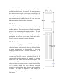
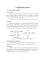
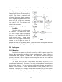
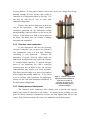
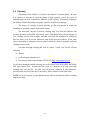
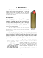
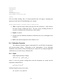
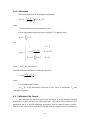
Gamma-2 Abyss Deep-Sea Transmissometer USER’S MANUAL Revision D H Hyyd drroo--O Op pttiiccss,, B Biioollooggyy & & IIn nssttrru um meen nttaattiioon n L Laabboorraattoorriieess Lighting the Way in Aquatic Science www.hobilabs.com [email protected] Revisions: D, March, 2011: Change “Abyss-2” to “Gamma-2 Abyss.” C, November 2010: Correct calibration formulas (section 6.4.2) B, May 2010: Extensive revision and additions. A, May 2010: Initial Release -2- 1 INTRODUCTION ................................................................................................................................. 4 1.1 1.2 1.3 2 QUICK START ..................................................................................................................................... 6 2.1 2.2 2.3 2.4 2.5 3 DESCRIPTION ................................................................................................................................... 14 CHARGING ....................................................................................................................................... 15 FIRMWARE COMMANDS............................................................................................................... 16 5.1 5.2 6 POWER AND DATA INTERFACE .......................................................................................................... 8 DATA SAMPLING AND LOGGING ........................................................................................................ 9 POWER-UP, SLEEP MODE AND SWITCH CONTROL ............................................................................. 9 DEPLOYMENT .................................................................................................................................. 11 CLEANING ....................................................................................................................................... 13 BATTERY PACK................................................................................................................................ 14 4.1 4.2 5 SETUP ................................................................................................................................................ 6 COLLECTING DATA ........................................................................................................................... 6 DOWNLOADING LOGGED DATA ......................................................................................................... 7 DISCONNECTING ................................................................................................................................ 7 SWITCH-ACTIVATED LOGGING .......................................................................................................... 7 OPERATIONAL DETAILS ................................................................................................................. 8 3.1 3.2 3.3 3.4 3.5 4 OPTO-ELECTRONIC DESIGN ............................................................................................................... 4 MECHANICS ....................................................................................................................................... 5 ELECTRONICS .................................................................................................................................... 5 PROTOCOL ....................................................................................................................................... 16 COMMON COMMANDS ..................................................................................................................... 16 DATA PROCESSING REFERENCE................................................................................................ 19 6.1 6.2 6.3 6.4 6.5 DATA FORMATS .............................................................................................................................. 19 .RAW FILE FORMAT ....................................................................................................................... 19 .DAT FILE FORMAT......................................................................................................................... 20 CALIBRATION FORMULAS................................................................................................................ 21 CALIBRATION FILE FORMAT ............................................................................................................ 22 -3- 1 INTRODUCTION The Gamma-2 Abyss is a dual-wavelength transmissometer that operates at ocean depths up to 6,000 meters. It is part of the HOBI Labs Gamma family of spectral transmissometers, which differ in depth ratings and number of wavelengths, but share many features. The Gammas use a folded optical path to keep all electronics in a single pressure housing, and to support multiple path length options up to a full meter (the standard path length is 30 cm). The optical path is completely open to natural water flow so no pumping is required, and the instrument contains no moving parts. The electronics include an intelligent controller with internal logging and large flash memory capacity. 1.1 Opto-electronic Design Figure 1 shows a schematic view of the beam optics. The two wavelengths are generated by separate LEDs. Each LED’s current is controlled through software, and modulated at a frequency and phase that allows it to be distinguished from the other. The LEDs’ beams pass through diffusers (not shown) and then a beam splitter that directs a portion of each to the output beam, and a portion to a reference photodiode. The reference photodiode and its associated preamplifier electronics are identical to those used to receive the signal after it passes through the water, except that the signal preamplifier has much higher gain. For both the reference and signal measurements, the signals from the two LEDs are separated from each other through digital synchronous detection. The source and receiver lenses have 100 mm focal lengths, and 1 mm pinholes at their focal planes make the beam divergence and receiver field of view less than 0.5º fullwidth in water. The beam exits the source window with a 5 mm diameter, and over a 1 m path expands to 14 mm. Figure 1. Optical Schematic -4- Note that ideal attenuation measurements require optics that completely reject all scattered light, regardless of how small the scattering angle. In practice, all transmissometers have finite acceptance angles, receive some scattered light, and therefore report attenuation values smaller than the theoretical value. Gamma-2 Abyss’s optics are closer to the ideal than most transmissometers, and therefore it will report somewhat higher attenuation values than those instruments. 1.2 Mechanics The Gamma-2 Abyss achieves its extreme depth rating through the use of titanium for the housing, and custom-made sapphire windows. The retroreflector is isolated from ambient pressure in its own housing with sapphire windows. The path length is determined by the standoff that attaches the retroreflector housing to the main housing. The standoff is machined in one piece to give it great strength and rigidity. Figure 2 shows the instrument’s outside dimensions. 1.3 Electronics A powerful logging computer, 128 MBytes (more upon request) of nonvolatile flash memory, and integration with a companion battery pack (section 4) allow the Gamma-2 Abyss to operate autonomously for deep profiling or long-term sampling, without real-time electrical connections to the surface. A high-resolution multi-channel digital-to-analog converter sets the LED currents under the control of the computer, allowing the current to be trimmed for optimum signal levels and balance between the wavelengths. The currents to the LEDs are modulated and synchronized with the analog-to-digital conversions so that the signals from the LEDs can be digitally isolated from each other and processed separately, even though they share detectors and preamplifier electronics. All signals are digitized at 1000 samples per second and digital filtering is applied to minimize noise in the final outputs. -5- Figure 2. Outside Dimensions 2 QUICK START 2.1 Setup Install HydroSoft on your computer. HydroSoft 2.80 or later is required. Connect the power/data interface (PDI) cable to the appropriate RS-232 serial port on your computer, or to a USB-Serial adapter. Connect the PDI’s underwater connector to the Gamma-2 Abyss. Run HydroSoft by selecting it on the Windows Start menu. Click Click the Search button. After a short time HydroSoft should identify the instrument, load its calibration, and close the Connect dialog box. Select Set Date/Time… from the Gamma-2 menu. Click Set Time to synchronize the Gamma-2 clock with your computer’s clock. This will take a few seconds. Then click Close to close the Date/Time dialog box. 2.2 (or select Connect from the Instrument Menu). Collecting Data Select Sampling Options… from the Gamma-2 menu. For testing purposes, we recommend the following settings: Sample Rate: 2 per second Start Delay: 0 seconds Burst mode: unchecked Select Plot Vs. Time from the Graph menu. (or select Start from the Gamma-2 menu). This will cause data to be Click logged in the flash memory as well as sent to HydroSoft. If no data are visible after a short time, click show all data. To adjust the way data are displayed, double-click on the graph, or select Properties… from the Graph menu. -6- , and the plot will zoom as needed to Click Close the open data file by selecting Close from the File menu, or clicking on the button. If desired, save the file when prompted. 2.3 (or select Stop from the Gamma-2 menu). Downloading Logged Data Select Get Data From Instrument from the Gamma-2 menu. After several seconds a directory of casts in memory will appear. The last cast listed should be the one you just recorded. If that cast is not already highlighted, click on it to highlight it, or click the Select All button. Click the Browse… button to select a directory in which to save downloaded data files. In the resulting dialog box, select a directory and click the Select button. If it is not already checked, check the Create calibrated data (.dat) files option. Click the Download button to begin transferring data casts. 2.4 Disconnecting After you are finished communicating with the Gamma-2, select Disconnect from the Gamma-2 menu. When asked “Put Gamma-2 to sleep before disconnecting?” click Yes. Unplug the PDI cable from the Gamma-2. 2.5 Switch-Activated Logging Note that the switch behavior can be modified with firmware commands. For details see section 3.3. To start a cast when the Gamma-2 is asleep and disconnected from the computer, move the switch on the end cap to the start position (in the direction of the arrows on the switch actuator). If the switch is already in the start position, first move it briefly to the opposite position. To end a cast, return the switch to the stop position. -7- 3 OPERATIONAL DETAILS 3.1 Power and Data Interface Power Supply The Gamma-2 requires a power source of 10 to 24 V at 1 to 1.5 W. The exact power consumption depends somewhat on the choice of wavelengths, since different LEDs have different efficiencies. With 470 nm and 532 nm channels, power is typically 1.2 to 1.3 W over the entire supply voltage range. In sleep mode (see section 3.3), current consumption is less than 100 µA at 12V. Connectors Data and power connections are through a SubConn BH4M connector (mating connector: IL4F). A BH2M connector (mate: IL2F) provides a second power input. Figure 3 shows the connector pin assignments. The power inputs on the two connectors are identical and protected against reverse voltage, so it is safe to connect separate power sources to them. Power will be drawn from the source that has the highest voltage. SubConn BH4M BH2M Figure 3. Connector pin diagrams (face view of male connectors) Power/Data Interface (PDI) Cable The optional PDI cable connects to the 4-pin connector and provides 4-way binding posts for power and a DB9F for connection to a computer’s RS232 port. Data interface Commands and data are transmitted via RS232 (8 bits, no parity, 1 stop bit). The default baud rate is 57600 baud, with standard rates from 2400 to 115200 supported. In HydroSoft, the baud rate can be changed from the Gamma-2 menu. See section 5 for information about commands, and Section 6 for data formats. -8- 3.2 Data Sampling and Logging Data are logged in flash memory according to parameters set with HydroSoft’s Sampling Options… command, or with the LOG firmware command (section 5.2.9). Data casts are started and ended either by software command or by the switch on the end cap (Figure 4). Depending on the LOG and switch settings, a data cast may also be started each time power is applied to the instrument. During casts, every sample saved in memory is simultaneously transmitted from the serial port. Individual samples can also be requested with the D firmware command (section 5.2.3). Samples requested this way are not logged. Averaging and Packet Timing Gamma-2 collects and averages data internally at 1000 Hz, and the values transmitted and logged are averages of these rapid samples. In general, a packet is an average of all the values collected since the previous packet, and until the moment the current packet is sent. In other words, if it is logging data once per second, the value reported at time X is actually the average of the value over the times from X–1 to X seconds. The time value reported in the packet is X, the end of the sampling interval. For sample periods up to 8 seconds, all the rapid samples are given equal weight in the average. For longer periods, older samples are given gradually decreasing weight. At the beginning of a data cast (started with the switch or START command), older samples are flushed from the average so that the first packet reported will include the same number of averaged samples as subsequent packets. 3.3 Power-up, Sleep Mode and Switch Control Gamma-2 provides various options to control its power mode and its response to the switch on its end cap (Figure 4). For most applications, there is no need to change from the default settings. 3.3.1 Default Setup The default configuration provides simple control of logging with the switch or with real-time control by HydroSoft. Setting the switch to “start” wakes the instrument, if it is asleep, and starts logging. Setting the switch to “stop” ends the current logging cast and puts the instrument into low-power sleep. To restore the default settings, send the commands SW,1,1,1 and LOG,,,0. To make the LOG settings permanent, also send STORELOG. -9- 3.3.2 Sleep-Wake Details In sleep mode, all activity is suspended and current consumption falls to about 100 µA. Sleep can be initiated either with the external switch or with the SLEEP command (see section 5.2.11). During sleep all settings and state information are maintained in battery-backed memory. If a logging cast is in progress at the time of sleep, it will resume upon the next wake (although if sleep is triggered by the switch, by default the cast will be stopped first). Figure 4. Switch location. The arrows on the switch actuator point toward the “start” position. Sleep is ended by moving the switch to the start position, by any activity on the serial port input, or by the real-time clock if a sleep time was specified with the SLEEP command. If power is removed while it is asleep, applying power again will only wake the instrument if the switch is in the start position (see Switch Details below) 3.3.3 Switch Details The behavior of the switch can be altered from the defaults described above with the SW firmware command (also see section 5.2.15). SW can independently set whether the switch starts casts, stops casts, and puts the instrument to sleep. However the switch will always wake the Gamma-2 from sleep. Note that, except at the time power is first applied, the switch only acts when moved from one position to the other, and its position can be overridden by software commands. For example, if the switch is in the stop position you can still start a data cast from HydroSoft or by sending the START command. If you move the switch to the start position while that cast is still in progress, it will have no effect, but moving it back to the stop position will stop the cast (if the StopsCasts parameter of the SW command has its default setting). The one case in which the switch can affect the instrument’s behavior without being moved from one position to the other is when power is first applied. If the switch is in the start position, applying power will always wake the instrument, and it will start a cast if the switch’s StartsCasts parameter is set to 1. 3.3.4 Power-up Behavior Figure 5 shows how the Gamma-2 reacts to the application of external power, depending on its various command options. When all options are set to their defaults, the - 10 - instrument will either boot into the “wait for commands” state, or, if was put to sleep before power was last removed, it will remain asleep. If it is not waking from sleep, the Gamma-2 will reboot each time power is applied. The reboot is completely safe and normal, but resets volatile parameters such as logging settings that have not been stored with the STORELOG command (see section 5.2.14). The real-time clock setting is always retained. 3.3.5 Using Power to Control Logging Note that while it is possible to use the Gamma-2 in a “dumb” mode where you initiate logging simply by applying power to it, you should not end casts by simply removing power. Cutting power Figure 5. Program flow when power is first while a cast is in progress will definitely applied. result in the loss of up to 30 seconds of buffered data from the cast, and in addition, creates the risk of damaging the entire flash file directory and losing all logged data completely. 3.4 Deployment 3.4.1 Mounting In order for the Gamma-2 to be safely lowered on a cable, it must be secured in a frame or other structure that provides a suitable attachment point. Figure 6 shows the recommended frame, supplied by HOBI Labs. The figure also shows a battery pack attached to the frame, which is required if the lowering cable does not have conductors for supplying power. The frame shown here has several features that make it very secure if it is assembled and used properly. It consists of two pairs of clamps that go around the main housing of the Gamma-2. The lower pair has a smaller inside diameter that matches the diameter of the Gamma-2’s “waist” and ensures that it cannot possibly slide off the instrument. The upper pair of clamps is rigidly connected to the lower pair with stainless steel rods so the clamp pairs provide mutual support. A forged stainless steel eye is threaded into the top of each rod, and it is to these four eyes that user can secure a - 11 - lowering harness. If using rope to attach to these eyes, do not use a single loop of rope threaded through all four, because that would be vulnerable to a single-point failure by the rope. Use one loop for each pair of eyes, or some other redundant arrangement. Figure 6 also shows a clamp pair on the lower end of the instrument. This simply provides convenient protection for the instrument housing during handling, especially when it is laid on its side on deck. It also allows it to stand on end as shown in the figure, but never leave the Gamma-2 standing unsecured and unattended. 3.4.2 Real-time cable connection If your deployment cable has the necessary electrical conductors, you can power the Gamma-2 and communicate with it in real time, including controlling it with HydroSoft. However the limitations of typical electrical cables make this impractical for applications that exploit the Gamma2’s extended depth capability. To provide adequate power to the instrument, the cable’s round-trip resistance must be 100 ohms or less, and real-time communication may require even lower resistance. This limits practical cables to at most a few hundred meters length and possibly much less. If you intend to use a real-time cable connection for deployment, always test the cable and instrument beforehand, in the deployment configuration. 3.4.3 Battery-powered deployment Figure 6. Gamma-2 Abyss with deployment frame and battery pack (also see section 4). Warning: do not leave the instrument standing this way without securing it! The Gamma-2 works seamlessly with a battery pack to provide data logging without any electrical connection to the surface. For battery-power profiling you can leave the battery connected continuously and start and stop logging with the end cap switch. Each switch-activation will create a new numbered cast in flash memory. - 12 - 3.5 Cleaning Cleanliness of the windows is critical to the Gamma-2’s measurements. Because it is sensitive to fractions of a percent change in light intensity, even a tiny speck of contamination can make a significant difference in the readings. Fortunately cleaning is not difficult, and the instrument’s sapphire windows are difficult to damage. The degree of cleaning required depends on the environment in which the instrument is operating, and the deployment routine. The most basic, but one of the best, cleaning steps is to rinse the windows with generous quantities of distilled or deionized water. This should always be the last step in your cleaning process, and is highly advisable each time the instrument is withdrawn from the water, so as to prevent substances from drying onto the windows. If the water you are measuring is among the clearest natural waters, this alone is probably sufficient cleaning between casts. For more thorough cleaning and work in “dirtier” waters, you can use solvents including ethanol, weak detergent solutions, and lens cleaners (such as part number NT54828 at http://edmundoptics.com). For the most thorough possible cleaning, use each of these in the order listed, and follow with a pure-water rinse. In relatively clear water it is adequate to do such a thorough cleaning only once per day. In water rich with growth, sediment, or oily substances, more frequent use of solvents may be necessary, always followed with clean water. NOTE: do not use acetone or other harsh solvents, which can attack the plastic retaining rings and o-rings. - 13 - 4 BATTERY PACK The Abyss battery pack is an ideal companion for the Gamma-2 Abyss in deep profiling applications. It matches the Gamma-2 Abyss’s 6000 meter depth rating and has enough rechargeable capacity to power the Gamma-2 for at least 24 hours of continuous data collection. 4.1 Description The battery pack case is 8.7 cm (3.45”) in diameter, 24.3 cm (9.55”) long, and is made of hard-anodized 7075 aluminum. The anodizing and a zinc anode on the connector end cap protect against corrosion in water as long as there is no electrical contact between the case and other metals. Plastic mounting brackets such as those supplied by HOBI Labs (see Figure 6) ensure proper insulation. The pack includes a pressure relief valve to prevent hazardous buildup of gas that could result from (rare) faults in the batteries or charger. Figure 7. Abyss Battery Pack The battery pack has a nominal voltage of 10.8, with the actual voltage ranging up to 13 V when fully charged, depending on temperature. HydroSoft displays the voltage whenever the instrument is connected and logging (but remember that if voltage is being supplied by another source, only the higher voltage is displayed). The battery is roughly 90% discharged when its voltage declines to 10 V. Its total capacity is 3 A-hr, enough to power the Gamma-2 continuously for well over 24 hours. Figure 8. Battery pack connector wiring. SubConn BH4F connector, face view. Mating connector is IL4M. The output is protected against heavy overload by a positive temperature coefficient thermistor (“resettable fuse”) that reduces the output voltage if the current goes above about 3 A. Once tripped, the thermistor will keep the current low (but not zero) until the load is disconnected long enough for the thermistor to cool. - 14 - 4.2 Charging Charge the pack only with the HOBI-supplied charger. Plug the charger into the battery pack before connecting the AC input to the charger, and after disconnecting the AC input. This prevents shorting the exposed pins on the charger’s adapter cable while power is applied. Do not charge the battery too frequently. Note that the charger replaces charge 10 to 20 times as fast as the Gamma-2 consumes it. - 15 - 5 FIRMWARE COMMANDS The Gamma-2 is configured and controlled with commands sent via its serial communication port. When you use HydroSoft, the commands needed for routine operation are generated automatically and you do not need to know the details. However you can type commands manually and view the instrument’s replies directly, via HydroSoft’s terminal window or a generic terminal program. 5.1 Protocol The Gamma-2 communicates through a standard RS-232 serial connection, with 8 data bits, no parity, one stop bit, and no handshaking. The default baud rate is 57600, but it can be set to other standard rates from 2400 to 115200 through HydroSoft or the BAUD command described below. The Gamma-2 waits until it receives a carriage return and/or line feed before responding to a command. When it is not actively logging data, it retransmits each character it receives. Character echo is disabled during logging, so that commands can be sent without affecting the output data stream. Commands are case-insensitive. They are shown below in upper case for clarity. Some commands accept arguments, which are separated from the base command, and from each other, by commas or spaces. Arguments may be individually omitted if commas are used as placeholders for them. For example, if a command accepts three arguments, in the form COMMAND,arg1,arg2,arg3, you may adjust only arg3 by entering COMMAND,,,arg3. 5.2 Common Commands 5.2.1 BAUD newrate Reports the current baud rate of the instrument. If a valid newRate is specified (2400, 4800, 9600, 19200, 38400, 57600 or 115200), the rate will immediately change. Note that, because of the time required to transmit data packets, lower baud rates may limit the maximum sampling rate. 5.2.2 CLEARLOG Deletes all cast files from flash memory, and resets the cast number to 1. Because this will result in permanent loss of data, the firmware asks for confirmation before proceeding. Deleting large and numerous files can take up to several minutes. - 16 - 5.2.3 D Sends a packet with the most recently collected data. 5.2.4 DATAFORMAT formatNumber Sets the format of packets that will be sent during logging, cast downloads, and in response to the D command. As of firmware 1.00, formatNumber can either be 0 to indicate a “brief” packet or 1 to indicate a “full” packet (see section 6.1 for details). 5.2.5 DELCAST castNumber Deletes the given cast (does not prompt for confirmation). Does not affect the current cast counter. 5.2.6 DIR Displays a directory of the casts in flash memory, including their start times, durations and number of samples. 5.2.7 DOWNLOAD castNumber Sends the data from the given castNumber, if any, from the Gamma-2 in the current data format. 5.2.8 ID Displays identifying information about the instrument and its configuration. This is automatically used by HydroSoft when it connects to an instrument. 5.2.9 LOG period delay startOnPower Displays the current logging settings, and changes them if valid values are provided. Period is the number of seconds between samples (which has a minimum value of 0.1). Delay is the number of seconds the first sample will be delayed after logging is initiated (not implemented in firmware version 1.00). StartOnPower controls whether logging will start when power is first applied to the instrument. Note that startOnPower may be overridden by the start/stop switch, depending on its setup. See section 3.2 for switch details. Changes you make to the LOG parameters will not be retained when power is removed from the instrument, unless you use the STORELOG command to make them permanent. 5.2.10 SENDCAL Sends the entire contents of the instrument’s internal cal file, if any, through the serial port. - 17 - 5.2.11 SLEEP seconds Sends the instrument into its low-power sleep mode. Logging and any other activities are stopped during sleep. If seconds is specified, the sleep will end after that time interval has passed. Otherwise it will sleep until woken by the switch or serial port activity. 5.2.12 START Starts logging with the current log settings, using the next sequential cast number. 5.2.13 STOP Stops the current logging cast, if any. 5.2.14 STORELOG Stores the parameters of the LOG command in nonvolatile memory 5.2.15 SW StartsCast StopsCast Sleeps Displays the current switch parameters, and changes them if valid values are supplied. Nonzero StartsCast means that moving the switch from off to on will start logging (as if the START command were issued). Nonzero StopsCast means moving the switch from on to off will stop logging (as with STOP). Nonzero Sleeps means moving the switch from off to on will put the instrument into an indefinite sleep (as with the SLEEP command). The default setting is 1 for all three parameters. For more about the switch, see section 3.2. 5.2.16 VER Displays the installed firmware version. 5.2.17 VIN Displays the input supply voltage to the instrument. If voltages are applied to both connectors, only the higher one is reported. The voltage reported will be slightly lower than the actual applied to the connector, because it is measured after the voltage passes through a protection diode. This is the same voltage that is reported in full data packets. - 18 - 6 DATA PROCESSING REFERENCE 6.1 Data Formats Data are transmitted in raw comma-separated decimal ASCII, with the following parameters: time,signal1,signal2,reference1,reference2,pressure,temp1,temp2,temp3,Vin,bgnd,smin, smax, rmin, rmax, N Time is in seconds since midnight Jan 1, 1970, sometimes called “UNIX time.” Signal1 and signal2 are raw digital counts measured by the signal detector from the two optical channels. Reference1 and Reference2 are the signals measured by the reference detector before the beam enters the water. Pressure is the raw digital reading of the pressure transducer. Temp1, temp2 and temp3 are temperatures measured at three different places within the instrument (not water temperature). The reported values are 100 times the actual temperature in C. Vin is the supply voltage input. Its value is 100 times the actual voltage. Bgnd, Smin, Smax, Rmin and Rmax are state-of-health indicators showing the signal levels at different parts of the circuitry. N is the number of samples averaged to produce the packet. Normally this will be 1000 times the sample period in seconds. If you use the DATAFORMAT command to set the data format to 0, a briefer version of the above is produced, which is identical except that it ends after temp3. The brief packets are sufficient for producing calibrated data, so you can speed downloads of large data files by selecting this format. The default DATAFORMAT setting is 1, producing the full packet shown above. 6.2 .RAW File Format HydroSoft’s .raw files start with a header similar to the following, but the exact contents or sequence of the header are not guaranteed to remain the same in all versions of HydroSoft. - 19 - [Header] HydroSoftVersion=2.80 CreationDate=04/10/10 14:49:43 FileType=raw DeviceType=Gamma-2 DataSource=G2100100 CalSource=Gamma-2 Serial=G2100100 Config=100 [EndHeader] Following the header is a complete record of every byte received from the instrument. This will include data packets but may include other informational messages. In the following example, the “START” command sent by HydroSoft is echoed by the instrument, which also announces the start and end of the cast: START Starting cast 6 in 2 seconds. 1274885398.44,1,2,0,0,5588,-1938,-2278,2325,1117,12511,-23402,22826,-22015,-21489,504 1274885398.94,1,3,-1,1,5601,-1933,-2273,2325,1117,12511,-23404,22827,-22014,-21483,500 1274885401.94,0,-1,-1,0,5592,-1936,-2277,2326,1117,12513,-23399,22794,-22012,-21487,500 Stopped cast 6. 6.3 .DAT File Format HydroSoft .dat files start with a header similar to the following. As with the raw header, the exact contents and format are not guaranteed, but the [Channels] and [ColumnHeadings] heading will remain the same. The [Channels] heading announces the names of the primary optical data from the instrument, as displayed in the legends of HydroSoft’s graphs, listed one per line. The line following [ColumnHeadings] is a comma-separated list of the names of the parameters listed in the data lines. [Header] HydroSoftVersion=2.81 CreationDate=04/10/10 14:49:43 FileType=dat DeviceType=Gamma-2 DataSource=Gamma-2 CalSource=Gamma-2 Serial=G2100100 - 20 - Config=100 [Channels] "c470" "c532" [ColumnHeadings] Time,Depth,c470,c532,IntT [Data] After the [Data] heading, lines of comma-separated data will appear, containing the parameters listed under [ColumnHeadings], for example: 40324.6180722222,2.38790,0.1032,0.2018,22.83 Time is expressed as the number days since the start of January 1, 1900, which is the native format of Microsoft Excel. The time of day, including fractions of seconds, is included in the fractional part of this number. Depth is in meters. c1 and c2 are the calibrated attenuation coefficients at the two wavelengths of the Gamma-2. IntT is the internal temperature of the Gamma-2, in C. 6.4 Calibration Formulas The calibration formulas support compensation for several kinds of temperature and pressure-related effects. Depending on the characteristics of the individual instrument, some portions of the processing may be “turned off” by setting the applicable coefficients to zero in the factory calibration file. 6.4.1 Depth Offset-adjusted pressure reading: P(T ) P P0 p(T ) p(TP 0 ) where P is the raw pressure reading direct from the instrument (in counts) and the temperature-related offset is p(T ) k p1T k p2 T 2 Calibrated depth in meters of sea water: D k D1 P(T ) kD 2 P(T ) 2 - 21 - 6.4.2 Attenuation Transmission adjusted for temperature and pressure: S S0 aT (T )aP (P) R R0 (T , P) where T is the instrument’s internal temperature in C, P is the temperature-adjusted pressure reading P(T) in digital counts, 5 aT (T ) kTn T , n 0 and 1, 1 k (P P1 ) , PX P2 P1 aP (P) 5 1 k PX k Pn P, n 0 P P1 P1 P P2 P P2 where P1 and P2 are values of P(T). The fully calibrated attenuation coefficient is given by (TPW , 0) 1 c ln (T , P) L where L is the path length in meters (TPW , 0) is the transmission measured in pure water, at temperature Tpw and atmospheric pressure. 6.5 Calibration File Format The calibration file, whether stored in the instrument or on the computer running HydroSoft, is a plain text file in the following format. The sequence of parameters is not guaranteed, and it is possible additional parameters could be added in future versions. Therefore any software that reads the file should identify parameters by their labels, not - 22 - their sequence. Table 1 shows the plain-text names used in the calibration file for the terms in the formulas above. Any line in the calibration file may also include a comment after the parameter value, marked with a double-slash (//). [General] DeviceType=Gamma-2 // Saved by HydroSoft 2.80 Serial=C2100000 Label=HOBI Config=100 MaxDepth=6000 CalTime= 1270080000 (04/01/10) [Depth] kp1=10.215 kp2=-0.1624 P0=1439 TP0=26.68 kD1=0.3619 kD2=0 [Attenuation 1] Name=c470 Lambda=470 DeltaLambda=10 L=1.005 S0=-3 R0=0 kT0=0.9926 kT1=0.0031851 kT2=-0.0002447 kT3=4.8421e-6 kT4=0 kT5=0 P1=50 P2=103 kTauPX=0.1188 kTauP0=.66 kTauP1=1.0771e-5 kTauP2=-7.6957e-10 kTauP3=1.1615e-14 kTauP4=0 kTauP5=0 Tau0=1.00167 TPW=20.77 [Attenuation 2] <Same format as Attenuation 1> [End] - 23 - Table 1. Parameters as Named in the Calibration File Term kp1, kp2 P0 TP0 kD1, kD2 L S0 R0 kT0…kT5 P 1, P 2 Name in Cal File kp1, kp2 P0 TP0 kD1, kD2 L S0 R0 kT0…kT5 P1, P2 kTauPX Description Coefficients for temperature-related change in pressure offset Raw pressure reading at atmospheric pressure and temperature TP0. Temperature at which P0 was measured. Coefficientss for conversion of digital counts to meters of sea water. Path length in meters Raw signal with path blocked Raw reference with LED disabled Transmission temperature coefficients Pressure thresholds, in temperature adjusted counts, for aP(P) Coefficient of linear pressure correction aP(P) kP0… kP5 Coefficientss for polynomial pressure correction in aP(P) 0 kTauP0…kTouP 5 Tau0 TPW TPW k PX Temperature-compensated transmission in pure water, at atmospheric pressure. Temperature at which 0 measured. - 24 -