1
Creating Subcircuits and Hierarchical Blocks in LTspice
Mike Kelsch
January 2007
This tutorial gives some techniques for creating Subcircuits and Hierarchical Blocks
using LTspice /SwitcherCAD III Version 2.19p (available free from Linear Technology
at: http://www.linear.com/company/software.jsp).
Subcircuits:
Subcircuits allow the designer to create a model or circuit for a device that may be used
many times in a schematic (and saved for later use in other circuits). Each instance of the
device can use the same “parameters” (values) or the parameters can be changed on an
instance-by-instance basis. The advantage of a subcircuit is that one symbol on a
schematic can represent another circuit. Whenever that symbol is placed on the
schematic, the entire subcircuit is placed. This allows for ease of design with more clarity
on the schematic.
Procedure:
1) Create a netlilst using a text editor such as notepad.
a) use the .subckt statement followed by the name of the subcircuit followed by the
pins (e.g. .subckt myopamp 1 2 3) (see example). The numbers will be used as
node numbers for connection to other components (0 is ground). The order of the
numbers will be the order used for the “pin/port netlist order” on the symbol.
b) End the subcircuit with the .ends statement (e.g. .ends myopamp).
c) Save the netlist as filename.lib or filename.sub, the name does not have to be the
same as the name of the subcircuit (in fact, more than one subcircuit can be
included in a .lib or .sub file. See “Notes on Saving”
2) Draw a symbol to represent the device.
a) Select File Æ New Symbol, to open the Symbol Editor.
b) Draw the symbol using the Draw menu and the Line, Rect, Circle, etc. commands.
c) Place the pins. Select Edit ÆAdd Pin/Port to get the Pin/Port Properties dialog
box. At the top right is the Netlist Order box. This order corresponds to the order
of the pins in the subciruit. A label can be inserted using the Label box (e.g. Vin),
but has nothing to do with the function of the pin. The pin's function relates to the
connection specified in the subcircuit netlist. To make the label visible select one
of the Pin Label Position buttons.
d) Some information, such as, Instance Name can be added by selecting Edit
ÆAttributes Æ Attribute Window and selecting the information. Clicking OK
will allow pasting on the symbol
1
Creating Subcircuits and Hierarchical Blocks in LTspice
3) Open the Symbol Attribute Editor to enter the appropriate information.
a) Select Edit ÆAttributes Æ Edit Attributes.
i) Select Cell in the Symbol Type drop-down box.
ii) Select Prefix, type X in the Prefix = box. X tells LTspice that this is a
subcircuit.
iii) In the Value field type the name of the .subckt (e.g. myopamp)
iv) SPICELine can be used to pass parameters.
v) Leave ModelFile blank.
b) Save the symbol, File Æ Save As saves the file as a *.asy. See “Notes on Saving”
4) On the schematic, include a SPICE Directive with the path of the subcircuit file (e.g.
.lib C:\Program Files\LTC\SwCADIII\My Work\OpampExample.lib).
Here is an example of an ideal op-amp subcircuit:
Step 1.
Create a subcircuit netlist using a text editor.
*Ideal Op-Amp
*
V.subckt myopamp 1
g1 3 0 2 1 100Meg
.ends myopamp
V+
2
“*” means this is a comment
This line is for clarity only
Subcircuit named myopamp with three pins
Dependent source with nodes and gain
End of the subcircuit
Out
3
Save As ÆOpampExample.lib (in this example the full path is:
C:\Program Files\LTC\SwCADIII\My Work\OpampExample.lib)
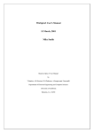
This is what a schematic of the subcircuit
would look like. “g1” is a linear voltage
controlled current source with pins of
<+node><-node><+controlling node>
<-controlling node><gain>. Now when the
symbol is made the “netlist order” of the
pins will be Inverting Input (pin 1), NonInverting Input (pin 2), Output (pin 3).
2
Creating Subcircuits and Hierarchical Blocks in LTspice
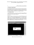
Step 2.
The Inverting pin is on top and has a
“netlist order” of 1. The Output is pin 3.
Unnn was created by Edit ÆAttributes Æ
Attribute Window and selecting InstName.
This will appear as U1, U2, etc on the
schematic.
Pin1
Pin3
Pin2
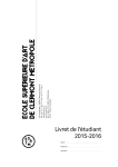
Step 3.
Select Edit ÆAttributes Æ
Edit Attributes.
Symbol Type Æ Cell
Prefix Æ X
Value Æ myopamp
The name of the subcircuit,
“myopamp,” is placed in
the Value field. This is the
name that follows the
.subckt statement in the
netlist, not the name of the
file.
File Æ Save As Æ
myopamp.asy
3
Creating Subcircuits and Hierarchical Blocks in LTspice
Step 4.
.lib statement tells
LTSPICE where to find the
file “OpampExample.lib”
which contains the
subcircuit “myopamp.”
Notes:
Right clicking on U1 will bring up the Component Attribute Editor. Here information can
be made visible on the schematic by selecting the desired line and checking the Visible
box. Notice an x is shown in the V column indicating the instance name (U1) will be
visible on the schematic. This editor will also allow changes to the attributes listed. The
path of the device symbol is shown to the right of the Open Symbol button.
Selecting the Open Symbol button opens the symbol for the device. With the symbol
opened the Edit Æ Attributes commands can be used in the same manner described in
steps 2d and 3.
4
Creating Subcircuits and Hierarchical Blocks in LTspice
The open symbol can be edited using the
Edit Æ Attributes commands.
Hierarchical Blocks:
Creating Hierarchical Blocks is similar to using a subcircuit in that a symbol can
represent another circuit in a schematic. The hierarchical block is a schematic that is
represented on a higher-level schematic by a symbol. In the example on subcircuits, a
netlist represented an op-amp then a symbol representing that subcircuit was placed on
the schematic. For a hierarchical block, a schematic is created to model the op-amp and a
symbol is made to represent the schematic of the op-amp. The op-amp’s schematic is a
lower-level schematic. Selecting the symbol on the higher-level schematic allows
viewing of the lower-level circuitry. Once open the voltages and currents can be probed
just as in the higher-level schematic.
Procedure:
1) Create a schematic of the device to be represented by a block.
a) Use LTspice’s schematic capture to draw the circuit. If semiconductor models or
subcircuits are used, add a .lib directive with the path and name of the file.
b) Label any nodes that will be connected to the higher-level circuit. Select Edit Æ
Label Net. In the box next to ABC type a name or number. Port Type select None
(or as desired).
c) Save the schematic as a *.asc file (e.g. oaBlock.asc). This can be saved in a
working directory. “Notes on Saving”
2) Create a symbol to represent the lower level schematic.
a) Select File Æ New Symbol, to open the symbol editor.
b) Draw the symbol using the Draw menu and the Line, Rect, Circle, etc. commands.
c) Place the pins. Select Edit ÆAdd Pin/Port to get the Pin/Port Properties dialog
box. At the top right is the Netlist Order box. The Netlist Order is not crucial but
the Label box (left of the Netlist Order box) is very important. The Label box
must match the Net labels from step 1b. To make the label visible select one of
the Pin Label Position buttons (if desired).
d) Some information, such as, Instance Name can be added by selecting Edit
ÆAttributes Æ Attribute Window and selecting the information. Clicking OK
will allow pasting on the symbol.
5
Creating Subcircuits and Hierarchical Blocks in LTspice
3) Open the Symbol Attribute Editor. Select Edit ÆAttributes Æ Edit Attributes. Select
Block from the Symbol Type drop-down box. Leave all attributes blank. Save the
symbol, File Æ Save As saves the file as a *.asy. See “Notes on Saving”
4) Now the component can be placed in a new schematic.
Here is an example of an ideal op-amp using a hierarchical block:
Step 1.
Schematic created using “g” from the
symbol library using the Select
Component Symbol dialog box (Edit Æ
Component).
Nodes Labeled using Edit Æ Label Net.
Numbers or names can be used.
File Æ Save As oaBlock.asc
Step 2.
A new symbol can be created or a
previously created symbol can be used.
Here myopamp.asy from the previous
example is used.
In the Label box of the Pin/Port
Properties dialog box enter the label
that matches the schematic
oaBlock.asc.
If making a new symbol from scratch
use
Edit Æ Add Pin/Port.
If using a previously created symbol
Right Click on the pin to get the
Pin/Port Properties box.
Here the pin labels are visible, this is
optional.
6
Creating Subcircuits and Hierarchical Blocks in LTspice
Step 3.
Select Edit ÆAttributes Æ Edit
Attributes. Select Block from the
Symbol Type drop-down box. Leave
all attributes blank. Save the symbol
File Æ Save As oaBlock.asy
Insert the component in the schematic.
The displayed name was X1. Change
its name (if desired) by placing the
cursor over the label, Right Clicking
and replacing X1 with op_amp.
Notes:
Right clicking on the component brings up the Navigate/Edit Schematic Block dialog
box. The Symbol or its Schematic can then be opened. If the lower level schematic is
opened it’s symbol can be opened from the Hierarchy menu.
7
Creating Subcircuits and Hierarchical Blocks in LTspice
Passing Parameters:
Curley Brackets {} and the .param statement can be used to pass parameters to
components.
Curley brackets enable the use of variables. The .param statement can be used to specify
values for the variables. For example:
.subckt V_opamp 1 2 3
ro 3 0 {Rout}
co 3 0 {Cout}
e1 3 0 1 2 {Ao}
.param Cout={1/2/pi/fo/Rout}
.param Ao={-A}
.ends V_opamp
Here variables are set using a combination of curly brackets and .param statements. This
allows the use of one subcircuit with parameters being changed on the schematic, using
the Component Attribute Editor, instead of in the netlist. Right Clicking the component
can access the editor. To use this method add the variable names and values to the
SpiceLine and SpiceLine2 values (e.g. A=100meg) when first creating a symbol (see
number 3 of the subcircuit procedure). Alternatively, for an existing symbol use the
Component Attribute Editor. Each instance of a component can have different
parameters through use of the Component Attribute Editor. A .param statement can also
be placed on a schematic as a SPICE Directive.
Model Statements:
Some devices, such as, transistors and diodes require information on the device in order
to make calculations. A .model statement tells LTspice what parameters to use for
modeling semiconductors. However, LTspice uses default models even if a model file is
included. To use models other than the default select Tools Æ Control Panel Æ Netlist
Options tab and uncheck the Semiconductor Models boxes. Remember to use a .lib or
.include directive to include the path of the model file (e.g. .lib C:\Program
Files\LTC\SwCADIII\My Work\CMOS.lib).
8
Creating Subcircuits and Hierarchical Blocks in LTspice
Uncheck the Semiconductor
Models boxes when not using
LTspice default models.
When not using default models
a .model statement must be
included on the schematic with
the path and name of the
model file (e.g. .lib
C:\Program
Files\LTC\SwCADIII\My
Work\CMOS.lib).
Notes on Saving:
LTspice searches for the needed files as specified in the .lib or .include statement that is
placed on the schematic or in a netlist. If no statement exists, LTspice looks in the
SwCDIII\lib\cmp, SwCDIII\lib\sub, or the path of the schematic. It is recommended to
always use the .lib or .include directive to avoid error messages. Here are a couple of
techniques that might avoid headaches later.
1) Make a working directory in the SwCADIII folder (e.g. C:\Program
Files\LTC\SwCADIII\My Work). Save all your schematics in this directory.
2) Make a directory in the C:\Program Files\LTC\SwCADIII\lib\sym directory to
save all newly created symbols. This allows selection of a device from the Select
Component Symbol dialog box by locating the directory and selecting from the
list. Now custom components can be kept separately from Linear Technology’s
library of symbols. Creating a directory called MyLib (C:\Program
Files\LTC\SwCADIII\lib\sym\MyLib) is shown. Double clicking on MyLib opens
the new directory and lists the available symbols.
9
Creating Subcircuits and Hierarchical Blocks in LTspice
A directory called “MyLib” was
created in the C:\Program
Files\LTC\SwCADIII\lib\sym
directory. Closing and restarting
LTspice then opening the Select
Component Symbol dialog box
(Edit Æ Component) shows the
directory. Double clicking on the
directory opens it. Save all
symbols (*.asy files) in this
directory and they will now be
available. Each time a new
symbol is saves, close and restart
LTspice.
Setting User Preferences:
Color preferences for background, schematic components and text, and plots can be
changed using the Color Palette Editor. Select Tools Æ Color Preferences. To eliminate
the saving of files generated during simulations (.raw .log files etc.), select Tools Æ
Control Panel ÆOperations Tab and select yes to Automatically Delete…. Schematic
font sizes can be found on the Control Panel Æ Drafting Options Tab. Also on the
Drafting Options Tab is the Hot Keys Button. This screen allows for customizing
Keyboard shortcuts for commonly performed tasks. The SPICE Netlist and Error Log can
be accessed from the View menu and come in handy during troubleshooting. A Netlist
can be exported as a .net file using Tools Æ Export Netlist.
I hope this information is useful. To leave comments: [email protected]
Mike Kelsch
Additional information is available from the following:
LTspice user’s manual http://ltspice.linear.com/software/scad3.pdf
LTspice user’s group http://tech.groups.yahoo.com/group/LTspice/
Linear Technology http://www.linear.com/
10
Creating Subcircuits and Hierarchical Blocks in LTspice
Works Cited
Sennewald, Helmut 2006 Third Party Models
http://tech.groups.yahoo.com/group/LTspice/
Tront, Joseph G. 2004 Pspice for Basic Circuit Analysis New York: McGraw Hill
LTspice Users Manual
http://ltspice.linear.com/software/scad3.pdf
Winspice Tutorial
11
Creating Subcircuits and Hierarchical Blocks in LTspice
Glossary
Device: A circuit component. This could simply be a resistor or a complex circuit (e.g an
op-amp) which is represented on the schematic by a symbol.
Instance: each time a component or device is placed on a schematic, it is called an
instance of that device. For example if a circuit contains three Op-amps, each individual
op-amp is an “instance” of that op-amp. Each instance is identified by a letter
representing the type of component (e.g. R for resistor) followed by a unique number.
Instance numbers can be changed and can contain numbers and or letters as long as no
two instances have the same label. Instances can have different parameters (values).
Netlist: A text file representing a circuit. LT Spice recognizes files ending in “.cir .net,
and .sp” as netlists. The first line of a netlist is taken to be a comment, so begin all netlists
with a comment. End a netlist with the “.end” statement. WinSPICE uses filename.cir
and PSPICE uses filename.net.
Parameters: Values for a device or used for calculating the values for the device.
Parameters can be assigned by use of a .param statement or by use of curly brackets{ } in
a subcircuit.
SPICE Directive: A command telling a SPICE program to perform an operation. SPICE
directives can be included in netlists (as for a subcircuit) or placed on the schematic.
These directives begin with a period. Some examples: .lib, .include, .subckt, .model,
.tran. Place a SPICE directive using Edit Æ SPICE Directive or use the “.op” icon.
Symbol: A user created drawing used to represent a device. The device could be
described by a subcircuit or a hierarchical block. To make a symbol select File Æ New
Symbol. Then use the Draw menu to add shapes and text. The shapes have no electrical
connection. The electrical connection is established by placing pin/ports using the Edit Æ
Add Pin/Port command.