Transcript
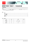
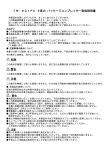
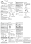
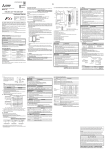
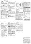
JY997D60101C Side A JAPANESE Side ENGLISH Side CHINESE A B C MELSEC iQ-F FX5-422-BD-GOT ハードウェアマニュアル マニュアル番号 JY997D60101 副番 C 作成日付 2015年4月 このたびは,本製品をお買い上げいただき,誠にありがとうございました。 本マニュアルは,本製品の各部名称,外形寸法,取付け, および仕様について述べ たものです。 本製品の取り扱いや操作などにつきましてはご使用の前に,本マ ニュアルおよび関連製品マニュアルをお読みいただき,機器の知識や安全の情 報,注意事項のすべてについて習熟してからご使用ください。 また, 製品に付属しているマニュアルは必要なときに取り出して読めるように大 切に保管すると共に,必ず最終ユーザまでお届け頂きますようにお願いいたしま す。 商標について: 会社名,製品名称は,それぞれの会社の商標または登録商標です。 この印刷物は2015年4月の発行です。なお,お断りなしに仕様を変更することがあ りますのでご了承ください。 2014 MITSUBISHI ELECTRIC CORPORATION 安全上のご注意 (ご使用の前に必ずお読みください) 本マニュアルでは,安全注意事項のランクを ます。 対応規格 FX5-422-BD-GOTは,EC指令(EMC指令)に対応しています。 詳細については,下記マニュアルを参照してください。 →MELSEC iQ-F FX5Uユーザーズマニュアル(ハードウェア編) CPU ユニットの規格対応については,総合カタログをご参照頂きますか,別途弊社まで お問い合わせください。 取付け上の注意 FX5-422-BD-GOT 形 RS-422 通信用拡張ボードは,MINI-DIN 8pin コネクタで GOT と接続 し, RS-422通信を行う拡張ボードです。 製品の導電部には直接触らないでください。誤動作,故障の原因となります。 1.1 同梱品の確認 製品本体 FX5-422-BD-GOT形RS-422通信用拡張ボード 付属品 拡張ボード取付け用タッピンネジ(M3×8) :2個 ハードウェアマニュアル(本書) 1.2 外形寸法・各部名称 単位:mm [6] [3] 注意 コネクタカバーを 取外した状態 [5] 38 質量:約20g 外装色:マンセルN1.5 15.4 [1]RS-422機器接続用コネクタ (MINI-DIN 8pin メス) [4]RD LED (緑色) :データ受信時点灯 [2]取付け穴(2-3.2) [6]CPUユニット接続用コネクタ FX5U CPU ユニットの入出力仕様,配 線,取付け, 保守などのハードウェア に関する詳細説明 非絶縁(通信ラインとCPU間) 通信方式 半二重双方向 通信速度 9600/19200/38400/57600/115200 (bps) ※1 最大伝送距離は,各接続機種のマニュアルを参照してください。 ネジ穴加工や配線工事を行うときに,切粉や電線 をシーケンサの通風孔へ落と し込まないでください。火災,故障,誤動作の原因となります。 拡張ボードや拡張アダプタは,所定のコネクタに確実に装着してください。接触 不良により誤動作の原因となることがあります。 拡張ボードは,必ず固定用タッピンネジで,固定してください。締付トルクは,マ ニュアルに記載したトルクに従ってください。規定範囲外のトルクで締め付けた 場合,接触不良により誤動作の原因となることがあります。 取付けなどドライバにより行うときは,慎重に行ってください。製品損傷や事故 の原因になります。 取付けの詳細については,下記マニュアルを参照してください。 →MELSEC iQ-F FX5Uユーザーズマニュアル(ハードウェア編) 注意 立上げ・保守時の注意 分解,改造はしないでください。故障,誤動作,火災の原因となることがあります。 * 修理については,三菱電機システムサービス株式会社にお問い合わせください。 本品を落下させたり,強い衝撃を与えないでください。破損の原因になります。 注意 廃棄時の注意 注意 輸送時の注意 本品は精密機器のため,輸送の間は専用の梱包箱や振動防止用パレットを使用す るなどして一般仕様の値を超える衝撃を避けてください。 本品の故障の原因になることがあります。輸送後,本品の動作確認および取付部 などの破損確認を行ってください。 JY997D54201 絶縁 製品を廃棄するときは,産業廃棄物として扱ってください。 関連マニュアル MELSEC iQ-F FX5U ユーザーズマニュアル (ハードウェア編) MINI-DIN 8pin(メス) 注意 [3]コネクタカバー 関連マニュアルとマニュアルの入手方法 内容 GOTの仕様による 外部機器接続方法 [5]SD LED(緑色) :データ送信時点灯 があります。いずれも重要な内容を記載していますので,必ず守ってください。 マニュアル番号 最大伝送距離※1 3. 仕様 なお, 注意 に記載した事項でも, 状況によっては重大な結果に結びつく可能性 マニュアル名称 仕様 RS-422規格準拠 [4] [1] 取り扱いを誤った場合に, 危険な状況が起こりえて, 中程度の 傷害や軽傷を受ける可能性が想定される場合,および物的損害 だけの発生が想定される場合。 警告 取付け上の注意 1. 製品概要 警告 , 注意 として区分してあり 取り扱いを誤った場合に, 危険な状況が起こりえて, 死亡また は重傷を受ける可能性が想定される場合。 項目 EU域内販売責任者は下記のとおりです。 EU域内販売責任者: Mitsubishi Electric Europe B.V. 住所: Gothaer Str.8,40880 Ratingen,Germany 注意 本製品は一般工業環境下でご使用ください。 通信仕様 伝送規格 取付け,配線作業などを行うときは,必ず電源を外部にて全相共遮断してから 行ってください。感電,製品損傷の恐れがあります。 MELSEC iQ-F FX5Uユーザーズマニュアル(ハードウェア編)に記載の一般仕様の環 境で使用してください。ほこり,油煙,導電性ダスト,腐食性ガス(潮風,Cl2,H2S, NO2など), 可燃性ガスのある場所,高温,結露,風雨にさらされる場所,振動, SO2, 衝撃がある場所で使用しないでください。感電,火災,誤動作,製品の損傷および, 劣化の原因となることがあります。 [2] 警告 3.4 2. 取付け 51.4 Side 3.1 対応CPUユニット 機種名 FX5U CPUユニット マニュアルの入手方法 マニュアルの入手方法には,下記の方法があります。 1) 製本マニュアル(印刷物)の入手 本製品のご購入店へお問合せください。 2) 電子データ(PDFファイル)の入手 インターネットサイト(三菱電機 FA サイト)から最新マニュアルをダウン ロードできます。ホームページアドレスは巻末を参照してください。 3.2 安全にお使いいただくために 一般仕様 電源仕様 項目 仕様 定格電圧(内部給電) DC5V 消費電流(内部給電) 20mA※1/DC5V ※1 保証について 当社の責に帰すことができない事由から生じた損害,当社製品の故障に起因する お客様での機会損失,逸失利益,当社の予見の有無を問わず特別の事情から生じ た損害,二次損害,事故補償,当社製品以外への損傷およびその他の業務に対する 保証については,当社は責任を負いかねます。 対応状況 Ver.1.000∼(初品から) 一般仕様は,CPU ユニットと同じです。一般仕様については, 下記マニュアルを参照し てください。ただし,本製品の通信ラインと CPU ユニット間は非絶縁のため,耐電圧,絶 縁抵抗試験は行わないでください。 →MELSEC iQ-F FX5Uユーザーズマニュアル(ハードウェア編) 3.3 本書によって,工業所有権その他の権利の実施に対する保証,または実施権を 許諾するものではありません。 また本書の掲載内容の使用により起因する工業所有権上の諸問題については, 当社は一切その責任を負うことができません。 GOT 5Vタイプを接続した場合,消費電力が増加します。消費電流は,各接続 機種のマニュアルを参照してください。 ・この製品は一般工業を対象とした汎用品として製作されたもので,人命にかかわるよ うな状況下で使用される機器あるいはシステムに用いられることを目的として設計, 製造されたものではありません。 ・この製品を原子力用, 電力用, 航空宇宙用, 医療用, 乗用移動体用の機器あるいはシス テムなどの特殊用途への適用をご検討の際には, 当社の営業窓口までご照会ください。 ・この製品は厳重な品質体制の下に製造しておりますが,この製品の故障により重大な 故障または損失の発生が予測される設備への適用に際しては,バックアップやフェー ルセーフ機能をシステム的に設置してください。 インターネットによる情報サービス「三菱電機FAサイト」 三菱電機FAサイト http://www.MitsubishiElectric.co.jp/fa 三菱電機FAサイトでは,製品や事例などの技術情報に加え, トレーニングスクール情報や 各種お問い合わせ窓口をご提供しています。また, メンバー登録いただくとマニュアルや CADデータ等のダウンロード,eラーニングなどの各種サービスをご利用いただけます。 三菱電機FA機器電話技術相談 ●電話技術相談窓口 対象機種 電話番号 MELSEC iQ-F/FX/F 052-725-2271 GOT-F900 ※1 春季・夏季・年末年始の休日を除く 受 付 時 間※1 月曜∼金曜 9:00 ∼ 19:00 (金曜は17:00まで) 土曜・日曜・祝日 9:00 ∼ 17:00 〒100-8310 東京都千代田区丸の内2-7-3(東京ビル) JY997D60101C Side B Side JAPANESE Side ENGLISH Side CHINESE A B C 1. Outline 3. Specifications RS-422 expansion board FX5-422-BD-GOT connects to GOT using MINI-DIN 8-pin connectors and performs RS-422 communication. 1.1 Incorporated Items Hardware Manual Manual Number JY997D60101 Revision C Date April 2015 This manual describes the part names, dimensions, installation, and specifications of the product. Before use, read this manual and manuals of relevant products fully to acquire proficiency in handling and operating the product. Make sure to learn all the product information, safety information, and precautions. And, store this manual in a safe place so that you can take it out and read it whenever necessary. Always forward it to the end user. Registration: The company name and the product name to be described in this manual are the registered trademarks or trademarks of each company. Effective April 2015 Specifications are subject to change without notice. 2014 MITSUBISHI ELECTRIC CORPORATION Product FX5-422-BD-GOT communication board Included items M38 tapping screws for installation: 2 pcs. Hardware Manual (This manual) 1.2 External Dimensions and Part Names Unit: mm (inches) [6] [3] 51.4 (2.03") MELSEC iQ-F FX5-422-BD-GOT [5] 38 (1.5") 15.4 (0.61") MASS (Weight): Approx. 20 g (0.05 lbs) Outer painting color: Munsell N1.5 [1] RS-422 connector (8-pin MINI-DIN, female) [2] Mounting holes (2-3.2) [3] Connector cover [4] RD LED (green) Lighting while receiving data [5] SD LED (green) Lighting while sending data [6] CPU module connector Safety Precaution (Read these precautions before use.) 2. Installation This manual classifies the safety precautions into two categories: and INSTALLATION PRECAUTIONS . Indicates that incorrect handling may cause hazardous conditions, resulting in death or severe injury. Indicates that incorrect handling may cause hazardous conditions, resulting in minor or moderate injury or property damage. Depending on the circumstances, procedures indicated by cause severe injury. It is important to follow all precautions for personal safety. may also Associated Manuals Manual name MELSEC iQ-F FX5U User’s Manual (Hardware) Manual No. JY997D55301 Description Explains FX5U CPU module specification details for I/O, wiring, installation, and maintenance. How to obtain manuals For the necessary product manuals or documents, consult with your local Mitsubishi Electric representative. Applicable standards FX5-422-BD-GOT comply with the EC Directive (EMC Directive). Further information can be found in the following manual. MELSEC iQ-F FX5U User's Manual (Hardware) Regarding the standards that relate to the CPU module, please refer to either the product catalog or consult with your nearest Mitsubishi product provider. Attention This product is designed for use in industrial applications. Note Authorized Representative in the European Community: Mitsubishi Electric Europe B.V. Gothaer Str. 8, 40880 Ratingen, Germany Do not disassemble or modify the PLC. Doing so may cause fire, equipment failures, or malfunctions. For repair, contact your local Mitsubishi Electric representative. Do not drop the product or exert strong impact to it. Doing so may cause damage. DISPOSAL PRECAUTIONS Please contact a certified electronic waste disposal company for the environmentally safe recycling and disposal of your device. TRANSPORTATION PRECAUTIONS [4] [2] [1] Connector cover is removed STARTUP AND MAINTENANCE PRECAUTIONS Make sure to cut off all phases of the power supply externally before attempting installation or wiring work. Failure to do so may cause electric shock or damage to the product. Use the product within the generic environment specifications described in the MELSEC iQ-F FX5U User's Manual (Hardware). Never use the product in areas with excessive dust, oily smoke, conductive dusts, corrosive gas (salt air, Cl 2 , H 2 S, SO 2 or NO 2 ), flammable gas, vibration or impacts, or expose it to high temperature, condensation, or rain and wind. If the product is used in such conditions, electric shock, fire, malfunctions, deterioration or damage may occur. INSTALLATION PRECAUTIONS Do not touch the conductive parts of the product directly. Doing so may cause device failures or malfunctions. When drilling screw holes or wiring, make sure cutting or wire debris does not enter the ventilation slits. Failure to do so may cause fire, equipment failures or malfunctions. Connect the expansion board and expansion adapter securely to their designated connectors. Loose connections may cause malfunctions. Make sure to affix the expansion board with tapping screws. Tightening torque should follow the specifications in the manual. If the screws are tightened outside of the specified torque range, poor connections may cause malfunctions. Work carefully when using a screwdriver such as installation of the product. Failure to do so may cause damage to the product or accidents. For the installation, refer to the following manual. MELSEC iQ-F FX5U User's Manual (Hardware) The product is a precision instrument. During transportation, avoid impacts larger than those specified in the general specifications by using dedicated packaging boxes and shock-absorbing palettes. Failure to do so may cause failures in the product. After transportation, verify operation of the product and check for damage of the mounting part, etc. 3.1 Applicable CPU module Model name FX5U CPU module Applicability Ver. 1.000 or later (from first production) 3.2 General Specifications The general specifications are equivalent to the CPU module. For general specifications, refer to the following manual. However, since the product is not isolated between communication lines and the CPU module, please do not perform any dielectric withstand voltage tests or insulation resistance tests to this product. MELSEC iQ-F FX5U User's Manual (Hardware) 3.3 Power Supply Specification Item Specification Rated voltage 5 V DC Current consumption 20 mA*1/5 V DC *1 When the GOT 5 V type is connected with this product, the current consumption increases. For the current consumption, refer to the manual of the model to be connected. 3.4 Performance specifications Item Specification Transmission standard Conforming to RS-422 Maximum transmission distance*1 According to the specification of the GOT Connection method 8-pin MINI-DIN, female Insulation Not insulated (Between communication line and CPU module) Communication method Half-duplex Baud rate 9600/19200/38400/57600/115200 (bps) *1 For the maximum transmission distance, refer to the manual of the model to be connected. This manual confers no industrial property rights or any rights of any other kind, nor does it confer any patent licenses. Mitsubishi Electric Corporation cannot be held responsible for any problems involving industrial property rights which may occur as a result of using the contents noted in this manual. Warranty Mitsubishi will not be held liable for damage caused by factors found not to be the cause of Mitsubishi; opportunity loss or lost profits caused by faults in the Mitsubishi products; damage, secondary damage, accident compensation caused by special factors unpredictable by Mitsubishi; damages to products other than Mitsubishi products; and to other duties. For safe use This product has been manufactured as a general-purpose part for general industries, and has not been designed or manufactured to be incorporated in a device or system used in purposes related to human life. Before using the product for special purposes such as nuclear power, electric power, aerospace, medicine or passenger movement vehicles, consult with Mitsubishi Electric. This product has been manufactured under strict quality control. However when installing the product where major accidents or losses could occur if the product fails, install appropriate backup or failsafe functions in the system. HEAD OFFICE : TOKYO BUILDING, 2-7-3 MARUNOUCHI, CHIYODA-KU, TOKYO 100-8310, JAPAN