1
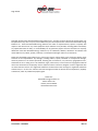
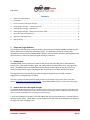
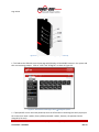
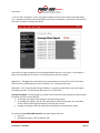
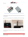
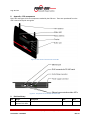
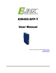
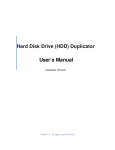
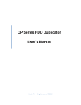
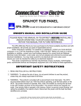
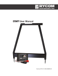
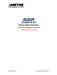
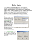
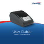
Page 1 of 13 AURORA® MICRO PHOTOVOLTAIC INVERTERS 13 May 2013 Application note: Improving CDD Wireless Signal Reception MICRO-0.25-I and MICRO-0.3-I READER NOTES: • This document is to be used in conjunction with the original installation manual or Quick Start guide for MICRO-0.25-I and MICRO-0.3-I. • All safety precautions in the full manual must be read, understood and followed. APPLICATION NOTE: Improving CDD Wireless Signal Reception Part Number: BCA.00041 REV AA Page 2 of 13 Copyright © 2013 Power-One Renewable Energy Solutions LLC. All rights reserved. No part of this document may be reproduced in any form or by any means without the prior written permission of Power-One Renewable Energy Solutions LLC. Power-One Renewable Energy Solutions LLC makes no representations, express or implied, with respect to this document or any of the equipment and/or software it may describe; including (without limitation) any implied warranties of utility, or merchantability for any particular purpose. All such warranties are expressly disclaimed. Power-One Renewable Energy Solutions LLC, its subsidiaries, affiliates, distributors and dealers shall not be liable for any indirect, special, incidental, or consequential damages under any circumstances. Power-One Renewable Energy Solutions LLC reserves the right to make changes to this document without notice and shall not be responsible for any damages, including indirect, special, incidental or consequential damages, caused by reliance on the content presented, including, but not limited to, any omissions, typographical errors, arithmetical errors or listing errors. All trademarks, logos, trade names, service marks and copyrighted materials used in this document are the property of their respective owners. Failure to designate a mark as registered does not mean that such mark is not a registered trademark. The Power-One name and logo are registered trademarks of Power-One, Inc. in the U.S.A. and other countries. All rights reserved. No licenses are conveyed herein, implicitly or otherwise, under any intellectual property rights. Power-One Renewable Energy Solutions LLC 3201 E. Harbour Dr. Phoenix, Arizona 85034 United States of America APPLICATION NOTE: Improving CDD Wireless Signal Reception Part Number: BCA.00041 REV AA Page 3 of 13 Contents 1 Scope and Target Audience ..................................................................................................................................3 2 Introduction ..........................................................................................................................................................3 3 How to check the radio signal strength ................................................................................................................3 4 Boosting signal strength – antenna orientation ...................................................................................................6 5 Boosting signal strength – CDD location ...............................................................................................................7 6 Boosting signal strength – CDD Antenna Extension Cable ....................................................................................8 7 Power-One Technical Support Line.....................................................................................................................12 8 Appendix – CDD components .............................................................................................................................13 9 Revision history ...................................................................................................................................................13 1 Scope and Target Audience 2 Introduction This document describes how to improve wireless communication between AURORA® MICRO inverters and the Power-One Concentrator Data Device (CDD). This application note is for installers and homeowners with Power-One AURORA MICRO Systems, who are familiar with basic CDD operations and who have a user’s manual or quick start guide nearby for reference. AURORA MICRO inverters report their status to the receiver unit (the CDD) over a radio frequency wireless link. If the signal strength is good, the process will be completed faster than if the signals are weak. The MICRO inverters and CDD automatically choose the best signal routing, but as with any wireless communication, signals may degrade due to obstacles or non-ideal antenna orientation. This application note discusses ways to check the signal strength seen by the CDD, and offers suggestions for strengthening it if needed. Note also any Frequently Asked Questions (FAQ) posted in the renewable energy section of the Power-One website (www.power-one.com/renewable-energy), in the AURORA MICRO section or on Resource Center pages. 3 How to check the radio signal strength The AURORA MICRO-CDD system must be installed, and the inverters acquired and recognized as described in the Instruction manual and Quick Start Guide, and set up for local monitoring as follows. (Note that local monitoring does not involve the AURORA Easy View program on the internet.) 1. Enter the IP address of the CDD in the URL address bar of an internet browser (e.g. Internet Explorer, Chrome, Firefox, Safari). The IP address can be viewed on the CDD screen by pressing the ESC button on the right side of the CDD (Figure 3-1). APPLICATION NOTE: Improving CDD Wireless Signal Reception Part Number: BCA.00041 REV AA Page 4 of 13 rd Figure 3-1 Right side of CDD unit showing ESC key, 3 from top 2. This leads to the CDD web server home page which displays all the MICRO inverters in the system and their current energy output. Click on "View” and “RF Signals" as shown in Figure 3-2. Figure 3-2 CDD webserver home page “View” “RF Signals” options 3. If prompted for a user name and password, enter the information in the dialog box which pops up on the screen (user name is admin, factory default password is admin; however, the password can be changed by the user). APPLICATION NOTE: Improving CDD Wireless Signal Reception Part Number: BCA.00041 REV AA Page 5 of 13 4. On the “View - RF Signals” screen, the signal strength from each inverter will be displayed (Figure 3-3). Although information will be displayed on the screen immediately, it takes about 15 minutes for the screen to acquire new data and refresh. Figure 3-3 Signal bar graph screen from View RF Signals page from the CDD web server There will be a signal strength bar for each AURORA MICRO inverter in the system. The example in Figure 3-3 shows data for 12 inverters. The following items will be of interest: msg column: The msg column shows how many data packets were received in the last 15 minutes. After 15 minutes of data collection, there should be a “15” showing on each row. rssi column: The “received signal strength indicator” is a measure of the power in the radio signals received by the CDD. The best system will have all “rssi” above 70%. Average Plant Signal: The percentage is a measure of the overall RF (radio frequency) communication link quality for each inverter-CDD link. • An average plant signal >70% indicates a well-performing system. • An average plant signal in the 40-70% range indicate a functioning system, but it may have slower refresh rates and possible delays in internal data transfer. • Average plant signals <40% are suboptimal, indicating poor communication quality To summarize; for reliable CDD operation, the signal requirements are • msg = 15 • average plant signal > 40%, preferably >70%. APPLICATION NOTE: Improving CDD Wireless Signal Reception Part Number: BCA.00041 REV AA Page 6 of 13 4 Boosting signal strength – antenna orientation If the signal strength is less than desired, the fastest and easiest item to check is the CDD radio antenna orientation (see Appendix, page 13 for the location of the radio antenna—the one on the right when facing the CDD screen). The radio antenna readily receives signals which come in from the side, but has a dead zone at its top and bottom (Figure 4-1). Because radio frequency signals bounce around, there will still be some reception of signals from the top of the antenna, but sideways orientation is better. A clear line of sight from antenna to the inverters is best. Nothing should be in contact with the part of the antenna above the base, as that other item will reduce the signal strength. Figure 4-1 CDD radio antenna (black, A) showing the best orientation for signal reception (green, B), and the worst (red, C) 1. If the radio antenna is pointed straight towards the AURORA MICROs (red X in Figure 4-2, below), turn it broadside (green √ mark in Figure 4-2). 2. After adjusting the antenna direction, wait 15 minutes for the CDD to receive a complete set of data and refresh its average plant signal strength screen. 3. Check the “msg” and “average plant signal” numbers on the “Microinverter RF signals” screen (Figure 3-3), looking for msg = 15 and for an improvement in the “average plant signal.” APPLICATION NOTE: Improving CDD Wireless Signal Reception Part Number: BCA.00041 REV AA Page 7 of 13 Figure 4-2 Correct orientation for CDD radio antenna, sideways to the AURORA MICRO inverters 5 Boosting signal strength – CDD location The best location for the CDD is as close as possible to the AURORA MICRO inverters, though of course, the location must be readily accessible to the user and reasonably close to the Wi-Fi router. Obstacles between the CDD and its AURORA MICRO inverters will degrade reception. Such obstacles are generally solid objects and include metal roof surfaces or other metal objects, metal-reinforced concrete and rebar, building frames, granite and other hard stone, bulletproof glass, some tinted class, some reflective surfaces, or even particle board. Table 5-1 shows typical signal degradation due to various objects and materials, compared to clear line-of-slight reception through open air, across a distance of an 100-yards (e.g. the length a football field). Table 5-1 Approximate RF signal attenuation expected through various materials Obstacle material Metal Metal-reinforced concrete Stone, particle board, pressed cardboard Wood, plain glass Signal degradation relative to an open field Up to 100% (complete blockage of signal) 10-90% (depending on the amount of metal) 10-40% 0-10% (little degradation of signals) If such items are in the way, or if the CDD is far from the inverters, try relocating the CDD, though it needs to remain close to an electrical outlet (for power), close enough to the Wi-Fi router to maintain the network connection, and where the connectors on the bottom of the unit remain accessible. Note that fog and rain can also affect signal transmission, but PV panels are not likely to be producing energy when it’s foggy or rainy! Dust storms are not likely to affect signal transmission, but may leave PV panels in need of cleaning. APPLICATION NOTE: Improving CDD Wireless Signal Reception Part Number: BCA.00041 REV AA Page 8 of 13 6 Boosting signal strength – CDD Antenna Extension Cable If a poor Average Plant Signal persists after all the recommendations in the Antenna Orientation and CDD location sections have been followed, then a Power-One “AURORA CDD ANTENNA EXTENSION CABLE” (Power-One Part Number ZLH.00563) may help boost the strength of the radio signals received by the CDD. The radio antenna is attached at the end of the extension cable, up to 45’ from the CDD. The CDD may then be placed in a convenient spot indoors, while the antenna itself is closer to the inverters, even outdoors, bypassing metal roofs, metal building structures, etc. The antenna extension cable is a coaxial cable approximately 45’ (15 meters) in length, has an outer diameter of 0.195” and coaxial terminals. It is rated for temperatures -40oF to 167oF (-40oC to 75oC). If the antenna is to be mounted indoors, special housing is not required, only a mounting bracket of plastic or other non-metallic material, as metal may interfere with antenna reception and transmission. If the radio antenna is to be mounted outdoors (for example, to bypass a metal roof), the external antenna may be set up using the following items supplied by Power-One: • CDD radio antenna (unscrew the radio antenna from the CDD) • CDD antenna extension cable (order from Power-One) The customer will need to supply the following items to create an external enclosure for the CDD Antenna: • Weatherproof, non-metallic junction box (sized to contain the antenna - e.g. BUD Industries PN-series, #1336) • Waterproof cable gland assembly (with seal and nut). ØA min-max = 3 – 7 mm / 0.118’’ – 0.275’’ See instructions below for attaching the antenna extension cable and creating the external enclosure. APPLICATION NOTE: Improving CDD Wireless Signal Reception Part Number: BCA.00041 REV AA Page 9 of 13 Instructions for attaching the antenna extension cable: 1. Unscrew the radio antenna from the top right side of the CDD. Wi-Fi antenna Radio antenna Figure 6-1 CDD Radio antenna (right) and WiFi antenna (left, not to be moved) If not using the external enclosure for outdoor mounting, skip step 2 and proceed to step 3. 2. If the antenna is to be mounted outside, thread the extension cable through the grommet and into the box. An example is shown in Figure 6-2, though note that the exact cable received from Power-One may vary in color and in other details. The box and grommets will be those supplied by the customer. Figure 6-2 Outdoor installation; mounting the radio antenna and water-tight grommet assembly in a plastic junction box APPLICATION NOTE: Improving CDD Wireless Signal Reception Part Number: BCA.00041 REV AA Page 10 of 13 3. Attach the antenna to the extension cable (Figure 6-3). Figure 6-3 45’ radio antenna extension cable attached to radio antenna If not using the external enclosure for outdoor mounting, skip step 4 and proceed to step 5. 4. Fit the antenna in the enclosure and tighten the cable glands. In the external enclosure, the base of the antenna should be visible above the grommet (Figure 6-4), leaving only the waterproof parts outside the box. Figure 6-4 Outdoor installation; base of radio antenna showing inside the weatherproof box A cable tie, mounted inside the enclosure, can be used to secure the antenna. An example of a completed outdoor antenna assembly is shown in Figure 6-5. APPLICATION NOTE: Improving CDD Wireless Signal Reception Part Number: BCA.00041 REV AA Page 11 of 13 cable tie Figure 6-5 Outdoor installation; example of CDD radio antenna mounted inside a plastic box with watertight seal 5. Mount the antenna or outdoor enclosure box where desired, with the antenna oriented sideways to the AURORA MICROs. 6. Screw the other end of the extension cable in to the AURORA CDD radio antenna connector (Figure 6-6). Figure 6-6 AURORA CDD with radio signal extension cable attached, top view (left) and bottom view closeup (right) 7. Check the Average Plant Signal again (Section 3, starting page 3), waiting 15 minutes for the screen to refresh (Figure 3-3). APPLICATION NOTE: Improving CDD Wireless Signal Reception Part Number: BCA.00041 REV AA Page 12 of 13 7 Power-One Technical Support Line If problems persist, call the Power-One customer support line at 1-877-261-1374 from Canada, the USA or Mexico. The Customer Information Center is open Monday - Friday (excluding major holidays), 6am 6pm, Mountain Standard Time; it does not switch to Daylight Savings Time in the summer. An answering service responds to calls outside normal business hours, taking call-back numbers and other contact information. Please have the following information available when calling: 1. Serial number(s) and other information on the label on the back side of the MICRO(s) 2. Serial number, MAC address and other information from the label on the back of the CDD 3. Name of the installer (if an installer put in the system) 4. Name of the site 5. Description of the problem--is it a one-time failure? Occurs daily and when? Is it a hard failure? 6. Conditions (weather, atmospheric, electrical) under which the problem occurs or occurred 7. List of things which have been tried to fix the problem, and what effect they had 8. Sections of the Installation and Operations or other manuals to which the caller has referred, and instructions which have already been completed. APPLICATION NOTE: Improving CDD Wireless Signal Reception Part Number: BCA.00041 REV AA Page 13 of 13 8 Appendix – CDD components Figure 8-1 and Figure 8-2 show components needed by the CDD user. These are reproduced from the user’s manual and quick start guide. Figure 8-1 User items on the front side of the CDD Figure 8-2 Components on the bottom side of the CDD 9 Rev AA Revision history Origin Power-One Italy & Phoenix Tech Docs Description Initial release Date 13 May 2013 ECO C28927 APPLICATION NOTE: Improving CDD Wireless Signal Reception Part Number: BCA.00041 REV AA