1
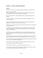
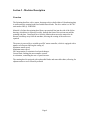
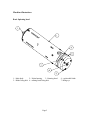
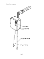
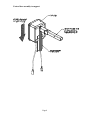
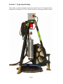
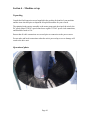
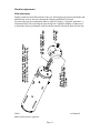
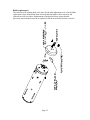
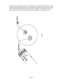
Spinning Head User Manual
Electric
1130 Blue Mound Road West, Ste 400. Haslet, TX 76052
Ph 817.439.1108 Fax 817.439.0633
www.machine-technologies.com
Rev3 – 10/11/07
Dear Customer,
Before starting this machine please complete the following;
Machine Date of purchase…………………………………..
Machine serial number………………………………………
Please read the following information contained within this manual and fully familiarize
yourself with the equipment.
Page 1
Contents
Page
Section 1 - General Safety information........................................................................... 3
Danger............................................................................................................................. 3
Section 2 - Machine Description ...................................................................................... 4
Function.......................................................................................................................... 4
Machine illustrations..................................................................................................... 5
Basic Spinning head ................................................................................................... 5
Exploded view of full machine .................................................................................. 6
Control box and mount.............................................................................................. 7
Control box assembly to support .............................................................................. 7
Control box assembly to support .............................................................................. 8
Section 3 –Typical positioning ......................................................................................... 8
Section 3 –Typical positioning ......................................................................................... 9
Section 4 – Machine set up ............................................................................................. 10
Unpacking..................................................................................................................... 10
Operational photo........................................................................................................ 10
Machine adjustments .................................................................................................. 11
Shim adjustment....................................................................................................... 11
Blade replacement .................................................................................................... 12
Section 5 – Machine operation / cleaning / maintenance............................................. 13
Notes for operation ...................................................................................................... 13
Notes for cleaning ........................................................................................................ 14
Notes for maintenance................................................................................................. 14
LIMITED WARRANTY POLICY .............................................................................. 17
Page 2
Section 1 - General Safety information
Danger
Follow these instructions very carefully, in order to avoid injury to yourself or others.
Electrically powered machine.
Always ensure that all power to the machine has been turned off and isolated before
ANY maintenance / repair work is carried out on the machine.
Ensure that all guards are correctly fitted before starting or attempting to operate the
machine.
Ensure that all fasteners are present and correctly fitted before attempting to start or
operate the machine.
Ensure that the rotating head on the end of the unit is correctly fastened, and free of
damage before attempting to start or operate the machine.
Ensure that the rotating head on the end of the unit rotates freely and true, if not then DO
NOT operate the unit
The spinning head produces high RPM on a heavy spinning plate with diffuser blades,
which can be dangerous. Care must be taken by authorized persons when using and
working with this machine.
DO NOT turn the unit on without it being correctly fastened to the tripod and winch
assembly, together with a hose attached to provide stability against the torque reaction
during start up.
DO NOT start the machine at any speed setting other than LOW, or the unit will “twist”
around causing damage to the unit, the mountings and possibly injury to the operator.
NEVER run material through the spinning head without the unit being within a collection
devise, or injury can result from flying material.
ALWAYS run the mortar pump at the lowest possible speed to do the job, to avoid
pressurization of the spinner and bearing damage.
ALWAYS grease the unit (see notes later in this document) prior to use.
Always perform a “clean up” between manholes. Ensure that ALL material is removed
from within the Nylon housing and around the drive shaft.
Page 3
Section 2 - Machine Description
Function
The Spinning head has a drive motor, that turns a drive shaft within a Nylon housing that
in turn rotates the rotating head fitted with diffuser blades. The drive motor is a 90V DC
unit rated at 1HP @ 2500 RPM.
Material is fed into the spinning head from a pressurized line into the side of the Nylon
housing, which then is redirected, axially, through the front of the unit out towards the
spinning end plate. Centrifugal force from the rotation then causes the material to be
thrown out and up away from the machine, allowing the coating of the surfaces to
repaired.
The motor is powered by a variable speed DC motor controller, which is equipped with a
number of trim pots allowing the setting of;
Maximum motor speed.
Minimum motor speed.
IR Compensation, to minimize load speed changes.
Current limit, limiting the max armature current.
Acceleration, controlling the rate of speed increase.
The rotating head is equipped with replaceable blades and removable shims, allowing for
adjustment due to wear caused by material
Page 4
Machine illustrations
Basic Spinning head
1 – Main body
2 – Nylon housing
3 – Rotating head
5 – Blade fixing bolt 6 – rotating head fixing bolt
Page 5
4 – replaceable blade
7- lifting eye
Exploded view of full machine
Page 6
Control box and mount
Page 7
Control box assembly to support
Page 8
Section 3 –Typical positioning
The machine is typically manually transported around the job site. The spinning head is
designed to be slung from a 115VAC winch unit, that is, itself supported from a tripod.
Page 9
Section 4 – Machine set up
Unpacking
Consult the final inspection record supplied in the packing for details of your machine
and the items checked prior to shipment. Keep this document for your records.
The spinning head requires assembly to the motor pump unit, the tripod, the winch, the
DC speed control. The DC speed control uses regular 115VAC power cord connections,
and should be fused at 15A.
Ensure that all cable connections are secured prior to connection to the power source.
Do not make and break connections when the unit is powered up as severe damage will
result to the drive unit
Operational photo
Page 10
Machine adjustments
Shim adjustment
During normal use the diffuser blades will wear, allowing the gap between the blades and
adjacent nose cone to increase reducing the slinging capabilities of the unit.
To reduce the gap, the rotating head must be removed, using a 3 leg puller with three ¼20 threaded legs, after removing the main fixing bolt. Adjust the number of shims used,
to obtain the correct performance with the chosen material. Retain all shims for later use.
If the wear is sufficiently high that there are no more shims to be removed, then the
blades will need to be replaced.
Page 11
Blade replacement
The removal of the rotating head is the same for the shim adjustment as it is for the blade
replacement. Once the head has been removed, then the blades can be removed, and
replaced in a full set of three. Replacement of the head will now require that the
previously removed shims need to be replaced to lift the new blades from the cone face
Page 12
Section 5 – Machine operation / cleaning / maintenance
Notes for operation
•
•
•
•
•
•
•
•
•
•
•
•
•
•
•
For starting the spinner, ensure that the speed control is at minimum.
Set up tripod over manhole. The legs lock into place when pulled out. Level the
tripod buy pulling the pins in the legs. The pins have a push pin in the head to
release them.
Install the winch in the slot on the underside of the tripod head. Install the keeper
pin through the holes that align with the winch. Install the safety pin into the
keeper pin. Winch should be level.
Attach the spinning head onto the safety hook on the winch.
With the spinner turned OFF, lower into the hole to the base. Raise by at least 6”
(or as required), and mark the cable at the drum. This marking is used to ensure
that the spinner NEVER touches the bottom of the hole during operation. Severe
damage can result if the touches the base during operation, such as bent shaft and
bearing damage.
Make sure control box is in off position before making connections. Connect cord
with cable connectors to control box and to spinning head. Connect 110VAC plug
to power source. Spinning head must be stabilized before turning on power, via
by hand or by attaching mortar hose. Spinning head will twist cable without
stability.
Do not touch the rotating head when testing or running unit.
Turn main power connection ON.
Move start switch to ON.
Adjust speed to desired speed (start at maximum, and adjust pump rate to suit).
Lower unit into manhole, so that material will not fly out.
Start the mortar pump unit at minimum speed to feed material to the spinning
head and start to lower into the hole.
Adjust material flow using pump speed until a smooth flow of material is flying
from the spinning head. (see photo of operation). DO NOT pump excessive
material into the spinner or pressurization will occur damaging the seals and
invalidating any and all warranties.
Continue lowering unit towards bottom of hole. Do not let unit touch bottom of
hole (look for the cable marker to appear on the drum). Raise unit back to top of
hole. Continue until walls are evenly coated. (approx 5 – 6 passes should provide
approx ½” coverage).
The mortar hose and power cable need to be attended to on the up and down
travel to keep them from twisting.
Page 13
Notes for cleaning
•
•
•
•
•
•
•
When a hole is complete, the spinning head must be cleaned. Remove from
winch, unscrew elbow on mortar inlet and flush with water using a high pressure
lance (DO NOT focus the jet towards the seal area). Completely wash out mortar
cavity and cup on bottom of unit.
When cleaning use a high pressure water jet into the mortar inlet in the Nylon
body.
The removal of ALL material from within the Nylon housing and from around the
drive shaft is critical, to prevent early failure of the front seal and then bearings.
It is recommended that between holes, that the bearing be greased with 1 slowly
applied pump of grease, without the removal of the grease vent port.
The unit is ready for the next hole.
To break down tripod pull down on the legs and they will fold inward.
Do not spray water on or in control box. Control box should be cleaned by being
wiped down with a damp rag or cloth.
Notes for maintenance
Grease to be used is No.730-2 Multipurpose grease, High temp, non-corrosive, extreme
pressure, anti-wear, water repellent, high resist to water, steam, acids and detergents.
White in color.
•
•
•
At the start of each job the unit should be greased, per the following instructions.
At the middle of the day the unit should again be greased, per the following
instructions.
At the end of the day the unit should be greased, per the following instructions.
Greasing the unit is a simple yet critical part of the use and maintenance of the spinning
head, as the grease physically keeps the material from entering into the bearing seal and
bearing cavity. Failure to perform this task correctly WILL result in bearing failure.
•
•
•
•
•
•
Clean both the grease nipple hole, the nipple and the grease vent hole.
Remove the grease vent set screw using a 3/16” hex key.
Assemble the grease gun to the nipple and pump grease until clean grease freely
flows in a constant stream from the vent hole, at the same time the rotating head
should be manually turned.
If the existing grease is not the same color as the grease being pumped in, then
this indicates that material is entering the bearing through the seal, and bearing
failure is imminent.
Replace the grease vent set screw, and lightly tighten down. Note do not over
tighten, or damage to the housing and or thread will occur.
Turn the rotating head manually and SLOWLY apply one to one and a half
additional pumps of grease, through the grease nipple, grease will be heard to pass
the front seal into the motor cavity.
Page 14
During each greasing operation, the free spinning of the rotating head should be checked,
feeling for signs of potential ingress of material into the bearing assembly, such as rough
rotation, the feeling of intermittent rotation, and or “grinding” in the bearings. If any of
these symptoms are felt then operation should stop and the unit returned for repair.
Page 15
•
In the event that the spinner bearings start to fail it is quite possible that the power
supply will become overloaded, and the re-settable fuse will trip. If this happens,
Turn off all power and disconnect form the supply, loosen the screws that keep
the lid closed, open the box, identify the fuse (see photo below) and press the top
until a click is heard and the fuse becomes reset.
Note. There are no user serviceable parts inside the control box.
Page 16
LIMITED WARRANTY POLICY
Machine Technologies warrants each of its new machines to be free of
defects in material and workmanship under normal use and services for a
period of one (1) year from the date of delivery.
The warranty is issued ONLY to the INITIAL USER. The warranty period
begins when the product is delivered to the initial user or when first put into
service, whichever occurs first. Said warranty is void if the machine is
subject to misuse, neglect, accident or abuse.
Machine Technologies’ obligation under this warranty is limited to
correcting without charge, at its warehouse, any parts or parts thereof which
shall be returned to its warehouse, transportation/shipping prepaid and upon
Machine Technologies’ examination proves to have been originally
defective. Correction of such defects by repair or replacement shall
constitute fulfillment of all obligations to the initial user. This warranty does
not include labor or transportation charges unless specifically identified and
authorized in writing by Machine Technologies. Nor does the warranty
apply to any unit upon which repairs or unauthorized alterations have been
made.
The warranty does not apply to normal maintenance service or to normal
replacement of certain machine parts which are subject to normal wear
(including but not limited to pins, bushings, rotors, stators, hoses, spray
caps, spray nozzles, mixing shafts, shaft couplings and connectors, dosing
shafts, pump shafts, filter elements and tires).
THIS IS A LIMITED WARRANTY AND IS IN LIEU OF ANY OTHER
WARRANTIES, EXPRESSED OR IMPLIED, INCLUDING ANY
WARRANTY OF MERCHANTABILITY OF FITNESS FOR A
PARTICULAR PURPOSE. In no event shall Machine Technologies be
made liable for incidental, general or consequential damage, loss or any
expense directly or indirectly related and resulting from use or lack of use
caused by delay in delivery, parts failure, or any other causes associated with
the product use. No person, firm or corporation is authorized to assume for
Machine Technologies any other liability in connection with the sale of
Machine Technologies products.
Page 17