1
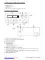
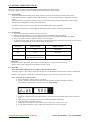
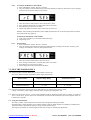
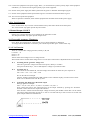
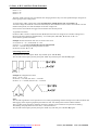
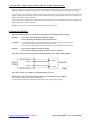
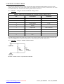
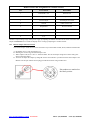
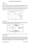
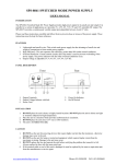
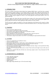
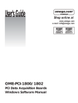
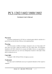
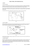
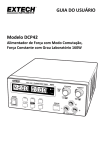
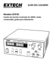
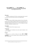
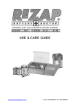
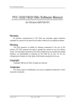
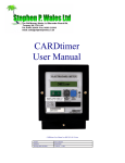
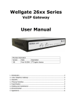
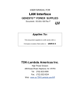
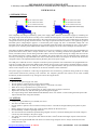
SSP-8160/SSP-8162/SSP-8320/SSP-8322
Laboratory Grade 160W/320W Constant Power Switched Mode Power Supply with USB Software Control
USER MANUAL
1. INTRODUCTION
This completely new design of laboratory grade power supply differs from the conventional supply by calculating the
changing voltage and current limits according to the available maximum power. This means that the maximum limits of
the voltage and current are changed according to the rated output power of the supply. The combinations of maximum
voltage and current are greatly increased and so is the range of operational limits as shown in the hyperbolic graph of
maximum power voltage-ampere opposite. A conventional power supply only has a set maximum voltage and a set
maximum current such that all the operating V & A must fall inside these limits. The benefits are clear, it saves money
and space as one constant-power SMPS (Switch Mode Power Supply) can do the work of multiple conventional units.
This family of efficient SMPS with a small form factor, auto cross-over between CV & CC, three user programmable VI
presets and remote control, offers a unique solution for a wide vary of loading conditions and applications. The dual
action (coarse/fine) rotary encoder tuning with MCU (Micro Control Unit) makes setting the voltage and current levels
fast, smooth and precise. Setting, changing, and checking the current limit level can be performed easily without the
necessity of shorting the output terminals. The remote control function allows the output to be turned on & off and the
voltage & current to be adjusted without touching the front panel of the power supply.
The USB port is added for access to computer controlled cyclical operations with a maximum of 20 programmable sets
of preset of voltage and current with different time duration and up to 999 cycles with the supplied software. The DC
ramp and waveform generator can either be panel set or by the supplied software with previews of the final waveform
shown on the computer. Note: user software can be written without the above limitations!
The power supply is suitable for a wide range of applications such as laboratory, production testing, field test of voltage
critical distant load and the powering of dc networks. The computer generated test routines can be used in R&D,
Production, Product Evaluation or QC testing and various other applications.
2. WARNING
•
•
•
•
•
•
•
Do not use the power supply near water.
Do not operate or touch the power supply with wet hands.
Do not open the casing of the power supply when it is connected to ac mains.
Refer all servicing to qualified service personnel only.
Before replacing the AC fuse located at the AC mains input socket, rectify the cause first.
Replace the AC fuse only with the same type and rating as the original.
The output voltage of the Model SSP8162 and SSP8322 can be over 60VDC. Avoid touching the metal parts of the
output terminals when using these models!
3. CAUTION
•
•
•
•
•
•
•
•
Always use a grounded three pin (earthed) AC source.
The unit is for indoor use only.
Do not operate or place this unit in a humid or dusty location. Avoid direct sunlight and keep away from any heat
source.
Before plugging in the AC mains plug, check the rating label at the back of the unit.
Do not block any ventilation openings of the unit.
This unit must be used within the specified rating. Regular excessive continuous loading above the rated voltage or
current may cause damage to the power supply.
The gauge size of the AC input power cable must be at least 0.75mm2 and the total length of power cable must not
exceed 3m.
Always use the supplied USB cable with ferrite core when using computer control. Always disconnect the USB
cable when not in use.
www.procontechnology.com.au for Manson
Phone: (03) 98306288
FAX: (03) 98306481
4. ENVIRONMENTAL OPERATING CONDITIONS
•
•
•
•
•
10-80% R.H.
Altitude up to 2000m
Installation category: CAT 2
Pollution degree: 2
Mains supply voltage fluctuation up to ±10% of the normal voltage
5. CONTROLS AND INDICATORS
Front
Rear
(1)
(2)
(3)
(4)
(5)
(6)
(7)
(8)
(9)
(10)
(11)
LED panel meter display with CC/CV/W Indictor
Remote Control Indicator (Remote Control or USB mode)
Output Voltage Control Knob
Output Current Control Knob
Power ON/OFF Switch
6 Keys illuminate Keypad:
- Preset Key 1, 2 & 3
- Menu Key (Shift Key)
- Lock/ Unlock Key (A/W meter Key)
- Output ON/OFF (∆V/∆t Key)
Output Safety Jacks (Rated for max. current output)
USB port
(For access to computer to run cyclical operations with programmable voltage, current, period time and cycle)
Remote Sensing Terminal
(Warning! Short-Circuiting the remote sensing terminals or connecting the sense terminals in reverse
polarity can damage the power supply)
Remote Control Socket
AC Inlet socket (with fuse holder)
www.procontechnology.com.au for Manson
Phone: (03) 98306288
FAX: (03) 98306481
6. CONTROL MODE SELECTION
There are 3 modes, Normal, Preset and Remote Control modes on the power supply.
The power supply is factory preset to Normal Mode with maximum current level CC.
6.1 Normal Mode
This is the default mode and the power supply outputs V and I are controlled by the dual action control
knobs. Push the knobs to toggle the coarse and fine tuning, notice the subtle changes in brightness of related
LED.
Adjust the knobs to your desired values by trying coarse and fine tuning. The maximum limits of the voltage
and current are changeable according to the rated power.
To check the preset current level, just turn the Current Knob lightly in any direction.
The display will resume its normal brightness after few seconds to double confirm your adjustment.
6.2 Preset Mode
a. There are 3 preset outputs (Preset 1/ Preset 2/ Preset 3)
b. Simply press the Preset key 1, 2 or 3 to enter the preset mode and the key will light up.
c. End user can adjust the preset output voltage and current by turning Voltage knob and Current knob.
d. The preset values are factory default as shown in following table.
e. To check the preset value, press the “Shift” Key and then the Preset Key which you want to check. The V and I
settings of corresponding P1, P2, P3 will be shown on the panel.
Preset No.
Output Voltage
Output Current
P1
5V
Maximum
P2
13.8V
Maximum
P3
SSP-8160/SSP-8320: 40V
SSP-8162/SSP-8322: 80V
Maximum
Remarks:
All the set values in the Presets will be kept even after the power supply has been turned off.
Always check output voltage of Presets before connect to Load
6.3 Menu Key
Press and hold the Menu key for 3 seconds to enter into the Set menu
The power supply is then ready to set the ∆V/∆t value or enter the Remote Control mode or Factory Reset Mode.
Remark: If no selection is made after 10 seconds, the power supply defaults to the previous setting.
6.3.1 To set the ∆V/∆t (dV/dt) value
a. Press and hold the “Menu” Key for 3 seconds
b. Turn the Voltage control knob until the panel meter displays wording ‘dudt SEt’ as below,
press Voltage control knob to confirm to enter the ∆V/∆t setting
c. Adjust the Voltage and Current control knobs to set the ∆V/∆t value. Details please refer to section 11
& 12
d. After setting, press Voltage control knob to confirm and return to Set menu
e. Press Menu key to leave the Set menu
f. To start the ∆V/∆t function, press “Shift” key and then press “∆V/∆t” key to run
g. To stop the∆V/∆t function, press “Shift” key and then press “∆V/∆t” key again.
www.procontechnology.com.au for Manson
Phone: (03) 98306288
FAX: (03) 98306481
6.3.2
To activate the Remote Control Mode
a. Press and hold the “Menu” Key for 3 seconds
b. Tune the Voltage control knob until the panel meter displays wording rC SEt as below, press Voltage
control knob to enter the remote control mode.
c.
d.
e.
f.
Turn the Current control knob to select remote ON or OFF
Press Voltage control knob to confirm and return to Set menu
Press Menu key to leave the Set menu
Please refer details of remote control connection to section 14
Remark: After activating the Remote Control Mode, all function keys on the front panel will be Locked
and Lock/Unlock key lights up.
To deactivate the Remote Control Mode
g. Press Lock/Unlock key to unlock all the function keys
h. Repeat step a to c
6.3.3
Factory Reset
a. Press and hold the “Menu” Key for 3 seconds
b. Turn the Voltage control knob until the panel meter displays wording “FACS SEt” as below, press
Voltage control knob to enter the Factory Reset mode.
c.
d.
e.
f.
Turn the Current control knob to select Yes or No
Press Voltage control knob to confirm and return to Set menu
Press Menu key to leave the Set menu
Power Supply will reboot with Factory Defaults
7. USING THE POWER SUPPLY
7.1 Each series has 2 models. Make sure you have used the correct one.
They have different output voltage and current ranges as following:
Model Number
Output Voltage Range
Total Rated Current
SSP-8160/SSP-8320
0 ~ 42V
0 ~ 10A/20A
SSP-8162/SSP-8322
0 ~ 84V
0 ~ 5A/10A
7.2 Check the rating label of the power supply and make sure it complies with your AC mains
voltage. Connect the power supply to the AC Mains using the provided power cord.
7.3 After turn ON the unit, the CV, V and A LED indicators light up displaying voltage and 0.0 current. To check the
set CC current level, just turn the current control knob one click in either direction. The current display returns to
0.0 after a few seconds.
7.4 Using the control knobs
The rotary encoder control knobs have fine and coarse tuning with clicking movement.
Push the knobs to toggle between coarse and fine tuning, notice the subtle changes in brightness of related LED.
Adjust the knobs to your desired values by trying coarse and fine tuning.
The display will resume its normal brightness after few seconds to confirm your adjustment.
www.procontechnology.com.au for Manson
Phone: (03) 98306288
FAX: (03) 98306481
7.5 Connect the equipment to the power supply. Red (+) is connected to the positive polarity input of the equipment
and Black (-) is connected to the negative polarity input of the equipment.
7.6 Switch on the power supply first and the panel meter & green CV Indicator should light up again.
7.7 Switch on the equipment and the panel meter & green CV Indicator should still remain in green.
7.8 You can now operate the equipment.
When an operation is finished, switch off the equipment first and then switch off the power supply.
8. Key Lock function
Press “Lock/Unlock” key to lock or unlock all function keys and control knobs on the front panel.
The “Lock/Unlock” key lights up when keys are locked.
9. Manual Output ON/OFF
Simply press “Output ON/OFF” key to manual set the output ON or OFF.
The “Output ON/OFF” key lights up when output is ON.
10. Changeable Ammeter /Wattmeter
Press “Shift” key and then press “Lock/Unlock” key to change Ammeter to Wattmeter.
To change back the Wattmeter to Ammeter, press “Shift” key and then press “Lock/Unlock” key
11. ∆V/∆t Function
There are 3 settable DC voltage generators, namely A, B, and
C. Preset 1 = A
Preset 2 = B
Preset 3 = C
∆V a-b means from voltage level A to voltage level B.
∆t a-b means time in seconds from voltage level A to level B, this transit time is adjustable from 0 to 20 seconds.
11.1.
Presetting the DC generator voltage level
There are 3 generator voltage levels that can be preset, namely A / B and C
First press the Preset key 1, 2 and 3 and adjust the voltage to your desired value.
11.2.
Presetting the ∆t
There are 6 sets of available ∆t , tune the Voltage control knob can show the cyclic sequence of
AB → BA → AC → CA → BC → CB
We use the AB as an example
Turn the Voltage control knob until “A-b” appears on the voltmeter display, turn the Current control
knob to set to desired transit time ∆t say 5sec.
11.3.
Generating The Ramp Up or Down DC output
Ramp up generator example:
Set A = 5V, B = 10V, ∆t a-b = 5s, FunA = 0s, FunB = 15s, runt = 1
Now connect the load to the output and turn on the output terminal by pressing the “OUTPUT
ON/OFF” button and note the output LED indicator.
Press “Preset 1” button and note the output voltage of 5V then push “SHIFT” button then “∆v/∆t” button.
The output voltage will ramp up from 5V to 10V in 5 seconds and stay at 10V level for 10 seconds. The
power output will then be switched off.
www.procontechnology.com.au for Manson
Phone: (03) 98306288
FAX: (03) 98306481
12. Func A/ B/ C and Wave Form Generator
Preset 1 = A
Preset 2 = B
Preset 3 = C
The Func A/B/C sets how long (0 to 600sec) the voltage generator stays on at the specified output voltage level
before going to other voltage level.
To set the Func A/B/C, please enter to ∆V/∆t setting first ( Details please refer to section 6.3.1)
Turn the Voltage control knob to select the Function you want and then turn the Current control knob to set the
duration time period (0 to 600 seconds)for the chosen voltage level.
Press Current control knob can toggle coarse and fine tune the time period.
To generate waveform,
the Func A/B/C is used in conjunction with ∆V/∆t (the time from one voltage level to another voltage level)
By using the above functions simultaneously, 3 reversible pairs (AB & BA, BC & CB, AC & CA)
can be used to generate waveform .
Example 1: Pulse waveform with 3sec at 10V and 1sec at 5V.
set A (Preset 1) = 5V , set B (Preset 2) = 10V
set Func. A = 1 seconds by turning the Current control knob
Func B = 3 seconds using the same procedure as above
Set ∆t a-b = 0 , Set ∆t b-a = 0
Generating Wave Form
To generate the waveform push “Shift” key and then press “∆V/∆t” Key
The waveform will repeat cyclically until push “Shift” key and then press “∆V/∆t” Key again .
Example 2: Triangular wave form
Set A = 5V, B = 10 V
Set ∆t a-b = 3 seconds, Set ∆t b-a = 3 seconds
Set Func. A = 3 seconds, Set Func. B = 3 seconds
Note:
The waveform generation can be operated via our remote programming software with preview of the waveform and
data logging of the output in graphical presentation as well. For details please see the software manual.
This is a rather tricky operation, check the Preset key carefully to see if both are lit up and one is flashing.
The flashing will jump from one to the other, A to B, then B to A.
The waveform will repeat cyclically until press “Shift” key and then press “∆V/∆t” Key again .
www.procontechnology.com.au for Manson
Phone: (03) 98306288
FAX: (03) 98306481
13. Set the UVL (Upper Voltage Limit) and UCL (Upper Current Limit)
When the voltage or current at the output terminal exceeds the set limiting values, the output will be cut off. These
additional protection features are necessary for a power supply with such a wide ranges of voltage and current.
To set the UVL, press “Shift” Key and then press Voltage control knob. The voltmeter will show the present limit
and the Ammeter will show SUuL, tune the Voltage control knob to your desired limit value. Press “Shift” key to
confirm and return to normal operation.
To set the UCL, press “Shift” Key and then press Current control knob. The Ammeter will show the present limit
and the Voltmeter will show SUCL, tune the Current control knob to your desired limit value. Press “Shift” key to
confirm and return to normal operation.
Remark: The UVL and UCL setting is defaulted as maximum output value.
14. REMOTE SENSING
Take note of all warnings as wrong disconnection sequence can damage the Power Supply
Warning:
Never short-circuit the Remote Sensing Terminals
Always disconnect the Remote Sensing Terminals first
Connection:
1. First complete the power connections between the power supply and the equipment.
2. Check, and make sure, the power connections are secure.
3. Then make connections between the Remote Sensing Terminals and the equipment.
Warning:
Never short the Remote Sensing Terminals.
Never connect the Remote Sensing Terminals in reverse polarity.
Fig.3 shows connections between Remote Sensing Terminals, Power output and Equipment.
The remote sensing wire should be AT LEAST 22AWG wire size.
Disconnection: The incorrect disconnection sequence can damage the power supply!
1. First disconnect the remote sensing connections.
2. Then disconnect the power connections between the power supply and equipment.
www.procontechnology.com.au for Manson
Phone: (03) 98306288
FAX: (03) 98306481
15. REMOTE CONTROL MODE
There are two methods for remote control of current and voltage adjustment. Both methods require the current
remote control to be set up in order for the remote control mode to be function correctly - otherwise the unit will be
in CC mode all the time. To activate this function, please refer to section 6.3.2
15.1
Method A - Using two external variable DC voltage sources
Remote Socket Pin Assignment for external variable voltage source
PIN
FUNCTIONS
REMARKS
1
Internal DC +5V
Less than 50mA
2
Voltage Adjust
0 - 5V
3
Current Adjust
0 - 5V
4
Ground
5
Output OFF
6
N.A.
7
N.A.
8
N.A.
Short to Ground
Check the output voltage range of the power supply by varying the external voltage source. Short circuit the main
output with 14AWG wire to check the display for CC setting varying the external voltage source.
15.2
Method B - Using 2 x 5K Ohm variable resistors
Remark: variable resistors or potentiometers 5Kohm.
www.procontechnology.com.au for Manson
Phone: (03) 98306288
FAX: (03) 98306481
Remote Socket Pin Assignment for variable resistor
PIN
FUNCTIONS
REMARKS
1
Internal DC +5V
Resistor end
2
Voltage Adjust
Variable part of resistor
3
Current Adjust
Variable part of resistor
4
Ground
5
Output OFF
6
N.A.
7
N.A.
8
N.A.
Other resistor end
Short to Ground
Check the output voltage range of the power supply by adjusting the 5Kohm variable resistor. Short circuit the main
output with 14AWG wire to check the display for CC setting by adjusting the variable resistor.
15.3
Remote Output ON/OFF Control
This remote output on/off control can be activated in any of the modes Normal, Preset, Remote and Set mode.
A. By default, Pin 5 is open and output is on.
B. Shorting Pin 5 to Pin 4 (ground) and output is off.
C. When output is off, the C.V. & C.C. LED will flash. The current output voltage and current setting will
show on the panel meter.
D. You also can adjust the output by voltage & current control knob to your desired value when output is off.
Remark: use the 8pin remote control plug provided and connect using 22AWG wire.
Pin numbers are marked on
the black portion.
www.procontechnology.com.au for Manson
Phone: (03) 98306288
FAX: (03) 98306481
16. FAULTS AND TROUBLE SHOOTING
16.1
OUP: Over Voltage Protection
All units have a built-in tracking Over Voltage Protection (OVP) feature. In the event of the output voltage
becoming significantly greater than the set value (due to a failure of the power supply’s regulation or due to an
externally applied voltage), the output will shut down and the following warning appears on the display.
To reset the power supply, switch off the unit and remove all loads. Switch the unit back on again and normal
operation should resume. If this problem persists, please contact your agent.
16.2
OTP: Over Temperature Protection
A sensor inside the power supply monitors the temperature and prevents the unit from becoming too hot. When
Over Temperature Protection triggers, the output power will shutdown and the following warning will appear on
the LED display. On receiving this warning, switch off the unit and remove all loads.
Allow the unit to cool down for 30 minutes. Check that the ambient temperature is within specifications. Check
if any of the vents are restricted or blocked. Also check that there is sufficient clearance around the power
supply. Listen carefully for the noise from the cooling fan when the unit is turned on. If the noise from the fan
does not occur during the power-up sequence, the fan is faulty, do not use the power supply and contact your
agent.
16.3
OCP: Over Current Protection
Normally the CC constant current mode controls the maximum current output of the power supply, should this fail
and the maximum current output of the unit be exceeded then the Over Current Protection is triggered. The OCP
minimizes the extent of damage to your load and to the power supply. Switch off the power supply as soon as the
following warning appears.
To reset the OCP warning, switch off the unit and remove the load. Switch the unit on again and cautiously
check that the power supply responds as normal. If this problem persists, contact your agent.
www.procontechnology.com.au for Manson
Phone: (03) 98306288
FAX: (03) 98306481