1
NPort W2150/2250 Plus Series
User’s Manual
www.moxa.com/product
Second Edition, June 2007
© 2008 Moxa Inc., all rights reserved.
Reproduction without permission is prohibited.
NPort W2150/2250 Plus Series User’s Manual
The software described in this manual is furnished under a license agreement and may be used only in
accordance with the terms of that agreement.
Copyright Notice
Copyright © 2008 Moxa Inc.
All rights reserved.
Reproduction without permission is prohibited.
Trademarks
MOXA is a registered trademark of Moxa Inc.
All other trademarks or registered marks in this manual belong to their respective manufacturers.
Disclaimer
Information in this document is subject to change without notice and does not represent a commitment on the
part of Moxa.
Moxa provides this document “as is,” without warranty of any kind, either expressed or implied, including, but
not limited to, its particular purpose. Moxa reserves the right to make improvements and/or changes to this
manual, or to the products and/or the programs described in this manual, at any time.
Information provided in this manual is intended to be accurate and reliable. However, Moxa assumes no
responsibility for its use, or for any infringements on the rights of third parties that may result from its use.
This product might include unintentional technical or typographical errors. Changes are periodically made to the
information herein to correct such errors, and these changes are incorporated into new editions of the publication.
Technical Support Contact Information
www.moxa.com/support
Moxa Americas:
Toll-free: 1-888-669-2872
Tel: +1-714-528-6777
Fax: +1-714-528-6778
Moxa China (Shanghai office):
Toll-free: 800-820-5036
Tel: +86-21-5258-9955
Fax: +86-10-6872-3958
Moxa Europe:
Tel: +49-89-3 70 03 99-0
Fax: +49-89-3 70 03 99-99
Moxa Asia-Pacific:
Tel: +886-2-8919-1230
Fax: +886-2-8919-1231
Table of Contents
Chapter 1
Introduction ...............................................................................................1-1
Overview .............................................................................................................................. 1-2
Package Checklist................................................................................................................. 1-2
Product Features ................................................................................................................... 1-3
Product Specifications .......................................................................................................... 1-3
WLAN .......................................................................................................................... 1-3
LAN.............................................................................................................................. 1-3
Serial............................................................................................................................. 1-4
Serial Communication Parameters................................................................................ 1-4
Software Features ......................................................................................................... 1-4
Power Requirements..................................................................................................... 1-4
Physical Properties ....................................................................................................... 1-4
Environmental Limits ................................................................................................... 1-4
Certifications ................................................................................................................ 1-4
Serial Port Pin Assignments ................................................................................................. 1-5
Chapter 2
Getting Started ..........................................................................................2-1
Overview .............................................................................................................................. 2-2
Panel Layout......................................................................................................................... 2-2
LED Indicators ..................................................................................................................... 2-3
Top Panel LED Indicators ............................................................................................ 2-3
End Panel LED Indicators ............................................................................................ 2-3
Pull High/Low Resistors for RS-422/485............................................................................. 2-3
Placement Options................................................................................................................ 2-5
Connecting the Hardware ..................................................................................................... 2-5
Connecting to the Network........................................................................................... 2-6
Connecting the Power................................................................................................... 2-6
Connecting to a Serial Device ...................................................................................... 2-6
Chapter 3
Initial IP Configuration ..............................................................................3-1
Overview .............................................................................................................................. 3-2
Factory Default IP Settings................................................................................................... 3-2
Using ARP to Assign IP Address ......................................................................................... 3-2
Using the Telnet Console to Assign IP Address................................................................... 3-3
Using the Serial Console to Assign IP Address.................................................................... 3-5
Chapter 4
Introduction to Operation Modes.............................................................4-1
Overview .............................................................................................................................. 4-2
Real COM Mode .................................................................................................................. 4-2
RFC2217 Mode .................................................................................................................... 4-3
TCP Server Mode ................................................................................................................. 4-3
TCP Client Mode.................................................................................................................. 4-4
UDP Mode............................................................................................................................ 4-4
Pair Connection Modes ........................................................................................................ 4-5
Ethernet Modem Mode......................................................................................................... 4-5
Terminal Applications .......................................................................................................... 4-6
Terminal ASCII Mode.................................................................................................. 4-6
Terminal Binary Mode ................................................................................................. 4-6
Reverse Terminal Mode ....................................................................................................... 4-7
Chapter 5
Web Console: Basic Settings...................................................................5-1
Overview .............................................................................................................................. 5-2
Web Browser Settings .................................................................................................. 5-2
Navigating the Web Console ........................................................................................ 5-3
Basic Settings ....................................................................................................................... 5-4
Server Name ................................................................................................................. 5-4
Server Location............................................................................................................. 5-4
Time Zone .................................................................................................................... 5-4
Local Time.................................................................................................................... 5-5
Time Server .................................................................................................................. 5-5
Chapter 6
Web Console: Network Settings ..............................................................6-1
Overview .............................................................................................................................. 6-2
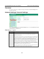
Network Settings> General Settings..................................................................................... 6-2
DNS Server 1 and 2 ...................................................................................................... 6-2
WINS Function............................................................................................................. 6-3
WINS Server................................................................................................................. 6-3
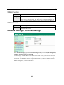
Network Settings> Ethernet Settings.................................................................................... 6-3
IP Configuration ........................................................................................................... 6-4
IP Address .................................................................................................................... 6-4
Netmask........................................................................................................................ 6-4
Gateway........................................................................................................................ 6-4
Speed ............................................................................................................................ 6-5
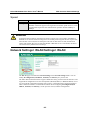
Network Settings> WLAN Settings> WLAN ...................................................................... 6-5
IP Configuration ........................................................................................................... 6-6
IP Address .................................................................................................................... 6-6
Netmask........................................................................................................................ 6-6
Gateway........................................................................................................................ 6-6
Network Settings> WLAN Settings> Profile ....................................................................... 6-7
Network Type ............................................................................................................... 6-8
Priority.......................................................................................................................... 6-9
Connect Rule ................................................................................................................ 6-9
Low Signal Strength Reconnect ................................................................................... 6-9
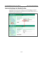
General Settings for WLAN Profile ................................................................................... 6-10
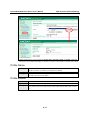
Profile Name............................................................................................................... 6-11
Profile Enable ............................................................................................................. 6-11
Operation Mode.......................................................................................................... 6-12
SSID ........................................................................................................................... 6-12
Channel....................................................................................................................... 6-12
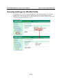
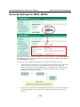
Security Settings for WLAN Profile................................................................................... 6-13
Authentication ............................................................................................................ 6-15
Encryption .................................................................................................................. 6-16
PSK Passphrase .......................................................................................................... 6-16
Security Settings for WEP Encryption ............................................................................... 6-17
WEP Key Length........................................................................................................ 6-17
WEP Key Index .......................................................................................................... 6-17
WEP Key Source ........................................................................................................ 6-18
WEP Passphrase ......................................................................................................... 6-18
WEP Key Format........................................................................................................ 6-18
WEP Key 1 Through 4 ............................................................................................... 6-18
Security Settings for WPA, WPA2..................................................................................... 6-19
EAP Method ............................................................................................................... 6-20
Tunneled Authentication ............................................................................................ 6-20
Username .................................................................................................................... 6-20
Password..................................................................................................................... 6-20
Anonymous Username................................................................................................ 6-21
Verify Server Certificate............................................................................................. 6-21
Trusted Server Certificate........................................................................................... 6-21
User Certificate........................................................................................................... 6-21
User Private Key......................................................................................................... 6-21
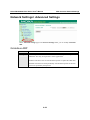
Network Settings> Advanced Settings ............................................................................... 6-22
Gratuitous ARP........................................................................................................... 6-22
Chapter 7
Web Console: Serial Port Settings ..........................................................7-1
Overview .............................................................................................................................. 7-3
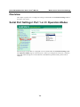
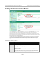
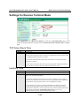
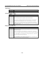
Serial Port Settings> Port 1 or 2> Operation Modes ............................................................ 7-3
Application ................................................................................................................... 7-4
Mode............................................................................................................................. 7-5
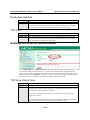
Settings for RealCOM Mode................................................................................................ 7-6
TCP Alive Check Time ................................................................................................ 7-6
Max Connection ........................................................................................................... 7-7
Ignore Jammed IP......................................................................................................... 7-7
Allow Driver Control.................................................................................................... 7-8
Connection Goes Down................................................................................................ 7-8
Packet Length ............................................................................................................... 7-8
Delimiter 1 and 2 .......................................................................................................... 7-9
Delimiter Process.......................................................................................................... 7-9
Force Transmit............................................................................................................ 7-10
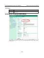
Settings for RFC2217 Mode............................................................................................... 7-10
TCP Alive Check Time .............................................................................................. 7-11
TCP Port ..................................................................................................................... 7-11
Packet Length ............................................................................................................. 7-11
Delimiter 1 and 2 ........................................................................................................ 7-11
Delimiter Process........................................................................................................ 7-12
Force Transmit............................................................................................................ 7-12
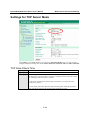
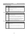
Settings for TCP Server Mode............................................................................................ 7-13
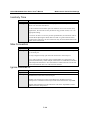
TCP Alive Check Time .............................................................................................. 7-13
Inactivity Time ........................................................................................................... 7-14
Max Connection ......................................................................................................... 7-14
Ignore Jammed IP....................................................................................................... 7-14
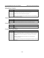
Allow Driver Control.................................................................................................. 7-15
TCP Port ..................................................................................................................... 7-15
Cmd Port..................................................................................................................... 7-15
Connection Goes Down.............................................................................................. 7-15
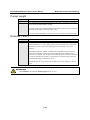
Packet Length ............................................................................................................. 7-16
Delimiter 1 and 2 ........................................................................................................ 7-16
Delimiter Process........................................................................................................ 7-17
Force Transmit............................................................................................................ 7-17
Settings for TCP Client Mode ............................................................................................ 7-18
TCP Alive Check Time .............................................................................................. 7-18
Inactivity Time ........................................................................................................... 7-19
Ignore Jammed IP....................................................................................................... 7-19
Destination Address 1 to 4.......................................................................................... 7-19
Designated Local Port 1 to 4 ...................................................................................... 7-20
Connection Control..................................................................................................... 7-20
Packet Length ............................................................................................................. 7-20
Delimiter 1 and 2 ........................................................................................................ 7-21
Delimiter Process........................................................................................................ 7-21
Force Transmit............................................................................................................ 7-22
Settings for UDP Mode ...................................................................................................... 7-22
Destination Address 1 to 4.......................................................................................... 7-23
Local Listen Port ........................................................................................................ 7-23
Packet Length ............................................................................................................. 7-23
Delimiter 1 and 2 ........................................................................................................ 7-23
Delimiter Process........................................................................................................ 7-24
Force Transmit............................................................................................................ 7-24
Settings for Pair Connection Modes ................................................................................... 7-25
TCP Alive Check Time .............................................................................................. 7-25
Destination Address.................................................................................................... 7-26
TCP Port ..................................................................................................................... 7-26
Settings for Ethernet Modem Mode ................................................................................... 7-26
TCP Alive Check Time .............................................................................................. 7-26
TCP Port ..................................................................................................................... 7-27
Settings for Terminal ASCII Mode .................................................................................... 7-27
TCP Alive Check Time .............................................................................................. 7-28
Inactivity Time ........................................................................................................... 7-28
Auto-Link Protocol..................................................................................................... 7-28
Primary and Secondary Host Address ........................................................................ 7-29
Telnet TCP Port .......................................................................................................... 7-29
Terminal Type ............................................................................................................ 7-29
Max. Sessions ............................................................................................................. 7-29
Change Session........................................................................................................... 7-29
Quit............................................................................................................................. 7-29
Break........................................................................................................................... 7-29
Interrupt ...................................................................................................................... 7-30
Authentication Type ................................................................................................... 7-30
Auto-login Prompt...................................................................................................... 7-30
Password Prompt ........................................................................................................ 7-30
Login User Name........................................................................................................ 7-30
Login Password .......................................................................................................... 7-31
Settings for Terminal Binary Mode.................................................................................... 7-31
TCP Alive Check Time .............................................................................................. 7-32
Inactivity Time ........................................................................................................... 7-32
Auto-Link Protocol..................................................................................................... 7-32
Primary and Secondary Host Address ........................................................................ 7-33
Telnet TCP Port .......................................................................................................... 7-33
Terminal Type ............................................................................................................ 7-33
Quit............................................................................................................................. 7-33
Authentication Type ................................................................................................... 7-33
Auto-login Prompt...................................................................................................... 7-34
Password Prompt ........................................................................................................ 7-34
Login User Name........................................................................................................ 7-34
Login Password .......................................................................................................... 7-34
Settings for Reverse Terminal Mode.................................................................................. 7-35
TCP Alive Check Time .............................................................................................. 7-35
Inactivity Time ........................................................................................................... 7-35
TCP Port ..................................................................................................................... 7-36
Authentication Type ................................................................................................... 7-36
Map Keys <CR-LF>................................................................................................... 7-36
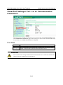
Serial Port Settings> Port 1 or 2> Communication Parameters.......................................... 7-37
Port Alias .................................................................................................................... 7-37
Baud Rate ................................................................................................................... 7-38
Data Bits ..................................................................................................................... 7-38
Stop Bits ..................................................................................................................... 7-38
Parity........................................................................................................................... 7-38
Flow Control............................................................................................................... 7-38
FIFO ........................................................................................................................... 7-38
Interface...................................................................................................................... 7-38
Serial Port Settings> Port 1 or 2> Data Buffering/Log....................................................... 7-39
Port Buffering ............................................................................................................. 7-39
Serial Data Logging.................................................................................................... 7-39
Serial Port Settings> Welcome Message............................................................................ 7-40
Chapter 8
Web Console: System Management........................................................8-1
Overview .............................................................................................................................. 8-3
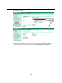
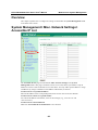
System Management> Misc. Network Settings> Accessible IP List.................................... 8-3
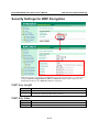
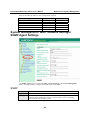
System Management> Misc. Network Settings> SNMP Agent Settings ............................. 8-4
SNMP ........................................................................................................................... 8-4
Read Community String ............................................................................................... 8-5
Write Community String .............................................................................................. 8-5
Contact Name ............................................................................................................... 8-5
Location........................................................................................................................ 8-5
SNMP Agent Version ................................................................................................... 8-5
Read Only User Name .................................................................................................. 8-5
Read Only Authentication Mode .................................................................................. 8-5
Read Only Password..................................................................................................... 8-6
Read Only Privacy mode .............................................................................................. 8-6
Read Only Privacy........................................................................................................ 8-6
Read/Write User Name................................................................................................. 8-6
Read/Write Authentication Mode................................................................................. 8-6
Read/Write Password ................................................................................................... 8-6
Read/Write Privacy mode............................................................................................. 8-6
Read/Write Privacy....................................................................................................... 8-6
System Management> Misc. Network Settings> Host Table............................................... 8-7
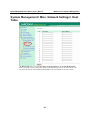
System Management> Misc. Network Settings> User Table............................................... 8-8
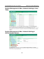
System Management> Misc. Network Settings> Authentication Server ............................. 8-8
RADIUS Server IP ....................................................................................................... 8-9
RADIUS Key................................................................................................................ 8-9
UDP Port....................................................................................................................... 8-9
RADIUS Accounting.................................................................................................... 8-9
System Management> Misc. Network Settings> System Log Settings................................ 8-9
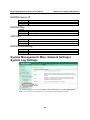
System Management> Auto Warning Settings> Event Settings ........................................ 8-10
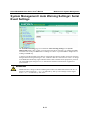
System Management> Auto Warning Settings> Serial Event Settings .............................. 8-11
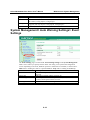
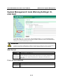
System Management> Auto Warning Settings> E-mail Alert ........................................... 8-12
Mail Server ................................................................................................................. 8-12
From E-mail Address.................................................................................................. 8-12
To E-mail Address 1 to 4 ............................................................................................ 8-13
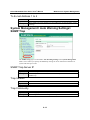
System Management> Auto Warning Settings> SNMP Trap ............................................ 8-13
SNMP Trap Server IP................................................................................................. 8-13
Trap Version ............................................................................................................... 8-13
Trap Community......................................................................................................... 8-13
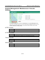
System Management> Maintenance> Console Settings..................................................... 8-14
HTTP Console ............................................................................................................ 8-14
HTTPS Console.......................................................................................................... 8-14
Telnet Console............................................................................................................ 8-14
SSH Console............................................................................................................... 8-14
Reset Button ............................................................................................................... 8-15
System Management> Maintenance> Ping ........................................................................ 8-15
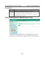
System Management> Maintenance> Firmware Upgrade ................................................. 8-16
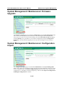
System Management> Maintenance> Configuration Import ............................................. 8-16
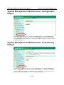
System Management> Maintenance> Configuration Export ............................................. 8-17
System Management> Maintenance> Load Factory Default ............................................. 8-17
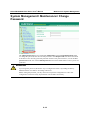
System Management> Maintenance> Change Password ................................................... 8-18
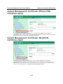
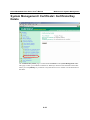
System Management> Certificate> Ethernet SSL Certificate Import ................................ 8-19
System Management> Certificate> WLAN SSL Certificate Import .................................. 8-19
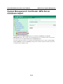
System Management> Certificate> WPA Server Certificate Import.................................. 8-20
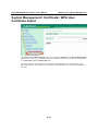
System Management> Certificate> WPA User Certificate Import .................................... 8-21
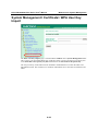
System Management> Certificate> WPA User Key Import............................................... 8-22
System Management> Certificate> Certificate/Key Delete ............................................... 8-23
Chapter 9
Web Console: System Monitoring ...........................................................9-1
Overview .............................................................................................................................. 9-2
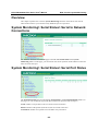
System Monitoring> Serial Status> Serial to Network Connections.................................... 9-2
System Monitoring> Serial Status> Serial Port Status ......................................................... 9-2
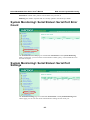
System Monitoring> Serial Status> Serial Port Error Count................................................ 9-3
System Monitoring> Serial Status> Serial Port Settings ...................................................... 9-3
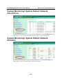
System Monitoring> System Status> Network Connections................................................ 9-4
System Monitoring> System Status> Network Statistics ..................................................... 9-4
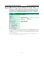
System Monitoring> System Status> Serial Data Log ......................................................... 9-5
System Monitoring> System Status> System Log ............................................................... 9-6
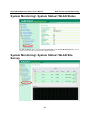
System Monitoring> System Status> WLAN Status............................................................ 9-7
System Monitoring> System Status> WLAN Site Survey ................................................... 9-7
Chapter 10
Web Console: Save and Restart ............................................................10-1
Overview ............................................................................................................................ 10-2
Save Configuration............................................................................................................. 10-2
Restart> Restart System ..................................................................................................... 10-2
Restart> Restart Ports ......................................................................................................... 10-3
Chapter 11
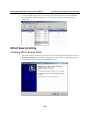
Installing and Configuring the Software ...............................................11-1
Overview ............................................................................................................................ 11-2
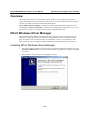
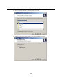
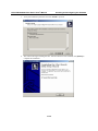
NPort Windows Driver Manager........................................................................................ 11-2
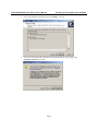
Installing NPort Windows Driver Manager................................................................ 11-2
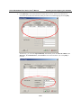
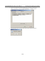
Adding Mapped Serial Ports....................................................................................... 11-5
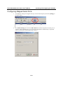
Configuring Mapped Serial Ports ............................................................................... 11-8
NPort Search Utility ......................................................................................................... 11-11
Installing NPort Search Utility ................................................................................. 11-11
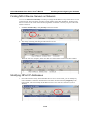
Finding NPort Device Servers on Network .............................................................. 11-14
Modifying NPort IP Addresses................................................................................. 11-14
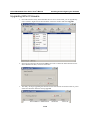
Upgrading NPort Firmware ...................................................................................... 11-16
Linux Real TTY Drivers................................................................................................... 11-17
Basic Steps................................................................................................................ 11-17
Installing Linux Real TTY Driver Files ................................................................... 11-17
Mapping TTY Ports.................................................................................................. 11-18
Removing Mapped TTY Ports.................................................................................. 11-19
Removing Linux Driver Files................................................................................... 11-19
UNIX Fixed TTY Drivers ................................................................................................ 11-19
Installing the UNIX Driver....................................................................................... 11-19
Configuring the UNIX Driver .................................................................................. 11-20
Appendix A
SNMP Agents with MIB II & RS-232-Like Groups .................................. A-1
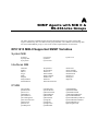
RFC1213 MIB-II Supported SNMP Variables.................................................................... A-1
System MIB................................................................................................................. A-1
Interfaces MIB............................................................................................................. A-1
IP MIB ......................................................................................................................... A-1
ICMP MIB................................................................................................................... A-2
UDP MIB..................................................................................................................... A-2
Address Translation..................................................................................................... A-2
TCP MIB ..................................................................................................................... A-2
SNMP MIB.................................................................................................................. A-2
RFC1317: RS-232 MIB Objects.......................................................................................... A-1
Generic RS-232-like Group......................................................................................... A-1
RS-232-like General Port Table .................................................................................. A-1
RS-232-like Asynchronous Port Group....................................................................... A-1
The Input Signal Table ................................................................................................ A-1
The Output Signal Table.............................................................................................. A-1
Appendix B
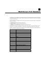
Well Known Port Numbers ...................................................................... B-1
Appendix C
Ethernet Modem Commands................................................................... C-1
Dial-in Operation..................................................................................................................C-1
Dial-out.................................................................................................................................C-1
Disconnection Request from Local Site ...............................................................................C-1
Disconnection Request from Remote Site ............................................................................C-2
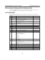
AT Commands......................................................................................................................C-2
S Registers............................................................................................................................C-3
Appendix D
Federal Communication Commission Interference Statement ............ D-1
Appendix E
FCC Warning Statement .......................................................................... E-1
1
Introduction
Chapter 1
The following topics are covered in this chapter:
Overview
Package Checklist
Product Features
Product Specifications
¾ WLAN
¾ LAN
¾ Serial
¾ Serial Communication Parameters
¾ Software Features
¾ Power Requirements
¾ Error! Reference source not found.
¾ Environment
¾ Certifications
Serial Port Pin Assignments
NPort W2150/2250 Plus Series User’s Manual
Introduction
Overview
In this chapter we introduce the basic features and specifications of the NPort W2150/2250 Plus
and NPort W2150/2250 Plus-T, referred to collectively as the NPort W2150/2250 Plus Series.
The NPort W2150/2250 Plus Series of wireless device servers are used to connect RS232/422/485 serial devices such as PLCs, meters, and sensors, to a wired Ethernet LAN or
wireless LAN. Your communications software will be able to access the serial devices from
anywhere over a local LAN, WLAN, or the Internet. Moreover, the WLAN environment offers an
excellent solution for applications in which the serial devices are moved frequently from place to
place.
The NPort W2150/2250 Plus supports both automatic IP configuration protocols (DHCP, BOOTP)
and manual configuration using a standard web browser. Both IP configuration methods ensure
quick and effective installation. In addition, a utility called “NPort Windows Driver Manager”
makes port mapping easy.
The external antenna can be adjusted for maximum signal strength. You can also choose to use
your own antenna for additional flexibility and scalability. A signal strength indicator on the front
panel makes it easier for you to troubleshoot any connection problems.
The NPort W2150/2250 Plus Series offers different operation modes to ensure compatibility with
standard network APIs, including TCP Server Mode, TCP Client Mode, and UDP Mode. Real
COM/TTY drivers are provided to allow legacy serial-based software to communicate over an IP
network instantly. This preserves your software investment while providing all the advantages of
networking your serial devices.
For easier management, the NPort W2150/2250 Plus include features such as password
authentication, IP filtering, 64-bit and 128-bit WEP encryption, and SNMP support.
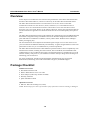
Package Checklist
Standard Accessories
y Document & Software CD
y RJ45 to RJ45 Ethernet cross-over cable
y Power adaptor (wide temp. models excluded)
y Warranty statement
y Quick Installation Guide
Optional Accessories
y DK-35A: DIN-rail mounting kit (35 mm)
NOTE: Please notify your sales representative if any of the above items are missing or damaged
1-2
NPort W2150/2250 Plus Series User’s Manual
Introduction
Product Features
y
y
y
y
y
y
y
y
y
Instant connection of any serial device to IEEE 802.11a/b/g network
RS-232/422/485 ports supporting baudrates up to 921.6 Kbps
Web-based configuration over Ethernet or WLAN
Enhanced remote configuration with HTTPS, SSH
Secure data access with WEP, WPA, WPA2
Built-in WLAN site survey Tool
User-defined behavior for wireless roaming with signal strength thresholds
Off-line port buffering and serial data log for each serial port
Dual power inputs (1 power jack, 1 terminal block)
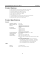
Product Specifications
WLAN
Standard Compliance
Radio Frequency Type
Tx Power
Rx Sensitivity
Transmission Rate
Transmission Distance
Antenna Connector
Network Mode
Wireless Security
802.11a/b/g
DSSS/OFDM
17 dBm (typical) for Tx Power 11b
15 dBm (typical) for Tx Power 11g
14 dBm (typical) for Tx Power 11a
-80 dBm
54 Mbps for 802.11a
11 Mbps for 802.11b
54 Mbps for 802.11g
54 Mbps (max.) with auto fallback
(54, 48, 36, 24, 18, 12, 11, 9, 6, 5.5, 2, 1 Mbps)
Up to 100 meters (in open areas)
Reverse SMA
Infrastructure mode, Ad-Hoc mode
WEP: 64-bit/128-bit data encryption
WPA, WPA2, 802.11i: Enterprise mode and Pre-Share Key (PSK)
mode
Encryption: 128-bit TKIP/CCMP
802.11i WAP authentication: PEAP, EAP-TLS, EAP-TTLS,
PEAP/MSCHAPv2, PEAP/TLS, PEAP/GTC, ,PEAP/MD5,
AP-TTLS/EAP-MD5, EAP-TTLS/EAP-GTC, EAP-TTLS,
EAP-TTLS/EAP-MSCHAPv2, EAP-TTLS/EAP-TLS,
EAP-TTLS/MSCHAPv2, EAP-TTLS/MSCHAP
LAN
Ethernet
Protection
10/100 Mbps (RJ45)
Built-in 1.5 KV magnetic isolation
1-3
NPort W2150/2250 Plus Series User’s Manual
Introduction
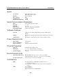
Serial
No. of Ports
Interface
Port Connector
Serial Data Log
Off-Line Port Buffering
NPort W2150 Plus: 1 port
NPort W2250 Plus: 2 ports
RS-232/422/485
DB9
64 KB
64 KB
Serial Communication Parameters
Parity
Data Bits
Stop Bits
Flow Control
Transmission Speed
None, Even, Odd, Space, Mark
5, 6, 7, 8
1, 1.5, 2
RTS/CTS, XON/XOFF, DTR/DSR
50 bps to 921.6 Kbps
Software Features
Protocols
Utilities
Configuration
ICMP, IP, TCP, UDP, DHCP, BOOTP, Telnet, SNMP, HTTP,
SMTP
Windows 98, ME, 2000, XP, 2003, XP x64, 2003 x64, Vista, Vista
x64
Web browser, serial console, Telnet console, Windows utility
Power Requirements
Power Input
Power Consumption
Power Connector
12 to 48 VDC
560 mA
Power jack and terminal block
Physical Properties
Material
Dimensions
Antenna Length
Aluminum sheet metal (1 mm)
77 × 111 × 26 mm (no ears, no antenna)
100 × 111 × 26 mm (with ears, no antenna)
109 mm
Environmental Limits
Operating Temperature
Storage Temperature
Standard Mode: 0 to 55°C (32 to 131°F), 5 to 95%RH
Wide Temp. Mode: -40 to 75°C (-40 to 167°F), 5 to 95%RH
-20 to 85°C (-4 to 185°F), 5 to 95%RH
Certifications
EMC
Safety
CE: EN55022 Class A/EN55024, ETSI EN 301 489-17,
ETSI EN 301 489-1
FCC: FCC Part 17 Subpart B, Class A, FCC Part 15 Subpart B,
Class A
UL: UL60950-1
TÜV: EN60950-1
DSPR: ARIB-STD 33, ARIB-STD 66
1-4
NPort W2150/2250 Plus Series User’s Manual
Introduction
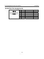
Serial Port Pin Assignments
1 2 3 4 5
6 7 8 9
Pin
1
2
3
4
5
6
7
8
9
RS-232
DCD
RXD
TXD
DTR
GND
DSR
RTS
CTS
---
1-5
RS-422/ RS-485 (4W)
TxD-(A)
TxD+(B)
RxD+(B)
RxD-(A)
GND
---------
RS-485 (2W)
----Data+(B)
Data-(A)
GND
---------
2
Getting Started
Chapter 2
The following topics are covered in this chapter:
Overview
Panel Layout
LED Indicators
¾ Top Panel LED Indicators
¾ End Panel LED Indicators
Pull High/Low Resistors for RS-422/485
Placement Options
Connecting the Hardware
¾ Connecting to the Network
¾ Connecting the Power
¾ Connecting to a Serial Device
NPort W2150/2250 Plus Series User’s Manual
Getting Started
Overview
This chapter presents the hardware features of the NPort W2150/W2250 Plus Series and explains
how to connect the hardware.
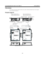
Panel Layout
NPort W2150 Plus/
NPort W2150 Plus-T
NPort W2250 Plus/
NPort W2250 Plus-T
100M LED (green)
10M LED (orange)
Reset
button
Power jack
power input
RJ45 10/100 Mbps
Ethernet port
Antenna
Terminal Block
power input
DIN-Rail
screw hole
Signal Strength LEDs
Wallmount screw hole
Male DB9 connector
2-2
NPort W2150/2250 Plus Series User’s Manual
Getting Started
LED Indicators
Top Panel LED Indicators
Name
Color
Function
Steady on:
Blinking:
Power is on and NPort is booting up.
IP conflict or DHCP/ BOOTP server did not
respond properly.
Steady on: NPort is functioning normally.
Blinking: Unit is responding to Locate function.
Power is off or a power error condition exists.
Wireless enabled.
Wireless not enabled.
Serial port is receiving data.
Serial port is transmitting data.
No data is flowing to or from the serial port.
More LEDs indicates better signal; 5 LEDs indicates maximum
signal strength.
Red
Ready
Green
WLAN
Serial 1
Serial 2
Signal Strength
(5 LEDS)
Off
Green
Off
Orange
Green
Off
Green
End Panel LED Indicators
Name
Ethernet
Color
Orange
Green
Off
Function
10 Mbps Ethernet connection
100 Mbps Ethernet connection
Ethernet cable is disconnected or has a short
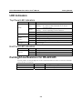
Pull High/Low Resistors for RS-422/485
You may need to set the pull high/low resistors when termination resistors are used for certain RS422 or RS-485 environments.
Serial Port
Port 1
Port 2
Jumpers
JP5 and JP6
JP7 and JP8
2-3
Pull High/Low Setting
150 KΩ=both open, 1 KΩ=both shorted
150 KΩ=both open, 1 KΩ=both shorted
NPort W2150/2250 Plus Series User’s Manual
Getting Started
NPort W2150 Plus, NPort W2150 Plus-T
NPort W2250 Plus, NPort W2250 Plus-T
ATTENTION
Do not use the 1 KΩ setting while in RS-232 mode. Doing so will degrade the RS-232 signals
and reduce the effective communication distance.
2-4
NPort W2150/2250 Plus Series User’s Manual
Getting Started
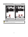
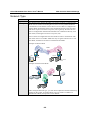
Placement Options
The NPort can be placed on a desktop or other horizontal surface. You can also install the NPort
on a DIN-rail or on the wall.
DIN-Rail Mounting
Wall Mounting
Connecting the Hardware
ATTENTION
Before connecting the hardware, follow these important wiring safety precautions:
Disconnect power source
Do not install or wire this unit or any attached devices with the power connected. Disconnect the
power before installation by removing the power cord before installing and/or wiring your unit.
Follow maximum current ratings
Calculate the maximum possible current in each power wire and common wire. Observe all
electrical codes dictating the maximum current allowable for each wire size.
If the current goes above the maximum ratings, the wiring could overheat, causing serious
damage to your equipment.
Use caution - unit may get hot
The unit will generate heat during operation, and the casing may feel hot to the touch. Take care
when handling unit. Be sure to leave adequate space for ventilation.
2-5
NPort W2150/2250 Plus Series User’s Manual
Getting Started
The following guidelines will help ensure trouble-free signal communication with the NPort.
y Use separate paths to route wiring for power and devices to avoid interference. Do not run
signal or communication wiring and power wiring in the same wire conduit. The rule of thumb
is that wiring that shares similar electrical characteristics can be bundled together.
y If power wiring and device wiring paths must cross, make sure the wires are perpendicular at
the intersection point.
y Keep input wiring and output wiring separate.
y Label all wiring to each device in the system for easier testing and troubleshooting
Connecting to the Network
Use the supplied Ethernet cable to connect the NPort to your Ethernet network. If the cable is
properly connected, the NPort will indicate a valid connection to the Ethernet as follows:
y A green Ethernet LED indicates a valid connection to a 100 Mbps Ethernet network.
y An orange Ethernet LED indicates a valid connection to a 10 Mbps Ethernet network.
y A flashing Ethernet LED indicates that Ethernet packets are being transmitted or received.
Connecting the Power
Connect the VDC power line (12 to 48 V) to the NPort’s power jack or terminal block. If power is
properly connected, the “Ready” LED will initially glow red. When the system is ready, the
“Ready” LED will turn green.
Connecting to a Serial Device
Use a serial cable to connect your serial device to a serial port on the NPort.
2-6
3
Initial IP Configuration
Chapter 3
The following topics are covered in this chapter:
Overview
Factory Default IP
Using ARP to Assign IP Address
Using the Telnet Console to Assign IP Address
Using the Serial Console to Assign IP Address
NPort W2150/2250 Plus Series User’s Manual
Initial IP Configuration
Overview
This chapter presents several ways to assign the NPort’s IP address for the first time. Please refer
to Chapter 2 for instructions on connecting to the network.
The web console is the recommended method for configuring the NPort. Please refer to Chapter 5
and 6 for details on using the web console for configuration.
ATTENTION
The LAN and WLAN interfaces cannot be used at the same time. If the Ethernet link is active,
then WLAN connections will be disabled. If the WLAN connection is active, then the Ethernet
link will be disabled.
ATTENTION
Make sure that the Ethernet cable is connected before powering up the NPort.
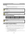
Factory Default IP Settings
Network Interface
LAN
WLAN
IP Configuration
Static
Static
IP Address
192.168.126.254
192.168.127.254
Netmask
255.255.255.0
255.255.255.0
If your NPort is configured to obtain its IP settings from a DHCP or BOOTP server but is unable
to get a response, it will use the factory default IP address and netmask.
ATTENTION
If you forget the IP address of your NPort, you can look it up using the NPort Search Utility. After
NPort Search Utility has found all NPorts on the network, each unit will be listed with its IP
address. Please refer to Chapter 11 for additional information on using NPort Search Utility.
Using ARP to Assign IP Address
The ARP (Address Resolution Protocol) command can be used to assign an IP address to the NPort.
The ARP command tells your computer to associate the NPort’s MAC address with the specified
IP address. You must then use Telnet to access the NPort, at which point the device server’s IP
address will be reconfigured. This method only works when the NPort is configured with default
IP settings.
1.
2.
3.
Select a valid IP address for your NPort. Consult with your network administrator if necessary.
Obtain the NPort’s MAC address from the label on its bottom panel.
From the DOS prompt, execute the arp -s command with the desired IP address and the
NPort’s MAC address, as in the following example:
arp -s 192.168.200.100 00-90-E8-xx-xx-xx
In this example 192.168.200.100 is the new IP address that will be assigned to the NPort, and
00-90-E8-xx-xx-xx is the NPort’s MAC address.
3-2
NPort W2150/2250 Plus Series User’s Manual
4.
5.
Initial IP Configuration
From the DOS prompt, execute a special Telnet command using port 6000, as in the
following example:
telnet 192.168.200.100 6000
In this example, 192.168.200.100 is the new IP address that will be assigned to the NPort.
You should see a message indicating that the connection failed.
The NPort will automatically reboot with the new IP address. You can verify that the
configuration was successful by connecting to the new IP address with Telnet, ping, the web
console, or NPort Search Utility.
Using the Telnet Console to Assign IP Address
1.
2.
Select Run… from the Windows Start menu.
Enter telnet 192.168.126.254 (the NPort’s default IP address) and click [OK].
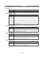
3.
Select the terminal type and press ENTER.
4.
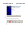
Press N or use the cursor keys to select Network and press ENTER.
5.
Press E or use the cursor keys to select Ethernet and press ENTER.
3-3
NPort W2150/2250 Plus Series User’s Manual
Initial IP Configuration
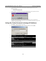
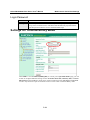
6.
Use the cursor keys to navigate between the different fields. For IP address, Netmask, and
Gateway, enter the desired values directly. For IP configuration and LAN speed, press
ENTER to open a submenu and select between the available options.
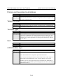
7.
Press ESC to return to the menu. Press ESC again to return to the main menu. When
prompted, press Y to save the configuration changes.
8.
Press R or use the cursor keys to select Restart and press ENTER. Press ENTER again to
select System.
When prompted, press ENTER to proceed. The NPort will reboot with the new IP settings.
3-4
NPort W2150/2250 Plus Series User’s Manual
Initial IP Configuration
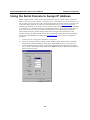
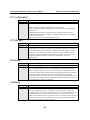
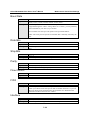
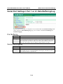
Using the Serial Console to Assign IP Address
Before using the NPort’s serial console, turn off the power and use a serial cable to connect the
NPort console port to your computer’s serial port. Port 1 on the NPort serves as the console port. is
Port 1Connect to the console port with a serial-based terminal or terminal emulator program, such
as Windows HyperTerminal. You may also download PComm Lite at www.moxa.com. The
terminal type should be set as ANSI or VT100, and the serial communication parameters should be
set as 19200, 8, N, 1 (19200 for baud rate, 8 for data bits, None for parity, and 1 for stop bits). As
soon as the connection is open, you will be presented with a text menu displaying the NPort
W2150/2250 Plus Series general settings. Please refer to Chapter 4 for a description of the
available settings. The following instructions We recommend using PComm Terminal Emulator,
which can be downloaded free of charge from www.moxa.com, to carry out the configuration
procedure.
1.
2.
3.
Connect your PC’s serial port to the NPort’s console port.
Open your terminal emulator program, such as Windows HyperTerminal. We recommend
using PComm Terminal Emulator, which can be downloaded for free at www.moxa.com.
In your terminal emulator program, configure the communication parameters for the serial
port on the PC. The parameters should be set to 19200 for baud rate, 8 for data bits, None for
parity, and 1 for stop bits.
3-5
NPort W2150/2250 Plus Series User’s Manual
Initial IP Configuration
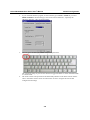
4.
In your terminal emulator program, set the terminal type to ANSI or VT100. If you select
Dumb Terminal as the terminal type, some of the console functions—especially the
“Monitor” function—may not work properly.
5.
Hold the grave accent key (`) down and power up the NPort.
6.
The continuous string of grave accent characters triggers the NPort to switch from data mode
to console mode.
The serial console will open and will be functionally identical to the Telnet console. Please
refer to the Telnet console section for instructions on how to navigate the console and
configure the IP settings.
3-6
4
Introduction to Operation Modes
Chapter 4
The following topics are covered in this chapter:
Overview
Real COM Mode
RFC2217 Mode
TCP Server Mode
TCP Client Mode
UDP Mode
Pair Connection Modes
Ethernet Modem Mode
Terminal Applications
¾ Terminal ASCII Mode
¾ Terminal Binary Mode
Reverse Terminal Mode
NPort W2150/2250 Plus Series User’s Manual
Introduction to Operation Modes
Overview
This chapter introduces the different serial port operation modes that are available on the NPort
W2150/2250 Plus Series. Each serial port on the NPort is configured independently of the other
ports, with its own serial communication parameters and operation mode. The serial port’s
operation mode determines how it interacts with the network, and different modes are available to
encompass a wide variety of applications and devices.
Real COM and RFC2217 modes allow serial-based software to access the NPort serial port as if it
were a local serial port on a PC. These modes are appropriate when your application relies on
Windows or Linux software that was originally designed for locally attached COM or TTY
devices. With these modes, you can access your devices from the network using your existing
COM/TTY-based software, without investing in additional software.
Three different socket modes are available for user-developed socket programs: TCP Server,
TCP Client, and UDP Server/Client. For TCP applications, the appropriate mode depends on
whether the connection will be hosted or initiated from the NPort serial port or from the network.
The main difference between the TCP and UDP protocols is that TCP guarantees delivery of data
by requiring the recipient to send an acknowledgement to the sender. UDP does not require this
type of verification, making it possible to offer speedier delivery. UDP also allows multicasting of
data to groups of IP addresses and would be suitable for streaming media or non-critical
messaging applications such as LED message boards.
Pair Connection Slave and Master modes are designed for serial-to-serial communication over
Ethernet, in order to overcome traditional limitations with serial transmission distance.
In Ethernet Modem mode, the NPort acts as an Ethernet modem, providing a network connection
to a host through the serial port.
Terminal ASCII and Binary modes are designed to connect serial-based terminals to a server on
the network.
Reverse Telnet mode is designed for connections to servers that will host terminal sessions
through the NPort serial port. This mode is typically used for console management applications,
but can also be used to upgrade legacy servers to network operation.
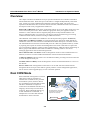
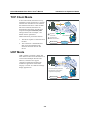
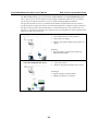
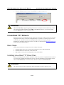
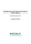
Real COM Mode
Real COM mode is designed to work with
NPort drivers that are installed on a
network host. COM drivers are provided
for Windows systems, and TTY drivers
are provided for Linux and UNIX systems.
The driver establishes a transparent
connection to the attached serial device by
mapping a local serial port to the NPort
serial port. Real COM mode supports up
to four simultaneous connections, so
multiple hosts can collect data from the
attached device at the same time.
Real COM Mode
TCP/IP
WLAN
Proceed directly with data
transmission (connection
request not required)
NPort W2250
Ethernet
Antenna
Ready
WLAN
Serial 1
Serial 2
W2250
Wireless Serial Device Server
Port 1
RS-232/422/485
Serial Device
4-2
Reset
12-48 VDC
Serial Signal
Port 2
RS-232/422-485
NPort W2150/2250 Plus Series User’s Manual
Introduction to Operation Modes
ATTENTION
Real COM drivers are installed and configured through NPort Windows Driver Manager.
Real COM mode allows you to continue using your serial communications software to access
devices that are now attached to your NPort device server. On the host, the NPort Real COM
driver automatically intercepts data sent to the COM port, packs it into a TCP/IP packet, and
redirects it to the network. At the other end of the connection, the NPort device server accepts the
Ethernet frame, unpacks the TCP/IP packet, and sends the serial data to the appropriate device.
ATTENTION
In Real COM mode, several hosts can have simultaneous access control over the NPort serial
port. If necessary, you can limit access by using the NPort’s Accessible IP settings. Please refer to
Chapter 8 for additional information on Accessible IP settings.
RFC2217 Mode
RFC-2217 mode is similar to Real COM mode, since it relies on a driver to transparently map a
virtual COM port on a host computer to a serial port on the NPort. The RFC2217 standard defines
general COM port control options based on the Telnet protocol and supports one connection at a
time. Third party drivers supporting RFC-2217 are widely available on the Internet and can be
used to implement virtual COM mapping.
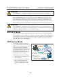
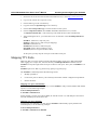
TCP Server Mode
In TCP Server mode, the NPort serial
port is assigned an IP:port address that is
unique on your TCP/IP network. It waits
for the host computer to establish a
connection to the attached serial device.
This operation mode also supports up to
four simultaneous connections, so
multiple hosts can collect data from the
attached device at the same time.
Data transmission proceeds as follows:
TCP Server Mode
1
1 Request a
connection
TCP/IP
WLAN
2
NPort W2250
Ethernet
Reset
Antenna
12-48 VDC
Ready
WLAN
Serial 1
Serial 2
2 Proceed with
data transmission
1. A host requests a connection to the
NPort serial port.
W2250
Wireless Serial Device Server
Port 1
RS-232/422/485
Serial Device
2. Once the connection is established,
data can be transmitted in both
directions—from the host to the
device, and from the device to the
host.
4-3
Serial Signal
Port 2
RS-232/422-485
NPort W2150/2250 Plus Series User’s Manual
Introduction to Operation Modes
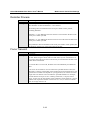
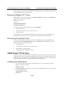
TCP Client Mode
In TCP Client mode, the NPort actively
establishes a TCP connection to a specific
network host when data is received from
the attached serial device. After the data
has been transferred, the NPort can
automatically disconnect from the host
computer through the Inactivity time
settings. Please refer to Chapter 7 for
details on these parameters.
Data transmission proceeds as follows:
TCP Client Mode
TCP/IP
WLAN
1
1 Request a
connection
2
NPort W2250
Ethernet
Reset
Antenna
12-48 VDC
Ready
WLAN
Serial 1
Serial 2
1. The NPort requests a connection from
the host.
2. The connection is established and
data can be transmitted in both
directions between the host and
device.
2 Proceed with
data transmission
W2250
Wireless Serial Device Server
Port 1
RS-232/422/485
Serial Device
Port 2
RS-232/422-485
Serial Signal
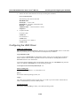
UDP Mode
UDP is similar to TCP but is faster and
more efficient. Data can be broadcast to or
received from multiple network hosts.
However, UDP does not support
verification of data and would not be
suitable for applications where data
integrity is critical. It is ideal for message
display applications.
UDP Mode
TCP/IP
WLAN
Proceed directly with data
transmission (connection
request not required)
NPort W2250
Ethernet
Reset
Antenna
12-48 VDC
Ready
WLAN
Serial 1
Serial 2
W2250
Wireless Serial Device Server
Port 1
RS-232/422/485
Serial Device
4-4
Serial Signal
Port 2
RS-232/422-485
NPort W2150/2250 Plus Series User’s Manual
Introduction to Operation Modes
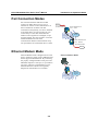
Pair Connection Modes
Pair Connection Mode
Device
Port 2
RS-232/422-485
RS-232/422/485
Port 1
RS-232/422/485
Wireless Serial Device Server
NPort W2250/2150
Plus Slave
W2250
Serial 2
Serial 1
WLAN
Ready
12-48 VDC
Reset
Ethernet
Antenna
Pair Connection Master and Slave modes
connect two NPort device servers over a
network for serial-to-serial communication. A
device attached to one NPort can then
communicate transparently to a device attached
to the other NPort, as if the two devices were
connected by a serial cable. Both data and
modem control signals are exchanged, except
for DCD signals. This can be used to overcome
traditional limitations with serial
communication distance and introduces many
new possibilities for serial-based device control.
TCP/IP
WLAN
Ethernet
Reset
Antenna
12-48 VDC
Ready
WLAN
Serial 1
Serial 2
W2250
Wireless Serial Device Server
Port 1
RS-232/422/485
NPort W2250/2150
Plus Master
Port 2
RS-232/422-485
RS-232/422/485
Device
Ethernet Modem Mode
Ethernet Modem Mode
RS-232
Port 1
RS-232/422/485
Port 2
RS-232/422-485
Wireless Serial Device Server
W2250
Ethernet Modem mode is designed for use with
legacy operating systems, such as MS-DOS, that
do not support TCP/IP Ethernet. By connecting
the properly configured NPort serial port to the
MS-DOS computer’s serial port, it is possible to
use legacy software to transmit data over the
Ethernet when the software was originally
designed to transmit data over a modem.
Serial 2
Serial 1
WLAN
Ready
12-48 VDC
Ethernet
Reset
Antenna
TCP/IP
WLAN
4-5
NPort W2150/2250 Plus Series User’s Manual
Introduction to Operation Modes
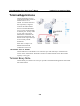
Terminal Applications
Terminal applications involve
connecting terminals to UNIX or
Windows servers over a
network. A terminal connects to
the appropriately configured
serial port the NPort, and the
NPort transmits information to
and from a UNIX or Windows
server over the network through
its Ethernet port. You may need
to check with your network
administrator to determine the
appropriate terminal mode. All
terminal modes support fast keys
as used in many terminal
applications.
Please refer to Chapter 7 for
detailed information and
configuration instructions.
Terminal ASCII Mode
Terminal ASCII mode can handle up to 8 sessions per port with the ability to switch between
sessions on the same terminal. This mode is used for text-based terminals with no file transfer
capability or encryption.
Terminal Binary Mode
Terminal binary mode allows one session per port and is used for terminal applications that include
file transfer features.
4-6
NPort W2150/2250 Plus Series User’s Manual
Introduction to Operation Modes
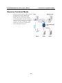
Reverse Terminal Mode
In Reverse Telnet mode, the NPort serial port
is connected to a server and waits for a
terminal session to from a host on the
network. This is an appropriate mode for
console management, with NPort serial ports
connected to the console/AUX or COM ports
of routers, switches, or UPS units. Unlike
TCP Server mode, Reverse Telnet mode
assists with CR/LF conversion.
4-7
5
Web Console: Basic Settings
Chapter 5
The following topics are covered in this chapter:
Overview
¾ Web Browser Settings
¾ Navigating the Web Console
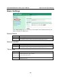
Basic Settings
¾ Server Name
¾ Server Location
¾ Time Zone
¾ Local Time
¾ Time Server
NPort W2150/2250 Plus Series User’s Manual
Web Console: Basic Settings
Overview
This chapter introduces the NPort web console and explains how to configure the basic settings.
The NPort can be configured from anywhere on the network through its web console. Simply point
the browser to the device server’s IP address to open the web console. Network settings, operation
mode, and other items can all be configured through the browser.
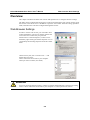
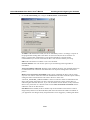
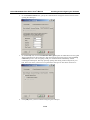
Web Browser Settings
In order to use the web console, you will need to have
cookies enabled for your browser. Please note that the
web console uses cookies only for password
transmission. For Internet Explorer, cookies can be
enabled by right-clicking the Internet Explorer icon on
your desktop and selecting Properties from the context
menu.
On the Security tab, click “Custom Level…” and
enable these two items:
Allow cookies that are stored on your computer.
Allow per-session cookies (not stored).
ATTENTION
If you are not using Internet Explorer, cookies are usually enabled through a web browser setting
such as “allow cookies that are stored on your computer” or “allow per-session cookies.”
5-2
NPort W2150/2250 Plus Series User’s Manual
Web Console: Basic Settings
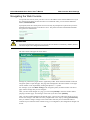
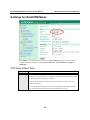
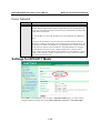
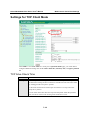
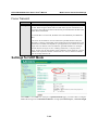
Navigating the Web Console
To open the web console, enter your device server’s IP address in the website address line. If you
are configuring the NPort for the first time over an Ethernet cable, you will use the default IP
address, 192.168.126.254.
If prompted, enter the console password. You will only be prompted for a password if you have
enabled password protection on the device server. The password will be transmitted with MD5
encryption over the Ethernet.
ATTENTION
If you have forgotten the password, you can use the reset button to load factory defaults, but this
will erase all previous configuration information.
The web console will appear as shown below.
Settings are presented on pages that are organized by folder. Select the desired folder in the left
navigation panel to open that page. The page will be displayed in the main window on the right.
Certain folders can be expanded by clicking the adjacent “+” symbol.
For example, if you click Basic Settings in the navigation panel, the main window will show a
page of basic settings that you can configure.
After you have made changes on a page, you must click [Submit] in the main window before
jumping to another page. Your changes will be lost if you do not click [Submit].
After you have finished modifying the desired pages, you must save and restart the device server
for the new settings to take effect. You may complete this in one step by clicking [Save/Restart]
after you submit a change. Changes will not take effect until they are saved and the NPort is
restarted. If you restart the NPort without saving your configuration, all configuration changes will
be lost.
5-3
NPort W2150/2250 Plus Series User’s Manual
Web Console: Basic Settings
Basic Settings
On the Basic Settings page, you can configure Server name, Server location, Time zone (24hour), Local time, and Time server.
Server Name
Default
Options
Description
NPW2150P_<serial no.> or NPW2250P_<serial no.>
free text (e.g., “Server 1”)
This is an optional free text field to help you differentiate one device server
from another. It does not affect operation of the NPort device server.
Server Location
Default
Options
Description
free text (e.g., “Bldg 1, 2nd Floor”)
This is an optional free text field to help you differentiate one device server
from another. It does not affect operation of the NPort device server.
Time Zone
Default
Options
Description
(GMT)Greenwich Mean Time
(GMT)Greenwich Mean Time
(GMT-01:00)Azores, Cape Verde Is.
(GMT-02:00)Mid-Atlantic
etc.
This field shows the currently selected time zone and allows you to select a
different time zone.
5-4
NPort W2150/2250 Plus Series User’s Manual
Web Console: Basic Settings
Local Time
Default
Options
Description
Date (yy:mm:dd), Time (hh:mm:ss)
The NPort has a built-in real-time clock that allows you to add time information
to functions such as the automatic warning e-mail or SNMP trap. This field
shows the current time according to the NPort’s built-in real-time clock. This is
not a live field, so you will need to refresh the browser to get an updated
reading.
Click [Modify] to adjust the real-time clock. Make sure that you first select the
correct time zone. The real-time clock will be updated immediately, with no
need to restart the NPort.
ATTENTION
There is a risk of explosion if the real-time clock battery is replaced incorrectly!
The real time clock is powered by a lithium battery. We strongly recommend that you obtain
assistance from a Moxa support engineer before replacing the battery. Please contact the Moxa
RMA service team if you need to change the battery.
Time Server
Default
Options
Description
IP address or domain name (e.g., “192.168.1.1” or “time.nist.gov”)
This optional field specifies your time server’s IP address or domain name, if a
time server is used in your network. The NPort supports SNTP (RFC-1769) for
automatic time calibration. The device server will request time information
from the specified time server every 10 minutes.
5-5
6
Web Console: Network Settings
Chapter 6
The following topics are covered in this chapter:
Overview
Network Settings> General Settings
¾ DNS Server 1 and 2
¾ WINS Function
¾ WINS Server
Network Settings> Ethernet Settings
¾ IP Configuration
¾ IP Address
¾ Netmask
¾ Gateway
¾ Speed
Network Settings> WLAN Settings>
WLAN
¾ IP Configuration
¾ IP Address
¾ Netmask
¾ Gateway
Network Settings> WLAN Settings>
Profile
¾ Network Type
¾ Priority
¾ Connect Rule
¾ Low Signal Strength Reconnect
General Settings for WLAN Profile
¾ Profile Name
¾ Profile Enable
¾ Operation Mode
¾ SSID
¾ Channel
Security Settings for WLAN Profile
¾ Authentication
¾ Encryption
¾ PSK Passphrase
Security Settings for WEP Encryption
¾ WEP Key Length
¾ WEP Key Index
¾ WEP Key Source
¾ WEP Passphrase
¾ WEP Key Format
¾ WEP Key 1 Through 4
Security Settings for WPA, WPA2
¾ EAP Method
¾ Tunneled Authentication
¾ Username
¾ Password
¾ Anonymous Username
¾ Verify Server Certificate
¾ Trusted Server Certificate
¾ User Certificate
¾ User Private Key
Network Settings> Advanced Settings
¾ Gratuitous ARP
NPort W2150/2250 Plus Series User’s Manual
Web Console: Network Settings
Overview
This chapter explains how to configure all settings located under the Network Settings folder in
the NPort web console.
Network Settings> General Settings
On the General Settings page in the Network Settings folder, you can modify DNS server 1 and
2, WINS function, and WINS server.
DNS Server 1 and 2
Default
Options
Description
IP address (e.g., “192.168.1.1”)
This field is for the DNS server’s IP address, if applicable. With the DNS server
configured, the NPort device server can use domain names instead of IP
addresses to access hosts.
Domain Name System (DNS) is how Internet domain names are identified and
translated into IP addresses. A domain name is an alphanumeric name, such as
www.moxa.com, that it is usually easier to remember than the numeric IP
address. A DNS server is a host that translates a text-based domain name into an
IP address in order to establish a TCP/IP connection. When the user wants to
visit a particular website, the user’s computer sends the domain name (e.g.,
www.moxa.com) to a DNS server to request that website’s numeric IP address.
When the IP address is received from the DNS server, the user’s computer uses
that information to connect to the website’s web server.
The NPort will play the role of a DNS client, actively querying the DNS server
for the IP address associated with a particular domain name.
6-2
NPort W2150/2250 Plus Series User’s Manual
Web Console: Network Settings
WINS Function
Default
Options
Description
Enable
Enable, Disable
This field enables or disables the WINS (Windows Internet Naming Service)
server. TCP/IP uses IP addresses to identify hosts, but users often use symbolic
names, such as computer names. The WINS server, which uses NetBIOS over
TCP/IP, contains a dynamic database to map computer names to IP addresses.
WINS Server
Default
Options
Description
IP address (e.g., “192.168.0.201”)
This field specifies the WINS server’s IP address, if a WINS Server is
connected to the network.
Network Settings> Ethernet Settings
On the Ethernet Settings page in the Network Settings folder, you can modify IP configuration,
IP address, Netmask, Gateway, and Speed.
You must assign a valid IP address to the NPort before it will work in your network environment.
Your network system administrator should provide you with an IP address and related settings for
your network. The IP address must be unique within the network; otherwise the NPort will not
have a valid connection to the network. First-time users should refer to Chapter 3, “Initial IP
Address Configuration,” for more information.
6-3
NPort W2150/2250 Plus Series User’s Manual
Web Console: Network Settings
IP Configuration
Default
Options
Description
Static
Static, DHCP, DHCP/BOOTP, BOOTP
This field determines how the NPort’s IP address will be assigned.
Static: IP address, netmask, and gateway are user-defined.
DHCP: IP address, netmask, gateway, DNS, and time server are assigned by
DHCP server.
DHCP/BOOTP: IP address, netmask, gateway, DNS, and time server are
assigned by DHCP server. IP address is assigned by BOOTP server if DHCP
server does not respond.
BOOTP: IP address is assigned by BOOTP server.
IP Address
Default
Options
Description
192.168.126.254
IP address (e.g., “192.168.1.1”)
This field is for the IP address that will be assigned to your NPort device server.
An IP address is a number assigned to a network device (such as a computer) as
a permanent address on the network. Computers use the IP address to identify
and talk to each other over the network. Choose a proper IP address that is
unique and valid in your network environment. If your device server will be
assigned a dynamic IP address, set the “IP configuration” parameter
appropriately.
Netmask
Default
Options
Description
255.255.255.0
Netmask setting (e.g., “255.255.0.0”)
This field is for the subnet mask. A subnet mask represents all of the network
hosts at one geographic location, in one building, or on the same local area
network. When a packet is sent out over the network, the NPort device server
will use the subnet mask to check whether the desired TCP/IP host specified in
the packet is on the local network segment. If the address is on the same
network segment as the device server, a connection is established directly from
the device server. Otherwise, the connection is established through the gateway
as specified in the “Gateway” parameter.
Gateway
Default
Options
Description
IP address (e.g., “192.168.1.1”)
This field is for the IP address of the gateway, if applicable. A gateway is a
network computer that acts as an entrance to another network. Usually, the
computers that control traffic within the network or at the local Internet service
provider are gateway nodes. The NPort device server needs to know the IP
address of the default gateway computer in order to communicate with the hosts
outside the local network environment. Consult your network administrator if
you do not know how to set this parameter.
6-4
NPort W2150/2250 Plus Series User’s Manual
Web Console: Network Settings
Speed
Default
Options
Description
Auto
Auto, 10Mbps Half, 10Mbps Full, 100Mbps Half, 100Mbps Full
This field specifies the network speed for the built-in Ethernet connection.
IEEE802.3 Ethernet supports auto negotiation of transfer speed. However, some
switches/hubs require that the communication speed be fixed at 100Mbps or
10Mbps.
ATTENTION
In dynamic IP environments, the NPort will send 3 requests every 30 seconds to the DHCP or
BOOTP server until the network settings have successfully been assigned. The first request will
time out after one second; the second request will time out after three seconds, and the third
request will timeout after five second. If the DHCP or BOOTP server is unavailable, the NPort
will use the factory default network settings.
Network Settings> WLAN Settings> WLAN
The WLAN page is located under WLAN Settings in the Network Settings folder. You can
modify IP configuration, IP address, Netmask, and Gateway for your WLAN.
The NPort W2150/2250 Plus Series supports IEEE 802.11a/b/g wireless network interfaces. The
supported IP configurations are static and dynamic (BOOTP, DHCP, or BOOTP+DHCP). Users
can set up the IP configuration with the serial console, or the Web/Telnet consoles through the
NPort’s Ethernet interface. For detailed information about configuring IP configuration, IP
address, Netmask, and Gateway, see the previous section, Ethernet Configuration.
6-5
NPort W2150/2250 Plus Series User’s Manual
Web Console: Network Settings
IP Configuration
Default
Options
Description
Static
Static, DHCP, DHCP/BOOTP, BOOTP
This field determines how the NPort’s IP address will be assigned.
Static: IP address, netmask, and gateway are user-defined.
DHCP: IP address, netmask, gateway, DNS, and time server are assigned by
DHCP server.
DHCP/BOOTP: IP address, netmask, gateway, DNS, and time server are
assigned by DHCP server. IP address is assigned by BOOTP server if DHCP
server does not respond.
BOOTP: IP address is assigned by BOOTP server.
IP Address
Default
Options
Description
192.168.127.254
IP address (e.g., “192.168.1.1”)
This field is for the IP address that will be assigned to your NPort device server.
An IP address is a number assigned to a network device (such as a computer) as
a permanent address on the network. Computers use the IP address to identify
and talk to each other over the network. Choose a proper IP address that is
unique and valid in your WLAN environment. If your device server will be
assigned a dynamic IP address, set the “IP configuration” parameter
appropriately.
Netmask
Default
Options
Description
255.255.255.0
Netmask setting (e.g., “255.255.0.0”)
This field is for the subnet mask. A subnet mask represents all of the network
hosts at one geographic location, in one building, or on the same local area
network. When a packet is sent out over the network, the NPort device server
will use the subnet mask to check whether the desired TCP/IP host specified in
the packet is on the local network segment. If the address is on the same
network segment as the device server, a connection is established directly from
the device server. Otherwise, the connection is established through the gateway
as specified in the “Gateway” parameter.
Gateway
Default
Options
Description
IP address (e.g., “192.168.1.1”)
This field is for the IP address of the gateway, if applicable. A gateway is a
network computer that acts as an entrance to another network. Usually, the
computers that control traffic within the network or at the local Internet service
provider are gateway nodes. The NPort device server needs to know the IP
address of the default gateway computer in order to communicate with the hosts
outside the local network environment. Consult your network administrator if
you do not know how to set this parameter.
6-6
NPort W2150/2250 Plus Series User’s Manual
Web Console: Network Settings
Network Settings> WLAN Settings> Profile
The Profile page is located under WLAN Settings in the Network Settings folder. This is where
you configure the NPort for Ad-hoc or Infrastructure operation. Different settings are available
depending on whether you select Ad-hoc Mode or Infrastructure Mode.
6-7
NPort W2150/2250 Plus Series User’s Manual
Web Console: Network Settings
Network Type
Default
Options
Description
Infrastructure Mode
Infrastructure Mode, Ad-hoc Mode
This field specifies whether the NPort will operate in Ad-hoc or Infrastructure
Mode. For all wireless networking devices, there are two possible modes for
communication with another wireless device. Devices that are configured for
Ad-hoc Mode automatically detect and communicate directly with each other
and do not require a wireless access point (AP) or gateway. Wireless devices
that are configured for Infrastructure Mode do not communicate directly with
each other, but through a wireless access point (AP).
Devices must be configured for the same mode in order to communicate with
each other. Devices in Ad-Hoc Mode will only recognize other devices in AdHoc Mode, and likewise for devices in Infrastructure Mode.
Example of Ad-Hoc Mode
WLAN
Ethernet
Reset
Antenna
Ethernet
12-48 VDC
Antenna
Ready
WLAN
Serial 1
Serial 2
W2250
W2250
Wireless Serial Device Server
HMI
Reset
12-48 VDC
Ready
WLAN
Serial 1
Serial 2
Port 1
RS-232/422/485
Wireless Serial Device Server
RS-232
Port 2
RS-232/422-485
Port 1
RS-232/422/485
Port 2
RS-232/422-485
RS-232
Flow meters
Drives
Example of Infrastructure Mode
After setting the Network type, you will need to adjust the General and Security
settings for the profile. In Ad-hoc Mode, only one profile is available. In
Infrastructure Mode, three profiles can be defined.
6-8
NPort W2150/2250 Plus Series User’s Manual
Web Console: Network Settings
Priority
Default
Options
Description
Profile 1
Profile 2
Profile 3
Profile 1, Profile 2, and Profile 3 in any order
This field is only available in Infrastructure Mode and is used to set the
priorities of the three available profiles. Click [Up] or [Down] to change the
priority of the selected profile. Click [General] or [Security] to configure the
selected profile. Please refer to General and Security for information on
configuring the WLAN profile.
Connect Rule
Default
Options
Description
Signal strength of AP
Signal strength of AP, Priority sequential, Fixed on 1st priority
This field is only available in Infrastructure Mode and is used to specify the
NPort’s roaming behavior. Roaming is the ability to connect to different APs so
wireless communication is not confined to one area or one particular AP. The
NPort will only roam between APs within the three profiles, as specified by the
SSID.
Signal strength of AP: If more than one AP is detected, the NPort will connect
to the AP that has the highest signal strength, regardless of priority as set in the
Priority field. The NPort will remain connected to this AP until the signal
strength falls below the threshold set by Low Signal Strength Reconnect. At that
point, the NPort will disconnect from that AP and connect to the AP that
currently has the highest signal strength.
Priority sequential: The NPort will always try to connect to APs in order of
priority as set in the Priority field, regardless of signal strength. If the signal
strength falls below the threshold set by Low Signal Strength Reconnect, the
NPort will attempt to connect to the next priority AP. To adjust the priority of
the APs, see the Priority field.
Fixed on 1st priority: The NPort is only allowed to connect to the first priority
AP as set in the Priority field. This setting is used to prevent roaming between
APs. To adjust the priority of the APs, see the Priority field.
Low Signal Strength Reconnect
Default
Options
Description
None
None, <20%, <40%, <80%
This field is only available in Infrastructure Mode and is used to specify the
NPort’s signal strength threshold. If the AP’s signal strength falls below the
specified threshold, the NPort will disconnect from the current AP and
reconnect to the WLAN according to the Connect Rule setting.
6-9
NPort W2150/2250 Plus Series User’s Manual
Web Console: Network Settings
General Settings for WLAN Profile
The General page is opened through the Profile page, under WLAN Settings in the Network
Settings folder. After selecting Ad-hoc or Infrastructure Mode, click [General] to open the
General page for the selected profile. In Ad-hoc Mode, only one profile is available, whereas three
profiles are available in Infrastructure Mode.
In Ad-hoc Mode
6-10
NPort W2150/2250 Plus Series User’s Manual
Web Console: Network Settings
In Infrastructure Mode
On the General page, you can configure Profile name, Operation mode, and SSID. Additional
settings are also available depending on whether you select Ad-hoc Mode or Infrastructure Mode.
Profile Name
Default
Options
Description
Ad-hoc (in Ad-hoc Mode)
Profile1, Profile2, or Profile 3 (in Infrastructure Mode)
free text (e.g., “Primary Connection”)
This is a free text field to help you differentiate one profile from another. It does
not affect operation of the NPort.
Profile Enable
Default
Options
Description
Enable
Enable, Disable
This field is for Infrastructure Mode only and specifies whether or not to enable
this profile. You can use this setting to limit which APs the NPort may connect
to.
6-11
NPort W2150/2250 Plus Series User’s Manual
Web Console: Network Settings
Operation Mode
Default
Options
Description
Auto
Auto, 802.11a, 802.11b, 802.11g
This field determines which wireless standard will be used by the selected
profile. 802.11a, 802.11b, and 802.11g are supported.
Auto: In Ad-hoc Mode, the NPort will scan the 2.4G wireless band and will
automatically select the appropriate wireless standard for communication with
any other wireless devices that are detected. In Infrastructure Mode, the NPort
will automatically select between 802.11a, 802.11b and 802.11g according to
the settings of the AP.
802.11a: This setting is only available in Infrastructure Mode. The Unlicensed
National Information Infrastructure (UNII) 5 GHz band is used for
communication, which is different from the RF band used by 802.11b and
802.11g. Consequently, 802.11a devices will not be able to communicate with
802.11b or 802.11g devices. (Multi-mode 802.11a/b/g APs or client adapters
can be used to resolve this.) Transmission rates up to 54Mbps are supported.
802.11b: This is the well-known “Wi-Fi” standard, also referred to as “802.11
High-Rate (HR)”. Wireless communication is in the 2.4 GHz ISM band, using
the DSSS spread spectrum transmission scheme. 802.11b supports data rates of
1 Mbps, 2 Mbps, 5.5 Mbps, and 11 Mbps.
802.11g: This is currently the most widely used standard for wireless LANS and
is sometimes referred to as “54g™”. Communication is in the 2.4 GHz ISM
band and uses Orthogonal Frequency Division Multiplexing (OFDM). Data
rates up to 54 Mbps are supported.
SSID
Default
Options
Description
Default
free text (e.g., “Coffeeshop WLAN”)
This field specifies the SSID, or name, of the wireless network (SSID) that will
be used by the NPort. Wireless devices must use the same SSID in order to
communicate with each other.
Channel
Default
Options
Description
6
1 through 11 (USA models)
1 through 13 (Europe models)
1 through 14 (Japan models)
This field is for Ad-Hoc Mode only and specifies the radio channel to use for
the wireless network. In Infrastructure Mode, the AP specifies the channel
automatically.
6-12
NPort W2150/2250 Plus Series User’s Manual
Web Console: Network Settings
Security Settings for WLAN Profile
The Security page is opened through the Profile page, under WLAN Settings in the Network
Settings folder. After selecting Ad-hoc or Infrastructure Mode, click [Security] to open the
Security page for the selected profile. In Ad-hoc Mode, only one profile is available, whereas three
profiles are available in Infrastructure Mode.
In Ad-hoc Mode
6-13
NPort W2150/2250 Plus Series User’s Manual
Web Console: Network Settings
In Infrastructure Mode
You will need to configure Authentication and Encryption. These settings must match the
settings on the wireless device at the other end of the connection (such as the AP). Different
settings and options are available depending on how Authentication and Encryption are
configured.
6-14
NPort W2150/2250 Plus Series User’s Manual
Web Console: Network Settings
Authentication
Default
Options
Description
Open System
Open System, Shared Key, WPA, WPA-PSK, WPA2, WPA2-PSK
This field specifies how wireless devices will be authenticated. Only
authenticated devices will be allowed to communicate with the NPort. If a
RADIUS server is used, this setting must match the setting on the RADIUS
server.
Open System: The NPort will simply announce a desire to associate with
another station or access point. No authentication is required. For Ad-hoc Mode,
this is the only option for authentication, since Ad-hoc Mode was designed for
open communication.
Shared Key: This option is only available in Infrastructure Mode.
Authentication involves a more rigorous exchange of frames to ensure that the
requesting station is authentic. WEP encryption is required.
WPA: This is a managed authentication option that is only available in
Infrastructure Mode. WPA was created by the Wi-Fi Alliance, the industry trade
group that owns the Wi-Fi trademark and certifies devices with the Wi-Fi name.
It is based on Draft 3 of the IEEE 802.11i standard. Each user uses a unique key
for authentication, distributed from an IEEE 802.1X authentication server, also
known as a RADIUS server. This option is also referred to as WPA Enterprise
Mode, since it is intended to meet rigorous enterprise security requirements.
Tunneled authentication is supported, depending on the EAP method selected.
WPA-PSK: This is an unmanaged authentication option that is only available in
Infrastructure Mode. Instead of a unique key for each user, a pre-shared key
(PSK) is manually entered on the access point to generate an encryption key
that is shared among all users. Consequently, this method does not scale well
for enterprise. A PSK that uses a mix of letters, numbers and non-alphanumeric
characters is recommended. This option is also referred to as WPA Personal
Mode, since it is designed for the needs and capabilities of small home and
office WLANs.
WPA2: This is a managed authentication option that is only available in
Infrastructure Mode. WPA2 implements the mandatory elements of 802.11i.
Supported encryption algorithms include TKIP, Michael, and AES-based
CCMP, which is considered fully secure. Since March 13, 2006, WPA2 has
been mandatory for all Wi-Fi-certified devices. This option may also be referred
to as WPA Enterprise Mode. Tunneled authentication is supported, depending
on the EAP method selected.
WPA2-PSK: This is an unmanaged authentication option that is only available
in Infrastructure Mode. It employs WP2 encryption algorithms but relies on a
PSK for authentication. A PSK that uses a mix of letters, numbers and nonalphanumeric characters is recommended. This option can also be referred to as
WPA Personal Mode.
6-15
NPort W2150/2250 Plus Series User’s Manual
Web Console: Network Settings
Encryption
Default
Options
Description
Disable
Disable, WEP, TKIP, AES-CCMP
This field specifies the type of encryption to use during wireless
communication. Different encryption methods are available depending on the
Authentication setting. Also, each encryption method has its own set of
parameters that may also require configuration.
Disable: No encryption is applied to the data during wireless communication.
This option is only available if Authentication is set to Open System.
WEP: Wired Equivalent Privacy (WEP) is only available for Open System and
Shared Key authentication methods. Data is encrypted according to a key. The
NPort supports both 64 and 128-bit keys. This method may deter casual
snooping but is not considered very secure.
TKIP: Temporal Key Integrity Protocol (TKIP) is only available for WPA,
WPA2, WPA-PSK, and WPA2-PSK authentication methods. TKIP is part of a
draft standard from the IEEE 802.11i working group and utilizes the RC4
stream cipher with 128-bit keys for encryption and 64-bit keys for
authentication. TKIP improves on WEP by adding a per-packet key mixing
function to de-correlate the public initialization vectors (IVs) from weak keys.
AES-CCMP: This is a powerful encryption method that is only available for
WPA, WPA2, WPA-PSK, and WPA2-PSK authentication methods. Advanced
Encryption Standard (AES) is the block cipher system used by the Robust
Secure Network (RSN) protocol and is equivalent to the RC4 algorithm used by
WPA. CCMP is the security protocol used by AES, equivalent to TKIP for
WPA. Data undergoes a Message Integrity Check (MIC) using a well-known
and proven technique called Cipher Block Chaining Message Authentication
Code (CBC-MAC). The technique ensures that even a one-bit alteration in a
message produces a dramatically different result. Master keys are not used
directly but are used to derive other keys, each of which expire after a certain
amount of time. Messages are encrypted using a secret 128-bit key and a 128-bit
block of data. The encryption process is complex, but the administrator does not
need to be aware of the intricacies of the computations. The end result is
encryption that is much harder to break than even WPA.
PSK Passphrase
Default
Options
Description
free text (e.g., “This is the WLAN passphrase”)
This field is only available for WPA-PSK and WPA2-PSK authentication
methods. If the NPort’s passphrase does not match the AP’s passphrase, the
connection will be denied. A PSK of sufficient strength—one that uses a mix of
letters, numbers and non-alphanumeric characters—is recommended.
6-16
NPort W2150/2250 Plus Series User’s Manual
Web Console: Network Settings
Security Settings for WEP Encryption
When Encryption is set to WEP on the Security page for the WLAN profile, you will be able to
configure WEP key length, WEP key index, and WEP key source. Other settings will be
displayed depending on how WEP key source is configured.
WEP Key Length
Default
Options
Description
64bits
64bits, 128bits
This field specifies the length of the WEP key. 64bits is the industry standard
for WEP, but 128bits provides better protection.
WEP Key Index
Default
Options
Description
1
1 through 4
This field specifies the primary WEP key to use for the WLAN.
6-17
NPort W2150/2250 Plus Series User’s Manual
Web Console: Network Settings
WEP Key Source
Default
Options
Description
Manual
Manual, Generate WEP keys by passphrase
This field specifies whether the WEP key will be generated manually or through
a user-specified passphrase. A passphrase is equivalent to a free-text password
that will be used to generate the WEP key. A passphrase is typically easier to
remember and enter than a long and complicated WEP key.
WEP Passphrase
Default
Options
Description
free text (e.g., “This is the WEP passphrase”)
This field is only available if WEP key source is set to “Generate WEP keys by
passphrase”. A standard hexadecimal password will be generated using the
supplied passphrase. For example, if “404tech” is entered, the WEP key will be
“DB971608E942FC39BD89FC4ADB”.
WEP Key Format
Default
Options
Description
ASCII
ASCII, HEX
This field is only available if WEP key source is set to “Manual”. It specifies
the format you will use to enter the WEP key.
WEP Key 1 Through 4
Default
Options
Description
free text in ASCII or HEX
These fields are only available if WEP key source is set to “Manual”. Enter
each WEP key in ASCII or HEX as specified in WEP key format. The number
of characters required for each key depends on WEP key length and WEP key
format.
WEP Key Length
WEP Key Format
Key Length
64bits
ASCII
5 characters
HEX
10 characters
128bits
ASCII
13 characters
HEX
26 characters
6-18
NPort W2150/2250 Plus Series User’s Manual
Web Console: Network Settings
Security Settings for WPA, WPA2
When WPA or WPA2 is used for authentication, you will also need to configure EAP method in
the Security settings for the WLAN profile. Other settings will also be displayed depending on
how EAP method is configured.
There are two parts to WPA and WPA2 security, authentication and data encryption.
y
Authentication occurs before access is granted to a WLAN. Wireless clients such as the
NPort W2150/2250 Plus Series are first authenticated by the AP according to the
authentication protocol used by the RADIUS server. Depending on the WLAN security
settings, an EAP tunnel can be used to scramble the username and password that is
submitted for authentication purposes.
y
Encryption occurs after WLAN access has been granted. For all wireless devices, data is
first encrypted before wireless transmission, using mutually agreed-upon encryption
protocol.
6-19
NPort W2150/2250 Plus Series User’s Manual
Web Console: Network Settings
EAP Method
Default
Options
Description
PEAP
TLS, PEAP, TTLS, LEAP
This field specifies the EAP method to use for authentication. Four methods are
supported.
TLS: Transport Layer Security (TLS) was created by Microsoft and accepted by
the IETF as RFC 2716: PPP EAP TLS Authentication Protocol. Passwords and
tunneled authentication are not used. A user certificate and user private key are
used to identify the NPort. The NPort’s user certificate and user private key
must already be installed on the RADIUS server.
PEAP: Protected Extensible Authentication Protocol (PEAP) is a proprietary
protocol which was developed by Microsoft, Cisco and RSA Security.
TTLS: Tunneled Transport Layer Security (TTLS) is a proprietary protocol
which was developed by Funk Software and Certicom, and is supported by
Agere Systems, Proxim, and Avaya. TTLS is being considered by the IETF as a
new standard. For more information on TTLS, read the draft RFC EAP
Tunneled TLS Authentication Protocol.
LEAP: Lightweight Extensible Authentication Protocol (LEAP) is a proprietary
protocol which was developed by Cisco. LEAP doesn’t check certificate during
the authentication process.
Tunneled Authentication
Default
Options
Description
PAP (when using TTLS)
GTC (when using PEAP)
GTC, MD5, MSCHAP V2 (when using PEAP)
PAP, CHAP, MSCHAP, MSCHAP V2, EAP-MSCHAP V2, EAP-GTC,
EAP-MD5 (when using TTLS)
This field specifies the encryption method to use during the authentication
process. Different methods are available depending on the EAP Method setting.
Username
Default
Options
Description
free text (e.g., “Smith_John”)
This field specifies the username that will be used to gain access to the WLAN.
The correct username and password must be provided for access to be granted.
Password
Default
Options
Description
free text (e.g., “Password123”)
This field specifies the password that will be used to gain access to the WLAN.
The correct username and password must be provided for access to be granted.
6-20
NPort W2150/2250 Plus Series User’s Manual
Web Console: Network Settings
Anonymous Username
Default
Options
Description
free text (e.g., “Anyuser”)
This field specifies the anonymous username to use when initiating
authentication. After the RADIUS Server has been verified by certificate, the
true username and password will be used to complete the authentication
process.
Verify Server Certificate
Default
Options
Description
Disable
Disable, Enable
Disable: The certificate from the RADIUS server will be ignored.
Enable: The certificate from the RADIUS server will be used to authenticate
access to the WLAN. The RADIUS server’s trusted server certificate must
already be installed on the NPort. To install a trusted server certificate, visit the
corresponding page in the System Management> Certificate folder.
Trusted Server Certificate
This field is available for PEAP, TLS, and TTLS EAP methods only. It displays information on
the trusted server certificate that is installed on the NPort. To install a trusted server certificate,
visit the corresponding page in the System Management> Certificate folder.
User Certificate
This field is available only when EAP method has been set to TLS. It displays information on the
user certificate that is installed on the NPort. To install a user certificate, visit the corresponding
page in the System Management> Certificate folder.
User Private Key
This field is available only when EAP method has been set to TLS. It displays information on the
user private key on the NPort.
6-21
NPort W2150/2250 Plus Series User’s Manual
Web Console: Network Settings
Network Settings> Advanced Settings
On the Advanced Settings page in the Network Settings folder, you can modify Gratuitous
ARP.
Gratuitous ARP
Default
Options
Description
Disabled
Disabled, Enabled, 10 to 1000 sec
This field specifies how often the NPort sends broadcast packets to update the
ARP table. This may be required for certain applications.
Disabled: The NPort will not send broadcast packets to update the ARP table.
Enabled: The NPort will send periodically send broadcast packets at the time
interval as specified by Send period..
6-22
7
Web Console: Serial Port Settings
Chapter 7
The following topics are covered in this chapter:
Overview
Serial Port Settings> Port 1 or 2>
Operation Modes
¾ Application
¾ Mode
Settings for RealCOM Mode
¾ TCP Alive Check Time
¾ Max Connection
¾ Ignore Jammed IP
¾ Allow Driver Control
¾ Connection Goes Down
¾ Packet Length
¾ Delimiter 1 and 2
¾ Delimiter Process
¾ Force Transmit
Settings for RFC2217 Mode
¾ TCP Alive Check Time
¾ TCP Port
¾ Packet Length
¾ Delimiter 1 and 2
¾ Delimiter Process
¾ Force Transmit
Settings for TCP Server Mode
¾ TCP Alive Check Time
¾ Inactivity Time
¾ Max Connection
¾ Ignore Jammed IP
¾ Allow Driver Control
¾ TCP Port
¾ Cmd Port
¾ Connection Goes Down
¾ Packet Length
¾ Delimiter 1 and 2
¾ Delimiter Process
¾ Force Transmit
Settings for TCP Client Mode
¾ TCP Alive Check Time
¾ Inactivity Time
¾ Ignore Jammed IP
¾ Destination Address 1 to 4
¾ Designated Local Port 1 to 4
¾ Connection Control
¾ Packet Length
¾ Delimiter 1 and 2
¾ Delimiter Process
¾ Force Transmit
NPort W2150/2250 Plus Series User’s Manual
Web Console: Serial Port Settings
Settings for UDP Mode
¾ Destination Address 1 to 4
¾ Local Listen Port
¾ Packet Length
¾ Delimiter 1 and 2
¾ Delimiter Process
¾ Force Transmit
Settings for Pair Connection Modes
¾ TCP Alive Check Time
¾ Destination Address
¾ TCP Port
Settings for Ethernet Modem Mode
¾ TCP Alive Check Time
¾ TCP Port
Settings for Terminal ASCII Mode
¾ TCP Alive Check Time
¾ Inactivity Time
¾ Auto-Link Protocol
¾ Primary and Secondary Host Address
¾ Telnet TCP Port
¾ Terminal Type
¾ Max. Sessions
¾ Change Session
¾ Quit
¾ Break
¾ Interrupt
¾ Authentication Type
¾ Auto-login Prompt
¾ Password Prompt
¾ Login User Name
¾ Login Password
7-2
Settings for Terminal Binary Mode
¾ TCP Alive Check Time
¾ Inactivity Time
¾ Auto-Link Protocol
¾ Primary and Secondary Host Address
¾ Telnet TCP Port
¾ Terminal Type
¾ Quit
¾ Authentication Type
¾ Auto-login Prompt
¾ Password Prompt
¾ Login User Name
¾ Login Password
Settings for Reverse Terminal Mode
¾ TCP Alive Check Time
¾ Inactivity Time
¾ TCP Port
¾ Authentication Type
¾ Map Keys <CR-LF>
Serial Port Settings> Port 1 or 2>
Communication Parameters
¾ Port Alias
¾ Baud Rate
¾ Data Bits
¾ Stop Bits
¾ Parity
¾ Flow Control
¾ FIFO
¾ Interface
Serial Port Settings> Port 1 or 2> Data
Buffering/Log
¾ Port Buffering
Serial Data Logging
Serial Port Settings> Welcome Message
NPort W2150/2250 Plus Series User’s Manual
Web Console: Serial Port Settings
Overview
This chapter explains how to configure all settings located under the Serial Port Settings folder in
the NPort web console.
Serial Port Settings> Port 1 or 2> Operation Modes
Each serial port on the NPort is configured in its own folder under the Serial Port Settings folder.
The Operation Modes page for each serial port is where you configure the serial port’s operation
mode and related settings. For an introduction to the different operation modes, please refer to
Chapter 4.
7-3
NPort W2150/2250 Plus Series User’s Manual
Web Console: Serial Port Settings
Application
Default
Options
Description
Disable
Disable, Device Control, Socket, Pair Connection, Ethernet Modem, Terminal,
Reverse Terminal
This field specifies what kind application you will be using for this serial port.
Depending on the application, different operation modes and related settings
will be displayed. For an introduction to the different operation modes, please
refer to Chapter 4.
Disable: This serial port will be disabled.
Device Control: This serial port will be used to control a device using legacy
software installed on a Windows, Linux, or UNIX system. Drivers will need to
be installed that will allow your software to communicate with the device as if it
were physically attached to a local COM or TTY port. You may select between
RealCOM and RFC2217 operation modes.
Socket: This serial port will be used for a TCP or UDP socket-based
application. You may select between TCP Client, TCP Server, and UDP
operation modes.
Pair Connection: This serial port will be used to communicate directly with a
serial port on another NPort device server on the network. You may select
between Pair Connection Master and Pair Connection Slave operation modes.
Ethernet Modem: This serial port will operate in Ethernet Modem mode. A PC
will use this serial port to connect to the network, treating the NPort as if it were
a modem.
Terminal: This serial port will be used to connect to a serial-based terminal to a
server on the network. You may select between Terminal (TERM_ASC) and
Terminal (TERM_BIN) operation modes.
Reverse Terminal: This serial port will operate in Reverse Terminal mode.
Terminal sessions will be opened from the network to a server that is connected
to this serial port.
7-4
NPort W2150/2250 Plus Series User’s Manual
Web Console: Serial Port Settings
Mode
Default
Options
Description
(depends on Application)
RealCOM, RFC2217, TCP Server, TCP Client, UDP, Pair Connection Master,
Pair Connection Slave, Terminal (TERM_ASC), Terminal (TERM_BIN)
Along with Application, this field specifies the serial port’s operation mode, or
how it will interact with network devices. Depending on how Application is
configured, different options are available for Mode. Depending on how Mode
is configured, additional settings will be available for configuration. For an
introduction to the different operation modes, please refer to Chapter 4. To
configure Ethernet Modem or Reverse Terminal operation, set Application
accordingly.
RealCOM: This serial port will operate in RealCOM mode.
RFC2217: This serial port will operate in RFC2217 mode.
TCP Server: This serial port will operate in TCP Server mode.
TCP Client: This serial port will operate in TCP Client mode.
UDP: This serial port will operate in UDP mode.
Pair Connection Master: This serial port will operate in Pair Connection Master
mode.
Pair Connection Slave: This serial port will operate in Pair Connection Slave
mode.
Terminal (TERM_ASC): This serial port will operate in Terminal ASCII mode.
Terminal (TERM_BIN): This serial port will operate in Terminal binary mode.
7-5
NPort W2150/2250 Plus Series User’s Manual
Web Console: Serial Port Settings
Settings for RealCOM Mode
When Mode is set to RealCOM on a serial port’s Operation Modes page, you will be able to
configure additional settings such as TCP alive check time, Max connection, and Ignore
jammed IP.
TCP Alive Check Time
Default
Options
Description
7 min
0 to 99 min
This field specifies how long the NPort will wait for a response to “keep alive”
packets before closing the TCP connection. The NPort checks connection status
by sending periodic “keep alive” packets.
0: The TCP connection will remain open even if there is no response to the
“keep alive” packets.
1 to 99: If the remote host does not respond to the packet within the specified
time, the NPort will force the existing TCP connection to close.
7-6
NPort W2150/2250 Plus Series User’s Manual
Web Console: Serial Port Settings
Max Connection
Default
Options
Description
1
1 to 4
This field specifies the maximum number of connections that will be accepted
by the serial port.
1: Only one specific host can access this serial port, and the Real COM driver
on that host will have full control over the port.
2 to 4: This serial port will allow the specified number of connections to be
opened simultaneously. With simultaneous connections, the Real COM driver
will only provide a pure data tunnel with no control ability. The serial
communication will be determined by the NPort rather than by your application
program. Application software that is based on the Real COM driver will
receive a driver response of “success” when using any of the Win32 API
functions. The NPort will send data only to the Real COM driver on the host.
Data received from hosts will be sent to the attached serial device on a first-infirst-out basis.
ATTENTION
When Max connection is 2 or greater, the serial port’s communication settings (i.e., baudrate,
parity, data bits, etc.) will be determined by the NPort. Any host that opens the COM port
connection must use identical serial communication settings.
Ignore Jammed IP
Default
Options
Description
Disable
Disable, Enable
This field specifies how an unresponsive IP address is handled when there are
simultaneous connections to the serial port.
Disable: All transmission will be suspended if one IP address becomes
unresponsive. Transmission will only resume when all hosts have responded.
Enable: Data transmission to the other hosts will not be suspended if one IP
address becomes unresponsive.
7-7
NPort W2150/2250 Plus Series User’s Manual
Web Console: Serial Port Settings
Allow Driver Control
Default
Options
Description
Disable
Disable, Enable
This field specifies how the port will proceed if driver control commands are
received from multiple hosts that are connected to the port.
Disable: Driver control commands will be ignored.
Enable: Control commands will be accepted, with the most recent command
received taking precedence.
Connection Goes Down
Default
Options
Description
always high
always low, always high
This field specifies what happens to the RTS and DTR signals when the
Ethernet connection goes down. For some applications, serial devices need to
know the Ethernet link status through RTS or DTR signals sent through the
serial port.
Always low: The selected signal will change to low when the Ethernet
connection goes down.
Always high The selected signal will remain high when the Ethernet connection
goes down.
Packet Length
Default
Options
Description
0
0 to 1024
This field specifies the maximum amount of data that is allowed to accumulate
in the serial port buffer before sending.
0: Packet length is disregarded and data in the buffer will be sent as specified by
the delimiter settings or when the buffer is full.
1 to 1024: Data in the buffer will be sent as soon it reaches the specified length.
7-8
NPort W2150/2250 Plus Series User’s Manual
Web Console: Serial Port Settings
Delimiter 1 and 2
Default
Options
Description
Disabled
Disabled, Enabled, 00 to FF
These fields are used to define special delimiter character(s) for data packing.
Enable Delimiter 1 to control data packing with a single character; enable both
Delimiter 1 and 2 to control data packing with two characters received in
sequence.
When these fields are enabled, serial data will accumulate in the serial port’s
buffer until the buffer is full or until the specified delimiter character(s) are
received. For example, the carriage return character could be used as a delimiter
in order to transmit each sentence or paragraph in a separate packet. Data will
be packed according to Delimiter process.
Delimiters must be incorporated into the data stream at the software or device
level.
ATTENTION
When Delimiter 1 is enabled, Packet length must be set to 0.
Delimiter Process
Default
Options
Description
Do Nothing
Do Nothing, Delimiter + 1, Delimiter + 2, Strip Delimiter
This field specifies how data is packed when delimiter characters are received.
This field has no effect if Delimiter 1 is not enabled.
Do nothing: Data accumulated in the serial port’s buffer will be packed,
including delimiters.
Delimiter + 1: One additional character must be received before the data in the
serial port’s buffer is packed.
Delimiter + 2: Two additional characters must be received before the data in the
serial port’s buffer is packed.
Strip Delimiter: Data accumulated in the serial port’s buffer will be packed, but
the delimiter character(s) will be stripped from the data.
7-9
NPort W2150/2250 Plus Series User’s Manual
Web Console: Serial Port Settings
Force Transmit
Default
Options
Description
0 ms
0 to 65535
This field controls data packing by the amount of time that elapses between bits
of data. When using this field, make sure that Inactivity time is disabled or set
to a larger value. Otherwise the connection may be closed before the data in the
buffer can be transmitted.
0: If serial data is not received, the NPort will wait indefinitely for additional
data.
1 to 65535: If serial data is not received for the specified amount of time, the
data that is currently in the buffer will be packed for network transmission. The
optimal force transmit time depends on your application, but it must be at least
larger than one character interval within the specified baudrate. For example,
assume that the serial port is set to 1200 bps, 8 data bits, 1 stop bit, and no
parity. In this case, the total number of bits needed to send a character is 10 bits,
and the time required to transfer one character is 8.3 ms, so the force transmit
time to be larger than 8.3 ms.
Settings for RFC2217 Mode
When Mode is set to RFC2217 on a serial port’s Operation Modes page, you will be able to
configure additional settings such as TCP alive check time, TCP port, and Packet length.
7-10
NPort W2150/2250 Plus Series User’s Manual
Web Console: Serial Port Settings
TCP Alive Check Time
Default
Options
Description
7 min
0 to 99 min
This field specifies how long the NPort will wait for a response to “keep alive”
packets before closing the TCP connection. The NPort checks connection status
by sending periodic “keep alive” packets.
0: The TCP connection will remain open even if there is no response to the
“keep alive” packets.
1 to 99: If the remote host does not respond to the packet within the specified
time, the NPort will force the existing TCP connection to close.
TCP Port
Default
Options
Description
4001
0 to 9999
This field specifies the TCP port number that the serial port will use to listen to
connections, and that other devices must use to contact the serial port.
Packet Length
Default
Options
Description
0
0 to 1024
This field specifies the maximum amount of data that is allowed to accumulate
in the serial port buffer before sending.
0: Packet length is disregarded and data in the buffer will be sent as specified by
the delimiter settings or when the buffer is full.
1 to 1024: Data in the buffer will be sent as soon it reaches the specified length.
Delimiter 1 and 2
Default
Options
Description
Disabled
Disabled, Enabled, 00 to FF
These fields are used to define special delimiter character(s) for data packing.
Enable Delimiter 1 to control data packing with a single character; enable both
Delimiter 1 and 2 to control data packing with two characters received in
sequence.
When these fields are enabled, serial data will accumulate in the serial port’s
buffer until the buffer is full or until the specified delimiter character(s) are
received. For example, the carriage return character could be used as a delimiter
in order to transmit each sentence or paragraph in a separate packet. Data will
be packed according to Delimiter process.
Delimiters must be incorporated into the data stream at the software or device
level.
7-11
NPort W2150/2250 Plus Series User’s Manual
Web Console: Serial Port Settings
ATTENTION
When Delimiter 1 is enabled, Packet length must be set to 0.
Delimiter Process
Default
Options
Description
Do Nothing
Do Nothing, Delimiter + 1, Delimiter + 2, Strip Delimiter
This field specifies how data is packed when delimiter characters are received.
This field has no effect if Delimiter 1 is not enabled.
Do nothing: Data accumulated in the serial port’s buffer will be packed,
including delimiters.
Delimiter + 1: One additional character must be received before the data in the
serial port’s buffer is packed.
Delimiter + 2: Two additional characters must be received before the data in the
serial port’s buffer is packed.
Strip Delimiter: Data accumulated in the serial port’s buffer will be packed, but
the delimiter character(s) will be stripped from the data.
Force Transmit
Default
Options
Description
0 ms
0 to 65535
This field controls data packing by the amount of time that elapses between bits
of data. When using this field, make sure that Inactivity time is disabled or set
to a larger value. Otherwise the connection may be closed before the data in the
buffer can be transmitted.
0: If serial data is not received, the NPort will wait indefinitely for additional
data.
1 to 65535: If serial data is not received for the specified amount of time, the
data that is currently in the buffer will be packed for network transmission. The
optimal force transmit time depends on your application, but it must be at least
larger than one character interval within the specified baudrate. For example,
assume that the serial port is set to 1200 bps, 8 data bits, 1 stop bit, and no
parity. In this case, the total number of bits needed to send a character is 10 bits,
and the time required to transfer one character is 8.3 ms, so the force transmit
time to be larger than 8.3 ms.
7-12
NPort W2150/2250 Plus Series User’s Manual
Web Console: Serial Port Settings
Settings for TCP Server Mode
When Mode is set to TCP Server on a serial port’s Operation Modes page, you will be able to
configure additional settings such as TCP alive check time, Inactivity time, and Max connection.
TCP Alive Check Time
Default
Options
Description
7 min
0 to 99 min
This field specifies how long the NPort will wait for a response to “keep alive”
packets before closing the TCP connection. The NPort checks connection status
by sending periodic “keep alive” packets.
0: The TCP connection will remain open even if there is no response to the
“keep alive” packets.
1 to 99: If the remote host does not respond to the packet within the specified
time, the NPort will force the existing TCP connection to close.
7-13
NPort W2150/2250 Plus Series User’s Manual
Web Console: Serial Port Settings
Inactivity Time
Default
Options
Description
0 ms
0 to 65535 ms
This field specifies the time limit for keeping the connection open if no data
flows to or from the serial device.
0: The connection will remain open even if data is never received. For many
applications, the serial device may be idle for long periods of time, so 0 is an
appropriate setting.
1 to 65535: If there is no activity for the specified time, the connection will be
closed. When adjusting this field, make sure that it is greater than the Force
transmit time. Otherwise, the TCP connection may be closed before data in the
buffer can be transmitted.
Max Connection
Default
Options
Description
1
1 to 4
This field specifies the maximum number of connections that will be accepted
by the serial port.
1: Only a single host may open the TCP connection to the serial port.
2 to 4: This serial port will allow the specified number of connections to be
opened simultaneously. When multiple connections are established, serial data
will be duplicated and sent to all connected hosts. Data from hosts will be sent
to the attached serial device on a first-in-first-out basis.
Ignore Jammed IP
Default
Options
Description
Disable
Disable, Enable
This field specifies how an unresponsive IP address is handled when there are
simultaneous connections to the serial port.
Disable: All transmission will be suspended if one IP address becomes
unresponsive. Transmission will only resume when all hosts have responded.
Enable: Data transmission to the other hosts will not be suspended if one IP
address becomes unresponsive.
7-14
NPort W2150/2250 Plus Series User’s Manual
Web Console: Serial Port Settings
Allow Driver Control
Default
Options
Description
Disable
Disable, Enable
This field specifies how the port will proceed if driver control commands are
received from multiple hosts that are connected to the port.
Disable: Driver control commands will be ignored.
Enable: Control commands will be accepted, with the most recent command
received taking precedence.
TCP Port
Default
Options
Description
4001
0 to 9999
This field specifies the TCP port number that the serial port will use to listen to
connections, and that other devices must use to contact the serial port.
Cmd Port
Default
Options
Description
996
0 to 9999
This field specifies the TCP port number for listening to SSDK commands from
the host.
Connection Goes Down
Default
Options
Description
always high
always low, always high
This field specifies what happens to the RTS and DTR signals when the
Ethernet connection goes down. For some applications, serial devices need to
know the Ethernet link status through RTS or DTR signals sent through the
serial port.
Always low: The selected signal will change to low when the Ethernet
connection goes down.
Always high The selected signal will remain high when the Ethernet connection
goes down.
7-15
NPort W2150/2250 Plus Series User’s Manual
Web Console: Serial Port Settings
Packet Length
Default
Options
Description
0
0 to 1024
This field specifies the maximum amount of data that is allowed to accumulate
in the serial port buffer before sending.
0: Packet length is disregarded and data in the buffer will be sent as specified by
the delimiter settings or when the buffer is full.
1 to 1024: Data in the buffer will be sent as soon it reaches the specified length.
Delimiter 1 and 2
Default
Options
Description
Disabled
Disabled, Enabled, 00 to FF
These fields are used to define special delimiter character(s) for data packing.
Enable Delimiter 1 to control data packing with a single character; enable both
Delimiter 1 and 2 to control data packing with two characters received in
sequence.
When these fields are enabled, serial data will accumulate in the serial port’s
buffer until the buffer is full or until the specified delimiter character(s) are
received. For example, the carriage return character could be used as a delimiter
in order to transmit each sentence or paragraph in a separate packet. Data will
be packed according to Delimiter process.
Delimiters must be incorporated into the data stream at the software or device
level.
ATTENTION
When Delimiter 1 is enabled, Packet length must be set to 0.
7-16
NPort W2150/2250 Plus Series User’s Manual
Web Console: Serial Port Settings
Delimiter Process
Default
Options
Description
Do Nothing
Do Nothing, Delimiter + 1, Delimiter + 2, Strip Delimiter
This field specifies how data is packed when delimiter characters are received.
This field has no effect if Delimiter 1 is not enabled.
Do nothing: Data accumulated in the serial port’s buffer will be packed,
including delimiters.
Delimiter + 1: One additional character must be received before the data in the
serial port’s buffer is packed.
Delimiter + 2: Two additional characters must be received before the data in the
serial port’s buffer is packed.
Strip Delimiter: Data accumulated in the serial port’s buffer will be packed, but
the delimiter character(s) will be stripped from the data.
Force Transmit
Default
Options
Description
0 ms
0 to 65535
This field controls data packing by the amount of time that elapses between bits
of data. When using this field, make sure that Inactivity time is disabled or set
to a larger value. Otherwise the connection may be closed before the data in the
buffer can be transmitted.
0: If serial data is not received, the NPort will wait indefinitely for additional
data.
1 to 65535: If serial data is not received for the specified amount of time, the
data that is currently in the buffer will be packed for network transmission. The
optimal force transmit time depends on your application, but it must be at least
larger than one character interval within the specified baudrate. For example,
assume that the serial port is set to 1200 bps, 8 data bits, 1 stop bit, and no
parity. In this case, the total number of bits needed to send a character is 10 bits,
and the time required to transfer one character is 8.3 ms, so the force transmit
time to be larger than 8.3 ms.
7-17
NPort W2150/2250 Plus Series User’s Manual
Web Console: Serial Port Settings
Settings for TCP Client Mode
When Mode is set to TCP Client on a serial port’s Operation Modes page, you will be able to
configure additional settings such as TCP alive check time, Inactivity time, and Ignore jammed
IP.
TCP Alive Check Time
Default
Options
Description
7 min
0 to 99 min
This field specifies how long the NPort will wait for a response to “keep alive”
packets before closing the TCP connection. The NPort checks connection status
by sending periodic “keep alive” packets.
0: The TCP connection will remain open even if there is no response to the
“keep alive” packets.
1 to 99: If the remote host does not respond to the packet within the specified
time, the NPort will force the existing TCP connection to close.
7-18
NPort W2150/2250 Plus Series User’s Manual
Web Console: Serial Port Settings
Inactivity Time
Default
Options
Description
0 ms
0 to 65535 ms
This field specifies the time limit for keeping the connection open if no data
flows to or from the serial device.
0: The TCP connection will be kept active until a connection close request is
received, even if data is never received. For many applications, the serial device
may be idle for long periods of time, so 0 is an appropriate setting.
1 to 65535: If there is no activity for the specified time, the connection will be
closed. When adjusting this field, make sure that it is greater than the Force
transmit time. Otherwise, the TCP connection may be closed before data in the
buffer can be transmitted. Connection Control must be set to “Any
character/Inactivity time” for this setting to have effect.
Ignore Jammed IP
Default
Options
Description
Disable
Disable, Enable
This field specifies how an unresponsive IP address is handled when there are
simultaneous connections to the serial port.
Disable: All transmission will be suspended if one IP address becomes
unresponsive. Transmission will only resume when all hosts have responded.
Enable: Data transmission to the other hosts will not be suspended if one IP
address becomes unresponsive.
Destination Address 1 to 4
Default
Options
Description
IP address and port (e.g., “192.168.1.1” and “4001”)
This field specifies the remote host(s) that will access the attached device. At
least one destination must be provided. This field supports the use of domain
names and names defined in the host table.
ATTENTION
In TCP Client mode, up to 4 connections can be established between the serial port and TCP
hosts. The connection speed or throughput may be low if any one of the four connections is slow,
since the one slow connection will slow down the other 3 connections.
7-19
NPort W2150/2250 Plus Series User’s Manual
Web Console: Serial Port Settings
Designated Local Port 1 to 4
Default
Options
Description
1 to 65535
This field specifies the TCP port number that will be used for data transmission
with the serial port.
Connection Control
Default
Options
Description
Startup/None
Startup/None, Any Character/None, Any Character/Inactivity Time, DSR
On/DSR Off, DSR On/None, DCD On/DCD Off, DCD On/None
This field specifies how connections to the device are established and closed.
Startup/None: The connection will be opened as the NPort starts up. The
connection will only be closed manually.
Any Character/None: The connection will be opened as soon as a character is
received from the attached device. The connection will only be closed
manually.
Any Character/Inactivity Time: The connection will be opened as soon as a
character is received from the attached device. The connection will be closed if
no data is received for the time specified in Inactivity time.
DSR On/DSR Off: The TCP connection is opened when the DSR signal is on,
and closed when the DSR signal is off.
DSR On/None: The TCP connection is opened when the DSR signal is on. The
connection will only be closed manually.
DCD On/DCD Off: The TCP connection is opened when the DCD signal is on,
and closed when the DCD signal is off.
DCD On/None: The TCP connection is opened when the DCD signal is on. The
connection will only be closed manually.
Packet Length
Default
Options
Description
0
0 to 1024
This field specifies the maximum amount of data that is allowed to accumulate
in the serial port buffer before sending.
0: Packet length is disregarded and data in the buffer will be sent as specified by
the delimiter settings or when the buffer is full.
1 to 1024: Data in the buffer will be sent as soon it reaches the specified length.
7-20
NPort W2150/2250 Plus Series User’s Manual
Web Console: Serial Port Settings
Delimiter 1 and 2
Default
Options
Description
Disabled
Disabled, Enabled, 00 to FF
These fields are used to define special delimiter character(s) for data packing.
Enable Delimiter 1 to control data packing with a single character; enable both
Delimiter 1 and 2 to control data packing with two characters received in
sequence.
When these fields are enabled, serial data will accumulate in the serial port’s
buffer until the buffer is full or until the specified delimiter character(s) are
received. For example, the carriage return character could be used as a delimiter
in order to transmit each sentence or paragraph in a separate packet. Data will
be packed according to Delimiter process.
Delimiters must be incorporated into the data stream at the software or device
level.
ATTENTION
When Delimiter 1 is enabled, Packet length must be set to 0.
Delimiter Process
Default
Options
Description
Do Nothing
Do Nothing, Delimiter + 1, Delimiter + 2, Strip Delimiter
This field specifies how data is packed when delimiter characters are received.
This field has no effect if Delimiter 1 is not enabled.
Do nothing: Data accumulated in the serial port’s buffer will be packed,
including delimiters.
Delimiter + 1: One additional character must be received before the data in the
serial port’s buffer is packed.
Delimiter + 2: Two additional characters must be received before the data in the
serial port’s buffer is packed.
Strip Delimiter: Data accumulated in the serial port’s buffer will be packed, but
the delimiter character(s) will be stripped from the data.
7-21
NPort W2150/2250 Plus Series User’s Manual
Web Console: Serial Port Settings
Force Transmit
Default
Options
Description
0 ms
0 to 65535
This field controls data packing by the amount of time that elapses between bits
of data. When using this field, make sure that Inactivity time is disabled or set
to a larger value. Otherwise the connection may be closed before the data in the
buffer can be transmitted.
0: If serial data is not received, the NPort will wait indefinitely for additional
data.
1 to 65535: If serial data is not received for the specified amount of time, the
data that is currently in the buffer will be packed for network transmission. The
optimal force transmit time depends on your application, but it must be at least
larger than one character interval within the specified baudrate. For example,
assume that the serial port is set to 1200 bps, 8 data bits, 1 stop bit, and no
parity. In this case, the total number of bits needed to send a character is 10 bits,
and the time required to transfer one character is 8.3 ms, so the force transmit
time to be larger than 8.3 ms.
Settings for UDP Mode
When Mode is set to UDP on a serial port’s Operation Modes page, you will be able to configure
additional settings such as Destination address 1 through 4, Local listen port, and Packet length.
7-22
NPort W2150/2250 Plus Series User’s Manual
Web Console: Serial Port Settings
Destination Address 1 to 4
Default
Options
Description
IP address range and port (e.g., “192.168.1.1” to “192.168.1.64” and “4001”)
In UDP mode, you may specify up to 4 ranges of IP addresses for the serial port
to connect to. At least one destination range must be provided.
The maximum selectable IP address range is 64 addresses. However, you can
enter multicast addresses in the Begin field, in the form xxx.xxx.xxx.255. For
example, enter “192.127.168.255” to allow the NPort to broadcast UDP packets
to all hosts with IP addresses between 192.127.168.1 and 192.127.168.254.
Local Listen Port
Default
Options
Description
4001
0 to 9999
This field specifies the UDP port that the NPort listens to and that other devices
must use to contact the attached serial device.
Packet Length
Default
Options
Description
0
0 to 1024
This field specifies the maximum amount of data that is allowed to accumulate
in the serial port buffer before sending.
0: Packet length is disregarded and data in the buffer will be sent as specified by
the delimiter settings or when the buffer is full.
1 to 1024: Data in the buffer will be sent as soon it reaches the specified length.
Delimiter 1 and 2
Default
Options
Description
Disabled
Disabled, Enabled, 00 to FF
These fields are used to define special delimiter character(s) for data packing.
Enable Delimiter 1 to control data packing with a single character; enable both
Delimiter 1 and 2 to control data packing with two characters received in
sequence.
When these fields are enabled, serial data will accumulate in the serial port’s
buffer until the buffer is full or until the specified delimiter character(s) are
received. For example, the carriage return character could be used as a delimiter
in order to transmit each sentence or paragraph in a separate packet. Data will
be packed according to Delimiter process.
Delimiters must be incorporated into the data stream at the software or device
level.
7-23
NPort W2150/2250 Plus Series User’s Manual
Web Console: Serial Port Settings
ATTENTION
When Delimiter 1 is enabled, Packet length must be set to 0.
Delimiter Process
Default
Options
Description
Do Nothing
Do Nothing, Delimiter + 1, Delimiter + 2, Strip Delimiter
This field specifies how data is packed when delimiter characters are received.
This field has no effect if Delimiter 1 is not enabled.
Do nothing: Data accumulated in the serial port’s buffer will be packed,
including delimiters.
Delimiter + 1: One additional character must be received before the data in the
serial port’s buffer is packed.
Delimiter + 2: Two additional characters must be received before the data in the
serial port’s buffer is packed.
Strip Delimiter: Data accumulated in the serial port’s buffer will be packed, but
the delimiter character(s) will be stripped from the data.
Force Transmit
Default
Options
Description
0 ms
0 to 65535
This field controls data packing by the amount of time that elapses between bits
of data. When using this field, make sure that Inactivity time is disabled or set
to a larger value. Otherwise the connection may be closed before the data in the
buffer can be transmitted.
0: If serial data is not received, the NPort will wait indefinitely for additional
data.
1 to 65535: If serial data is not received for the specified amount of time, the
data that is currently in the buffer will be packed for network transmission. The
optimal force transmit time depends on your application, but it must be at least
larger than one character interval within the specified baudrate. For example,
assume that the serial port is set to 1200 bps, 8 data bits, 1 stop bit, and no
parity. In this case, the total number of bits needed to send a character is 10 bits,
and the time required to transfer one character is 8.3 ms, so the force transmit
time to be larger than 8.3 ms.
7-24
NPort W2150/2250 Plus Series User’s Manual
Web Console: Serial Port Settings
Settings for Pair Connection Modes
When Application is set to Pair Connection on a serial port’s Operation Modes page, you will
be able to configure Pair Connection Master and Slave mode settings. A Pair Connection
application involves one serial port communicating over an IP network to another serial port as if
the two serial ports were connected by a serial cable. Pair Connection modes can be used to extend
RS-232 transmission to unlimited distances.
An NPort device server is needed at both ends of the connection. The serial port at one end must
be set to Pair Connection Master mode, and the serial port at the other end must be set to Pair
Connection Slave mode. It does not matter which serial port is master and which serial port is
slave.
TCP Alive Check Time
Default
Options
Description
7 min
0 to 99 min
This field specifies how long the NPort will wait for a response to “keep alive”
packets before closing the TCP connection. The NPort checks connection status
by sending periodic “keep alive” packets.
0: The TCP connection will remain open even if there is no response to the
“keep alive” packets.
1 to 99: If the remote host does not respond to the packet within the specified
time, the NPort will force the existing TCP connection to close.
7-25
NPort W2150/2250 Plus Series User’s Manual
Web Console: Serial Port Settings
Destination Address
Default
Options
Description
IP address and port (e.g., “192.168.1.1” and “4001”)
This field specifies the IP address for the NPort at the opposite end of the Pair
Connection, and the TCP port number for communication with the serial port.
The port number must match with that serial port’s TCP port setting.
TCP Port
Default
Options
Description
4001
0 to 9999
This field specifies the TCP port to use for communication with the attached
serial device. The serial port at the opposite end of the Pair Connection must use
this port number to establish the connection.
Settings for Ethernet Modem Mode
When Application is set to Ethernet Modem, the NPort will accept AT commands such as “ATD
192.127.168.1:4001” from the serial port. A TCP connection will then be requested from the
specified remote Ethernet Modem or PC. When the remote unit accepts this TCP connection, the
NPort will return the “CONNECT {baudrate}” signal to the serial port and will then enter data
mode. Please refer to Appendix C for details on Ethernet modem commands.
TCP Alive Check Time
Default
Options
Description
7 min
0 to 99 min
This field specifies how long the NPort will wait for a response to “keep alive”
packets before closing the TCP connection. The NPort checks connection status
by sending periodic “keep alive” packets.
0: The TCP connection will remain open even if there is no response to the
“keep alive” packets.
1 to 99: If the remote host does not respond to the packet within the specified
time, the NPort will force the existing TCP connection to close.
7-26
NPort W2150/2250 Plus Series User’s Manual
Web Console: Serial Port Settings
TCP Port
Default
Options
Description
4001
0 to 9999
This field specifies the TCP port to use for communication with the attached
serial device.
Settings for Terminal ASCII Mode
When Mode is set to Terminal (TERM_ASC) on a serial port’s Operation Modes page, you will
be able to configure additional settings such as TCP alive check time, Inactivity time, and Autolink protocol.
7-27
NPort W2150/2250 Plus Series User’s Manual
Web Console: Serial Port Settings
TCP Alive Check Time
Default
Options
Description
7 min
0 to 99 min
This field specifies how long the NPort will wait for a response to “keep alive”
packets before closing the TCP connection. The NPort checks connection status
by sending periodic “keep alive” packets.
0: The TCP connection will remain open even if there is no response to the
“keep alive” packets.
1 to 99: If the remote host does not respond to the packet within the specified
time, the NPort will force the existing TCP connection to close.
Inactivity Time
Default
Options
Description
0 min.
0 to 99 min.
This field specifies the time limit for keeping the connection open if no data
flows to or from the serial device.
0: The TCP connection will be kept active until a connection close request is
received, even if data is never received. For many applications, the serial device
may be idle for long periods of time, so 0 is an appropriate setting.
1 to 99: If there is no activity for the specified time, the connection will be
closed. When adjusting this field, make sure that it is greater than the Force
transmit time. Otherwise, the TCP connection may be closed before data in the
buffer can be transmitted. Connection Control must be set to “Any
character/Inactivity time” for this setting to have effect.
Auto-Link Protocol
Default
Options
Description
None
None, Telnet, RLogin
This field specifies what protocol the NPort will use when automatically
connecting to a host.
None: The NPort will not connect to the host automatically.
Telnet: The Nport will connect to the host automatically using the Telnet
protocol.
Rlogin: The Nport will connect to the host automatically using the Rlogin
protocol.
7-28
NPort W2150/2250 Plus Series User’s Manual
Web Console: Serial Port Settings
Primary and Secondary Host Address
Default
Options
Description
IP address (e.g., “192.168.1.1”)
These fields designate permanent hosts to which the terminal will always be
connected. Auto-Link Protocol must be configured to Telnet or Rlogin in order
to specify a permanent host.
Telnet TCP Port
Default
Options
Description
23
0 to 9999
This field specifies the TCP port number for Telnet sessions. The default TCP
port number for Telnet is 23.
Terminal Type
Default
Options
Description
ansi
free text (e.g., “ansi” or “vt100”)
This field specifies terminal type information that is transmitted before a
connection is established. Some older terminal applications require this. You
may need to refer to the server’s documentation to determine the appropriate
terminal type. For most applications, this setting will be unnecessary and will
have no effect.
Max. Sessions
Default
Options
Description
4
1 to 8
This field specifies the maximum number of simultaneous terminal sessions
allowed through the serial port.
Change Session
Default
Options
Description
(^T)0x14
Default
Options
Description
(^E)0x05
This field defines the quick key for switching sessions. “^T” refers to Ctrl-T.
Quit
This field defines the quick key for quitting a session. “^E” refers to Ctrl-E.
Break
Default
Options
Description
This field defines the quick key for sending a break signal.
7-29
NPort W2150/2250 Plus Series User’s Manual
Web Console: Serial Port Settings
Interrupt
Default
Options
Description
This field defines the quick key for terminating the program.
Authentication Type
Default
Options
Description
None
None, Local, RADIUS
This field specifies the method used to verify a user’s ID and authorization.
None: No authentication is required to open a terminal session.
Local: The user ID and password must match the local user’s table, which is
found under System Management> Misc. Network Settings> User Table.
RADIUS: The user ID and password must be authenticated by the RADIUS
server, which is specified under System Management> Misc. Network Settings>
Authentication Server.
Auto-login Prompt
Default
Options
Description
ogin:
free text (e.g., “Login prompt:”)
This field specifies what the login prompt for the terminal session will be for
automatic login purposes. The NPort can automatically enter the username and
password for a terminal session. The Login User Name will be automatically
entered when this prompt is received.
Password Prompt
Default
Options
Description
assword:
free text (e.g., “Password prompt:”)
This field specifies what the password prompt for the terminal session will be
for automatic login purposes. The NPort can automatically enter a username and
password for a terminal session. The Login Password will be automatically
entered when this prompt is received.
Login User Name
Default
Options
Description
free text (e.g., “User1234”)
This field specifies how the NPort will respond when prompted to log in for a
terminal session. The NPort will automatically respond with the specified
username when it receives the Auto-login Prompt.
7-30
NPort W2150/2250 Plus Series User’s Manual
Web Console: Serial Port Settings
Login Password
Default
Options
Description
:
free text (e.g., “Password123”)
This field specifies how the NPort will respond when prompted for a password
to log in for a terminal session. The NPort will automatically respond with the
specified password when it receives the Password Prompt.
Settings for Terminal Binary Mode
When Mode is set to Terminal (TERM_BIN) on a serial port’s Operation Modes page, you will
be able to configure additional settings such as TCP alive check time, Inactivity time, and Autolink protocol. Terminal Binary mode can be used to transfer files with XMODEM or ZMODEM.
You are only allowed to open one terminal session at a time when in Terminal Binary mode.
7-31
NPort W2150/2250 Plus Series User’s Manual
Web Console: Serial Port Settings
TCP Alive Check Time
Default
Options
Description
7 min
0 to 99 min
This field specifies how long the NPort will wait for a response to “keep alive”
packets before closing the TCP connection. The NPort checks connection status
by sending periodic “keep alive” packets.
0: The TCP connection will remain open even if there is no response to the
“keep alive” packets.
1 to 99: If the remote host does not respond to the packet within the specified
time, the NPort will force the existing TCP connection to close.
Inactivity Time
Default
Options
Description
0 min.
0 to 99 min.
This field specifies the time limit for keeping the connection open if no data
flows to or from the serial device.
0: The TCP connection will be kept active until a connection close request is
received, even if data is never received. For many applications, the serial device
may be idle for long periods of time, so 0 is an appropriate setting.
1 to 99: If there is no activity for the specified time, the connection will be
closed. When adjusting this field, make sure that it is greater than the Force
transmit time. Otherwise, the TCP connection may be closed before data in the
buffer can be transmitted. Connection Control must be set to “Any
character/Inactivity time” for this setting to have effect.
Auto-Link Protocol
Default
Options
Description
None
None, Telnet, RLogin
This field specifies what protocol the NPort will use when automatically
connecting to a host.
None: The NPort will not connect to the host automatically.
Telnet: The NPort will connect to the host automatically using the Telnet
protocol.
Rlogin: The NPort will connect to the host automatically using the Rlogin
protocol.
7-32
NPort W2150/2250 Plus Series User’s Manual
Web Console: Serial Port Settings
Primary and Secondary Host Address
Default
Options
Description
IP address (e.g., “192.168.1.1”)
These fields designate permanent hosts to which the terminal will always be
connected. Auto-Link Protocol must be configured to Telnet or Rlogin in order
to specify a permanent host.
Telnet TCP Port
Default
Options
Description
23
0 to 9999
This field specifies the TCP port number for Telnet sessions. The default TCP
port number for Telnet is 23.
Terminal Type
Default
Options
Description
ansi
free text (e.g., “ansi” or “vt100”)
This field specifies terminal type information that is transmitted before a
connection is established. Some older terminal applications require this. You
may need to refer to the server’s documentation to determine the appropriate
terminal type. For most applications, this setting will be unnecessary and will
have no effect.
Default
Options
Description
(^E)0x05
Quit
This field defines the quick key for quitting a session. “^E” refers to Ctrl-E.
Authentication Type
Default
Options
Description
None
None, Local, RADIUS
This field specifies the method used to verify a user’s ID and authorization.
None: No authentication is required to open a terminal session.
Local: The user ID and password must match the local user’s table, which is
found under System Management> Misc. Network Settings> User Table.
RADIUS: The user ID and password must be authenticated by the RADIUS
server, which is specified under System Management> Misc. Network Settings>
Authentication Server.
7-33
NPort W2150/2250 Plus Series User’s Manual
Web Console: Serial Port Settings
Auto-login Prompt
Default
Options
Description
ogin:
free text (e.g., “Login prompt:”)
This field specifies what the login prompt for the terminal session will be for
automatic login purposes. The NPort can automatically enter the username and
password for a terminal session. The Login User Name will be automatically
entered when this prompt is received.
Password Prompt
Default
Options
Description
assword:
free text (e.g., “Password prompt:”)
This field specifies what the password prompt for the terminal session will be
for automatic login purposes. The NPort can automatically enter a username and
password for a terminal session. The Login Password will be automatically
entered when this prompt is received.
Login User Name
Default
Options
Description
free text (e.g., “User1234”)
This field specifies how the NPort will respond when prompted to log in for a
terminal session. The NPort will automatically respond with the specified
username when it receives the Auto-login Prompt.
Login Password
Default
Options
Description
:
free text (e.g., “Password123”)
This field specifies how the NPort will respond when prompted for a password
to log in for a terminal session. The NPort will automatically respond with the
specified password when it receives the Password Prompt.
7-34
NPort W2150/2250 Plus Series User’s Manual
Web Console: Serial Port Settings
Settings for Reverse Terminal Mode
When Application is set to Reverse Terminal on a serial port’s Operation Modes page, you will
be able to configure additional settings such as TCP alive check time, Inactivity time, and TCP
port.
TCP Alive Check Time
Default
Options
Description
7 min
0 to 99 min
This field specifies how long the NPort will wait for a response to “keep alive”
packets before closing the TCP connection. The NPort checks connection status
by sending periodic “keep alive” packets.
0: The TCP connection will remain open even if there is no response to the
“keep alive” packets.
1 to 99: If the remote host does not respond to the packet within the specified
time, the NPort will force the existing TCP connection to close.
Inactivity Time
Default
Options
Description
0 min.
0 to 99 min.
This field specifies the time limit for keeping the connection open if no data
flows to or from the serial device.
0: The TCP connection will be kept active until a connection close request is
received, even if data is never received. For many applications, the serial device
may be idle for long periods of time, so 0 is an appropriate setting.
1 to 99: If there is no activity for the specified time, the connection will be
closed. When adjusting this field, make sure that it is greater than the Force
transmit time. Otherwise, the TCP connection may be closed before data in the
buffer can be transmitted. Connection Control must be set to “Any
character/Inactivity time” for this setting to have effect.
7-35
NPort W2150/2250 Plus Series User’s Manual
Web Console: Serial Port Settings
TCP Port
Default
Options
Description
4001
0 to 9999
This field specifies the TCP port number for reverse terminal sessions.
Authentication Type
Default
Options
Description
None
None, Local, RADIUS
This field specifies the method used to verify a user’s ID and authorization.
None: No authentication is required to open a terminal session.
Local: The user ID and password must match the local user’s table, which is
found under System Management> Misc. Network Settings> User Table.
RADIUS: The user ID and password must be authenticated by the RADIUS
server, which is specified under System Management> Misc. Network Settings>
Authentication Server.
Map Keys <CR-LF>
Default
Options
Description
CR-LF
CR-LF, CR, LF
This field specifies how the ENTER key is mapped from the Ethernet port
through the serial port.
CR-LF: The ENTER key will be mapped to a carriage return + line feed (i.e.,
the cursor will jump to the next line, and return to the first character of the line).
CR: The ENTER key will be mapped to a carriage return only (i.e., the cursor
will return to the first character of the line).
LF: The ENTER key will be mapped to a line feed only (i.e., the cursor will
jump to the next line, but not move horizontally).
7-36
NPort W2150/2250 Plus Series User’s Manual
Web Console: Serial Port Settings
Serial Port Settings> Port 1 or 2> Communication
Parameters
Each serial port on the NPort is configured in its own folder under the Serial Port Settings folder.
The Communication Parameters page for each serial port is where serial communication settings
are specified, such as Baud rate, Data bits, and Stop bits.
Port Alias
Default
Options
Description
free text (e.g., “Secondary console connection”)
This is an optional free text field to help you differentiate one serial port from
another. It does not affect operation of the NPort device server.
ATTENTION
Serial communication settings should match the attached serial device. Check the communication
settings in the user’s manual for your serial device.
7-37
NPort W2150/2250 Plus Series User’s Manual
Web Console: Serial Port Settings
Baud Rate
Default
Options
Description
115200
50, 75, 110, 134, 150, 300, 600, 1200, 1800, 2400, 4800, 7200, 9600, 19200,
38400, 57600, 115200, 230400, 460800, 921600, Other
This field specifies the baudrate for the serial port. Nonstandard baudrates are
supported through the “Other” setting. When set to “Other”, you may manually
enter a baudrate of your choice, up to 921600.
50 to 921600: The serial port will operate at the specified baudrate
Other: The serial port will operate at a baudrate that is manually entered by the
user.
Data Bits
Default
Options
Description
8
5, 6, 7, 8
This field specifies the number of data bits used to encode each character of
data.
Stop Bits
Default
Options
Description
1
1, 1.5, 2
This field specifies the number of stop bits used for each character frame.
Default
Options
Description
None
None, Odd, Even, Space, Mark
This field specifies the type of parity bit used for each character frame.
Parity
Flow Control
Default
Options
Description
RTS/CTS
None, RTS/CTS, XON/XOFF, DTR/DSR
This field specifies the type of flow control used by the serial port.
Default
Options
Description
Enable
Enable, Disable
This field specifies whether the serial port will use the built-in FIFO. A 16-byte
FIFO is provided to each serial port for both Tx and Rx directions. To prevent
data loss during serial communication, this should be set to Disabled if the
attached serial device does not have a FIFO.
FIFO
Interface
Default
Options
Description
RS-232
RS-232, RS-422, RS-485 2-wire, RS-485 4-wire
This field specifies the type of interface the serial port will use.
7-38
NPort W2150/2250 Plus Series User’s Manual
Web Console: Serial Port Settings
Serial Port Settings> Port 1 or 2> Data Buffering/Log
Each serial port on the NPort is configured in its own folder under the Serial Port Settings folder.
On the serial port’s Data Buffering/Log page, you can enable or disable Port buffering and
Serial data logging.
Port Buffering
Default
Options
Description
Disable
Enable, Disable
This field specifies whether the serial port will use port buffering when the
network connection (Ethernet or WLAN) is down. Port buffering can be used in
Real COM mode, TCP Server mode, TCP Client mode, and Pair Connection
mode. For other modes, the port buffering settings will have no effect.
Serial Data Logging
Default
Options
Description
Disable
Enable, Disable
This field specifies whether data logs for the serial port will be stored on system
RAM. Each serial port is allotted 64 KB for data logging. The data log is not
saved when the NPort is powered off.
7-39
NPort W2150/2250 Plus Series User’s Manual
Web Console: Serial Port Settings
Serial Port Settings> Welcome Message
On the Welcome Message page in the Serial Port Settings folder, you can enable and enter a
welcome message to greet terminal users.
7-40
8
Web Console: System Management
Chapter 8
The following topics are covered in this chapter:
Overview
System Management> Misc. Network Settings> Accessible IP List
System Management> Misc. Network Settings> SNMP Agent Settings
¾ SNMP
¾ Read Community String
¾ Write Community String
¾ Contact Name
¾ Location
¾ SNMP Agent Version
¾ Read Only User Name
¾ Read Only Authentication Mode
¾ Read Only Password
¾ Read Only Privacy mode
¾ Read Only Privacy
¾ Read/Write User Name
¾ Read/Write Authentication Mode
¾ Read/Write Password
¾ Read/Write Privacy mode
¾ Read/Write Privacy
System Management> Misc. Network Settings> Host Table
System Management> Misc. Network Settings> User Table
System Management> Misc. Network Settings> Authentication Server
¾ RADIUS Server IP
¾ RADIUS Key
¾ UDP Port
¾ RADIUS Accounting
System Management> Misc. Network Settings> System Log Settings
System Management> Auto Warning Settings> Event Settings
System Management> Auto Warning Settings> Serial Event Settings
NPort W2150/2250 Plus Series User’s Manual
Web Console: System Management
System Management> Auto Warning Settings> E-mail Alert
¾ Mail Server
¾ From E-mail Address
¾ To E-mail Address 1 to 4
System Management> Auto Warning Settings> SNMP Trap
¾ SNMP Trap Server IP
¾ Trap Version
¾ Trap Community
System Management> Maintenance> Console Settings
¾ HTTP Console
¾ HTTPS Console
¾ Telnet Console
¾ SSH Console
¾ Reset Button
System Management> Maintenance> Ping
System Management> Maintenance> Firmware Upgrade
System Management> Maintenance> Configuration Import
System Management> Maintenance> Configuration Export
System Management> Maintenance> Load Factory Default
System Management> Maintenance> Change Password
System Management> Certificate> Ethernet SSL Certificate Import
System Management> Certificate> WLAN SSL Certificate Import
System Management> Certificate> WPA Server Certificate Import
System Management> Certificate> WPA User Certificate Import
System Management> Certificate> WPA User Key Import
System Management> Certificate> Certificate/Key Delete
8-2
NPort W2150/2250 Plus Series User’s Manual
Web Console: System Management
Overview
This chapter explains how to configure all settings located under the System Management folder
in the NPort web console.
System Management> Misc. Network Settings>
Accessible IP List
The Accessible IP List page is located under Misc. Network Settings in the System
Management folder. This page is used this restrict access to the NPort by IP address. Only IP
addresses on the list will be allowed access to the NPort. You may add a specific address or range
of addresses by using a combination of IP address and netmask, as follows:
To allow access to a specific IP address
Enter the IP address in the corresponding field; enter 255.255.255.255 for the netmask.
To allow access to hosts on a specific subnet
For both the IP address and netmask, use 0 for the last digit (e.g., “192.168.1.0” and
“255.255.255.0”).
To allow access to all IP addresses
Make sure that Enable the accessible IP list is not checked.
8-3
NPort W2150/2250 Plus Series User’s Manual
Web Console: System Management
Refer to the following table for more configuration examples.
Desired IP Range
Any host
192.168.1.120
192.168.1.1 to 192.168.1.254
192.168.0.1 to 192.168.255.254
192.168.1.1 to 192.168.1.126
192.168.1.129 to 192.168.1.254
IP Address Field
Disable
192.168.1.120
192.168.1.0
192.168.0.0
192.168.1.0
192.168.1.128
Netmask Field
Disable
255.255.255.255
255.255.255.0
255.255.0.0
255.255.255.128
255.255.255.128
System Management> Misc. Network Settings>
SNMP Agent Settings
The SNMP Agent page is located under Misc. Network Settings in the System Management
folder. This page is used to configure the SNMP Agent on the NPort.
SNMP
Default
Options
Description
Enable
Enable, Disable
This field enables or disables the SNMP Agent. If enabled, you will need to
configure other SNMP Agent settings. You will need to enter a community
name under Read community string.
8-4
NPort W2150/2250 Plus Series User’s Manual
Web Console: System Management
Read Community String
Default
Options
Description
public
free text (e.g., “public community”)
This field specifies the read community string used for the SNMP Agent. This is
a text password mechanism that is used to weakly authenticate queries to agents
of managed network devices.
Write Community String
Default
Options
Description
private
free text (e.g., “private community”)
This field specifies the write community string used for the SNMP Agent. This
is a text password mechanism that is used to weakly authenticate changes to
agents of managed network devices.
Contact Name
Default
Options
Description
free text (e.g., “J Smith”)
This is an optional free text field that can be used to specify the SNMP
emergency contact name, telephone, or pager number.
Location
Default
Options
Description
free text (e.g., “Building XYZ”)
This is an optional free text field that can be used to specify the location for
SNMP agents such as the NPort.
SNMP Agent Version
Default
Options
Description
v1, v2
v1, v2, v3
This field specifies which version(s) of SNMP to support.
Read Only User Name
Default
Options
Description
free text (e.g., “guest”)
This field specifies a user name to use for read only access.
Read Only Authentication Mode
Default
Options
Description
Disable
Disable, MD5, SHA
This field specifies the type of authentication to use for read-only access.
8-5
NPort W2150/2250 Plus Series User’s Manual
Web Console: System Management
Read Only Password
Default
Options
Description
free text (e.g., “password123”)
This field specifies the password that users must enter for read-only access, if
read only authentication is enabled.
Read Only Privacy mode
Default
Options
Description
Disable
Disable, DES_CBC
This field specifies whether DES_CBC data encryption will be used during
read-only access.
Read Only Privacy
Default
Options
Description
free text (e.g., “read only key”)
This field specifies the encryption key for read-only access, if read-only privacy
is enabled.
Read/Write User Name
Default
Options
Description
free text (e.g., “admin”)
This field specifies a user name to use for read/write access.
Read/Write Authentication Mode
Default
Options
Description
Disable
Disable, MD5, SHA
This field specifies the type of authentication to use for read/write access.
Read/Write Password
Default
Options
Description
free text (e.g., “password123”)
This field specifies the password that users must enter for read/write access, if
read only authentication is enabled.
Read/Write Privacy mode
Default
Options
Description
Disable
Disable, DES_CBC
This field specifies whether DES_CBC data encryption will be used during
read/write access.
Read/Write Privacy
Default
Options
Description
free text (e.g., “read write key”)
This field specifies the encryption key for read/write access, if read-/write
privacy is enabled.
8-6
NPort W2150/2250 Plus Series User’s Manual
Web Console: System Management
System Management> Misc. Network Settings> Host
Table
The Host Table page is located under Misc. Network Settings in the System Management
folder. This page is used to assign host names to IP addresses, for use on the web console. You
may then use the host name instead of the IP address for certain fields on the web console.
8-7
NPort W2150/2250 Plus Series User’s Manual
Web Console: System Management
System Management> Misc. Network Settings> User
Table
The User Table page is located under Misc. Network Settings in the System Management
folder. This page is used for local authentication of users for terminal or reverse terminal access. It
is a convenient option if your system does not rely on an external RADIUS server for
authentication. Up to 64 entries are supported, with fields for User Name, Password, and Phone
Number.
System Management> Misc. Network Settings>
Authentication Server
The Authentication Server page is located under Misc. Network Settings in the System
Management folder. This page is where you specify the settings to use with an external RADIUS
server, if one is used for authentication.
8-8
NPort W2150/2250 Plus Series User’s Manual
Web Console: System Management
RADIUS Server IP
Default
Options
Description
IP address (e.g., “192.168.2.2”)
This field specifies the IP address of the RADIUS server.
RADIUS Key
Default
Options
Description
free text (e.g., “authenticate123”)
This field specifies the password that is used by the RADIUS server.
UDP Port
Default
Options
Description
1645
1645, 1812
This field specifies the UDP port assignment used by the RADIUS server.
RADIUS Accounting
Default
Options
Description
Disable
Enable, Disable
This field specifies if RADIUS accounting will be used.
System Management> Misc. Network Settings>
System Log Settings
The System Log page is located under Misc. Network Settings in the System Management
folder. This is where you select the type of events that will be logged by the NPort.
8-9
NPort W2150/2250 Plus Series User’s Manual
Group
System
Network
Config
Op Mode
Web Console: System Management
Event
System Cold Start, System Warm Start
DHCP/BOOTP, Get IP/Renew, NTP, Mail Fail, NTP Connect Fail, DHCP Fail,
IP Conflict, Config Import, Config Export
Login Fail, IP Changed, Password Changed, Config Changed, Firmware
Upgrade, SSL Key Improt, Config Import, Config Export
Connect, Disconnect, Authentication Fail, Restart
System Management> Auto Warning Settings> Event
Settings
The Event Settings page is located under Auto Warning Settings in the System Management
folder. This is where you specify how the NPort will notify you of system and configuration
events. Depending on the event, different options for notification are available, as shown above.
Mail refers to sending an e-mail to a specified address. Trap refers to sending an SNMP trap.
Event
Cold start
Warm start
Console login auth fail
IP changed
Password changed
Description
The NPort was powered on, or was restarted after a firmware
upgrade.
The NPort restarted without powering off.
An attempt has been made to open the web, Telnet, or serial
console, but the password was incorrect.
The IP address has been changed.
The password to the console has been changed.
8-10
NPort W2150/2250 Plus Series User’s Manual
Web Console: System Management
System Management> Auto Warning Settings> Serial
Event Settings
The Serial Event Settings page is located under Auto Warning Settings in the System
Management folder. This is where you specify how the NPort will notify you of DCD and DSR
events for each serial port. Mail refers to sending an e-mail to a specified address. Trap refers to
sending an SNMP trap.
A change in the DCD (Data Carrier Detect) signal indicates that the modem connection status has
changed. If the DCD signal changes to low, it indicates that the connection line is down. A change
in the DSR (Data Set Ready) signal indicates that the data communication equipment is powered
off. If the DSR signal changes to low, it indicates that the data communication equipment is
powered down.
ATTENTION
SNMP indicates a change in DCD or DSR signals but does not differentiate between the two. A
change in either signal from “–” to “+” is indicated by “link up” and a change in either signal
from “+” to “–” is indicated by “link down.”
8-11
NPort W2150/2250 Plus Series User’s Manual
Web Console: System Management
System Management> Auto Warning Settings> Email Alert
The E-mail Alert page is located under Auto Warning Settings in the System Management
folder. This is where you specify how and where e-mail is sent when e-mail is used for automatic
notification of system and serial port events.
ATTENTION
Consult your network administrator or ISP for the mail server settings to use for your network. If
the these settings are not configured correctly, e-mail notification may not work properly.
Mail Server
Default
Options
Description
free text (e.g., “192.168.3.3”)
This field specifies the IP address of the mail server that will be used when
sending automatic warning e-mails. If the mail server requires authentication,
select “My server requires authentication” and enter the username and
password.
From E-mail Address
Default
Options
Description
free text (e.g., “[email protected]”)
This field specifies the e-mail address that will be listed in the e-mail’s “From”
field.
8-12
NPort W2150/2250 Plus Series User’s Manual
Web Console: System Management
To E-mail Address 1 to 4
Default
Options
Description
free text (e.g., “[email protected]”)
These fields specify the destination e-mail address(es) for the automatic e-mail
warnings.
System Management> Auto Warning Settings>
SNMP Trap
The SNMP Trap page is located under Auto Warning Settings in the System Management
folder. This is where you specify the SNMP trap settings to use for automatic notification of
system and serial port events.
SNMP Trap Server IP
Default
Options
Description
IP address (e.g., “192.168.5.5”)
This field specifies the IP address of the SNMP trap server that will receive
SNMP traps.
Trap Version
Default
Options
Description
v1
v1, v2c
This field specifies the SNMP trap version to use.
Trap Community
Default
Options
Description
public
free text (e.g., “public access”)
This field specifies the SNMP trap community.
8-13
NPort W2150/2250 Plus Series User’s Manual
Web Console: System Management
System Management> Maintenance> Console
Settings
The Console Settings page is located under Maintenance in the System Management folder.
This is where you enable or disable access to the various NPort configuration consoles, as well as
the behavior of the reset button. You may modify HTTP console, HTTPS console, Telnet
console, SSH console, and Reset button.
HTTP Console
Default
Options
Description
Enable
Enable, Disable
This field enables or disables access to the HTTP (web) console.
HTTPS Console
Default
Options
Description
Enable
Enable, Disable
This field enables or disables access to the HTTPS (web) console.
Telnet Console
Default
Options
Description
Enable
Enable, Disable
This field enables or disables access to the Telnet console.
SSH Console
Default
Options
Description
Enable
Enable, Disable
This field enables or disables access to the SSH console.
8-14
NPort W2150/2250 Plus Series User’s Manual
Web Console: System Management
Reset Button
Default
Options
Description
Always Enable
Always Enable, Disable after 60 sec
This field specifies the behavior of the hardware reset button.
Always Enable: The reset button will be operate as usual.
Disable after 60 sec: The reset button will only be effective for the first 60
seconds that the NPort is powered on.
System Management> Maintenance> Ping
The Ping page is located under Maintenance in the System Management folder. It provides a
convenient way to test an Ethernet connection or verify an IP address. Enter the IP address or
domain name in the Destination field and click [Start]. The results will be displayed immediately.
8-15
NPort W2150/2250 Plus Series User’s Manual
Web Console: System Management
System Management> Maintenance> Firmware
Upgrade
The Firmware Upgrade page is located under Maintenance in the System Management folder.
This is where you can update the NPort firmware. After obtaining the latest firmware from
www.moxa.com, select or browse for the firmware file in the Select firmware file field. Before
clicking [Submit], it is a good idea to save the NPort configuration using the Configuration
Export page, since the firmware upgrade process may cause all settings to revert to factory
defaults.
System Management> Maintenance> Configuration
Import
The Configuration Import page is located under Maintenance in the System Management
folder. This is where you can load a previously saved or exported configuration. Select or browse
for the configuration file in the Select configuration file field. If you also wish to import the IP
configuration (i.e., IP address, netmask, and gateway), make sure that Import all configurations
including IP configurations is checked.
8-16
NPort W2150/2250 Plus Series User’s Manual
Web Console: System Management
System Management> Maintenance> Configuration
Export
T
The Configuration Export page is located under Maintenance in the System Management
folder. This is where you can save the NPort’s current configuration to a file on the local host.
Click [Download] to begin the process. A window should appear asking you to open or save the
configuration text file.
System Management> Maintenance> Load Factory
Default
The Load Factory Default page is located under Maintenance in the System Management
folder. Click [Submit] to reset all settings to the factory defaults. You can preserve the NPort’s
existing IP settings (i.e., IP address, netmask, gateway, WLAN profile, and all certificates) by
making sure Keep IP settings is checked before clicking [Submit].
8-17
NPort W2150/2250 Plus Series User’s Manual
Web Console: System Management
System Management> Maintenance> Change
Password
The Change Password page is located under Maintenance in the System Management folder.
To change the password, first enter the old password in the Old password field. Leave this blank
if the NPort is not currently password-protected. Enter the new password twice, once in the New
password field and once in the Confirm password. Leave these fields blank to remove password
protection.
ATTENTION
If you forget the password, the ONLY way to configure the NPort is by loading the factory
defaults with the reset button. All settings will be lost.
Before setting the password, you may want to first export the configuration to a file. Your
configuration can then be easily imported back into the NPort if necessary.
8-18
NPort W2150/2250 Plus Series User’s Manual
Web Console: System Management
System Management> Certificate> Ethernet SSL
Certificate Import
The Ethernet SSL Certificate Import page is located under Certificate in the System
Management folder. This is where you can load the Ethernet SSL certificate. Select or browse for
the certificate file in the Select SSL certificate/key file field.
System Management> Certificate> WLAN SSL
Certificate Import
The WLAN SSL Certificate Import page is located under Certificate in the System
Management folder. By default, the WLAN SSL certificate is automatically generated by the
NPort based on the IP address of the wireless interface. You can also import a certificate. Select or
browse for the certificate file in the Select SSL certificate/key file field.
8-19
NPort W2150/2250 Plus Series User’s Manual
Web Console: System Management
System Management> Certificate> WPA Server
Certificate Import
The WPA Server Certificate Import page is located under Certificate in the System
Management folder. This is where you can load the WPA server certificate. Select or browse for
the certificate file in the Select WPA server certificate file field.
You must install the trusted server certificate from the RADIUS server in order to enable Verify
server certificate in the WLAN Security settings. This certificate will then be used by the NPort
to authenticate the RADIUS server.
8-20
NPort W2150/2250 Plus Series User’s Manual
Web Console: System Management
System Management> Certificate> WPA User
Certificate Import
The WPA User Certificate Import page is located under Certificate in the System Management
folder. This is where you can load the WPA user certificate. Select or browse for the certificate file
in the Select WPA user certificate file field.
The user certificate of the NPort must be installed in the RADIUS server when the NPort uses
WPA (WPA2)/TLS. The trusted server certificate of the RADIUS server must also be installed in
the NPort.
8-21
NPort W2150/2250 Plus Series User’s Manual
Web Console: System Management
System Management> Certificate> WPA User Key
Import
The WPA User Key Import page is located under Certificate in the System Management folder.
This is where you can load the WPA user certificate. Select or browse for the user private key file
in the Select WPA user privacy key file field and enter the Password for the private key.
The user private key of the NPort must be installed in the RADIUS server when the NPort uses
WPA(WPA2)//TLS. The trusted server certificate of RADIUS server must also be installed on the
NPort.
8-22
NPort W2150/2250 Plus Series User’s Manual
Web Console: System Management
System Management> Certificate> Certificate/Key
Delete
The Certificate/Key Delete page is located under Certificate in the System Management folder.
This page is where you can delete certificates or WPA keys that have been installed on the model.
When you click [Submit], any certificate or key that has been set to “Delete” will be deleted from
the NPort.
8-23
9
Web Console: System Monitoring
Chapter 9
The following topics are covered in this chapter:
Overview
System Monitoring> Serial Status> Serial to Network Connections
System Monitoring> Serial Status> Serial Port Status
System Monitoring> Serial Status> Serial Port Error Count
System Monitoring> Serial Status> Serial Port Settings
System Monitoring> System Status> Network Connections
System Monitoring> System Status> Network Statistics
System Monitoring> System Status> Serial Data Log
System Monitoring> System Status> System Log
System Monitoring> System Status> WLAN Status
System Monitoring> System Status> WLAN Site Survey
NPort W2150/2250 Plus Series User’s Manual
Web Console: System Monitoring
Overview
This chapter explains how to use the System Monitoring functions on the NPort web console.
These functions allow you to monitor many different aspects of operation.
System Monitoring> Serial Status> Serial to Network
Connections
The Serial to Network Connections page is located under Serial Status in the System
Monitoring folder. On this page, you can monitor the current operation mode and host connection
status for each serial port.
System Monitoring> Serial Status> Serial Port Status
The Serial Port Status page is located under Serial Status in the System Monitoring folder. On
this page, you can monitor the signal and data transmission status for each serial port.
TxCnt: number of Tx packets (to device) for the current connection
RxCnt: number of Rx packets (from device) for the current connection
TxTotalCnt: number of Tx packets since the NPort was powered on
9-2
NPort W2150/2250 Plus Series User’s Manual
Web Console: System Monitoring
RxTotalCnt: number of Rx packets since the NPort was powered on
Buffering: the number of packets that are currently queued in the off-line port buffer
System Monitoring> Serial Status> Serial Port Error
Count
The Serial Port Error Count page is located under Serial Status in the System Monitoring
folder. On this page, you can view the current number of frame, parity, overrun and break errors
for each serial port.
System Monitoring> Serial Status> Serial Port
Settings
The Serial Port Settings page is located under Serial Status in the System Monitoring folder.
On this page, you can view the current communication settings for each serial port.
9-3
NPort W2150/2250 Plus Series User’s Manual
Web Console: System Monitoring
System Monitoring> System Status> Network
Connections
The Network Connections page is located under System Status in the System Monitoring folder.
On this page, you can view the current status of any network connection to the NPort.
System Monitoring> System Status> Network
Statistics
The Network Statistics page is located under System Status in the System Monitoring folder.
On this page, you can view current network transmission statistics.
9-4
NPort W2150/2250 Plus Series User’s Manual
Web Console: System Monitoring
System Monitoring> System Status> Serial Data Log
Data logs for each serial port can be viewed in ASCII or HEX format. After selecting the serial
port and format, you may click Select all to select the entire log if you wish to copy and paste the
contents into a text file. The Clear log and Refresh buttons allow you to clear or refresh the log
contents.
The Serial Data Log page is located under System Status in the System Monitoring folder. This
is where you can download the current data log for a serial port. Select the desired serial port in the
Select port field. Select the desired data format in the Download format field. Click [Clear log]
to clear the log contents.
The data log includes all data sent or received by the specified serial port since the NPort was
powered on. The maximum size of the log is 64 KB.
9-5
NPort W2150/2250 Plus Series User’s Manual
Web Console: System Monitoring
System Monitoring> System Status> System Log
The System Log page is located under System Status in the System Monitoring folder. This is
where you can view the log of NPort system events. Click [Select all] to select the entire log if you
wish to copy and paste the contents into a text file. Click [Clear log] to clear the log contents.
Click [Refresh] to refresh the log contents.
9-6
NPort W2150/2250 Plus Series User’s Manual
Web Console: System Monitoring
System Monitoring> System Status> WLAN Status
The WLAN Status page is located under System Status in the System Monitoring folder. This is
where you can view the current WLAN settings and status.
System Monitoring> System Status> WLAN Site
Survey
9-7
NPort W2150/2250 Plus Series User’s Manual
Web Console: System Monitoring
The WLAN Site Survey page is located under System Status in the System Monitoring folder.
This is where you can view live data on wireless signal strength and characteristics. It is useful
tool to help you complete a wireless site survey without installing additional software.
The goal of a WLAN site survey is to determine the number and placement of access points to
provide enough coverage to the facility. For most implementations, "enough coverage" means that
the data rate at all locations does not fall below a certain threshold. For most wireless sites, it is
necessary to perform a WLAN site survey before access point installation in order to determine the
behavior of radio waves at the site.
Procedure
1. Download/install site survey software.
Typical WLAN Site Survey
2.
Run software on laptop.
3.
Measure AP signal strength using software on
laptop.
Weakness
y Signal strength is read from the laptop NIC
rather than from NPort
Procedure
1. Open web browser
WLAN Site Survey with
NPort W2150/W2250 Plus Series
2.
Measure AP signal from NPort web console.
Advantages
y Signal strength is read from NPort
y Additional software not required
9-8
NPort W2150/2250 Plus Series User’s Manual
Web Console: System Monitoring
Please note that Java must be enabled in your web browser for the WLAN Site Survey page to
display properly.
9-9
10
Web Console: Save and Restart
Chapter 10
The following topics are covered in this chapter:
Overview
Save Configuration
Restart> Restart System
Restart> Restart Portss
NPort W2150/2250 Plus Series User’s Manual
Web Console: Save and Restart
Overview
This chapter explains how to use save your configuration changes and restart the NPort using the
NPort web console. Configuration changes will not be effective until they are saved and the NPort
is rebooted.
Save Configuration
Go to the Save Configuration page in order to save all configuration changes to the NPort. The
new settings will be effective when the NPort is restarted. If you restart or power off the NPort
without saving the configuration, any changes will be discarded.
Restart> Restart System
The Restart System page is located in the Restart folder. Click [Restart] to restart the NPort.
Before restarting, be sure to save the configuration so the new settings will take effect upon restart.
Configuration changes that have not been saved will be discarded when the NPort is restarted.
10-2
NPort W2150/2250 Plus Series User’s Manual
Web Console: Save and Restart
Restart> Restart Ports
The Restart Ports page is located in the Restart folder. Select the desired serial ports, or click
[Select All] to select all serial ports. Click [Submit] to restart the selected serial ports.
10-3
11
Installing and Configuring the Software
Chapter 11
The following topics are covered in this chapter:
Overview
NPort Windows Driver Manager
¾ Installing NPort Windows Driver Manager
¾ Adding Mapped Serial Ports
¾ Configuring Mapped Serial Ports
NPort Search Utility
¾ Installing NPort Search Utility
¾ Finding NPort Device Servers on Network
¾ Modifying NPort IP Addresses
¾ Upgrading NPort Firmware
Linux Real TTY Drivers
¾ Basic Steps
¾ Installing Linux Real TTY Driver Files
¾ Mapping TTY Ports
¾ Removing Mapped TTY Ports
¾ Removing Linux Driver Files
UNIX Fixed TTY Drivers
¾ Installing the UNIX Driver
¾ Configuring the UNIX Driver
NPort W2150/2250 Plus Series User’s Manual
Installing and Configuring the Software
Overview
This chapter describes how to install and use NPort Windows Driver Manager, NPort Search
Utility, and NPort Linux and UNIX drivers. These items are located on the Document & Software
CD that is provided with the NPort W2150/2250 Plus Series.
NPort Windows Driver Manager is a utility that installs and manages NPort COM drivers for
COM mapping. NPort Search Utility is a utility for the management of NPort device servers over
the network. You may also use NPort Search Utility to upgrade the firmware.
NPort Windows Driver Manager
NPort Windows Driver Manager installs remote NPort serial ports as new COM ports on your
Windows PC. When the drivers are installed and configured, devices that are attached to serial
ports on the NPort will be treated as if they were attached to your PC’s own COM ports. The
NPort serial port must be configured for Real COM mode when being mapped to a COM port.
Installing NPort Windows Driver Manager
1. The main installation window will open when you insert the Document & Software CD. Click
[INSTALL COM Driver] to proceed. Once the installation program starts running, click [Yes]
to proceed.
2. The installation wizard will open. Click [Next] to proceed.
11-2
NPort W2150/2250 Plus Series User’s Manual
Installing and Configuring the Software
3. Select a destination directory and click [Next] to proceed.
4. Select a folder for the program shortcuts and click [Next] to proceed.
11-3
NPort W2150/2250 Plus Series User’s Manual
Installing and Configuring the Software
5. Verify the installation parameters and click Install to proceed.
6. If you see a warning that the software has not passed Windows Logo testing, click
[Continue Anyway] to proceed.
11-4
NPort W2150/2250 Plus Series User’s Manual
Installing and Configuring the Software
7. The wizard will begin installing the files. When the files have been installed, click [Finish] to
complete the installation.
Adding Mapped Serial Ports
NPort Windows Driver Manager adds a COM port to your PC that is mapped to an NPort serial
port. The destination NPort serial port must be set to Real COM mode.
1. In NPort Windows Driver Manager, click [Add] on the main toolbar.
11-5
NPort W2150/2250 Plus Series User’s Manual
Installing and Configuring the Software
2. Click [Rescan] to search the network for NPort device servers. In the list of NPort device
servers that are found, select the unit(s) that you will use for COM mapping and click [OK].
Alternatively, you can select Input Manually and manually enter the NPort IP Address, 1st
Data Port, 1st Command Port, and Total Ports for the desired NPort unit. Click [OK] to
proceed.
11-6
NPort W2150/2250 Plus Series User’s Manual
Installing and Configuring the Software
3. NPort Windows Driver Manager will list each available serial port and will automatically
assign a new COM port to each one. The new COM port will not be accessible by the host
system until it has been activated in NPort Windows Driver Manager. Activating a mapped
COM port saves the information in the host system registry and makes the COM port available
for use. Click [Yes] to activate the COM port(s) at this time; click [No] to activate the COM
port(s) later.
4. For each mapped COM port that is activated, you may see a message indicating that the
software has not passed Windows Logo certification. Click [Continue Anyway] to proceed.
5. Activated COM ports will be listed in black; COM ports that have not been activated will be
listed in blue. Once a COM port has been activated, the host computer will be able to
communicate with the new COM port as if it were physically attached. Since the COM
mappings are stored in the host system registry, they will still be in effect if the PC is restarted
or if Windows Driver Manager is closed.
11-7
NPort W2150/2250 Plus Series User’s Manual
Installing and Configuring the Software
Configuring Mapped Serial Ports
1. To modify the settings of a mapped serial port, select the desired port(s) and click [Setting] on
the main toolbar.
2. On the Basic Setting tab, select the COM Number that will be assigned to the serial port. If
you have selected multiple ports, you can assign COM numbers automatically in sequential
order by selecting the “Auto Enumerating” function.
11-8
NPort W2150/2250 Plus Series User’s Manual
Installing and Configuring the Software
3. On the Advanced Setting tab, configure Tx Mode, FIFO, and Fast Flush.
Tx Mode: In Hi-Performance mode, the driver immediately issues a “Tx Empty” response to
the program after sending data to the NPort. In Classical mode, the driver sends the “Tx
Empty” response after confirmation is received from the NPort. Classical mode is
recommended if you want to ensure that all data is sent out before further processing.
FIFO: This tells the driver whether or not to use the FIFO.
Network Timeout: You can use this option to prevent blocking if the target NPort is
unavailable.
Auto Network Re-Connection: With this option enabled, the driver will repeatedly attempt to
re-establish the TCP connection if the NPort does not respond to background “check alive”
packets
Return error if network is unavailable: If this option is disabled, the driver will not return
any error even when a connection cannot be established to the NPort. With this option enabled,
calling the Win32 Comm function will result in the error return code
“STATUS_NETWORK_UNREACHABLE” when a connection cannot be established to the
NPort. This usually means that your host’s network connection is down, perhaps due to a
cable being disconnected. However, if you can reach other network devices, it may be that the
NPort is not powered on or is disconnected. Not that Auto Network Re-Connection must be
enabled in order to use this function.
Fast Flush: When enabled, the driver flushes only the local buffer on the host for a Win32
PurgeComm() function call. When disabled, both the local and remote buffers are flushed. If
your application uses PurgeComm() and performance seems sluggish, try enabling Fast Flush.
11-9
NPort W2150/2250 Plus Series User’s Manual
Installing and Configuring the Software
4. On the Serial Parameters tab, specify the communication settings that the host will use when
opening the COM port.
5. On the Security tab, select the Enable Data Encryption option to enable data to be encrypted
when transmitted over the COM ports. After selecting the encryption option, select the Keep
connection option to start encrypting COM port communications immediately without
restarting the COM ports. This may speed up opening and closing of the COM port for your
host, but it also causes your host to tie up the NPort serial port so other hosts cannot use it.
6. Click [OK] when you have finished configuring the COM port
11-10
NPort W2150/2250 Plus Series User’s Manual
Installing and Configuring the Software
7. To save all COM mapping settings to a text file, right-click a COM port and select Export in
the context menu. After the settings have been exported to a file, they can be imported on
another host.
NPort Search Utility
Installing NPort Search Utility
1. The main installation window will open when you insert the Document & Software CD. Click
[INSTALL UTILITY] to proceed. Once the program starts running, click [Yes] to proceed.
2. The installation wizard will open. Click [Next] to proceed.
11-11
NPort W2150/2250 Plus Series User’s Manual
Installing and Configuring the Software
3. Select a destination directory and click [Next] to proceed.
4. Indicate if you wish to create a desktop icon and click [Next] to proceed.
11-12
NPort W2150/2250 Plus Series User’s Manual
Installing and Configuring the Software
5. Verify the installation parameters and click Install to proceed.
6. The wizard will begin installing the files. After the files have been installed, click [Finish] to
complete the installation.
11-13
NPort W2150/2250 Plus Series User’s Manual
Installing and Configuring the Software
Finding NPort Device Servers on Network
You can use NPort Search Utility to look up or change the IP address of any NPort device servers
on the network. Since the utility searches by MAC address rather than IP address, all NPort units
that are connect to the LAN will be located, regardless of whether or not they are part of the same
subnet as the host.
1. In NPort Search Utility, click [Search] on the main toolbar.
2. The utility will being searching for NPort device servers.
When the search is complete, NPort units that were found will be listed in the main window.
Modifying NPort IP Addresses
1. Once NPort Search Utility has found NPort device servers on the LAN, you can modify any
unit’s IP address. Select the desired NPort in the main window and click [Assign IP] on the
main toolbar. This will modify the IP address for the active network connection (LAN or
WLAN).
11-14
NPort W2150/2250 Plus Series User’s Manual
Installing and Configuring the Software
2. Enter the new IP address and netmask. If multiple units were selected, you may assign
addresses sequentially by clicking [Assign IP Sequentially]. Click [OK] to proceed.
3. The selected NPort will be restarted by NPort Search Utility with the new IP address.
11-15
NPort W2150/2250 Plus Series User’s Manual
Installing and Configuring the Software
Upgrading NPort Firmware
1. Once NPort Search Utility has found NPort device servers on the LAN, you can upgrade any
unit’s firmware. Right-click the desired NPort in the main window and select Upgrade.
2. Select the new firmware file and click [OK] to proceed. To obtain the latest firmware for the
NPort W2250/2150 Plus, visit www.moxa.com.
3. The utility will begin upgrading the firmware for the selected unit. Do not disconnect or power
off the unit while the firmware is being upgraded.
11-16
NPort W2150/2250 Plus Series User’s Manual
Installing and Configuring the Software
4. When the displayed status is “OK”, click [Close] to complete the process.
ATTENTION
NPort Search Utility supports upgrading the firmware of multiple units simultaneously, if each
unit is the same model. Hold down the CTRL to add additional units to your selection; hold
down the SHIFT key to select a block of units.
Linux Real TTY Drivers
Real TTY driver are provided that will map Linux host TTY ports to NPort serial ports. Once the
mapping has been set up, Linux users and applications can connect to a serial port as if it were a
local TTY port. These drivers have been designed and tested for the majority of Linux
distributions, including Linux kernel version 2.4.x and 2.6.x. Please check http://www.moxa.com
for the latest Linux kernel support.
Basic Steps
Follow these instructions to map a TTY port to a NPort serial port:
1. Install the NPort device server and set the target device port to Real COM mode.
2. Install the Real TTY driver files on the Linux host.
3. Map the host’s TTY port to the target device port on the NPort.
Installing Linux Real TTY Driver Files
Before proceeding with the software installation, make sure you have completed the NPort device
server has been installed and configured correctly. Note that the default LAN IP address for the
NPort is 192.168.126.254, whereas the default WLAN IP address is 192.168.127.254.
ATTENTION
The target serial port must be operating in Real COM mode in order to map TTY ports.
11-17
NPort W2150/2250 Plus Series User’s Manual
Installing and Configuring the Software
1. Obtain the driver file from the Document and Software CD, or from http://www.moxa.com.
2. Log in to the console as a super user (root).
3. Execute cd / to go to the root directory.
4. Copy the driver file npreal2xx.tgz to the / directory.
5. Execute tar xvfz npreal2xx.tgz to extract all files into the system.
6. Execute /tmp/moxa/mxinst. (For RedHat AS/ES/WS and Fedora Core1, execute
“# /tmp/moxa/mxinst SP1”.) The shell script will install the driver files automatically.
7. After installing the driver, you will be able to see several files in the /usr/lib/npreal2/driver
folder:
mxaddsvr (add server, map TTY port)
mxdelsvr (delete server, undo TTY port mapping)
mxloadsvr (reload server)
mxmknod (create device node/TTY port)
mxrmnod (remove device node/TTY port)
mxuninst (remove TTYport and driver files)
At this point, you may map the TTY port to the NPort serial port.
Mapping TTY Ports
Make sure that you set the operation mode of the desired NPort serial port to Real COM mode.
After logging in as a super user, enter the directory /usr/lib/npreal2/driver and then execute
mxaddsvr to map the target NPort serial port to the host TTY ports. The syntax of mxaddsvr is as
follows:
mxaddsvr [NPort IP Address] [Total Ports] ([Data port] [Cmd port])
The mxaddsvr command performs the following actions:
1.
Modify npreal2d.cf.
2.
Create TTY ports in directory /dev with major and minor number configured in npreal2d.cf.
3.
Restart the driver.
Mapping TTY ports automatically
To map TTY ports automatically, you may execute mxaddsvr with just the IP address and number
of ports, as in the following example:
# cd /usr/lib/npreal2/driver
# ./mxaddsvr 192.168.3.4 16
In this example, 16 TTY ports will be added, all with IP 192.168.3.4, with data ports from 950 to
965 and command ports from 966 to 981.
Mapping TTY ports manually
To map TTY ports manually, you may execute mxaddsvr and manually specify the data and
command ports, as in the following example:
# cd /usr/lib/npreal2/driver
# ./mxaddsvr 192.168.3.4 16 4001 966
11-18
NPort W2150/2250 Plus Series User’s Manual
Installing and Configuring the Software
In this example, 16 TTY ports will be added, all with IP 192.168.3.4, with data ports from 4001 to
4016 and command ports from 966 to 981.
Removing Mapped TTY Ports
After logging in as root, enter the directory /usr/lib/npreal2/driver and then execute mxdelsvr to
delete a server. The syntax of mxdelsvr is:
mxdelsvr [IP Address]
Example:
# cd /usr/lib/npreal2/driver
# ./mxdelsvr 192.168.3.4
The following actions are performed when executing mxdelsvr:
1.
Modify npreal2d.cf.
2.
Remove the relevant TTY ports in directory /dev.
3.
Restart the driver.
If the IP address is not provided in the command line, the program will list the installed servers
and total ports on the screen. You will need to choose a server from the list for deletion.
Removing Linux Driver Files
A utility is included that will remove all driver files, mapped TTY ports, and unload the driver.
Enter the directory /usr/lib/npreal2/driver and execute mxuninst to uninstall the driver. This
program will perform the following actions:
1.
Unload the driver.
2.
Delete all files and directories in /usr/lib/npreal2.
3.
Delete directory /usr/lib/npreal2.
4.
Modify the system initializing script file.
UNIX Fixed TTY Drivers
A fixed TTY driver is provided that will map UNIX host TTY ports to NPort serial ports. Once the
mapping has been set up, UNIX users and applications can connect to an NPort serial port as if it
were a local TTY port. This driver has been designed and tested for the majority of UNIX systems.
Please check http://www.moxa.com for the latest UNIX systems support.
Installing the UNIX Driver
1. Log in to UNIX and create a directory for the MOXA TTY. To create a directory named
/usr/etc, execute the command:
# mkdir –p /usr/etc
2. Copy moxattyd.tar to the directory you created. For the /usr/etc directory, you would execute
the following commands:
# cp moxattyd.tar /usr/etc
# cd /usr/etc
11-19
NPort W2150/2250 Plus Series User’s Manual
Installing and Configuring the Software
3. Extract the source files from the tar file by executing the command:
# tar xvf moxattyd.tar
The following files will be extracted:
README.TXT
moxattyd.c --- source code
moxattyd.cf --- an empty configuration file
Makefile --- makefile
VERSION.TXT --- fixed TTY driver version
FAQ.TXT
4. Compile and link.
For SCO UNIX:
# make sco
For UnixWare 7:
# make svr5
For UnixWare 2.1.x, SVR4.2:
# make svr42
Configuring the UNIX Driver
Modify the configuration:
The configuration used by moxattyd is defined in the text file moxattyd.cf, which is in the same
directory. You may use vi or any text editor to modify the file, as follows:
ttyp1 192.168.1.1 950
You can refer to moxattyd.cf for detailed descriptions of the various configuration parameters.
Please note that “Device Name” depends on the OS. See the Device Naming Rule section in
README.TXT for more information.
To start the moxattyd daemon after system bootup, add an entry into /etc/inittab using the TTY
name you defined in moxattyd.cf, as in the following example:
ts:2:respawn:/usr/etc/moxattyd/moxattyd –t 1
Device naming rule
For UnixWare 7, UnixWare 2.1.x, and SVR4.2, use:
pts/[n]
For all other UNIX operating systems, use:
ttyp[n]
The value of [n] should be equal or larger than 11 in order to prevent conflicts with the device
names of functional keys in some UNIX systems.
Starting moxattyd
Execute the command init q or reboot your UNIX operating system.
11-20
NPort W2150/2250 Plus Series User’s Manual
Installing and Configuring the Software
Adding an additional server
Modify the text file moxattyd.cf to add an additional server. User may use vi or any text editor to
modify the file. For more configuration information, refer to moxattyd.cf, which contains detailed
descriptions of the various configuration parameters.
Find the process ID (PID) of the moxattyd.
# ps -ef | grep moxattyd
Update the configuration of moxattyd.
# kill -USR1 [PID]
(e.g., if moxattyd PID = 404, kill -USR1 404)
This completes the process of adding an additional server.
11-21
A
SNMP Agents with MIB II &
RS-232-Like Groups
Appendix A
The NPort has built-in SNMP (Simple Network Management Protocol) agent software that
supports SNMP Trap, RFC1317 RS-232 like groups and RFC 1213 MIB-II. The following table
lists the standard MIB-II groups, as well as the variable implementation for the NPort.
RFC1213 MIB-II Supported SNMP Variables
System MIB
SysDescr
SysObjectID
SysUpTime
SysContact
SysName
SysLocation
SysServices
itNumber
ifIndex
ifDescr
ifType
ifMtu
ifSpeed
ifPhysAddress
ifAdminStatus
ifOperStatus
ifLastChange
ifInOctets
ifInUcastPkts
ifInNUcastPkts
ifInDiscards
ifInErrors
ifInUnknownProtos
ifOutOctets
ifOutUcastPkts
ifOutNUcastPkts
ifOutDiscards
ifOutErrors
ifOutQLen
ifSpecific
ipForwarding
ipDefaultTTL
ipInreceives
ipInHdrErrors
ipInAddrErrors
ipForwDatagrams
ipInUnknownProtos
ipInDiscards
ipInDelivers
ipOutRequests
ipOutDiscards
ipOutNoRoutes
ipReasmTimeout
ipReasmReqds
ipReasmOKs
ipReasmFails
ipFragOKs
ipFragFails
ipFragCreates
ipAdEntAddr
ipAdEntIfIndex
ipAdEntNetMask
ipAdEntBcastAddr
ipAdEntReasmMaxSize
IpNetToMediaIfIndex
IpNetToMediaPhysAddress
IpNetToMediaNetAddress
IpNetToMediaType
IpRoutingDiscards
Interfaces MIB
IP MIB
NPort W2150/2250 Plus Series User’s Manual
SNMP Agents
ICMP MIB
IcmpInMsgs
IcmpInErrors
IcmpInDestUnreachs
IcmpInTimeExcds
IcmpInParmProbs
IcmpInSrcQuenchs
IcmpInRedirects
IcmpInEchos
IcmpInEchoReps
IcmpInTimestamps
IcmpTimestampReps
IcmpInAddrMasks
IcmpOutMsgs
IcmpOutErrors
IcmpOutDestUnreachs
IcmpOutTimeExcds
IcmpOutParmProbs
IcmpOutSrcQuenchs
IcmpOutRedirects
IcmpOutEchos
IcmpOutEchoReps
IcmpOutTimestamps
IcmpOutTimestampReps
IcmpOutAddrMasks
IcmpOutAddrMaskReps
UDP MIB
UdpInDatagrams
UdpNoPorts
UdpInErrors
UdpOutDatagrams
UdpLocalAddress
UdpLocalPort
Address Translation
AtIfIndex
AtPhysAddress
AtNetAddress
TCP MIB
tcpRtoAlgorithm
tcpRtoMin
tcpRtoMax
tcpMaxConn
tcpActiveOpens
tcpPassiveOpens
tcpAttempFails
tcpEstabResets
tcpCurrEstab
tcpInSegs
tcpOutSegs
tcpRetransSegs
tcpConnState
tcpConnLocalAddress
tcpConnLocalPort
tcpConnRemAddress
tcpConnRemPort
tcpInErrs
tcpOutRsts
snmpInTotalReqVars
snmpInTotalSetVars
snmpInGetRequests
snmpInGetNexts
snmpInSetRequests
snmpInGetResponses
snmpInTraps
snmpOutTooBigs
snmpOutNoSuchNames
snmpOutBadValues
snmpOutGenErrs
snmpOutGetRequests
snmpOutGetNexts
snmpOutSetRequests
snmpOutGetResponses
snmpOutTraps
snmpEnableAuthenTraps
SNMP MIB
snmpInPkts
snmpOutPkts
snmpInBadVersions
snmpInBadCommunityNames
snmpInASNParseErrs
snmpInTooBigs
snmpInNoSuchNames
snmpInBadValues
snmpInReadOnlys
snmpInGenErrs
A-2
RFC1317: RS-232 MIB Objects
Generic RS-232-like Group
rs232Number
RS-232-like General Port Table
rs232PortTable
rs232PortEntry
rs232PortIndex
rs232PortType
rs232PortInSigNumber
rs232PortOutSigNumber
rs232PortInSpeed
rs232PortOutSpeed
RS-232-like Asynchronous Port Group
rs232AsyncPortTable
rs232AsyncPortEntry
rs232AsyncPortIndex
rs232AsyncPortBits
rs232AsyncPortStopBits
rs232AsyncPortParity
rs232InSigPortIndex
rs232InSigName
rs232InSigState
rs232OutSigPortIndex
rs232OutSigName
rs232OutSigState
The Input Signal Table
rs232InSigTable
rs232InSigEntry
The Output Signal Table
rs232OutSigTable
rs232OutSigEntry
A-3
B
Well Known Port Numbers
Appendix B
Listed below are Well Known Port Numbers that may cause network problems if they are assigned
to an NPort serial port. Refer to RFC 1700 for Well Known Port Numbers or refer to the following
introduction from IANA.
The port numbers are divided into three ranges: Well Known Ports, Registered Ports, and Dynamic
and/or Private Ports.
y Well Known Ports range from 0 through 1023.
y Registered Ports range from 1024 through 49151.
y Dynamic and/or Private Ports range from 49152 through 65535.
The Well Known Ports are assigned by IANA, and on most systems, can only be used by system
processes or by programs executed by privileged users. The following table shows famous port
numbers among the well-known port numbers. For more details, please visit the IANA website at
http://www.iana.org/assignments/port-numbers.
TCP Socket
0
1
2
7
9
11
13
15
20
21
23
25
37
42
43
49
53
79
80
119
123
213
160 to 223
Application Service
reserved
TCP Port Service Multiplexor
Management Utility
Echo
Discard
Active Users (systat)
Daytime
Netstat
FTP data port
FTP CONTROL port
Telnet
Simple Mail Transfer Protocol (SMTP)
Time (Time Server)
Host name server (names server)
Whois (nickname)
Login Host Protocol (Login)
Domain Name Server (domain)
Finger protocol (Finger)
World Wide Web HTTP
Network News Transfer Protocol (NNTP)
Network Time Protocol
IPX
Reserved for future use
NPort W2150/2250 Plus Series User’s Manual
UDP Socket
0
2
7
9
11
13
35
39
42
43
49
53
69
70
79
80
107
111
119
123
161
162
213
Well-Known Port Numbers
Application Service
reserved
Management Utility
Echo
Discard
Active Users (systat)
Daytime
Any private printer server
Resource Location Protocol
Host name server (names server)
Whois (nickname)
Login Host Protocol (Login)
Domain Name Server (domain)
Trivial Transfer Protocol (TETP)
Gopher Protocol
Finger Protocol
World Wide Web HTTP
Remote Telnet Service
Sun Remote Procedure Call (Sunrpc)
Network News Transfer Protocol (NNTP)
Network Time Protocol (NTP)
(Simple Network Mail Protocol (SNMP)
SNMP Traps
IPX (Used for IP Tunneling)
B-2
C
Ethernet Modem Commands
Appendix C
A serial port on the NPort can be set to Ethernet Modem mode, allowing a PC or device to connect
to the NPort as if it was an Ethernet modem. This section provides additional detail about how the
NPort operates in Ethernet Modem mode.
Dial-in Operation
The NPort can listen for a TCP/IP connection request from a remote Ethernet modem or host. The
NPort’s response depends on the ATS0 value, as follows.
ATS0=0: The NPort will temporarily accept the TCP connection and then send the “RING” signal
out through the serial port. The serial controller must reply with “ATA” within 2.5 seconds to
accept the connection request, after which the NPort enters data mode. If no “ATA” command is
received, the NPort will disconnect after sending three “RING” signals.
ATS0≧1: The NPort will accept the TCP connection immediately. It will send the “CONNECT
{baudrate}” command to the serial port and will immediately enter data mode.
Dial-out
The NPort accepts ATD commands such as “ATD 192.168.1.1:4001” from the serial port. It will
then request a TCP connection from the specified remote Ethernet modem or PC. Once the remote
unit accepts this TCP connection, the NPort will send the “CONNECT {baudrate}” command to
the serial port and will immediately enter data mode.
Disconnection Request from Local Site
When the NPort is in data mode, you can initiate disconnection by sending “+++”. Some
applications allow you to directly set the DTR signal to off, which will also initiate disconnection.
The NPort will enter command mode, and you can then enter “ATH” to close the TCP connection
“NO CARRIER” will be returned to the serial port.
ATTENTION
When entering “+++” to disconnect, the three “+” characters must be sent in quick succession,
and the sequence must be prefaced and followed by a guard time to protect the raw data. You can
change the disconnect character using register S2. You can set the guard time using register S12.
NPort W2150/2250 Plus Series User’s Manual
Ethernet Modem Commands
Disconnection Request from Remote Site
After the TCP connection has been closed by the remote Ethernet modem or PC, the NPort will
send “NO CARRIER” to the serial port and will return to command mode.
AT Commands
Ethernet Modem mode supports the following common AT commands, as used with a typical
modem:
No. Command
1 ATA
2 ATD
3
ATE
4
ATH
5
11
12
13
ATI, ATI0,
ATI1, ATI2
ATL
ATM
ATO
ATP, ATT
ATQ0,
ATQ1
ATSr=n
ATSr?
ATV
14
ATZ
15
AT&C
16
17
18
19
20
21
AT&F
AT&G
AT&R
AT&S
AT&V
AT&W
6
7
8
9
10
Description
Answer manually
Dial up specified IP address and port number
ATD 192.168.1.1:950 (example)
ATE0=Echo OFF
ATE1=Echo ON (default)
ATH0=On-hook (default)
ATH1=Off-hook
Modem version
Remarks
Speaker volume option
Speaker control option
On line command
Set Pulse/Tone Dialing mode
Quiet command (default=ATQ0)
reply “OK” only
reply “OK” only
Change the contents of S register
Read the contents of S register
Result code type
ATV0 for digit code,
ATV1 for text code (default)
0=OK
1=connect
2=ring
3=No carrier
4=error
Reset (disconnect, enter command mode and restore the
flash settings)
Serial port DCD control
AT&C0=DCD always on
AT&C1=DTE detects connection by DCD on/off
(default)
Restore manufacturer’s settings
Select guard time
Serial port RTS option command
Serial port DSR control
View settings
Write current settings to flash for next boot up
see “S registers”
see “S registers”
C-2
reply “OK” only
reply “OK” only
reply “OK” only
reply “OK” only
reply “OK” only
NPort W2150/2250 Plus Series User’s Manual
Ethernet Modem Commands
S Registers
No.
1
2
3
4
5
6
7
8
9
10
Register
S0
S1
S2
S3
S4
S5
S6
S7
S8
S9
11
S10
12
S11
13
S12
Description
Ring to auto-answer (default=0)
Ring counter (always=0)
Escape code character (default=43 ASCII “+”)
Return character (default=13 ASCII)
Line feed character (default=10 ASCII)
Backspace character (default= 8 ASCII)
Wait time for dial tone (always=2, unit=sec)
Wait time for carrier (default=3, unit=sec)
Pause time for dial delay (always=2, unit=sec)
Carrier detect response time
(always=6, unit 1/10 sec)
Delay for hang up after carrier
(always=14, unit 1/10 sec)
DTMF duration and spacing
(always=100 ms)
Escape code guard time
(default=50, unit 1/50 sec)
to control the idle time for “+++”
C-3
Remarks
no action applied
no action applied
no action applied
no action applied
no action applied
no action applied
D
Federal Communication Commission
Interference Statement
Appendix D
This equipment has been tested and found to comply with the limits for a Class B digital device,
pursuant to Part 15 of the FCC Rules. These limits are designed to provide reasonable protection
against harmful interference in a residential installation. This equipment generates, uses and can
radiate radio frequency energy and, if not installed and used in accordance with the instructions,
may cause harmful interference to radio communications. However, there is no guarantee that
interference will not occur in a particular installation. If this equipment does cause harmful
interference to radio or television reception, which can be determined by turning the equipment off
and on, the user is encouraged to try to correct the interference by one or more of the following
measures:
y Reorient or relocate the receiving antenna.
y Increase the separation between the equipment and receiver.
y Connect the equipment into an outlet on a circuit different from that to which the receiver is
connected.
y Consult the dealer or an experienced radio/TV technician for help.
CAUTION:
Any changes or modifications not expressly approved by the grantee of this device could void the
user’s authority to operate the equipment.
FCC RF Radiation Exposure Statement
This equipment complies with FCC RF radiation exposure limits set forth for an uncontrolled
environment. This equipment should be installed and operated with a minimum distance of 20cm
between the radiator and your body.
This device complies with Part 15 of the FCC Rules. Operation is subject to the following two
conditions:
(1) This device may not cause harmful interference and
(2) This device must accept any interference received, including interference that may cause
undesired operation.
E
FCC Warning Statement
Appendix E
This device complies with Part 15 of the FCC Rules. Operation is subject to the following two
conditions:
1. This device may not cause harmful interference, and
2. This device must accept any interference received, including interference that may cause
undesired operation.
This equipment has been tested and found to comply with the limits for a class B digital device,
pursuant to part 15 of the FCC Rules. These limits are designed to provide reasonable protection
against harmful interference in a residential installation.
This equipment generates, uses, and can radiate radio frequency energy, and if not installed and
used in accordance with the instructions, may cause harmful interference to radio communications.
However, there is no guarantee that interference will not occur in a particular installation. If this
equipment does cause harmful interference to radio or television reception, which can be
determined by turning the equipment off and on, the user is encouraged to try to correct the
interference by one or more of the following measures:
y Reorient or relocate the receiving antenna.
y Increase the separation between the equipment and receiver.
y Connect the equipment into an outlet on a circuit different from that to which the receiver is
connected.
y Consult the dealer or an experienced radio/TV technician for help.
CAUTION:
Any changes or modifications not expressly approved by the party responsible for compliance
could void the user’s authority to operate the equipment.
Prohibition of Co-location
This device and its antenna(s) must not be co-located or operating in conjunction with any other
antenna or transmitter.
Safety Information
To maintain compliance with FCC’s RF exposure guidelines, when installing and/or operating this
equipment, you should maintain a minimum distance of 20 cm between the transmitter and your
body. Use only the supplied antenna. Unauthorized antennae, modifications, or attachments could
damage the transmitter and may violate FCC regulations.