1
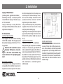
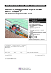
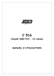
INSTALLATION, OPERATION AND MAINTENANCE INSTRUCTIONS
KESSEL – Wastewater Station Aqualift® F for floor-slab installation
for wastewater with or without sewage.
Article # 28300 / 28330 / 28350
Product Advantages
Upper section telescopically height adjustable, rotatable and tiltable.
Adjustment of cover to the tile grid
Compression seal flange for attachment of vapour barrier
As a double-lifting station for increased wastewater demand
Z-53.2-484
Abb. zeigt Art.-Nr. 28300
Installation
Service
of this unit should be carried out by a licensed professional servicer:
Company / Telephone No.
Edition:
2010/02
Number:
298-057EN
Subject to technical amendments
Safety Instructions
This instruction handbook contains important security advices which must be followed at all times during installation, operation,
maintenance and repair of the power unit. The security advices are labelled as follows.
General warning sign according to ISO 3864-B-3-1 tagging endangering of persons.
Caution
Warning sign according ISO 3864-B-3-6 to caution against voltage.
This word indicates security advices, disregarding these will cause severe danger for the station and itʼs function.
This instruction handbook must be available at all times in the station.
Dear customer,
We are happy, you decided to choose a product made by KESSEL.
Before leaving the factory the whole station has been subject to a strict quality control. However, we kindly ask you to check whether
the station has been delivered completely and without any damage. In case of transport damage, please look for the regulations in
chapter „guarantee“ of this instruction.
Prior to installation and putting into operation of the Aqualift – it is in your interest - and essential that you carefully read and follow the
installation-, operation-, maintenance- and repair instructions.
KESSEL AG
Safety Instructions
General Precaution
For installation, operation, maintenance or repair purposes of the station, all regulations for accident prevention must be followed. DINand VDE-Standards and
guideline specifications as well as regulation of the local energy supply- and utility undertaking must be carefully followed.
Staff Qualification and Staff Training
The staff for operation, maintenance, inspection and installation must possess appropriate qualification for carrying out these operations.
Reponsibility, competence and supervising of staff must be exactly arranged by the operator. In case staff doesnʼt possess the necessary know-how, a training- and an instruction unit must be executed for staff. By order of the operator of the pump station the producer/supplier will execute this training if necessary.
Furthermore, the operator has to assure, that the content of the manual is fully understood by the staff. Herewith, an instruction record
must be kept.
Danger caused by voltage
This station contains voltages and controls rotating, mechanicals parts of the station. Disregarding the instruction handbook may result in
major property damage, injury or even fatal accident.
Prior to all works at the unit, it must be disconnected from the power supply system network. Main switch and cut-outs must be disconnected
which means a de-energized connection and protection against a restart.
Do cut-outs exist, these must be disconnected and indicated with a reference note, so third party is not able to restart the main fuse.
The VDE 0100 applies to all works at the electrical unit.
The unit provided with a earth fault circuit equipment equipped with a design error current of not more the 30 mA.
Do not open the switching tool as it is under voltage. Only skilled personnel for electro is allowed to execute work at the electrical equipment. VDE 0105 gives a definition what is to be considered as a skilled person for electro according to the regulations.
It must be guaranteed that all parts of the electrical unit are in perfect condition. In case of damage the unit should not be put into operation by no means and respectively switched off immediately. Electrical wires should be installed so they cannot be buckled and are nontensioned.
Safety Instructions
Possible risk of burns for Hands and Fingers
During operation the prime mover may develop a high temperature.
The pumps are equipped with an exterior cutter. Functional requirement does not include any shielding. Therefore, do not stay in danger
zone of rotating parts and allow sufficient safe distance. Do not reach into the cutter head or suction area of the pump. Working on the
pump is only allowed while the electricity is disconnected and moving parts have fully stopped rotating. Pump should only be put into operation in installed condition and not outdoor. During maintenance- and repair work consider the sharpness of the edges.
Danger of heavy weight/stability of unit parts
Hold the pump only at the handle and slowly discharge it into the ready mounted construction hole. Caution with the parts while lifting and
mounting.
Dangerous to Health/Personal Protective Equipment
The effluent unit delivers fecal wastewater containing substances which might be dangerous to health. Avoid any direct contact of wastewater or contaminated unit parts with eyes, mouth or hands while working at the unit. In any case of direct contact, the corresponding body
part must be immediately carefully washed and as the case may be disinfected.
Furthermore, the atmosphere in the construction hole may be dangerous to health.
Switch on/Start off operation of the pump
Prior to operation check the conditions on-site
•
•
Avoid dry running the pump!
Do not allow the machine running in dry run or slurping operation at any time, that is cutter equipment,
rotor disc and pump box must be flooded until minimum submersion depth at all times.
The pump builds up a discharge pressure overpressure.
Table of Content
1. General
2. Installation
3. Operation
4. Treatment/Maintenance
5. Specifications
6. Assistance in case of failure
7. Accessoiries/Spare Parts
8. Guarantee
1.1
1.2
Use ................................................................................................... page
Description of Unit............................................................................. page
6
6
2.1
2.2
2.3
2.4
2.5
2.6
Installation in floor slab .....................................................................
Deepened installation into the floor slab ...........................................
Connectors .......................................................................................
Installation of Pump ..........................................................................
Installation into pressurised water ....................................................
Installation recommendation.............................................................
page
page
page
page
page
page
7
7
8
9
10
11
4.1
4.2
4.3
4.4
4.5
Removal............................................................................................
Installation.........................................................................................
Maintenance .....................................................................................
Maintenance with integrated backwater valve ..................................
Removal of pressure sensor .............................................................
page
page
page
page
page
12
12
12
13
13
........................................................................................................................ page
16
........................................................................................................................ page
5.1
5.2
Scale Drawings................................................................................. page
Performance Diagrams ..................................................................... page
....................................................................................................................... page
........................................................................................................................ page
12
14
15
17
18
1. General
1.1 Application
This system is designed for pumping wastewater with or without raw sewage. Important is that sufficient water is always available - pressing the 'water savings' flush on
toilets is not recommended.
Important!
The KESSEL Aqualift F Wastewater
Station is not for use with flammable or explosive liquids. The system should only be
used for the macerating of sewage, toilet
paper and gray water. The warranty of this
product does not include damage to the system caused by the pump intaking bandages, tampons, cotton swabs, razor blades,
moist towels, cotton, hair, sponges, plastic
bags, washclothes, diapers or other objects. The pumping of solvents and thinners is
also not allowed. It is recommended that the
warning sticker shown below is placed in the
proper visible area to prevent improper
items entering the drainage system. Condensation fluids from furnaces / heaters
should be neutralized or adequately diluted
with water.
1.2 System Description
The KESSEL Aqualift F Wastewater Station
is a lifting station with an unmatched power
to size ratio. Through the use of high end,
permanently resistant plastics, the system is
able to handle household acids and bases
(ph value from 6.5 to 10) as well as cold and
hot water (up to 95 deg C for short periods).
The lifting station consists of a pump with
non-return flap, quick release flange
6
connection, vertically adjustable upper section and a 300 kg rated tileable cover with an
integrated odour free floor drain. For deeper
installations in floor slabs, the extension
section (Article Number 83071) should be
used. KESSEL recommends the connection
of a closure valve to the outlet pressure pipe
of the system.
The Aqualift F Wastewater Station is available in three models:
- single pump with float switch
(Article Number 28300)
- single pump with SDS control unit
(Article Number 28350)
- twin pumps with SDS control unit
(Article Number 28330)
2. Installation
Important:
Pump station is to be installed in frost-free
and dry area. Do not immerse cable ends
into the water while installation and mounting. Electrical plug connection is to be
protected from moisture. In case of flooding danger the mounting of the electrical
plug connection should be executed in an
area where there is no danger of flooding.
Prior to installation of KESSEL pump stationtion Aqualift® F, all parts must be
checked upon loss during transport.
CAUTION: After final adjustment cut-outs
have to be fixed at the upper section especially in the area of cable bushing and
where additional inlets were added (picture 3).
2.1 Installation in slab:
The pump box is to be levelled up horizontally on a granular subbase.
Insert the enclosed rubber gasketed seal into
the recessed gasket area, grease it and
mount the upper section. The telescopically
upper section allows a continously variable
adjustment of the pump station Aqualift F into
already existing installation depth. Ground
falling gradient can be levelled out until up to
5°. An adjustment of the cover, p. e. the tile
pattern is possible (picture 2).
After successful water proof check of all existing piping the vessel can be poured into concrete bed.
3
2
7
2.2 KESSEL-Pump Station Aqualift® F for
depressed installation into the slab
(with extension Article # 83070)
Depending on installation depth one or two extensions between upper section and connector may be used. The gaskets are to be greased accordingly. Thereby the drain pipe must
be shortened according to the level adjustment.
Installation of covers with selectable surface:
For the covers with choice of surface there is
the possibility of fixing tile flooring or natural
stone into the cover. This way you can fit the
flooring to the room. For tile fixing we recommend products by PCI, Schomburg, Deitermann. To achieve an unproblematic workmanship we recommend the following:
2. Installation
Laying of Natural Stone:
(marble, granite, agglomerated marble)
Grounding of slab p. e using PCI ground
varnish 303. For laying of the slabs use p.
e. PCI-Carrament.
Laying of the slab, p. e. using PCI-Carrament (special Natural Stone silicion) area of
application analogue to 1.
2.3 Connections
a) off-set inlet-connection
Fully equipped connection socket according
to DIN 100 available. The inlet-piping must
be installed allowing a minimum of 2 % falling gradient.
Attention: Do not drill the vessel.
Improper drilling may cause damage of the inner vessel which may
cause leakiness of the pumping equipment.
b) drainage connection
The installation of the drainage connection is
only possible after installation of pump according to the instruction in point 2.4. The connec-
tion of the drainage function to the sump is executed through the attached drainage connection. Insert the drainage connection into the
pre-setted wall chase and lock it with the
single-hand quick-release fastener.
Using a stormwater tight cover plate (auxiliary
equipment) the wall chase must be closed
using the provided sealing plug.
Depending on the inlet depth (mortise depth of
upper section) the drainage connection can be
trimmed to the particular length (see picture
No. 3).
c) pressure conncection
Pressure connection: 1 ½“ male thread
The pressure pipe set (Article No. 28 040)
includes a 5 m pressure pipe tube DA 40
and an adapter with a pipe clamp. Alternatively a pressure pipe diameter=40 mm minimum 38 mm can be used for the PVC-adhesive bond. The delivery pipe has to be
guided via the local defined backwater level
and connected to a ventilated groundcollecting line.
8
3
d) cable conduit access
For installation of the electrical lines and if necessary of the air tube for the pressure sensor a cable conduit on site must be provided
(see picture No. 4). The empty conduit can be
installed in the provided cable bushing which
is located in the connector. To avoid condensation water the cable conduit must not be
sealed air-tight.
2. Installation
ded across the roof.
A fixture access is
provided. This is
sealed by a socket
plug. Remove it for
installation purposes. For the Tronicoption it is recommended to install
the optical sensor
prior to the installation of the fixture
vent.
whether the sewage station is free of solid
contamination and building material. Whereas this is not the case the complete equipment is to be cleaned. Prior to installtion cleaning of all sealed surfaces is essential. Insert
the pump into the pump slab and fix it with the
help of the two lock staples (safety hook). Fix
and lock the rotatable connection with the
one-hand-fastener (see picture 5). Assure a
back-up of 1 m minimum for the length of the
tube for installation to allow to lift out the
pump and put it on the tile flooring for maintenance service.
2.4 Installation of the pump:
To avoid damage during transporting the
pumps are packed separately. Check
a) Aqualift® F Mono with float
After installation the float has to be inserted
into the separate opening. Pull the cable together with the plug through the cable conduit. The unit is ready for operation as soon
as the power supply is available.
e) Ventilation vent
Ventilation vent shall be provided at all
times.
A ventilation pipe must be installed with this
system. For this pumping system it must be
installed at a minimum of a nominal width DN
70. To avoid unpleasant odour it must be gui-
4
Ventilation
The venialtion tube must be installed with a constant increasing slope to the control unit.
max. deepth 4 cm
f) Alarm device
For installation of the float switch version the
alarm device is strongly recommended. Herewith, failures during operation will be indicated, p. e. an increased water level caused by
failure of the pump. In addition a remote control signaller must be installed.
9
Caution: Check after installation
whether the pump is mounted stationary. As there are existing two versions, please follow further proceedings.
2. Installation
b) Aqualift® F Tronic/Duo
Pull the transparent tube of the already installed pressure sensor through the cable
5
conduit. Pay attention to a unbuckled and
permanent rising of installation. In addition
the optical sensor (alarm device) is to be inserted into the designated opening. Hereby
the purple sealing plug is to be removed.
The Tronic version is ready for operation as
soon as the cables are connected to the control unit according to the instructions given in
the manual.
Refill the vessel with water and proof check
the functions of the floating switch respectively the pressure sensor.
2.5 Installation in concrete slabs subject to high groundwater / moisture
(gasket set Article Number 83023)
In case of installation in concrete slabs subject to high groundwater / moisture the KESSEL wastewater pumping station can be easily and unproblematically sealed. Herewith a
seal sheeting is clamped between the counterflange made of polymer and at the integrated compression seal flange of the carrier
and bolted with the attached screws. Any on
site used sealing foil is acceptable. For installation into a water resistant sump pan
KESSEL offers an additional matching sealing sheet made out of natural latex material
with counterflange. Here, the drill-holes for
bolting are already stamped out. (Article
Number 83023, see picture 6).
If it is necessary to make an opening for example into the concrete sump pan for the access of the inlet, cable conduit access and so
10
on these interpenetrations must be executed
so watertightness is guaranteed.
counterflange
Gasket set
(83023)
seal sheeting
6
compression
seal flange
2. Installation
2.5 Installation with moisture connection
seal (Sealing set Article Nu. 83023)
In the case that this system is installed in a
foundation slab which is protected by a full
surface moisture membrane to protect
against groundwater or high moisture, the
connection flange system (Article Nu. 83023)
should be used. The on-site moisture membrane should be connected to the integrated
body flange on the Aqualift F and then fixed
in place with the 83023 plastic perimeter
flange (connection screws are included). In
the case that a waterproof concrete foundation slab is used, the NK/SBR heavy duty
sealing membrane (included in 83023)
should be connected between the integrated
body flange and the flange supplied with the
83023 - the sealing membrane has pre-drilled holes to fit perfectly onto the integrated
flange. In the case that this water proof slab
needs to be penetrated for inlets or conduit
pipes, each of these penetrations should be
properly sealed against groundwater / moisture.
Illustration (showing Pumpfix F backwater
valve)
Installation shows concrete slab with full surface
moisture membrane
Tiles
Fliesen
Screed
Estrich
S
Insulation
Dämmung
Concrete
slab
Betonboden
Protective
concrete layer
Schutzbeton
Abdichtung
moisture
membrane seal
Unterbeton
Base
concrete slab
BWS *
2
3
1
4
Installation shows waterproof concrete slab
Tiles Fliesen
Estrich
Screed
Dämmung
Insulation
F
Betonboden
Concrete
slab
BWS *
4
11
5
2
1
KESSEL Pumpfix F, Staufix FKA, Staufix
SWA or Controllfix
Sealing flange
Article # 83023
Extension section
Article # 83071
Intermediate section DN 100 with stainless
steel pressure sealing flange
Article # 27198
Polymer sealing membrane
Article #27159
2.6 Installation with Extension section
(Article Nu. 83071
When using the extension section, the flange height remains vertically adjustable. If required, the extension section can be shortened on-site by sawing off the appropriate
amount.
2.7 Sound Insulation
To help improve sound reduction of the system, the base of the Aqualift F should be decoupled with the concrete foundation (not
be in direct contact with slab).
3. Initial Operation
Installation recommendation
Backwater level
KESSEL Aqualift F wastewater Station
Alarm unit
Waterproofing set
Outlet set with flexible pressure pipe
Ventilation pipe to roof
Art.# 28300
Art.# 20221
Art.# 83023
Art.# 28040
Attention: The initial operation must be
executed by authorized and qualified personnel. Prior to operation the installation
must be checked accurately. It is absolutely necessary to follow the instructions of the safety regulations in chapter 1 of the instruction handbook at all
times.
Please read this user´s manual for the wastewater
station Aqualift F (for Tronic version). It must be considered that liquid level will not drop beneath minimum ground-level. In addition to the standard operation process the pump will start a weekly selfdiagnosis-run.
12
4. Cleaning and Maintenance
Attention: Prior to working on the
pump DISCONNECT MAIN PLUG!
Follow here all the safety instruction mentioned in chapter 1. Prior to maintenance work the seal housing must be
pumped dry so a blow-out the wastewater
is avoided.
4.1 Dismantling:
By dismantling of the one-hand-fastener and the
two lock staples (safety lever) the pump can be
easily taken out without using any tools. The nonreturn-flap in the pressure joint of the vessel
avoids that the wastewater which still remains in
the discharge pipe (pressure pipe) returns back
to the unit.
4.2 Installation:
Prior to re-installation all sealing faces must be
cleaned. Grease the lip sealing in the drain. Reinsert the pump as described in chapter 2.4.
4.3 Maintenance:
For all works at the pump, a lifting of the pump out
of the unit is recommended as well as to execute a preliminary cleaning of it. Other tasks as described are not allowed to be executed.
The maintenance work should only be executed
by authorized and qualified personnel.
Repairs are to be exclusively executed by the
manufacturer.
General Maintenance:
According to DIN 12056 a maintenance must be
executed by a specialist (specialised company)
in the following time intervals:
• after 3 months for units installed in commercial
businesses
• after6monthsforunitsinstalledinmultifamilyhousings
For single-family houses the maintenance service must be executed after six months.
A visual check of the unit site must be executed.
The unit must be checked regarding sediments
and wearing.
For the following parts a visual check must be
executed, if necessary the parts of the unit must
be cleaned from sediments.
4.4 Maintenance of the integrated backflow flap:
Remove the pump. Slightly open the backflow
flap and therefore allow the water remaining in
the pipe to run back into vessel.
After dismantling the pump fixing (Release of
the recessed-head screw) the backflow flap
13
can be taken out and be cleaned.
This way an unobstructed access for cleaning
of the pressure pipe is possible.
4.5 Withdrawl of Pressure Sensor
Release the air-tube out of the bolting. Check
free pass to the control unit (if necessary remove condensation water).
Disassemble air-tube fixing from pumping slab.
By opening of the one-hand-fastener check for
contamination.
Check pressure sensor: Disassemble air-tube
fixing and dip into a provided bucket. If the
pump is re-activated by dipping the pressure
sensor than the functionality is granted. If this
is not the case please contact immediately our
customer service.
Prior to re-installation of the pressure
sensor into the pumping slab the water
must be pumped out of the sump vessel
otherwise the setting of the switchpoints is not correct.
- cutting unit
- ventilation unit
- pressure access
- pressure sensor
5. Technical Dates
Wastewater Aqualift® F Mono underground single unit with removable pump including floater.
Article # 28300
5.1 Dimensioned drawing:
Wastewater Aqualift® F Tronic underground single unit with removable
pumpe including SDS-switch-unit
(self-diagnosis-system). Article # 28350
+
Wastewater Station Aqualift F Duo
underground double unit with two removable pumps including SDS-switch-unit
(self-diagnosis-system) Article # 28330
14
5. Technical Dates
Maximum delivery
Pumping head
Q (m3/h)
H (m)
Pumping head H (mWS)
5.2 Performance diagram
0,0
8,0
3,0
7,5
5,0
6,8
Delivery (m3/h)
Kind of
current
Voltage
electricity
AC
230 V
5,3 A
motor
performance
speed
mode
protection
P1 / P2
1000 W/
thermal
2800 min-1
S 3 - 30 %
(integrated)
550 W
Allowed ambient temperature 0....50°C
Maximum wastewater temperature up to 40°C
15
6,5
6,0
7,8
5,00
9,0
4,0
10,0
2,8
6. Assistance support in case of Failure
Failure
Pump is not running
Rotor blocked
Possible Reason
Remedial Treatment
no mains power supply
mains cable damaged
defective float-switch or
pressure-control-unit
ventilation pipe clogged
contamination, solid and coarse material are
jammed between rotor and suction
flange
Reduced delivery
wearing of the suction flange
wearing of the rotor/cutting unit
ventilation pipe clogged
Pump is running although no
wastewater is entering system
defective/leaking non-return-flag
pressure switch clogged
defective/blocked float-switch
check main power
check fuse-box
repair only by KESSEL
customer service
check float-switch or pressure (see chapter
4.5) or repair by KESSEL customer service
clean ventilation drilling
cleaning of pump
cleaning of pump
Replace suction basket impeller,
cutting assembly
clean ventilation pipe
exchange non-return-flag
clean pressure-access
inspection of tightness for all parts of the unit
16
7. Auxiliary Equipment / Spare Parts
Position
1
2
3
4
5
6a
6b
7
8
9
10
11
12
13
14
15
Part
400x400mm tileable cover
DN 50 pipe seal
Outlet connection
Upper section 400x400mm (220mm height)
Upper section gasket
Sewage pump with float switch
Sewage pump without float switch
Pump flange gasket
Non-return flap
Pump connection lock
Ventilation pipe (5 meter) – only for Tronic models)
Safety lock
Sensor
Securing lock
Pressure switch – only for Tronic models
Length = 310 mm (models up to March 2010)
Length = 250 mm (models from April 2010)
Odour trap
Battery (2 required) – only for Tronic models
Article number
83055
298-023
298-030
83061
173-028
298-028
298-029
298-017
298-013a
157-004
298-045
243-298
80085
298-034
298-046
298-091
47200
197-081
In the case that the control unit up to model Rev 6.4 is replaced with a new control
unit, the 250mm long pressure switch should be used.
17
8. Guarantee
1. In the case that a KESSEL product is defective, KESSEL has the option of repairing or
replacing the product. If the product remains
defective after the second attempt to repair or
replace the product or it is economically unfeasible to repair or replace the product, the
customer has the right to cancel the order /
contract or reduce payment accordingly. KESSEL must be notified immediately in writing of
defects in a product. In the case that the defect is not visible or difficult to detect, KESSEL
must be notified immediately in writing of the
defect as soon as it is discovered. If the product is repaired or replaced, the newly repaired or replaced product shall receive a new
warranty identical to that which the original
(defective) product was granted. The term defective product refers only to the product or
part needing repair or replacement and not ne-
cessarily to the entire product or unit. KESSEL
products are warranted for a period of 24
month. This warranty period begins on the day
the product is shipped form KESSEL to its customer. The warranty only applies to newly
manufactured products. Additional information
can be found in section 377 and 378 of the
HGB.
In addition to the standard warranty, KESSEL
offers an additional 20 year warranty on the
polymer bodies of class I / II fuel separators,
grease separators, inspection chambers, wastewater treatment systems and rainwater storage tanks. This additional warranty applies to
the watertightness, usability and structural soundness of the product.
18
A requirement of this additional warranty is
that the product is properly installed and operated in accordance with the valid installation
and user's manual as well as the corresponding norms / regulations.
2. Wear and tear on a product will not be considered a defect. Problems with products resulting from improper installation, handling or
maintenance will also be considered a defect.
EC DECLARATION OF CONFORMITY
Electromagnetism Guidelines 89/336/EEC Electromagnetism Guidelines 89/336/EEC
Low Voltage Guidelines 73/23/EEC
Kessel GmbH, D-85101 Lenting
we declare that the product
KESSEL Wastewater Station Aqualift® F for underground installation
for wastewater with or without sewage
is in agreement with
EN 12050-3
EN 12100-1 (2003-11)
EN 60335-2 (1996-09)
EN 61000-6-4 (2002-01)
EN 60730-1
EN 12100-2 (2003-11)
EN 60335-1 (2003-5)
EN 61000-6-1 (2002-1)
EN 809 (1998-11)
Lenting, den 07.03.2007
B. Kessel
A. Kessel
19
Everything for Drainage
Solutions from a single source
Backwater valves and cleanouts
Volatile liquid traps
Lifting stations, pumps, warning
and control units
Rainwater management systems
Grease, starch and oil / fuel
separators
Inspection chambers
Custom projects for industrial
applications
Polymer pipe fittings
Stainless steel drains and
channels