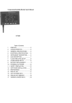
1
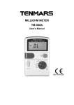
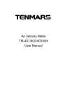
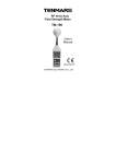
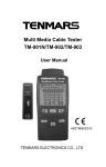
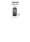
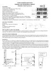
Temperature/Humidity Monitor TM-185 TM-185D User’s Manual HB2TM1850000 TM-185/TM-185D Table of Contents 1 PREFACE ......................................................... 2 2 CHARACTERISTICS ........................................ 2 3 GENERAL SPECIFICATIONS .......................... 3 4 ELECTRICAL SPECIFICATION........................ 4 5 INSTRUMENT DESCRIPTION.......................... 5 6 LED DESCRIPTION.......................................... 8 7 CLOCK AND DATE SETUP .............................. 9 8 ALARM RANGE SETUP ................................. 10 9 BATTERY REPLACEMENT ............................ 12 10 EXTERNAL DC POWER ................................ 13 11 SAFETY PRECAUTION .................................. 13 12 SOFTWARE INSTALLATION (TM-185D) ........ 14 13 MAINTENANCE .............................................. 17 14 END OF LIFE .................................................. 18 15 AUTO STORES DATA .................................... 18 16 SINGLE DATA MEMORY ................................ 19 17 VIEWING LOGGED DATA .............................. 19 1 TM-185/TM-185D 1 PREFACE Thank you for your patronage, please do read the operation instructions in details before you use this meter, so that operate correctly, make a machine give play to the best function. 2 CHARACTERISTICS LED display. It shows both the value of temperature and humidity. It give the selection of °C or °F. Real time data. Data Hold function. Alarm function. 2 TM-185/TM-185D 3 General Specifications Display: Double rows LED, humidity MAX reading 999,and temperature MAX reading 1999. Temperature sensor: Diode. Humidity Sensor: Capacitor Sensor. Sampling: 1 times/second. Power: AC to DC Adapter. (9V/1A). Backup Power:9V battery、 NEDA 1604、IEC 6F22 or JIS 006P(Only data logger use). Resolution:0.1%RH,0.1°C,0.1°F. Size:260x178x47mm(LxWxH). Weight: 1000g. Operating Temperature and Humidity: -20°C ~ +60°C, <95% RH. (Non-condensing). Storage Temperature and Humidity: -10 to 60°C, <70% RH. (Non-condensing). Consumption Current:≦700mA. Standard Accessories:User’s manual, 9V battery, AC to DC Adapter, Carrying case,LCD Wall Mount. TM-185D Accessories: Datalogging Box. (Datalogging capacity with Memory Size:30,000 data sets). MINI USB 4P(MALE) to USB A Type cable. Install CD disk of TM-185D . 3 TM-185/TM-185D 4 Electrical Specification Measurement Range: Humidity: 5%~95%. Temprature:-20.0°C~60.0°C /-4.0°F~140.0°F. Temperature Accuracy:±1.0°C/±1.8°F (-5.0°C ~40.0°C /23°F~104°F);other ±2.0°C /3.6°F. Humidity Accuracy: ±2.5%RH(at 25°C,10%RH~90%RH). ±5.0%RH(at 25°C,<10%RH,>90%RH). Note1: If you require more accurate we can do it according to your requirement. Note2: When the AC adaptor is off will start the backup power only to provide Data Logger use, the LED won’t be lightened. Note3: Datalogging operation instruction at Install CD disk of TM-185D. 4 TM-185/TM-185D 5 Instrument description 5 TM-185/TM-185D 6 TM-185/TM-185D 1. 2. 3. 4. 5. 6. 7. 8. 9. 10. 11. 12. 13. Temperature & Humidity sensor Time Set Button Alarm Set Button °C /°F Set Button/Down Button Enter Button Hold Button/UP Button LED Display Data Logger Box (optional) Data Logger Box interface (-) Power Switch Terminal Blocks (Always off) Audio Output 15. 16. 17. 18. 19. 20. ARM Hold Battery Cover. Record Button Memory Button USB interface Data Logger Box interface (+) Lo Battery LED Display 14. External power DC 9V 7 TM-185/TM-185D 6 LED description 1. 2. 3. 4. 5. 6. 7. 8. 9. 10. Temperature reading value Humidity reading value Time reading value Time unit Data logger symbol Temperature unit Alarm symbol HI symbol LO symbol Humidity unit 8 TM-185/TM-185D 7 Clock and Date setup Push “ setup. Push “ Push “ digit. ” button into time clock and date ”button to select option to adjust ”or “ ” button to change the Push “ ” button to store the setup then exit the mode, If not push “ ” button then exit clock and data setup. This meter clock to introduce 12 hour time, if you want change 24 hours, push” ”. 9 TM-185/TM-185D 8 Alarm Range Setup Push “ ” button into alarm setup LED will display ALARM ON。If you just reading alarm setup please push “ ” button again LED will display ALARM OFF. First push “ ” button into alarm range setup,LED display show “ LO ALARM ON °C or °F ”,and set LOW alarm Temperature, Push “ ”or “ ” button to change the digit. Second push “ ” button into alarm range setup,LED display show “ HI ALARM ON °C or °F”,and set Hi alarm Temperature, Push “ ”or “ ” button to change the digit. Third push “ ” button into alarm rang setup, LED display slow “ LO ALARM ON %RH”, and set Hi alarm Humidity, Push “ ”or “ ” button to change the digit. Fourth push “ ” button into alarm range setup, LED display show “ HI ALARM ON %RH”, and set Hi alarm Humidity, Push “ ”or “ ” button to change the digit. If you want to store this setup push the “ button, If not push “ ” button then exit alarm setup. 10 ” TM-185/TM-185D If test Temperature or Humidity exceed set range, buzzer were bleep, at this time socket output sin wave signal at 2000Hz,terminal blocks were short. 11 TM-185/TM-185D 9 Battery replacement WARNING If the LO Battery LED were turn on, please replace the battery immediately Turn off the instrument. Open the battery cover and remove the battery. Replace with four-9V NEDA 1604, IEC 6F22 or JIS 006P size battery. Install the battery cover. 12 TM-185/TM-185D 10 External DC Power External AC to DC adapter: Voltage 9VDC(8~14VDCMax) Socket:pin Positive, Ground Casing External Diameter 6.3mm internal Diameter 2.0 mm 11 Safety Precaution For cleaning the instrument use a soft dry cloth. Never use a wet cloth, solvents or water, etc. Datalogging capacity with Memory Size:500 data sets Operation Altitude: Up to 2000M. Operating Environment: Indoors use. This instrument has been designed for being used in an environment of pollution degree 2. 13 TM-185/TM-185D 12 Software installation (TM-185D) Please put the CD in the PC that will be connected to this meter. Please select the USB driver that will be installed, such as E:\TM-185D\PL-2303 Driver Installer.exe (windows 2000 SP4/windows XP SP2), click twice on the left key of the mouse to install the USB driver. 14 TM-185/TM-185D Select the SETUP.EXE i.e., E:\TM-185D\SETUP.EXE and installs the desktop icon Tack out the CD from PC after completed the installation of the desktop icon. 15 TM-185/TM-185D Use the USB cable to connect the meter and computer according to the drawing. Select the desktop icon (TM-185) and click twice on left key of the mouse to run the procedure. 16 TM-185/TM-185D 13 Maintenance Do not use the meter in an environment with severe change; do not store the unit in an environment with high temperature, high humidity, and high vibration Take battery off if the meter has not been used for a long period of time The Diode temperature probe is used to measure temperature and the capacitive humidity sensor is used to measure take humidity The thermocouple and humidity sensor will start aging under the influence of oxidation, reduction, corrosion, pollution, vaporization, diffusion or other metallurgy. The aging process will affect its precision seriously. Cleaning and inspection of temperature probe: The smoke, coal, dust, grease attached on the protective tube of temperature probe will slow down the heat conduction of the thermocouple and cause measuring error. Therefore, it should be cleaned periodically. The metal coating of thin thermocouple should be replaced properly upon the occurrence of corrosion. Cleaning and inspection of humidity sensor: The smoke and dust attached on the humidity sensor will slow down the function of humidity sensor and cause measuring error. Therefore, it should be cleaned periodically. Blow off the dust with mild compressed air instead of water or alcohol. The aluminum plate inside the humidity sensor should be replaced upon the occurrence of corrosion. 17 TM-185/TM-185D 14 End of life Caution: this symbol indicates that equipment and its accessories shall be subject to a separate collection and correct disposal 15 Auto Stores Data Push “ ” button into time clock and date setup. Push “ ” button again into auto stores time clock setup. This time LED display show auto stores data time,you can push to change time unit (Max auto stores data time :23hour 59min 59sec) Push “ ”or “ ” button to change the digit. If you want to store this setup push “ ” button, If not push “ ” button then exit auto stores data time setup. If stores data will be writhing into memory LED display show Record on 18 TM-185/TM-185D 16 Single data memory Push Record button (in TM-185D) each time to store the display reading and memory location in memory. 17 Viewing logged Data Push Memory button (in TM-185D) into view logged data mode,push Memory button again exit view logged data mode ” In view logged data mode push“ button reading stores time ,push “ button to change the temp unit,Push “ ”or “ ” button to change view logged data 19 ” TENMARS ELECTRONICS CO., LTD 6F, 586, RUI GUANG ROAD, NEIHU, TAIPEI 114, TAIWAN. E-mail: [email protected] http://www.tenmars.com