1
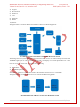
International Journal of Advanced Technology in Engineering and Science www.ijates.com Volume No.02, Issue No. 12, December 2014 ISSN (online): 2348 – 7550 EXCAVATOR MONITORING SYSTEM USING SMART PHONES S.L.Chavan1, Shivtej V. Yadav2, Shravan K. Tarange3, Sandip O. Patil4 1 Assistant professor, Department of Electronics & Telecommunications, JSPM’s Rajarshi Shahu College of Engineering, Pune, (India) 2,3,4 UG Student, Department of Electronics & Telecommunications, JSPM’s Rajarshi Shahu College of Engineering, Pune, (India) ABSTRACT This paper is proposed a method for monitoring the excavator parameters using smart phones. These excavator systems are very huge, heavy and they requires large amount of investment. These excavator systems should be handled properly so that they can remain well maintained. Another problem is that peoples which are owners of these machines are having more than one machine. So while working of these machines, it is not possible that the owner of those machines will be present at both machines at a time and he is not able to supervise the handling of excavator system by driver or his labor. Many times labors working at these systems are not loyal with their boss. Also sometimes they stole fuel from the tanks of excavator system and sell that outside and earn money. The paper represents the method to prevent the above possibilities with help of electronic equipments. The paper begins with presenting background theory in microcontroller, different IC’s, sensors and ANDROID application as they apply to the project. In the conclusions are given discussions of design results. Keywords – Excavator, Fuel Level, Bluetooth Interfacing, ANDROID Application, LCD & Keypad Ι. INTRODUCTION Excavators are heavy construction equipment consisting of a boom, stick, bucket and cab on a rotating platform. Excavator systems are used for various purposes in constructions like Digging of trenches, holes and foundations, Forestry work, Demolition, Drilling shafts for footings and rock blasting.Due to large cost of machineries, their safety also important and these excavator systems should be handled properly so that they can remain well maintained. Another problem is that peoples which are owners of these machines are having more than one machine. So while working of these machines, it is not possible that the owner of those machines will be present at both machines at a time and he is not able to supervise the handling of excavator system by driver or his labor. Many times labors working at these systems are not loyal with their boss. They work more for customer without informing to owner on the money of owner and earn more money and remain dishonest with owner of excavator. Also sometimes they stole fuel from the tanks of excavator system and sell that outside and earn money. Because of this attitude or behavior of driver, the owner of excavator system faces to loss instead of profit even investing large amount of money in his business. Other parameters are also responsible for losses of owner of excavator system like rough handling of excavator may leads to rise in the temperature of oil and that can results to damage of machinery, sometimes these machines get stolen by thieves and leads to shutting down of business. A Bill calculation is one of the main problems between owner and customer. Many time conflicts happen between customers and owner. This may also cause reduction in number of customers which is not good 490 | P a g e International Journal of Advanced Technology in Engineering and Science www.ijates.com Volume No.02, Issue No. 12, December 2014 ISSN (online): 2348 – 7550 for the business. This regular problem of these owners gives idea to us to implement an electronic system which will solve these problems and satisfy the owners of excavator. So we are solving almost all problems with the excavator. II. RELATED WORK 2.1 Problem Description After insertion of key in excavator machine the Excavator Monitoring System become on. Then after entering the password through the keypad the excavator system get ignited. As soon as machine starts, the message from monitoring system goes to owner of that excavator. At same time, timer should be starting to count the time required for the work or task. During this happening the fuel level is indicated on LCD for drivers understanding and current level of fuel, oil temperature etc. parameters are sent on the application developed on smart phone of owner. For real time, we are interfacing the real time clock IC with system, so that we will get the exact time wise status of machine. For safety purpose, we are also showing the current location of that machine with help of GPS facility. After completion of the work, the system will calculate the bill amount and send it on mobile of owner. Components used: 1) FUEL LEVEL SENSOR 2) PT 100 3) LPC2138 4) Keypad. 5) LCD 6) MAX 232 7) HC-05 8) 7805 9) LM1117 2.1.1 Fuel Level Sensor Level sensor also called as fuel/petrol gauge is used in auto mobile industry to measure the level of fuel in vehicle. It operates on variable resistance principle. As the movement of float of the sensor takes place its resistance varies accordingly [1]. The change in resistance is in the range of 1 Ohm to 100 Ohms. By connecting resistor of 100 Ohms in series with this level sensor we can create voltage divider circuit. 2.1.2 PT 100 Pt100 is the common abbreviation for the most common type of resistance temperature sensor used in industry. It has a specified resistance of 100.00 ohms at 0°C and is made of Platinum which has an accurately defined resistance vs. temperature characteristic. There are two minor variations, the most common giving 138.50 ohms at 100°C (DIN standard) and the other giving 139.00 ohms at 100°C. Because accurate tables of resistance v. temperature are available it is common practice to calibrate instruments using precision decade boxes from table values.Pt100 sensors were originally made with platinum wire wound on a ceramic former but are now made more cheaply by depositing a platinum film onto a ceramic substrate. Typical accuracies are 0.2%, 0.1% and 0.05% of value at 0°C. The higher the accuracy the higher the price. 491 | P a g e International Journal of Advanced Technology in Engineering and Science www.ijates.com Volume No.02, Issue No. 12, December 2014 ISSN (online): 2348 – 7550 Note that there are two error characteristics, an offset error (i.e. how far out it is at 0°C) and a span or gain error. The gain error depends on the offset error and the impurities in the platinum. These sensors are also made in 200, 500, and 1000 ohms values. Although the sensors are sold loose, it is usual to buy them made up into stainless steel probes for insertion into processes. 2.1.3 LPC2138 LPC 2138 is hart of Excavator Monitoring System using Smart phone. It controls all subunits of monitoring system. The LPC2138 microcontrollers are based on a 32 bit ARM7TDMI-S™ CPU with real-time emulation and embedded trace support, that combines the microcontroller with 512 kB of embedded high speed Flash memory [5]. Due to their tiny size and low power consumption, these microcontrollers are ideal for applications where miniaturization is a key requirement, such as access control and point-of-sale. The features of ADC 0831 are as following: 32-bit ARM7TDMI-S microcontroller in a tiny LQFP64 package. 32 kb of on-chip static RAM and 512 kb of on-chip Flash program memory. 128 bit wide interface/accelerator enables high speed 60 MHz operation. In-System/In-Application Programming (ISP/IAP) via on-chip boot-loader software. Single Flash sector or full chip erase in 400ms and programming of 256 bytes in 1 ms. Two (LPC2138) 8 channel 10-bit A/D converters provide a total of up to 16 analog inputs, with conversion times as low as 2.44 s per channel. Single 10-bit D/A converter provide variable analog output. (LPC2132/2138 only) Two 32-bit timers/counters (with four capture and four compare channels each), PWM unit (six outputs) and watchdog. Real-time clock equipped with independent power and clock supply permitting extremely low power consumption in power save modes. Multiple serial interfaces including two UARTs (16C550), two Fast I2C (400 Kbit/s), SPI™ and SSP with buffering and variable data length capabilities. Vectored interrupt controller with configurable priorities and vector addresses. Up to 47 of 5 V tolerant general purpose I/O pins in tiny LQFP64 package. Up to nine edge or level sensitive external interrupt pins available. 60 MHz maximum CPU clock available from programmable on-chip Phase-Locked Loop (PLL) with settling time of 100 microseconds. On-chip crystal oscillator with an operating range of 1 MHz to 30 MHz Power saving modes include idle and Power-down. Individual enable/disable of peripheral functions as well as peripheral clock scaling down for additional power optimization. Processor wake-up from Power-down mode via external interrupt. 2.1.4 Keypad At the lowest level, keyboards are organized in a matrix of rows and columns. The microcontroller accesses both rows and columns through ports. 4x4 keypad matrix connected to two ports [5]. The rows are connected to an output port and columns are connected to an input port. 492 | P a g e International Journal of Advanced Technology in Engineering and Science www.ijates.com Volume No.02, Issue No. 12, December 2014 ISSN (online): 2348 – 7550 2.1.5 LCD LCD stands for Liquid Crystal Display. It interfaced with microcontroller to information in alpha-numeric form for user friendly. The system status and battery voltage are displayed on an LCD based on HD44780 controller. The backlight feature of the LCD makes it readable even in low light conditions. The LCD is used here in 4-bit mode to save the microcontroller‟s port pins. Usually the 8-bit mode of interfacing with a microcontroller requires eleven pins, but in 4-bit mode the LCD can be interfaced to the microcontroller using only seven pins. 2.1.6 MAX 232 The MAX232 converts from RS232 voltage level to TTL voltage levels and vice-versa. One advantage of the MAX232 chip is that it uses a +5V power source which is the same as the source voltage of 89C55. In other words with a single +5V power supply we can power both the 89C55 and MAX232 with no need for dual power supplies that are common in older systems. MAX232 requires four capacitor between 1uF to 22uF. The most widely used value for this capacitor is 22uF. The voltage levels of RS 232 are not suitable for microcontroller and hence the buffer IC is used which is MAX 232. The voltage levels of MAX 232 are 0 to +5 volts. The MAX 232 is TTL to CMOS converter and also CMOS to TTL converter and thus making the system compatible with PC. The features of IC MAX232 are as given below TTL to RS 232 Converter. VCC = 5V. Two sets of line drivers. Max 232 requires four external capacitors of value 22 uF. 2.1.7 HC-05 Bluetooth module HC-05 is a class-2 Bluetooth module with Serial Port Profile, which can configure as either Master or slave. a Drop-in replacement for wired serial connections, transparent usage. You can use it simply for a serial port replacement to establish connection between MCU, PC to your embedded project and etc. The features of IC HC-05 Bluetooth module are as given below Bluetooth protocol: Bluetooth Specification v2.0+EDR Frequency: 2.4GHz ISM band Modulation: GFSK(Gaussian Frequency Shift Keying) Emission power: ≤4dBm, Class 2 Sensitivity: ≤-84dBm at 0.1% BER Speed: Asynchronous: 2.1Mbps(Max) / 160 kbps, Synchronous: 1Mbps/1Mbps Security: Authentication and encryption Profiles: Bluetooth serial port Power supply: +3.3VDC 50mA 2.1.8 7805 This is 3 terminal fixed voltage regulator used to convert high DC voltage into constant voltage of 5V.The features of 7805 are as following Output current in excess of 1A. Internal thermal overload protection. 493 | P a g e International Journal of Advanced Technology in Engineering and Science www.ijates.com Volume No.02, Issue No. 12, December 2014 ISSN (online): 2348 – 7550 No external components required. Output transistor safe area protection. Internal short circuit current limit. Available in the aluminum TO-3 package. 2.1.9 LM1117 The LM1117-N is a series of low dropout voltage regulators with a dropout of 1.2V at 800mA of load Current. It has the same pin-out as Texas Instruments industry standard LM317. The LM1117-N is available in an adjustable version, which can set the output voltage from 1.25V to 13.8V with only two external resistors. In addition, it is also available in five fixed voltages, 1.8V, 2.5V, 2.85V, 3.3V, and 5V. The LM1117-N offers current limiting and thermal shutdown. Its circuit includes a zener trimmed band gap reference to assure output voltage accuracy to within ±1%. The features of LM1117 are as following Available in 1.8V, 2.5V, 2.85V, 3.3V, 5V, and Adjustable Versions. Space Saving SOT-223 and WSON Packages Current Limiting and Thermal Protection Output Current 800mA • Line Regulation 0.2% (Max) • Load Regulation 0.4% (Max Temperature Range LM1117-N: 0°C to 125°C LM1117I: −40°C to 125°C 2.1.10 Features The Excavator Monitoring System using Smart Phones are having following features:1) Password protected ignition of system. 2) Oil temperature sensing. 3) RPM counting. 4) Fuel level sensing. 5) Continuously parameters display on smart phone. 6) Location of machine. 7) Automatic bill calculation. 8) World wide application. III. PROPOSED ARCHITECTURE Up till now we had just seen the problem description. Now we will see the proposed architecture of Excavator Monitoring System using Smart Phones. There are mainly 9 blocks in Excavator monitoring system using Smart phone. The fig.1 and fig.2 represents the proposed block diagram of transmitter and receiver of our project Excavator monitoring system using Smart phone. These 9 blocks at transmitter side are as following 1) Fuel level sensor. 2) RPM counter. 3) Oil temperature sensor. 494 | P a g e International Journal of Advanced Technology in Engineering and Science www.ijates.com Volume No.02, Issue No. 12, December 2014 ISSN (online): 2348 – 7550 4) Keypad. 5) Microcontroller 6) MAX 232 7) LCD 8) Bluetooth. 9) Mobile 10) Internet. The figure below shows block diagram of transmitter of Excavator Monitoring System. Fig.1 Block Diagram of Transmitter of Excavator Monitoring System The message sent from system travels over internet and received at receiver side. Then with help of JAVA based ANDROID application we will process the message and it will display on the smart phone.There are 3 main blocks at receiver or owner side. These blocks are as following 1) Internet 2) Smart Phone 3) ANDROID application. Internet plays vital role in communication between the transmitter and receiver over a worldwide. The figure below shows block diagram of receiver of Excavator Monitoring System. Fig.2 Block Diagram of Receiver of Excavator Monitoring System 495 | P a g e International Journal of Advanced Technology in Engineering and Science www.ijates.com Volume No.02, Issue No. 12, December 2014 ISSN (online): 2348 – 7550 Excavator Monitoring System using Smart Phone will start monitoring the parameters of excavator system continuously as soon as it starts. It will reduce the working of owner and he will get all information of excavator from anywhere. This monitoring system will help the owners to raise the profit level and reduce the losses mentioned. After insertion of key in excavator machine the Excavator Monitoring System become on. Then after entering the password through the keypad the excavator system get ignited. As soon as machine starts, the message from monitoring system goes to owner of that excavator. At same time, timer should be starting to count the time required for the work or task. During this happening the fuel level is indicated on LCD for drivers understanding and current level of fuel, oil temperature etc. parameters are sent on the application developed on smart phone of owner. For real time, we are interfacing the real time clock IC with system, so that we will get the exact time wise status of machine. For safety purpose, we are also showing the current location of that machine with help of GPS facility. After completion of the work, the system will calculate the bill amount and send it on mobile of owner. With help of internet he/she will also understand handling of driver, with help of Google map owner can understand the location of excavator. This system can be implemented with low cost and this system also helps to recent manufacturers of excavator to build this system in their current models of excavator systems. IV. CONCLUSION In this paper we studied various components required to build the Excavator Monitoring System using Smart Phones with their important features. We have also studied various operations of Excavator Monitoring System using Smart Phones while using it. By using the Excavator Monitoring System using Smart Phones we can accurately monitor various parameters of the excavator. Also for excavator safety, with help of Google maps we can locate that system. So, system becomes theft free. REFERENCES [1] C. Rojiha “Sensor Network Based Automatic Control System for Oil Pumping Unit Management” International Journal of Scientific and Research Publications, Volume 3, Issue 3, March 2013 ISSN 22503153. [2] P. Harish and Sabariram “Sensor Network based Oil Well Health Monitoring and Intelligent Control” International Journal of Science and Research (IJSR), India Online ISSN: 2319-7064. [3] D. Naresh, B. Chakradhar and S. Krishnaveni “Bluetooth Based Home Automation and Security System Using ARM9” International Journal of Engineering Trends and Technology (IJETT) – Volume 4 Issue 9Sep 2013. [4] Sawant Supriya C, Dr. Bombale U. L. and Patil T. B. „An Intelligent Vehicle Control and Monitoring Using Arm‟ International Journal of Engineering and Innovative Technology (IJEIT) Volume 2, Issue 4, October 2012 [5] Muhammad Ali Mazidi , Janice Gillispie Mazidi , Rolin D. McKinlay, The 8051 Microcontroller and Embedded Sysstems,2nd edition, Eleventh impression, 2012. [6] “ARM7 User manual”, © Koninklijke Philips Electronics N.V. 2005. [7] “MAX 232 Datasheet”, Copyright © 2013, Texas Instruments Incorporated. [8] “78XX datasheet”, National Semiconductor Corporation America, May 2000. [9] “LM1117 Datasheet”, Copyright © 2014, Texas Instruments Incorporated. 496 | P a g e