1
0945_01f.book Page 365 Wednesday, July 2, 2003 3:53 PM
“Do I Know This Already?” Quiz
4.
5.
6.
365
What command brings up an interface that previously was administratively disabled?
a.
no shutdown
b.
shutdown
c.
enable
d.
up
e.
no disable
f.
disable
Imagine that a PC is attached to the same Ethernet as a router. The PC makes a DNS
request for host name Fred, and the PC gets a reply showing IP address 10.1.1.1. What
command could be issued on the router to list the information learned in that DNS
request and reply?
a.
show hosts
b.
show ip hosts
c.
show names
d.
None of the above
Imagine that a neighboring router’s host name is Hannah. Which of these commands
could tell you information about the IOS version on Hannah, without Telnetting to
Hannah?
a.
show neighbor
b.
show neighbor Hannah
c.
show cdp
d.
show cdp Hannah
e.
show cdp interface
f.
show cdp neighbor
g.
show cdp neighbor Hannah
h.
show cdp entry hannah
i.
show cdp neighbor detail
0945_01f.book Page 366 Wednesday, July 2, 2003 3:53 PM
366
Chapter 13: Basic Router Configuration and Operation
7.
8.
9.
10.
What CDP command(s) could identify the model of hardware of a neighbor?
a.
show neighbors
b.
show neighbors Hannah
c.
show cdp
d.
show cdp Hannah
e.
show cdp interface
f.
show cdp neighbors
g.
show cdp entry hannah
h.
show cdp neighbors detail
Imagine that you used a ping command successfully. What messages would have been
sent by the ping command?
a.
ICMP ping
b.
ICMP echo request
c.
ICMP echo management
d.
ICMP query
Imagine that you just erased all the configuration on a router and reloaded it. To
configure the router to use a DNS at IP address 10.1.1.1, which of the following
commands is required?
a.
ip name-server 10.1.1.1
b.
ip dns 10.1.1.1
c.
ip domain-lookup
d.
ip dns-lookup
Imagine that you just logged in to the console of router R1 and then Telnetted to R2.
What must you type to suspend your Telnet connection, going back to R1?
a.
suspend
b.
Ctrl-z
c.
Ctrl-Shift-6, then x
d.
quit
0945_01f.book Page 367 Wednesday, July 2, 2003 3:53 PM
“Do I Know This Already?” Quiz
367
The answers to the “Do I Know This Already?” quiz are found in Appendix A, “Answers to
the ‘Do I Know This Already?’ Quizzes and Q&A Sections.” The suggested choices for your
next step are as follows:
■
8 or less overall score—Read the entire chapter. This includes the “Foundation Topics”
and “Foundation Summary” sections and the Q&A section.
■
9 or 10 overall score—If you want more review on these topics, skip to the “Foundation
Summary” section and then go to the Q&A section. Otherwise, move to the next
chapter.
0945_01f.book Page 368 Wednesday, July 2, 2003 3:53 PM
368
Chapter 13: Basic Router Configuration and Operation
Foundation Topics
Configuring IP Addresses
You easily can configure a Cisco router to forward IP traffic when you understand IP
addressing and the IOS configuration process described in Chapter 7, “Operating Cisco
Routers.” This chapter shows you examples of a variety of commands used to configure and
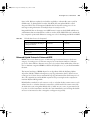
troubleshoot the routing of IP packets in a Cisco router. Tables 13-2 and 13-3 summarize
many of the most common commands used for IP configuration and verification.
You can refer to other sources for more information about basic IP configuration on Cisco
routers. The Cisco IOS documentation is an excellent reference for additional IP commands
(see www.cisco.com/univercd/home/home.htm). Also, the Cisco Press book Interconnecting
Cisco Network Devices is an excellent reference, particularly if you are not able to attend the
instructor-led version of the class. This chapter focuses on the most common commands—
the ones most likely to be on the CCNA exams.
Table 13-2
IP Configuration Commands
Command
Configuration Mode
ip address ip-address mask [secondary]
Interface mode
ip host name [tcp-port-number] address1
[address2...address8]
Global
ip route network-number network-mask {ip-address |
interface} [distance] [name name]
Global
ip name-server server-address1 [[server- address2]…server
address6]
Global
ip domain-lookup
Global
ip routing
Global
hostname name
Global
login
Line configuration mode
password value
Line configuration mode
enable password [level level] {password | [encryption-type]
encrypted-password}
Global
enable secret [level level] {password | [encryption-type]
encrypted-password}
Global
keepalive [seconds]
Interface subcommand
exec-timeout minutes [seconds]
Line subcommand
logging synchronous
Line subcommand
0945_01f.book Page 369 Wednesday, July 2, 2003 3:53 PM
Configuring IP Addresses
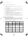
Table 13-3
369
IP EXEC Commands
Command
Function
show hosts
Lists all host names and
corresponding IP
addresses
show interfaces [type number]
Lists interface statistics,
including IP address
show ip interface [type number]
Provides a detailed view
of IP parameter settings
per interface
show ip interface brief
Provides a summary of
all interfaces and their IP
addresses
show ip route [ip-address [mask] [longer-prefixes]] | [protocol
[process-id]]
Shows entire routing
table or a subset if other
parameters are entered
show ip arp [ip-address] [host-name] [mac-address] [type number]
Displays IP ARP cache
debug ip packet
Issues log messages for
each IP packet
terminal ip netmask-format {bitcount | decimal | hexadecimal}
Sets type of display for
subnet masks in show
commands
ping [protocol | tag] {host-name | system-address}
Sends and receives ICMP
echo messages to verify
connectivity
trace [protocol] [destination]
Sends a series of UDP
packets with increasing
TTL values to verify the
current route to a host
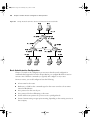
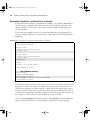
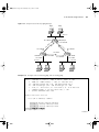
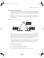
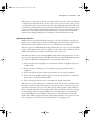
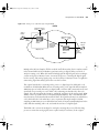
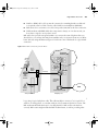
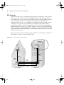
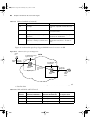
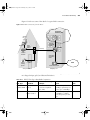
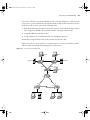
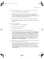
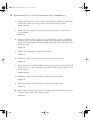
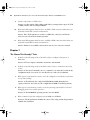
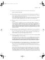
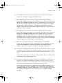
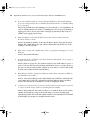
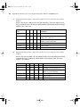
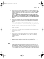
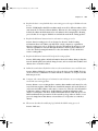
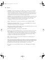
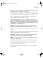
Most of the examples in this chapter refer to the routers in Figure 13-1. The figure shows a
simple network with three routers, with each pair of routers having a serial link to the other
two routers and a local Ethernet.
0945_01f.book Page 370 Wednesday, July 2, 2003 3:53 PM
370
Chapter 13: Basic Router Configuration and Operation
Figure 13-1
Sample Network with Three Routers, with Point-to-Point Serial Links
Bugs
Daffy
10.1.1.0
10.1.1.251
Albuquerque
10.1.128.251
s1
10.1.130.251
1
.1
0
.1
.1
0
1
.1
2
8
.0
s0
3
.0
0
10.1.128.252
s0
10.1.130.253
s0
10.1.129.0
s1
Yosemite
s1
10.1.129.252
10.1.129.253
10.1.2.252
10.1.2.0
Sam
Seville
10.1.3.253
10.1.3.0
Emma
Elmer
Red
Basic Administrative Configuration
Chapter 7 focused on the configuration process more than the actual configuration
commands that happened to be in the chapter. Before you configure IP, this short section
reviews some of the basic commands you typically will configure on any router.
On most routers, you would configure at least the following:
■
A host name for the router
■
Reference to a DNS so that commands typed on the router can refer to host names
instead of IP addresses
■
Set a password on the console port
■
Set a password for those Telnetting to the router
■
Set the enable secret password to protect access to privileged mode
■
Create a banner stating an appropriate warning, depending on the security practices at
that company
0945_01f.book Page 371 Wednesday, July 2, 2003 3:53 PM
Configuring IP Addresses
371
Example 13-1 shows the output of the show running-config command on Albuquerque. The
functions described in the list have been configured using the commands that are highlighted
in the example.
Example 13-1
Basic Adminsitrative Settings on Albuquerque Router
show running-config
Albuquerque#s
Building configuration...
Current configuration : 872 bytes
!
version 12.2
service timestamps debug uptime
service timestamps log uptime
no service password-encryption
!
hostname Albuquerque
!
enable secret 5 $1$J3Fz$QaEYNIiI2aMu.3Ar.q0Xm.
!
!
ip name-server 10.1.1.100
ip name-server 10.1.2.100
!
interface Serial0
!
interface Serial1
!
interface Ethernet0
!
no ip http server
banner motd ^C
Should’ve taken a left turn here! This is Albuquerque...
^C
!
line con 0
password cisco
login
exec timeout 00
line aux 0
line vty 0 4
password cisco
login
loggiing synchronous
None of the commands highlighted in Example 13-1 is required for the router to route IP,
but the commands are generally useful in real networks. Of note, to make the router ask for
a password at the console, you need the login console subcommand; the password console
0945_01f.book Page 372 Wednesday, July 2, 2003 3:53 PM
372
Chapter 13: Basic Router Configuration and Operation
subcommand tells the router what password is required at the console. Similar logic applies
to the login and password vty subcommands. And although you do not have to refer to a
name server, when you do, you typically refer to at least two because most networks have at
least two name servers for redundancy and availability.
When configuring the enable secret command, you type the password just like you want the
user to type it when logging in to the router; however, the IOS changes the value that is saved
in the configuration. For instance, for Example 13-1, I typed enable secret cisco, and the
router changed cisco to a hashed value that cannot be converted back to cisco.
Two other things that you might want to configure habitually on routers are the console
timeout and the synchronization of unsolicited messages. In some cases, you want the router
to exit the user from the console after a period of inactivity. In other cases, you do not want
the console disabled at all because of inactivity. The exec timeout minutes seconds command
sets the inactivity timeout. Also, unsolicited informational messages and output from the IOS
debug command both show up at the console by default. These same messages can be seen
at the aux port or when Telnetting into a router by using the terminal monitor command.
The logging synchronous line subcommand tells the router not to interrupt the output of a
show command with these unsolicited messages, letting you read the output of the command
that you typed before the router displays the other messages. logging synchronous can make
your life a lot easier when using a router.
Configuring IP Addresses
Before you configure IP address, you first must decide what IP addresses to configure. Figure
13-1 not only outlined the network diagram, but it also listed the IP addresses chosen for the
network. In this case, network 10.0.0.0 hs been subnetted with six subnets and a mask of
255.255.255.0.
After you have chosen the IP addresses and masks, configuration is simple. Examples 13-2,
13-3, and 13-4 show the IP configuration details for the three routers in Figure 13-1. The full
configuration for Albuquerque is shown in Example 13-2, with a briefer version of the
configs of the other two routers in Examples 13-3 and 13-4.
Example 13-2
Albuquerque Router Configuration and Exec Commands
configure terminal
Albuquerque#c
Enter configuration commands, one per line.
End with CNTL/Z.
interface serial 0
Albuquerque(config)#i
ip address 10.1.128.251 255.255.255.0
Albuquerque(config-if)#i
interface serial 1
Albuquerque(config)#i
ip address 10.1.130.251 255.255.255.0
Albuquerque(config-if)#i
interface ethernet 0
Albuquerque(config)#i
ip address 10.1.1.251 255.255.255.0
Albuquerque(config-if)#i
0945_01f.book Page 373 Wednesday, July 2, 2003 3:53 PM
Configuring IP Addresses
Example 13-2
373
Albuquerque Router Configuration and Exec Commands (Continued)
show running-config
Albuquerque#s
Building configuration...
Current configuration : 872 bytes
!
version 12.2
service timestamps debug uptime
service timestamps log uptime
no service password-encryption
!
hostname Albuquerque
!
enable secret 5 $1$J3Fz$QaEYNIiI2aMu.3Ar.q0Xm.
!
!
ip name-server 10.1.1.100
ip name-server 10.1.2.100
!
interface Serial0
ip address 10.1.128.251 255.255.255.0
!
interface Serial1
ip address 10.1.130.251 255.255.255.0
!
interface Ethernet0
ip address 10.1.1.251 255.255.255.0
!
no ip http server
banner motd ^C
Should’ve taken a left turn here! This is Albuquerque...
^C
!
line con 0
password cisco
login
line aux 0
line vty 0 4
password cisco
login
!
end
show ip route
Albuquerque#s
Codes: C - connected, S - static, I - IGRP, R - RIP, M - mobile, B - BGP
D - EIGRP, EX - EIGRP external, O - OSPF, IA - OSPF inter area
N1 - OSPF NSSA external type 1, N2 - OSPF NSSA external type 2
continues
0945_01f.book Page 374 Wednesday, July 2, 2003 3:53 PM
374
Chapter 13: Basic Router Configuration and Operation
Example 13-2
Albuquerque Router Configuration and Exec Commands (Continued)
E1 - OSPF external type 1, E2 - OSPF external type 2, E - EGP
i - IS-IS, L1 - IS-IS level-1, L2 - IS-IS level-2, ia - IS-IS inter area
* - candidate default, U - per-user static route, o - ODR
P - periodic downloaded static route
Gateway of last resort is not set
10.0.0.0/24 is subnetted, 3 subnets
C
10.1.1.0 is directly connected, Ethernet0
C
10.1.130.0 is directly connected, Serial1
C
10.1.128.0 is directly connected, Serial0
terminal ip netmask-format decimal
Albuquerque#t
show ip route
Albuquerque#s
Codes: C - connected, S - static, I - IGRP, R - RIP, M - mobile, B - BGP
D - EIGRP, EX - EIGRP external, O - OSPF, IA - OSPF inter area
N1 - OSPF NSSA external type 1, N2 - OSPF NSSA external type 2
E1 - OSPF external type 1, E2 - OSPF external type 2, E - EGP
i - IS-IS, L1 - IS-IS level-1, L2 - IS-IS level-2, ia - IS-IS inter area
* - candidate default, U - per-user static route, o - ODR
P - periodic downloaded static route
Gateway of last resort is not set
10.0.0.0 255.255.255.0 is subnetted, 3 subnets
C
10.1.1.0 is directly connected, Ethernet0
C
10.1.130.0 is directly connected, Serial1
C
10.1.128.0 is directly connected, Serial0
Example 13-3
Yosemite Router Configuration and Exec Commands
show running-config
Yosemite#s
Building configuration...
! Lines ommitted for brevity
!
interface Serial0
ip address 10.1.128.252 255.255.255.0
!
interface Serial1
ip address 10.1.129.252 255.255.255.0
!
interface Ethernet0
ip address 10.1.2.252 255.255.255.0
!
! lines ommitted for brevity
0945_01f.book Page 375 Wednesday, July 2, 2003 3:53 PM
Configuring IP Addresses
Example 13-4
375
Seville Router Configuration and Exec Commands
show running-config
Seville#s
! Lines ommitted for brevity
!
!
interface Serial0
ip address 10.1.130.253 255.255.255.0
!
interface Serial1
ip address 10.1.129.253 255.255.255.0
!
Ethernet0
ip address 10.1.3.253 255.255.255.0
!
! Lines ommitted for brevity
The ip address interface subcommand configures the IP address for each interface, as seen in
the highlighted portions of the examples. Because each interface has an IP address, the
interface configuration command precedes each ip address command, identifying to IOS the
interface to which the IP address should be assigned. It’s that simple!
Prefix Notation
At the end of Example 13-2 (Albuquerque), you also see the results of the show ip route
command. The output of the command lists the network (10.0.0.0), followed by the notation
of /24. This notation, called prefix notation, denotes the subnet mask in terms of the number
of 1 bits in the subnet mask. The number of bits of value binary 1 in the mask is considered
to be the prefix. For instance, mask 255.255.255.0, used in the examples, translates to a
prefix of /24 because 255.255.255.0 has 24 binary 1s. Prefix notation is simply a shorter way
to write the mask.
If you prefer to see the subnet masks instead of the prefix, simply use the terminal ip netmaskformat decimal exec command, as shown at the end of Example 13-2. Note that the show ip
route command issued after the terminal command shows the subnet mask instead of the
prefix.
Seeding the Routing Table with Connected IP Routes
The Cisco IOS routes IP packets by default—in other words, you do not need to type any
commands to tell the router to enable IP routing. Before the router will route packets in or
out an interface, the interface must have an IP address, as shown in the earlier examples. So,
as configured, each of the three routers can route packets on three different interfaces.
0945_01f.book Page 376 Wednesday, July 2, 2003 3:53 PM
376
Chapter 13: Basic Router Configuration and Operation
The problem with the configurations shown so far is that the routers do not know routes to
all the subnets in the network. The ultimate solution to this problem is to configure a
dynamic routing protocol. However, in this chapter, you will learn about how the router
learns some routes by virtue of the configuration of IP addresses on the interface. Chapter 14
introduces the different IP routing protocols, and the CCNA ICND Exam Certification
Guide covers the detailed concepts and configuration for several IP routing protocols.
Routers add routes to their routing tables for the subnets associated with their own physical
interfaces. To get a better appreciation of this fact, examine Example 13-5, which shows
several commands from the Seville router.
Example 13-5
Seville Router Routing Table and Interface Status Commands
show ip route
Seville#s
Codes: C - connected, S - static, I - IGRP, R - RIP, M - mobile, B - BGP
D - EIGRP, EX - EIGRP external, O - OSPF, IA - OSPF inter area
N1 - OSPF NSSA external type 1, N2 - OSPF NSSA external type 2
E1 - OSPF external type 1, E2 - OSPF external type 2, E - EGP
i - IS-IS, L1 - IS-IS level-1, L2 - IS-IS level-2, ia - IS-IS inter area
* - candidate default, U - per-user static route, o - ODR
P - periodic downloaded static route
Gateway of last resort is not set
10.0.0.0/24 is subnetted, 3 subnets
C
10.1.3.0 is directly connected, Ethernet0
C
10.1.130.0 is directly connected, Serial0
C
10.1.129.0 is directly connected, Serial1
show ip interface brief
Seville#s
Interface
IP-Address
OK? Method Status
Protocol
Serial0
10.1.130.253
YES manual up
up
Serial1
10.1.129.253
YES manual up
up
Ethernet0
10.1.3.253
YES manual up
up
Yosemite#
show interface serial 0
Seville#s
Serial0 is up, line protocol is up
Hardware is HD64570
Internet address is 10.1.130.253/24
MTU 1500 bytes, BW 1544 Kbit, DLY 20000 usec,
reliability 255/255, txload 1/255, rxload 1/255
Encapsulation HDLC, loopback not set
Keepalive set (10 sec)
Last input never, output never, output hang never
Last clearing of “show interface” counters never
Input queue: 0/75/0/0 (size/max/drops/flushes); Total output drops: 0
Queueing strategy: weighted fair
Output queue: 0/1000/64/0 (size/max total/threshold/drops)
Conversations
0/0/256 (active/max active/max total)
0945_01f.book Page 377 Wednesday, July 2, 2003 3:53 PM
Configuring IP Addresses
Example 13-5
Seville Router Routing Table and Interface Status Commands (Continued)
Reserved Conversations 0/0 (allocated/max allocated)
Available Bandwidth 1158 kilobits/sec
5 minute input rate 0 bits/sec, 0 packets/sec
5 minute output rate 0 bits/sec, 0 packets/sec
0 packets input, 0 bytes, 0 no buffer
Received 0 broadcasts, 0 runts, 0 giants, 0 throttles
0 input errors, 0 CRC, 0 frame, 0 overrun, 0 ignored, 0 abort
0 packets output, 0 bytes, 0 underruns
0 output errors, 0 collisions, 1 interface resets
0 output buffer failures, 0 output buffers swapped out
0 carrier transitions
DCD=up
DSR=up
DTR=up
RTS=up
CTS=up
show ip interface serial 1
Seville#s
Serial1 is up, line protocol is up
Internet address is 10.1.129.253/24
Broadcast address is 255.255.255.255
Address determined by non-volatile memory
MTU is 1500 bytes
Helper address is not set
Directed broadcast forwarding is disabled
Outgoing access list is not set
Inbound
access list is not set
Proxy ARP is enabled
Security level is default
Split horizon is disabled
ICMP redirects are always sent
ICMP unreachables are always sent
ICMP mask replies are never sent
IP fast switching is enabled
IP fast switching on the same interface is enabled
IP Flow switching is disabled
IP Feature Fast switching turbo vector
IP multicast fast switching is disabled
IP multicast distributed fast switching is disabled
IP route-cache flags are Fast
Router Discovery is disabled
IP output packet accounting is disabled
IP access violation accounting is disabled
TCP/IP header compression is disabled
RTP/IP header compression is disabled
Probe proxy name replies are disabled
Policy routing is disabled
Network address translation is disabled
WCCP Redirect outbound is disabled
WCCP Redirect inbound is disabled
WCCP Redirect exclude is disabled
BGP Policy Mapping is disabled
377
0945_01f.book Page 378 Wednesday, July 2, 2003 3:53 PM
378
Chapter 13: Basic Router Configuration and Operation
First, here is a quick introduction to the four commands in the example. The show ip route
command lists routes to the three subnets connected to the Seville router, namely 10.1.130.0,
10.1.129.0, and 10.1.3.0, all with mask 255.255.255.0 (prefix /24). The output from the
command lists a C in the first column, which, according to the notes at the beginning of the
command output, means “connected.” In other words, this router is connected directly to
these subnets.
Following the show ip route command, the example contains three commands that list
information about the interfaces in the router. The show ip interfaces brief command lists
one line per interface, with IP address information and interface status. Next, the show
interfaces serial 0 command lists more details about a single interface, with most of those
details about the interface itself. Finally, the show ip interfaces serial 1 command shows
detailed information about the IP protocol running over interface serial 1.
IOS adds connected routes to the routing table that meet the following requirements:
■
The interface has been configured with a valid IP address.
■
The interface is in an up and up status according to the various interface-oriented show
commands.
All three of the show commands in Example 13-5 that list interface status information use
two designations of up and up. The first status keyword (the first of the two ups in this case)
generally refers to OSI Layer 1 status. For instance, if there is no cable plugged in, the first
status word would be down instead of up. The second status word generally refers to the
status of OSI Layer 2. For instance, if Seville defaulted to use HDLC on serial 0, but
Albuquerque configured PPP as the data-link protocol on its serial 1 interface on the other
end of the link, the interface status on each end would show up and down.
Another instance in which a router might put an interface in status up and down is when the
router does not receive keepalive messages on a regular basis. Cisco routers send, and expect
to receive, proprietary keepalive messages on each interface. The purpose of the keepalives
is to know whether the interface is usable. For instance, on a point-to-point link between
Albuquerque and Yosemite, each router sends a keepalive every 10 seconds. As long as they
each receive a keepalive every 10 seconds, they think the link is up and up. If Yosemite did
not hear a keepalive for three times the keepalive interval (default 10-second interval, for a
total of 30 seconds), Yosemite would put the interface into an up and down status. You can
disable keepalives with the no keepalive interface subcommand, or you can change the timer
with the keepalive interval interface subcommand.
Those comments aside, as long as an interface status is up and up, the router believes that the
interface is usable, so the router can add the associated connected IP route to the routing table.
0945_01f.book Page 379 Wednesday, July 2, 2003 3:53 PM
Configuring IP Addresses
379
In some cases, you want an interface to be down for administrative reasons, but you do not
want to have to unconfigure it or pull out the cable to keep the interface from being up and
up. To bring down an interface for administrative reasons and, as a side effect, remove the
connected route from the routing table, you can use the shutdown interface subcommand, as
shown in Example 13-6.
Example 13-6
Using the shutdown Command
configure terminal
Seville#c
Enter configuration commands, one per line.
End with CNTL/Z.
interface serial 1
Seville(config)#i
shutdown
Seville(config-if)#s
^Z
Seville(config-if)#^
show ip route
Seville#s
Codes: C - connected, S - static, I - IGRP, R - RIP, M - mobile, B - BGP
D - EIGRP, EX - EIGRP external, O - OSPF, IA - OSPF inter area
N1 - OSPF NSSA external type 1, N2 - OSPF NSSA external type 2
E1 - OSPF external type 1, E2 - OSPF external type 2, E - EGP
i - IS-IS, L1 - IS-IS level-1, L2 - IS-IS level-2, ia - IS-IS inter area
* - candidate default, U - per-user static route, o - ODR
P - periodic downloaded static route
Gateway of last resort is not set
10.0.0.0/24 is subnetted, 2 subnets
C
10.1.3.0 is directly connected, Ethernet0
C
10.1.130.0 is directly connected, Serial0
show ip interface brief
Seville#s
Interface
IP-Address
OK? Method Status
Protocol
Serial0
10.1.130.253
YES manual up
up
Serial1
10.1.129.253
YES manual Administratively down down
Ethernet0
10.1.3.253
YES manual up
up
configure terminal
Seville#c
Enter configuration commands, one per line.
End with CNTL/Z.
interface serial 1
Seville(config)#i
no shutdown
Seville(config-if)#n
^Z
Seville(config-if)#^
In the example, after the shutdown command under interface serial 1, the route connected
to serial 1 (10.1.129.0, mask 255.255.255.0) was removed from the routing table, leaving
only two entries. Also, the output of the show ip interfaces brief command lists a status of
administratively down and down. (The show ip interfaces and show interfaces commands
would show the same status for serial 1.) At the end of the example, the no shutdown
command brings the interface back up.
0945_01f.book Page 380 Wednesday, July 2, 2003 3:53 PM
380
Chapter 13: Basic Router Configuration and Operation
Bandwidth, Clock Rate, and Serial Lines in the Lab
As mentioned back in Chapter 4, “Fundamentals of WANs,” you can build a WAN link in a
lab without using a CSU/DSU. The lab network that I used to build the examples in this
chapter used three “back-to-back” serial cables, essentially a DTE and DCE cable pair
connected together.
To use a back-to-back WAN connection, one router must supply the clocking. Example 13-7
shows an example configuration for Seville, with a couple of important commands related to
WAN links.
Example 13-7
Seville Router Configuration with clock rate Command
show running-config
Seville#s
! Lines ommitted for brevity
!
interface Serial0
ip address 10.1.130.253 255.255.255.0
clock rate 128000
!
interface Serial1
ip address 10.1.129.253 255.255.255.0
clock rate 128000
bandwidth 128
!
Ethernet0
ip address 10.1.3.253 255.255.255.0
!
! Lines ommitted for brevity
show controllers serial 0/0
Seville#s
Interface Serial0
Hardware is PowerQUICC MPC860
DCE V.35, clock rate 128000
idb at 0x8169BB20, driver data structure at 0x816A35E4
! Lines ommitted for brevity
The clock rate command sets the rate in bits per second on the router that has the DCE cable
plugged into it. In this case, Seville was supplying clocking on both serial interfaces. If no
cable has been plugged in, the IOS accepts the command. If a DTE cable has been plugged
in, IOS rejects the command. If you do not know which router has the DCE cable in it, you
can find out by using the show controllers command, as shown at the end of the example. In
the example, you can see that the output identifies the type of serial cable.
Also notice the bandwidth 128 command on serial 1. The bandwidth command tells IOS the
speed of the link, in kilobits per second, regardless of whether the router is supplying
0945_01f.book Page 381 Wednesday, July 2, 2003 3:53 PM
IP Troubleshooting Features
381
clocking. The bandwidth setting does not change anything that the router does at Layer 1;
instead, this setting is used by IOS software for other purposes. For instance, IGRP and
EIGRP both use bandwidth to calculate a metric for routing protocols; they use the
bandwidth setting on the interfaces. bandwidth defaults to T1 speed on serial interfaces.
There is no default for clock rate, even with a DCE cable plugged in—it must be configured.
IP Troubleshooting Features
Cisco includes coverage of basic troubleshooting commands and concepts on the CCNA
exams. These commands are contained in several places in this book, as well as in the CCNA
ICND Exam Certification Guide. This section covers some of the tools and commands
specific to troubleshooting IP.
Internet Control Message Protocol
Earlier in this chapter, you read about how to configure IP addresses and how to perform
some basic troubleshooting. For troubleshooting, you have seen how to look at the routing
table with the show ip route command, how to look at interface status with several options
on the show interfaces command, and how to use standard and extended ping commands for
basic troubleshooting.
TCP/IP includes a protocol specifically to help manage and control the operation of a
TCP/IP network, called the Internet Control Message Protocol (ICMP). The ICMP protocol
provides a wide variety of information about the health and operational status of a network.
Control Message is the most descriptive part of the name—ICMP defines messages that helps
control and manage the work of IP and, therefore, is considered to be part of TCP/IP’s
network layer. Because ICMP helps control IP, it can provide useful troubleshooting
information. In fact, the ICMP messages sit inside an IP packet, with no transport layer
header at all–so it is truly just an extension of the TCP/IP network layer.
RFC 792 defines ICMP and includes the following excerpt, which describes the protocol well:
Occasionally a gateway (router) or destination host will communicate with a source
host, for example, to report an error in datagram processing. For such purposes,
this protocol, the Internet Control Message Protocol (ICMP), is used. ICMP uses
the basic support of IP as if it were a higher level protocol; however, ICMP is
actually an integral part of IP and must be implemented by every IP module.
ICMP uses messages to accomplish its tasks. Many of these messages are used in even the
smallest IP network. Table 13-4 lists several ICMP messages.
0945_01f.book Page 382 Wednesday, July 2, 2003 3:53 PM
382
Chapter 13: Basic Router Configuration and Operation
Table 13-4
ICMP Message Types
Message
Purpose
Destination unreachable
This tells the source host that there is a problem delivering a
packet.
Time exceeded
The time that it takes a packet to be delivered has expired; the
packet has been discarded.
Redirect
The router sending this message has received some packet for
which another router would have had a better route; the message
tells the sender to use the better route.
Echo
This is used by the ping command to verify connectivity.
ICMP Echo Request and Echo Reply
The ICMP echo request and echo reply messages are sent and received by the ping command.
In fact, when people say that they “sent a ping packet,” they really mean that they sent an
ICMP echo request. These two messages are very self-explanatory. The echo request simply
means that the host to which it is addressed should reply to the packet. The echo reply is the
ICMP message type that should be used in the reply. The echo request includes some data
that can be specified by the ping command; whatever data is sent in the echo request is sent
back in the echo reply.
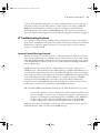
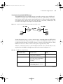
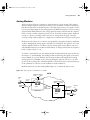
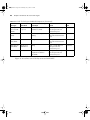
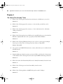
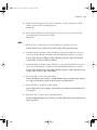
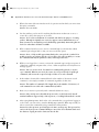
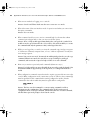
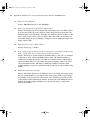
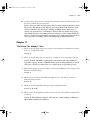
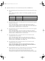
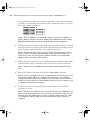
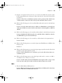
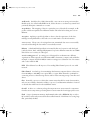
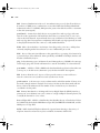
Example 13-8 shows two ping commands testing IP connectivity from Albuquerque to
Yosemite. Figure 13-2 precedes the example, as a reminder of the topology and IP addresses
in the network.
0945_01f.book Page 383 Wednesday, July 2, 2003 3:53 PM
IP Troubleshooting Features
Figure 13-2
383
Sample Network Used for ping Example
Bugs
Daffy
10.1.1.0
10.1.1.251
Albuquerque
10.1.128.251
s1 10.1.130.251
10
.0
30
.1
10.1.128.252
s0
.1
.1
10
.1
28
.0
s0
10.1.130.253
s0
10.1.129.0
s1
10.1.129.252
Yosemite
10.1.2.252
s1
10.1.129.253
Seville
10.1.3.253
10.1.2.0
Sam
Example 13-8
10.1.3.0
Emma
Elmer
Red
Example with One Working ping, and One Failing ping
show ip route
Albuquerque#s
Codes: C - connected, S - static, I - IGRP, R - RIP, M - mobile, B - BGP
D - EIGRP, EX - EIGRP external, O - OSPF, IA - OSPF inter area
N1 - OSPF NSSA external type 1, N2 - OSPF NSSA external type 2
E1 - OSPF external type 1, E2 - OSPF external type 2, E - EGP
i - IS-IS, L1 - IS-IS level-1, L2 - IS-IS level-2, ia - IS-IS inter area
* - candidate default, U - per-user static route, o - ODR
P - periodic downloaded static route
Gateway of last resort is not set
10.0.0.0/24 is subnetted, 3 subnets
C
10.1.1.0 is directly connected, Ethernet0
C
10.1.130.0 is directly connected, Serial1
C
10.1.128.0 is directly connected, Serial0
ping 10.1.128.252
Albuquerque#p
Type escape sequence to abort.
continues
0945_01f.book Page 384 Wednesday, July 2, 2003 3:53 PM
384
Chapter 13: Basic Router Configuration and Operation
Example 13-8
Example with One Working ping, and One Failing ping
Sending 5, 100-byte ICMP Echos to 10.1.128.252, timeout is 2 seconds:
!!!!!
Success rate is 100 percent (5/5), round-trip min/avg/max = 4/4/8 ms
ping 10.1.2.252
Albuquerque#p
Type escape sequence to abort.
Sending 5, 100-byte ICMP Echos to 10.1.2.252, timeout is 2 seconds:
.....
Success rate is 0 percent (0/5)
The ping command sends a packet to the stated destination address. The TCP/IP software at
the destination then replies to the ping packet with a similar packet. The ping command
sends the first packet and waits on the response. If a response is received, the command
displays an exclamation mark (!). If no response is received within the default timeout of 2
seconds, the ping command displays a period (.). The IOS ping command sends five of these
packets by default.
In Example 13-8, the ping 10.1.128.2 command works, but the ping 10.1.2.252 command
does not. The first ping command works because Albuquerque has a route to the subnet in
which 10.1.128.2 resides (subnet 10.1.128.0). However, the second ping to 10.1.2.252 does
not work because the subnet in which 10.1.2.252 resides, subnet 10.1.2.0, is not connected
to Albuquerque, so Albuquerque does not have a route to that subnet. So, none of the five
ping packets works, resulting in five periods in the output of the ping command. (The ping
would have worked if a routing protocol had been implemented successfully in this
network.) Had these routers been using a routing protocol, the correct routes would have
been known, and the second ping would have worked.
The ping command itself supplies many creative ways to use echo requests and replies. For
instance, the ping command enables you to specify the length as well as the source and
destination addresses, and it also enables you to set other fields in the IP header.
0945_01f.book Page 385 Wednesday, July 2, 2003 3:53 PM
IP Troubleshooting Features
385
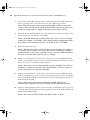
Destination Unreachable ICMP Message
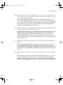
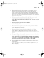
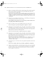
The ICMP Destination Unreachable message is sent when a message cannot be delivered
completely to the application at the destination host. Because packet delivery can fail for
many reasons, there are five separate unreachable functions (codes) using this single ICMP
unreachable message. All five code types pertain directly to an IP, TCP, or UDP feature. The
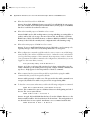
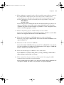
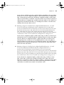
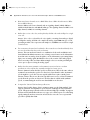
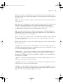
network shown in Figure 13-3 helps you understand them.
Figure 13-3
Sample Network for Discussing ICMP Unreachable Codes
10.1.1.0 / 24
10.1.2.0 / 24
A
B
10.1.3.0 / 24
Web
Fred
10.1.2.14
Assume that Fred is trying to connect to the web server, called Web. (Web uses HTTP, which
in turn uses TCP as the transport layer protocol.) Three of the ICMP unreachable codes can
possibly be used by Routers A and B. The other two codes are used by the web server. These
ICMP codes are sent to Fred as a result of the packet originally sent by Fred.
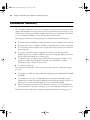
Table 13-5 summarizes the more common ICMP unreachable codes. After the table, the text
explains how each ICMP code might be needed for the network in Figure 13-3.
Table 13-5
ICMP Unreachable Codes
What It Typically Is
Sent By
Unreachable Code
When It Is Used
Network unreachable
There is no match in a routing table
for the packet’s destination.
Router
Host unreachable
The packet can be routed to a
router connected to the destination
subnet, but the host is not
responding.
Router
Can’t fragment
The packet has the Don’t Fragment
bit set, and a router must fragment
to forward the packet.
Router
continues
0945_01f.book Page 386 Wednesday, July 2, 2003 3:53 PM
386
Chapter 13: Basic Router Configuration and Operation
Table 13-5
ICMP Unreachable Codes (Continued)
What It Typically Is
Sent By
Unreachable Code
When It Is Used
Protocol unreachable
The packet is delivered to the
destination host, but the transport
layer protocol is not available on
that host.
Endpoint host
Port unreachable
The packet is delivered to the
destination host, but the
destination port has not been
opened by an application.
Endpoint host
The following list explains each code in Table 8-8 in greater detail using the network in
Figure 13-3 as an example:
■
Network unreachable—Router A uses this code if it does not have a route telling it where
to forward the packet. In this case, Router A needs a route to subnet 10.1.2.0. Router A
sends Fred the ICMP Destination Unreachable message with the code “network
unreachable” in response to Fred’s packet destined for 10.1.2.14.
■
Host unreachable—This code implies that the single destination host is unavailable. If
Router A has a route to 10.1.2.0, the packet is delivered to Router B. However, if the
web server is down, Router B does not get an ARP reply from the web server. Router B
sends Fred the ICMP Destination Unreachable message with the code “host
unreachable” in response to Fred’s packet destined for 10.1.2.14.
■
Can’t fragment—This code is the last of the three ICMP unreachable codes that a router
might send. Fragmentation defines the process in which a router needs to forward a
packet, but the outgoing interface allows only packets that are smaller than the
forwarded packet. The router can break the packet into pieces. However, if Router A or
B needs to fragment the packet but the Do Not Fragment bit is set in the IP header, the
router discards the packet. Router A or B sends Fred the ICMP Destination Unreachable
message with the code “can’t fragment” in response to Fred’s packet destined for
10.1.2.14.
■
Protocol unreachable—If the packet successfully arrives at the web server, two other
unreachable codes are possible. One implies that the protocol above IP, typically TCP or
UDP, is not running on that host. This is highly unlikely, because most operating systems
that use TCP/IP use a single software package that provides IP, TCP, and UDP functions.
But if the host receives the IP packet and TCP or UDP is unavailable, the web server host
sends Fred the ICMP Destination Unreachable message with the code “protocol
unreachable” in response to Fred’s packet destined for 10.1.2.14.
0945_01f.book Page 387 Wednesday, July 2, 2003 3:53 PM
IP Troubleshooting Features
387
Port unreachable—The final code field value is more likely today. If the server is up but
the web server software is not running, the packet can get to the server but cannot be
delivered to the web server software. The web server host sends Fred the ICMP
Destination Unreachable message with the code “port unreachable” in response to Fred’s
packet destined for 10.1.2.14.
■
One key to troubleshooting with the ping command is understanding the various codes the
command uses to signify the various responses it can receive. Table 13-6 lists the various
codes that the Cisco IOS software ping command can supply.
Codes That the ping Command Receives in Response to Its ICMP Echo Request
Table 13-6
ping Command Code
Description
!
ICMP Echo Reply received
.
Nothing was received before the ping command timed out
U
ICMP unreachable (destination) received
N
ICMP unreachable (network) received
P
ICMP unreachable (port) received
Q
ICMP source quench received
M
ICMP Can’t Fragment message received
?
Unknown packet received
IP Naming Commands
When using the IOS CLI, you will want to refer to names instead of IP addresses. Particularly
for the trace, ping, and telnet commands, the IP address or host name must be supplied. This
section describes the use of host names on an IOS-based device. Along the way, some nuances
of the use of Telnet are covered.
IOS can use statically configured names as well as refer to one or more DNSs. Example 13-9
shows some names statically configured, with configuration pointing to two different DNSs.
Example 13-9
IP Naming Configuration and show host Command
hostname Cooperstown
!
ip host Mays 10.1.1.1
ip host Aaron 10.2.2.2
ip host Mantle 10.3.3.3
!
ip domain-name gileadfoundation.org
ip name-server 10.1.1.200
10.2.2.200
ip domain-lookup
continues
0945_01f.book Page 388 Wednesday, July 2, 2003 3:53 PM
388
Chapter 13: Basic Router Configuration and Operation
IP Naming Configuration and show host Command (Continued)
Example 13-9
show hosts
Cooperstown#s
Default domain is gileadoundation.org
Name/address lookup uses static mappings
Host
Flags
Mays
(perm, OK)
Age Type
0
IP
Address(es)
10.1.1.1
Aaron
(perm, OK)
0
IP
10.2.2.2
Mantle
(perm, OK)
0
IP
10.3.3.3
Cooperstown
Router Cooperstown will use any of the three statically configured host name–to–IP address
mappings. Three names are configured statically in this case—Mays, Aaron, and Mantle.
Any command referring to Mays, Aaron, or Mantle will resolve into the IP addresses shown
in the ip host command.
Router Cooperstown also will ask a DNS for name resolution if it does not know the name
and IP address already. The DNS configuration is shown toward the end of the configuration.
The IP addresses of the name servers are shown in the ip name-server command. Up to six
DNSs can be listed; they are searched for each request sequentially, based on the order in the
command. Finally, the ip domain-lookup command enables IOS to ask a name server. IP
domain lookup is the default; no ip domain-lookup disables the DNS client function. For
names that do not include the full domain name, the ip domain-name command defines the
domain name that should be assumed by the router.
The show ip host command lists the static entries, in addition to any entries learned from a DNS
request. Only the three static entries were in the table, in this case. The term perm in the output
implies that the entry is static. Also note that when short names are used—in other words, the
name does not include the DNS domain name—the router adds the domain name of
gileadfoundation.org, as configured in the ip domain-name gileadfoundation.org command.
Table 13-7 summarizes the key naming commands in IOS.
Table 13-7
IP Naming Commands
Function
Command Options
Tell IOS to use a DNS
Configure the ip domain-lookup global configuration command.
Configure IP
addresses of name
servers
Configure the ip name-server svr1 svr2... global configuration
command.
Configure static host
names
Use the ip host name address command.
List current host name
information
Use the show hosts exec command.
0945_01f.book Page 389 Wednesday, July 2, 2003 3:53 PM
IP Troubleshooting Features
389
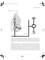
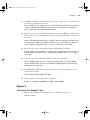
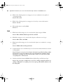
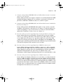
Telnet and Suspend
The telnet IOS exec command enables you to Telnet from one Cisco device to another; in
practical use, it is typically to another Cisco device. One of the most important features of
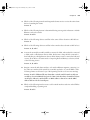
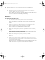
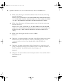
the telnet command is the suspend feature. To understand the suspend function, you should
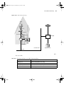
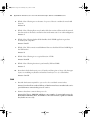
to refer to the network diagram in Figure 13-4.
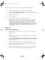
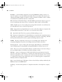
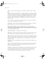
Figure 13-4
Telnet Suspension
Bench
Cincy
Frame
Relay
Milwaukee
New York
Uecker
Berra
In the figure, the router administrator is using Bench to Telnet into the Cincy router. When
in Cincy, the user Telnets to Milwaukee. When in Milwaukee, the user suspends the Telnet
by pressing Ctrl-Shift-6, followed by pressing the letter x. The user then Telnets to New York
and again suspends the connection. The example begins with Bench already logged into
Cincy. Example 13-10 shows example output, with annotations to the side.
Example 13-10
Telnet Suspensions
telnet milwaukee
Cincy#t
(User issues command to Telnet to Milwaukee)
Trying Milwaukee (10.1.4.252)... Open
User Access Verification
Password:
(User plugs in password, can type commands at Milwaukee)
continues
0945_01f.book Page 390 Wednesday, July 2, 2003 3:53 PM
390
Chapter 13: Basic Router Configuration and Operation
Example 13-10
Telnet Suspensions (Continued)
Milwaukee>
Milwaukee>
Milwaukee>
(Note: User pressed Ctrl-Shift-6 and then x)
telnet NewYork
Cincy#t
(User back at Cincy because Telnet was suspended)
Trying NewYork (10.1.6.253)... Open
(User is getting into New York now, based on telnet NewYork command)
User Access Verification
Password:
NewYork>
(User can now type commands on New York)
NewYork>
NewYork>
NewYork>
(Note: User pressed Ctrl-Shift-6 and then x)
show sessions
Cincy#s
Conn Host
*
(This command lists suspended Telnet sessions)
Address
Byte
Idle Conn Name
1 milwaukee
10.1.4.252
0
0 milwaukee
2 NewYork
10.1.6.253
0
0 NewYork
where
Cincy#w
(where does the same thing)
Conn Host
*
Address
Byte
Idle Conn Name
1 milwaukee
10.1.4.252
0
0 milwaukee
2 NewYork
10.1.6.253
0
0 NewYork
resume 1
Cincy#r
(Resume connection 1 (see show session) to Milwaukee)
[Resuming connection 1 to milwaukee ... ]
Milwaukee>
(User can type commands on Milwaukee)
Milwaukee>
Milwaukee>
(Note: User pressed Ctrl-Shift-6 and then x)
Cincy#
(User wants to go back to Cincy)
(WOW! User just pressed Enter and resumes the last Telnet)
[Resuming connection 1 to milwaukee ... ]
Milwaukee>
Milwaukee>
Milwaukee>
(Note: User pressed Ctrl-Shift-6 and then x)
(Tired of Milwaukee again
disconnect 1
Cincy#d
can’t imagine why!)
(No more need to use Milwaukee
Closing connection to milwaukee [confirm]
Cincy#
[Resuming connection 2 to NewYork ... ]
Telnet terminated!)
(User presses Enter to confirm)
0945_01f.book Page 391 Wednesday, July 2, 2003 3:53 PM
IP Troubleshooting Features
Example 13-10
391
Telnet Suspensions (Continued)
(Pressing Enter resumes most recently suspended active Telnet)
NewYork>
NewYork>
NewYork>
(Note: User pressed Ctrl-Shift-6 and then x)
disconnect 2
Cincy#d
Closing connection to NewYork [confirm]
(Done with New York, terminate Telnet)
(Just press Enter to confirm)
Cincy#
The play-by-play notes in the example explain most of the details. Example 13-10 begins
with the Cincy command prompt that would be seen in Bench’s Telnet window because the
user at Bench Telnetted into Cincy first. After Telnetting to Milwaukee, the Telnet connection
was suspended. Then, after Telnetting to New York, that connection was suspended. The two
connections can be suspended or resumed easily. The resume command can be used to
resume either connection; however, the resume command requires a connection ID, which is
shown in the show sessions command. (The where command provides the same output.)
Also, instead of using the resume command, you can just use the session number as a
command. For instance, just typing the command 2 does the same thing as typing the
command resume 2.
The interesting and potentially dangerous nuance here is that if a Telnet session is suspended
and you simply press Enter, Cisco IOS Software resumes the connection to the most recently
suspended Telnet connection. That is fine, until you realize how much you tend to press the
Enter key occasionally to clear some of the clutter from the screen. With a suspended Telnet
connection, you also just happened to reconnect to another router. This is particularly
dangerous when you are changing the configuration or using potentially damaging exec
commands—be careful about what router you are actually using when you have suspended
Telnet connections.
If you want to know which session has been suspended most recently, look for the session
listed in the show session command that has an asterisk to the left of the entry. That session
was the most recently suspended session.
0945_01f.book Page 392 Wednesday, July 2, 2003 3:53 PM
392
Chapter 13: Basic Router Configuration and Operation
Table 13-8 summarizes the commands related to Telnet.
Table 13-8
Telnet Command Options
Function
Command Options
Telnet to another device
Use the telnet exec command.
Just type the host name or IP address from exec mode.
Suspend a Telnet session
Press the key sequence Ctrl-Shift-6, then x.
Discover currently
suspended Telnet session
Use the where exec command.
Use the show sessions exec command.
Resume a suspended
Telnet session
Use the resume command, with no parameter, to reconnect to the
most recently suspended Telnet.
Use the resume x command, where x is the number of the
suspended Telnet session based on the output of show sessions.
Just press Enter in exec mode to resume to the most recently
suspended Telnet session.
Terminate a suspended
telnet
Resume connection, and log out using the quit command.
Use the disconnect command on the router you Telnnetted from.
Cisco Discovery Protocol
The Cisco Discovery Protocol (CDP) discovers basic information about neighboring routers
and switches, without needing to know the passwords for the neighboring devices. CDP
supports any LAN, HDLC, Frame Relay, and ATM interface—in fact, it supports any
interface that supports the use of SNAP headers. The router or switch can discover Layer 2
and Layer 3 addressing details of neighboring routers without even configuring that Layer 3
protocol—this is because CDP is not dependent on any particular Layer 3 protocol.
When Cisco first developed the proprietary CDP, it was used mainly between routers. Today
most Cisco products support CDP, including Cisco switches and Cisco IP Phones.
Devices that support CDP advertise their own information and learn information about
others by listening for their advertisements. On media that support multicasts at the data link
layer, CDP uses multicast; on other media, CDP sends a copy of the CDP update to any
known data-link addresses. So, any CDP-supporting device that shares a physical medium
with another CDP-supporting device can learn about the other device.
0945_01f.book Page 393 Wednesday, July 2, 2003 3:53 PM
IP Troubleshooting Features
393
CDP discovers several useful details from the neighboring device:
■
Device identifier—Typically the host name
■
Address list—Network and data-link addresses
■
Port identifier—Text that identifies the port, which is another name for an interface
■
Capabilities list—Information on what type of device it is—for instance, a router or a switch
■
Platform—The model and OS level running in the device
CDP is enabled in the configuration by default. The no cdp run global command
disables CDP for the entire device, and the cdp run global command re-enables CDP.
Likewise, the no cdp enable interface subcommand disables CDP just on that interface, and
the cdp enable command switches back to the default state of CDP being enabled.
A variety of show cdp command options are available. Example 13-11 lists the output of the
commands, with some commentary following.
Example 13-11
show cdp Command Options
show cdp ?
Seville#s
entry
Information for specific neighbor entry
interface
CDP interface status and configuration
neighbors
CDP neighbor entries
traffic
CDP statistics
|
Output modifiers
<cr>
show cdp neighbor
Seville#s
Capability Codes: R - Router, T - Trans Bridge, B - Source Route Bridge
S - Switch, H - Host, I - IGMP, r - Repeater
Device ID
Platform
Port ID
fred
Local Intrfce
Ser 1
Holdtme
172
Capability
R
2500
Ser 1
Yosemite
Ser 0.2
161
R
2500
Ser 0.2
Switch
Eth 0
123
S I
WS-C3550-2Fas 0/4
show cdp entry fred
Seville#s
------------------------Device ID: fred
Entry address(es):
IP address: 163.5.8.3
Platform: cisco 2500,
Interface: Serial1,
Capabilities: Router
Port ID (outgoing port): Serial1
Holdtime : 168 sec
Version :
Cisco Internetwork Operating System Software
IOS (tm) 2500 Software (C2500-DS-L), Version 12.2(3), RELEASE SOFTWARE (fc1)
continues
0945_01f.book Page 394 Wednesday, July 2, 2003 3:53 PM
394
Chapter 13: Basic Router Configuration and Operation
Example 13-11
show cdp Command Options (Continued)
Copyright
1986-2001 by cisco Systems, Inc.
Compiled Wed 18-Jul-01 21:10 by pwade
advertisement version: 2
show cdp neighbor detail
Seville#s
------------------------Device ID: fred
Entry address(es):
IP address: 163.5.8.3
Platform: cisco 2500,
Interface: Serial1,
Capabilities: Router
Port ID (outgoing port): Serial1
Holdtime : 164 sec
Version :
Cisco Internetwork Operating System Software
IOS (tm) 2500 Software (C2500-DS-L), Version 12.2(3), RELEASE SOFTWARE (fc1)
Copyright
1986-2001 by cisco Systems, Inc.
Compiled Wed 18-Jul-01 21:10 by pwade
advertisement version: 2
------------------------Device ID: Yosemite
Entry address(es):
IP address: 10.1.5.252
Platform: cisco 2500,
Capabilities: Router
Interface: Serial0.2,
Port ID (outgoing port): Serial0.2
Holdtime : 146 sec
Version :
Cisco Internetwork Operating System Software
IOS (tm) 2500 Software (C2500-DS-L), Version 12.2(3), RELEASE SOFTWARE (fc1)
Copyright
1986-2001 by cisco Systems, Inc.
Compiled Wed 18-Jul-01 21:10 by pwade
advertisement version: 2
------------------------Device ID: Switch
Entry address(es):
Platform: cisco WS-C3550-24,
Interface:
Ethernet0,
Capabilities: Switch IGMP
Port ID (outgoing port): FastEthernet0/4
Holdtime : 160 sec
Version :
Cisco Internetwork Operating System Software
0945_01f.book Page 395 Wednesday, July 2, 2003 3:53 PM
IP Troubleshooting Features
Example 13-11
395
show cdp Command Options (Continued)
IOS (tm) C3550 Software (C3550-I5Q3L2-M), Version 12.1(11)EA1, RELEASE SOFTWARE
(fc1)
Copyright
1986-2002 by cisco Systems, Inc.
Compiled Wed 28-Aug-02 10:03 by antonino
advertisement version: 2
Protocol Hello:
OUI=0x00000C, Protocol ID=0x0112; payload len=27, value=0000000
0FFFFFFFF010231FF000000000000000AB7DCB780FF0000
VTP Management Domain: ’’
Native VLAN: 1
Duplex: half
show cdp interface
Seville#s
Ethernet0 is up, line protocol is down
Encapsulation ARPA
Sending CDP packets every 60 seconds
Holdtime is 180 seconds
Serial0.2 is up, line protocol is up
Encapsulation FRAME-RELAY
Sending CDP packets every 60 seconds
Holdtime is 180 seconds
Serial1 is up, line protocol is up
Encapsulation HDLC
Sending CDP packets every 60 seconds
Holdtime is 180 seconds
show cdp traffic
Seville#s
CDP counters :
Total packets output: 31, Input: 41
Hdr syntax: 0, Chksum error: 0, Encaps failed: 9
No memory: 0, Invalid packet: 0, Fragmented: 0
CDP version 1 advertisements output: 0, Input: 0
CDP version 2 advertisements output: 31, Input: 41
The commands provide information about both the neighbors and the behavior of the CDP
protocol itself. The show cdp command has four options, as shown at the beginning of the
example. For instace, the show cdp neighbor command lists each neighbor, with one line of
output per neighbor. Notice that Seville has two router neighbors, denoted by the R, and one
switch, in this case a 3550, denoted with an S.
Next in the example, you see two commands that list details per neighbor. The show cdp
entry fred command lists the details learned by CDP about the neighbor whose host name is
fred. (Before using the command, you would just use the show cdp neighbor command to
find the host names of any neighbors that CDP already has found.) Another command that
0945_01f.book Page 396 Wednesday, July 2, 2003 3:53 PM
396
Chapter 13: Basic Router Configuration and Operation
lists the detailed information is the show cdp neighbor detail command, which is in the same
format as show cdp entry but lists the information for every neighbor.
You actually can draw a network diagram by using CDP, exercising a little patience, and
issuing the right commands on all the devices in a network. Whether you are using the briefer
output of show cdp neighbor or the more complete output of show cdp neighbor detail or
show cdp entry, the output lists both the local interface and the port ID. The port ID is the
interface number, as designated by the other device. For instance, the switch uses port 0/4 to
connect to this device. So, you literally could piece together the network diagram from the
CDP output.
0945_01f.book Page 397 Wednesday, July 2, 2003 3:53 PM
Foundation Summary
397
Foundation Summary
The “Foundation Summary” section of each chapter lists the most important facts from the
chapter. Although this section does not list every fact from the chapter that will be on your
CCNA exam, a well-prepared CCNA candidate should know, at a minimum, all the details
in each “Foundation Summary” before going to take the exam.
The ip address interface subcommand assigns an IP address and mask to an interface. If the
associated interface is also in an up and up status, the router adds a connected route to the
routing table for the subnet connected to that interface. Example 13-12 shows an example
configuration with the resulting connected routes.
Example 13-12
Albuquerque Router Configuration and Connected Routes
configure terminal
Albuquerque#c
Enter configuration commands, one per line.
End with CNTL/Z.
interface serial 0
Albuquerque(config)#i
ip address 10.1.128.251 255.255.255.0
Albuquerque(config-if)#i
interface serial 1
Albuquerque(config)#i
ip address 10.1.130.251 255.255.255.0
Albuquerque(config-if)#i
interface ethernet 0
Albuquerque(config)#i
ip address 10.1.1.251 255.255.255.0
Albuquerque(config-if)#i
show ip route
Albuquerque#s
Codes: C - connected, S - static, I - IGRP, R - RIP, M - mobile, B - BGP
D - EIGRP, EX - EIGRP external, O - OSPF, IA - OSPF inter area
N1 - OSPF NSSA external type 1, N2 - OSPF NSSA external type 2
E1 - OSPF external type 1, E2 - OSPF external type 2, E - EGP
i - IS-IS, L1 - IS-IS level-1, L2 - IS-IS level-2, ia - IS-IS inter area
* - candidate default, U - per-user static route, o - ODR
P - periodic downloaded static route
Gateway of last resort is not set
10.0.0.0/24 is subnetted, 3 subnets
C
10.1.1.0 is directly connected, Ethernet0
C
10.1.130.0 is directly connected, Serial1
C
10.1.128.0 is directly connected, Serial0
0945_01f.book Page 398 Wednesday, July 2, 2003 3:53 PM
398
Chapter 13: Basic Router Configuration and Operation
Table 13-9 summarizes the key naming commands in IOS.
Table 13-9
IP Naming Commands
Function
Command Options
Tell IOS to use a DNS
Configure the ip domain-lookup global
configuration command.
Configure IP addresses of name servers
Configure the ip name-server svr1 svr2... global
configuration command.
Configure static host names
Use the ip host name address command.
List current host name information
Use the show hosts exec command.
Table 13-10 summarizes the commands related to Telnet.
Table 13-10
Telnet Command Options
Function
Command Options
Telnet to another device
Use the telnet exec command.
Just type the host name or IP address from exec mode.
Suspend a Telnet session
Press the key sequence Ctrl-Shift-6, then x.
Discover currently
suspended Telnet session
Use the where exec command.
Use the show sessions exec command.
Resume a suspended Telnet
session
Use the resume command, with no parameter, to reconnect to
the most recently suspended Telnet session.
Use the resume x command, where x is the number of the
suspended Telnet session based on the output of show sessions.
Just press Enter in exec mode to resume to the most recently
suspended Telnet session.
Terminate a suspended
Telnet session
Resume connection, and log out using the quit command.
Use the disconnect command on the router you Telnetted from.
0945_01f.book Page 399 Wednesday, July 2, 2003 3:53 PM
Foundation Summary
399
CDP discovers several useful details from neighboring networking devices, including the
following. You also should review the actual CDP commands in the chapter and memorize
which commands provide which details.
■
Device identifier—Typically the host name
■
Address list—Network and data-link addresses
■
Port identifier—Text that identifies the port, which is another name for an interface
■
Capabilities list—Information on what type of device it is—for instance, a router or a
switch
■
Platform—The model and OS level running in the device
0945_01f.book Page 400 Wednesday, July 2, 2003 3:53 PM
400
Chapter 13: Basic Router Configuration and Operation
Q&A
As mentioned in the introduction, you have two choices for review questions. The questions
that follow give you a bigger challenge than the exam itself by using an open-ended question
format. By reviewing now with this more difficult question format, you can exercise your
memory better and prove your conceptual and factual knowledge of this chapter. The
answers to these questions are found in Appendix A.
For more practice with exam-like question formats, including questions using a router
simulator and multiple-choice questions, use the exam engine on the CD.
1.
Create a minimal configuration enabling IP on each interface on a 2501 router (two
serial, one Ethernet). The NIC assigned you network 8.0.0.0. Your boss says that you
need, at most, 200 hosts per subnet. You decide against using VLSM. Your boss also says
to plan your subnets so that you can have as many subnets as possible rather than allow
for larger subnets later. When choosing the actual IP address values and subnet numbers,
you decide to start with the lowest numerical values. Assume that point-to-point serial
links will be attached to this router.
2.
In the previous question, what would be the IP subnet of the link attached to serial 0? If
another user wanted to answer the same question but did not have the enable password,
what command(s) might provide this router’s addresses and subnets?
3.
What must be done to make the output of the show ip route command list subnet masks
in decimal format instead of prefixes? In what mode would you use the command?
4.
What are the differences between the clock rate and bandwidth commands?
5.
Compare and contrast the commands used to set the enable, console, and telnet
passwords on a router.
6.
In the output of show ip route, when a C shows up in the left side of the output on a line
for a particular route, what does that mean?
7.
Define the term prefix notation. Give two examples.
8.
What does ICMP stand for? To which OSI layer would you consider this protocol to
apply most closely?
9.
Identify two methods to tell a router to ask for name resolution from two different name
servers.
10.
What keyboard sequence suspends a Telnet session in a Cisco router?
0945_01f.book Page 401 Wednesday, July 2, 2003 3:53 PM
Q&A
401
11.
What two commands, and what part the command output, tells you which suspended
Telnet connection will be reconnected if you just press the Enter key, without any
characters typed on the command line?
12.
Imagine that you typed a ping command and got 5 “!” back. What type of messages were
sent through the network? Be as specific as possible.
13.
How do you make a router not ask for DNS resolution from a name server?
14.
Imagine that you are just logged in at the console of R1, and you Telnet to routers R2,
R3, and R4 in succession, but you suspended your Telnet connection each time—in other
words, all three Telnet connections go from R1 to the other three routers, respectively.
What options do you have for reconnecting to R2?
15.
Imagine that you are just logged in at the console of R1, and you Telnet to routers R2,
R3, and R4 in succession, but you suspended your Telnet connection each time—in other
words, all three Telnet connections go from R1 to the other three routers, respectively.
What options do you have for reconnecting to R4?
16.
List the five key pieces of information that can be gathered using CDP, as mentioned in
the chapter.
17.
Imagine a network with Switch1, connected to Router1, with a point-to-point serial link
to Router2, which, in turn, is connected to Switch2. Assuming that you are logged into
R1, what commands could be used to find the IP addresses of Router2 and Switch1
without logging in to either device?
18.
Imagine that a network with Switch1 is connected to Router1, with a point-topoint serial link to Router2, which, in turn, is connected to Switch2. You can log in only
to Switch1. Which of the other devices could Switch1 learn about using CDP? Why?
19.
What command lists a brief one-line description of CDP information about each
neighbor?
0945_01f.book Page 402 Wednesday, July 2, 2003 3:53 PM
This chapter covers the
following subjects:
■
Routing Protocol Overview
0945_01f.book Page 403 Wednesday, July 2, 2003 3:53 PM
CHAPTER
14
Introduction to Dynamic
Routing Protocols
The United States Postal Service routes a huge number of letters and packages each day.
To do so, the postal sorting machines run fast, sorting lots of letters. Then the letters are
placed in the correct container and onto the correct truck or plane to reach the final
destination. However, if no one programs the letter-sorting machines to know where
letters to each ZIP code should be sent, the sorter can’t do its job. Similarly, Cisco routers
can route many packets, but if the router doesn’t know any routes, it can’t do its job.
This chapter introduces the basic concepts behind IP routing protocols and lists some of
the key features of each of the IP routing protocols covered on the INTRO exam. Cisco
expects CCNAs to demonstrate a comfortable understanding of the logic behind the
routing of packets and the different but related logic behind routing protocols—the
protocols used to discover routes. To fully appreciate the nuances of routing protocols,
you need a thorough understanding of routing—the process of forwarding packets. You
might even want to review the section “IP Routing and Routing Protocols,“ in Chapter 5,
“Fundamentals of IP,“ for a review of routing, before proceeding with this chapter.
For those of you studying for the CCNA exam, if you are following the reading plan
outlined in the introduction, you will move to the CCNA ICND Exam Certification
Guide after this chapter. For those of you studying just for the INTRO exam, this chapter
completes the coverage of topics related to IP and IP routing.
“Do I Know This Already?“ Quiz
The purpose of the “Do I Know This Already?” quiz is to help you decide whether you
really need to read the entire chapter. If you already intend to read the entire chapter, you
do not necessarily need to answer these questions now.
The eight-question quiz, derived from the major sections in the “Foundation Topics”
portion of the chapter, helps you determine how to spend your limited study time.
Table 14-1 outlines the major topics discussed in this chapter and the “Do I Know This
Already?“ quiz questions that correspond to those topics.
0945_01f.book Page 404 Wednesday, July 2, 2003 3:53 PM
404
Chapter 14: Introduction to Dynamic Routing Protocols
“Do I Know This Already?” Foundation Topics Section-to-Question Mapping
Table 14-1
Foundations Topics Section
Questions Covered in This Section
Routing Protocol Overview
1–8
CAUTION The goal of self-assessment is to gauge your mastery of the topics in this
chapter. If you do not know the answer to a question or are only partially sure of the
answer, you should mark this question wrong for purposes of the self-assessment.
Giving yourself credit for an answer that you correctly guess skews your self-assessment
results and might provide you with a false sense of security.
1.
2.
3.
Which of the following routing protocols are considered to use distance vector logic?
a.
RIP
b.
IGRP
c.
EIGRP
d.
OSPF
e.
BGP
Which of the following routing protocols are considered to use link-state logic?
a.
RIP V1
b.
RIP V2
c.
IGRP
d.
EIGRP
e.
OSPF
f.
BGP
g.
Integrated IS-IS
Which of the following routing protocols use a metric that is, by default, at least partially
affected by link bandwidth?
a.
RIP V1
b.
RIP V2
c.
IGRP
0945_01f.book Page 405 Wednesday, July 2, 2003 3:53 PM
“Do I Know This Already?“ Quiz
4.
5.
6.
d.
EIGRP
e.
OSPF
f.
BGP
g.
Integrated IS-IS
405
Which of the following interior routing protocols support VLSM?
a.
RIP V1
b.
RIP V2
c.
IGRP
d.
EIGRP
e.
OSPF
f.
Integrated IS-IS
Which of the following situations would cause RIP to remove all the routes learned from
a particular neighboring router?
a.
Keepalive failure
b.
No longer receiving updates from that neighbor
c.
Updates received 5 or more seconds after the last update was sent to that neighbor
d.
Updates from that neighbor have the global “route bad“ flag
Which of the following interior routing protocols are considered to be capable of
converging quickly?
a.
RIP V1
b.
RIP V2
c.
IGRP
d.
EIGRP
e.
OSPF
f.
Integrated IS-IS
0945_01f.book Page 406 Wednesday, July 2, 2003 3:53 PM
406
Chapter 14: Introduction to Dynamic Routing Protocols
7.
8.
Which of the following interior routing protocols use hop count as their metric?
a.
RIP V1
b.
RIP V2
c.
IGRP
d.
EIGRP
e.
OSPF
f.
Integrated IS-IS
What update timer is used by IGRP?
a.
5 seconds
b.
10 seconds
c.
30 seconds
d.
60 seconds
e.
90 seconds
f.
None of the above
The answers to the “Do I Know This Already?” quiz are found in Appendix A, “Answers to
the ‘Do I Know This Already?’ Quizzes and Q&A Sections.” The suggested choices for your
next step are as follows:
■
6 or less overall score—Read the entire chapter. This includes the “Foundation Topics”
and “Foundation Summary” sections and the Q&A section.
■
7 or 8 overall score—If you want more review on these topics, skip to the “Foundation
Summary” section and then go to the Q&A section. Otherwise, move to the next
chapter.
0945_01f.book Page 407 Wednesday, July 2, 2003 3:53 PM
Routing Protocol Overview
407
Foundation Topics
To pass the INTRO exam, you need to know some basic information about several IP routing
protocols. For the ICND exam, you will need to know distance vector concepts, as well as
how to configure two distance vector IP routing protocols—the Routing Information
Protocol (RIP) and the Interior Gateway Routing Protocol (IGRP). You will also need to
know the concepts behind Enhanced IGRP (EIGRP), as well as Open Shortest Path First
(OSPF)—two other IP routing protocols.
This chapter provides overview of routing protocols and the underlying logic used by these
protocols.
Routing Protocol Overview
IP routing protocols have one primary goal—to fill the IP routing table with the current best
routes it can find. The goal is simple, but the process and options can be complicated.
Terminology can get in the way when you’re learning about routing protocols. This book’s
terminology relating to routing and routing protocols is consistent with the authorized Cisco
courses, as well as with most Cisco documentation. So, just to make sure you have the terminology
straight before diving into the details, a quick review of a few related terms might be helpful:
■
A routing protocol fills the routing table with routing information. Examples include RIP
and IGRP.
■
A routed protocol is a protocol with OSI Layer 3 characteristics that define logical
addressing and routing. The packets defined by the network layer (Layer 3) portion of
these protocols can be routed. Examples of routed protocols include IP and IPX.
■
The term routing type has been used in other Cisco courses, so you should also know
this term. It refers to the type of routing protocol, such as link-state or distance vector.
IP routing protocols fill the IP routing table with valid, (hopefully) loop-free routes. Although
the primary goal is to build a routing table, each routing protocol has a very important
secondary goal of preventing loops. The routes added to the routing table include a subnet
number, the interface out which to forward packets so that they are delivered to that subnet, and
the IP address of the next router that should receive packets destined for that subnet (if needed).
An analogy about routing protocols can help. Imagine that a stubborn man is taking a trip
to somewhere he has never been. He might look for a road sign referring to the destination
town and pointing him to the next turn. By repeating the process at each intersection, he
eventually should make it to the correct town. Of course, if a routing loop occurs (in other
words, he’s lost!) and he stubbornly never asks for directions, he could drive around
forever—or at least until he runs out of gas. In this analogy, the guy in the car is like a routed
0945_01f.book Page 408 Wednesday, July 2, 2003 3:53 PM
408
Chapter 14: Introduction to Dynamic Routing Protocols
protocol—it travels through the network from the source to the destination. The routing protocol
is like the fellow whose job it is to decide what to paint on the various road signs. As long as
all the road signs have correct information, the guy in the car should make it to the right town
just by reading the road signs. Likewise, as long as the routing protocol puts the right routes in
the various routing tables, the routers should deliver packets successfully.
All routing protocols have several general goals, as summarized in the following list:
■
To dynamically learn and fill the routing table with a route to all subnets in the network.
■
If more than one route to a subnet is available, to place the best route in the routing table.
■
To notice when routes in the table are no longer valid, and to remove those routes from
the routing table.
■
If a route is removed from the routing table and another route through another
neighboring router is available, to add the route to the routing table. (Many people view
this goal and the preceding one as a single goal.)
■
To add new routes, or to replace lost routes with the best currently available route, as
quickly as possible. The time between losing the route and finding a working
replacement route is called convergence time.
■
To prevent routing loops.
So, all routing protocols have the same general goals. Cisco IOS Software supports a large
variety of IP routing protocols. IP’s long history and continued popularity have resulted in
the specification and creation of several different competing routing protocol options. So,
classifying IP routing protocols based on their differences is useful.
Comparing and Contrasting IP Routing Protocols
Routing protocols can be categorized in several ways. One distinction is whether the
protocol is more useful between two companies or inside a single company. Only one IP
routing protocol that is popular today, the Border Gateway Protocol (BGP), is designed
specifically for use between two different organizations. In fact, BGP distributes routing
information between ISPs worldwide today and between ISPs and their customers as need be.
Routing protocols that are best used to distribute routes between companies and
organizations, such as BGP, are called exterior routing protocols. Routing protocols designed
to distribute routing information inside a single organization are called interior routing
protocols. The comparison is like the U.S. Department of Transportation (DOT) versus the
local government’s transportation department. The U.S. DOT plans the large interstate
highways, but it could care less that someone just sold a farm to a developer and the local
government has given the developer the approval to pave a new street so that he can build
some houses. The U.S. DOT could be compared to exterior routing protocols—they care
about overall worldwide connectivity, but they could care less when a single company adds
0945_01f.book Page 409 Wednesday, July 2, 2003 3:53 PM
Routing Protocol Overview
409
a new LAN and a new subnet. However, the interior routing protocols do care, so when the
packet gets to the company, all the routers will have learned about any new subnets, and the
packet can be delivered successfully.
This section focuses on how to compare the interior IP routing protocols because there are
several on the INTRO exam and there are many points of comparison. Table 14-2 lists some
of the major comparison points.
Table 14-2
Major Comparison Points Between Interior Routing Protocols
Point of Comparison
Description
Type of routing
protocol
Each interior routing protocol covered in this chapter can be characterized
based on the underlying logic used by the routing protocol. This
underlying logic often is referred to as the type of routing protocol. The
three types are distance vector, link-state, and hybrid.
Full/partial updates
Some interior routing protocols send their entire routing tables regularly,
which are called full routing updates. Other routing protocols send only a
subset of the routing table in updates, typically just the information about
any changed routes. This subset is referred to as partial routing updates.
Partial routing updates require less overhead in the network.
Convergence
Convergence refers to the time required for routers to react to changes
(for example, link failures and router failures) in the network,
removing bad routes and adding new, better routes so that the current
best routes are in all the routers’ routing tables.
Metric
The metric refers to the numeric value that describes how good a
particular route is. The lower the value is, the better the route is. Some
metrics provide a more realistic perspective on which routes are truly
the best routes.
Support for VLSM
Variable-length subnet masking (VLSM) means that, in a single Class
A, B, or C network, multiple subnet masks can be used. The advantage
of VLSM is that it enables you to vary the size of each subnet, based on
the needs of that subnet. For instance, a point-to-point serial link needs
only two IP addresses, so a subnet mask of 255.255.255.252, which
allows only two valid IP addresses, meets the requirements but does
not waste IP addresses. A mask allowing a much larger number of IP
addresses then can be used on each LAN-based subnet. Some routing
protocols support VLSM, and some do not.
Classless or classful
Classless routing protocols transmit the subnet mask along with each
route in the routing updates sent by that protocol. Classful routing
protocols do not transmit mask information. So, only classful routing
protocols support VLSM. To say that a routing protocol is classless is
to say that it supports VLSM, and vice versa.
0945_01f.book Page 410 Wednesday, July 2, 2003 3:53 PM
410
Chapter 14: Introduction to Dynamic Routing Protocols
The next few sections take you through the basics of each of the types of interior routing
protocols, as well as give you a short description of each routing protocol.
Routing Through the Internet with the Border Gateway Protocol
ISPs use BGP today to exchange routing information between themselves and other ISPs and
customers. Whereas interior routing protocols might be concerned about advertising all
subnets inside a single organization, with a large network having a few thousand routes in
the IP routing table, exterior routing protocols try to make sure that advertising routes reach
every organization’s network. Exterior routing protocols also deal with routing tables that,
with a lot of work done to keep the size down, still exceed 100,000 routes.
BGP advertises only routing information to specifically defined peers using TCP. By using TCP, a
router knows that any routing updates will be re-sent if they happen to get lost in transit.
BGP uses a concept called autonomous systems when describing each route. An autonomous
system (AS) is a group of devices under the control of a single organization—in other words,
that organization has autonomy from the other interconnected parts of the Internet. An AS
number (ASN) is assigned to each AS, uniquely identifying each AS in the Internet. BGP includes
the ASNs in the routing updates to prevent loops. Figure 14-1 shows the general idea.
Figure 14-1
BGP Uses ASNs to Prevent Routing Loops
Enterprise AÑ
ASN 21
ISP2 Ð ASN 2
2
ISP1 Ð ASN 1
Network 9.0.0.0
1
A
Network 9.0.0.0
AS Path 21, 1, 2
Network 9.0.0.0
AS Path 21, 1, 2, 3, 4
ISP3 Ð ASN 3
ISP4 Ð ASN 4
3
4
Network 9.0.0.0
AS Path 21, 1, 2, 3
B
Enterprise B Ð
ASN 22
0945_01f.book Page 411 Wednesday, July 2, 2003 3:53 PM
Routing Protocol Overview
411
Notice that in the figure, the BGP updates sent to each successive AS show the ASNs in the
route. When R1 receives the BGP update from R4, it notices that its own ASN in found inside
the AS path and ignores that particular route.
BGP does not use a metric like internal routing protocols. Because BGP expects to be used
between different ISPs and between ISPs and customers, BGP allows for a very robust set of
alternatives for deciding what route to use; these alternatives are called policies. Routing
policy can be based on the fact that an ISP might have a better business relationship with a
particular ISP. For instance, in Figure 14-1, packets from Enterprise B toward Enterprise A
can take the “high” route (from ASN 3, to ASN 2, and then to ASN 1) if ISP3 has a better
business relationship with ISP2, as compared with ISP4.
In the next section, you will learn about interior routing protocols and how they use some
more obvious metrics.
Distance Vector Protocols: RIP and IGRP
Distance vector protocols advertise routing information by sending messages, called routing
updates, out the interfaces on a router. These updates contain a series of entries, with each
entry representing a subnet and a metric. The metric represents how good the route is from
that router’s perspective, with a smaller number being a better route.
Any routers that receive a copy of a distance vector routing update receive that information
and possibly add some routes to their routing table. The receiving router adds the routes only if
the routing update described a route to a subnet that it did not already know about or if it
described a route that already was known, but the newly learned route has a better (lower)
metric.
Figure 14-2 depicts the basic process.
Figure 14-2
Basic Distance Vector Routing Update, with Resulting Learned Route
Routing Update
Subnet
Metric
10.1.1.0
1
10.1.2.1
A
10.1.1.0 255.255.255.0
S0
B
10.1.3.0
255.255.255.0
B’s Routing Table
IP Subnet Mask
10.1.1.0
Next Router Output Interface
255.255.255.0 10.1.2.1
Serial 0
0945_01f.book Page 412 Wednesday, July 2, 2003 3:53 PM
412
Chapter 14: Introduction to Dynamic Routing Protocols
Note that Router A advertises the route to its LAN subnet to Router B. The update includes
only the subnet number and a metric. Router B then adds a route to its routing table, but the
route has more information in it than did the routing update itself. When B received the
update, it came in interface Serial0, so Router B considers Serial0 to be the correct outgoing
interface. The update came from IP address 10.1.2.1, so Router B considers that IP address
to be the next-hop IP address. Also, if the distance vector update does not include the subnet
mask, as in the figure, Router B assumes that Router A uses the same mask that it does. As
it turns out, these routers would not support VLSM because if Router A used a different
subnet mask than Router B, B would make a wrong assumption about the mask. The fact
that the routing protocol in this example does not transmit mask information also makes it
a classful routing protocol. For these examples, assume that all routers are using the same
subnet mask in this network—specifically, 255.255.255.0.
If it seems simple, then you understand it well—distance vector protocols first were created
about 20 years ago, when the processor in a routing device was probably less powerful than
the processor in your cell phone today. It had to be simple so as not to overburden the router’s
processor, and also not to overload the network with overhead traffic.
The following list formalizes the basic distance vector logic and introduces a few important
concepts that are explained over the next several pages:
■
■
■
■
■
■
■
■
■
Routers add directly connected subnets to their routing tables, even without a routing
protocol.
Routers send routing updates out their interfaces to advertise the routes that this router
already knows. These routes include directly connected routes as well as routes learned
from other routers.
Routers listen for routing updates from their neighbors so that they can learn new routes.
The routing information includes the subnet number and a metric. The metric defines
how good the route is; lower metric routes are considered better routes.
When possible, routers use broadcasts or multicasts to send routing updates. By using a
broadcast or multicast packet, all neighbors on a LAN can receive the same routing
information in a single update.
If a router learns multiple routes to the same subnet, the router chooses the best route
based on the metric. (If the metrics tie, there are a variety of options, which are described
in Chapter 6, “OSPF and EIGRP Concepts and Configuration,” of the CCNA ICND
Exam Certification Guide.)
Routers send periodic full updates and expect to receive periodic updates from
neighboring routers.
Failure to receive updates from a neighbor in a timely manner results in the removal of
the routes previously learned from that neighbor.
A router assumes that, for a route advertised by Router X, the next-hop router in that
route is Router X.
0945_01f.book Page 413 Wednesday, July 2, 2003 3:53 PM
Routing Protocol Overview
413
Routing Information Protocol Version 1
RIP Version 1 (RIP-1) has been around for a long time—longer than 15 years for use with IP
networks. It has many shortcomings compared to some of the relatively newer IP routing
protocols, but it does work and is an easy tool to use for comparison with the other routing
protocols.
RIP uses hop count for a metric. That means that, from an individual router’s perspective, if
there are two routers between itself and a subnet, its metric for that subnet is 2. Figure 14-3
outlines the concept.
Figure 14-3
RIP’s Use of Hop Count as Metric
Excerpt from
Routing Table
Subnet
A
162.11.9.0
1
162.11.8.0
0
162.11.8.0
Excerpt from
Routing Table
Excerpt from
Routing Table
Subnet
Metric
162.11.7.0
S0
Metric
162.11.7.0
2
162.11.8.0
1
C
Subnet
B
Metric
162.11.7.0
0
162.11.8.0
0
E0
162.11.10.0
162.11.7.0
Only a part of the routing table for each router is shown in the figure, but from those shown,
you can see what is meant by the hop count. Router B’s metrics for its locally attached
subnets are both 0 because there are no routers between B and those subnets. Similarly,
Router A’s metric for 162.11.8.0 is 0. Because Router B separates Router A from subnet
162.11.7.0, Router A’s metric for subnet 162.11.7.0 is 1. Finally, Router C’s metric for
subnet 162.11.7.0 is 2 because two routers separate it from that subnet.
You will learn much more about RIP and the underlying distance vector logic used by RIP as
you prepare for the ICND exam. For now, this short list of RIP-1 features can help you
compare RIP-1 to some of the other IP routing protocols covered in this overview:
■
Based on distance vector Logic
■
Uses hop count for the metric
■
Sends periodic full routing updates every 30 seconds
■
Converges slowly, often taking 3 to 5 minutes
■
Does not support VLSM, also making it a classful routing protocol
0945_01f.book Page 414 Wednesday, July 2, 2003 3:53 PM
414
Chapter 14: Introduction to Dynamic Routing Protocols
RIP Version 2
RIP Version 2 (RIP-2), as currently defined in RFC 2453, defines several enhancements to the
original RIP protocol. RIP-2 uses distance vector logic; uses hop count for the metric; sends
full, periodic updates; and still converges relatively slowly.
RIP-2 does add support for VLSM, as compared with RIP-1, making it a classless routing
protocol, with RIP-2 including the subnet mask for each subnet in the routing updates. Table 14-3
outlines the improvements made to RIP with the creation of RIP-2.
Table 14-3
Improvements Made to RIP by RIP V2
Feature
Description
Transmits subnet mask with
route
This feature allows VLSM by passing the mask along with
each route so that the subnet is defined exactly. It allows
VLSM, making RIP-2 a classless routing protocol.
Provides authentication
Both clear text (RFC-defined) and MD5 encryption (Ciscoadded feature) can be used to authenticate the source of a
routing update.
Includes a next-hop router IP
address in its routing update
A router can advertise a route but direct any listeners to a
different router on that same subnet.
Uses external route tags
RIP can pass information about routes learned from an
external source and redistributed into RIP. Another router
then can pass these external tags to that same routing
protocol in a difference part of the network, effectively
helping that other routing protocol pass information.
Uses multicast routing
updates
Instead of broadcasting updates to 255.255.255.255 like
RIP-1, the destination IP address is 224.0.0.9, an IP multicast
address. 224.0.0.9 is reserved specifically for use by RIP-2.
This reduces the amount of processing required on non–RIPspeaking hosts on a common subnet.
The most important feature comparing the two is that RIP-2 supports VLSM. Today, when
choosing a routing protocol, RIP-1 would not be the best choice—in fact, the RIP-1 RFC has
been designated for historic status. Both protocols work well, but RIP-2 is more functional.
If you want a routing protocol that uses a public standard and you want to avoid the
complexity of link-state protocols, RIP-2 is your best choice.
Interior Gateway Routing Protocol
IGRP is a Cisco-proprietary IP routing protocol created by Cisco more than 10 years ago.
Cisco created IGRP to provide a better distance vector protocol to its customers, as
compared with RIP-1.
0945_01f.book Page 415 Wednesday, July 2, 2003 3:53 PM
Routing Protocol Overview
415
The most obvious difference between RIP-1 and IGRP is the metric. IGRP advertises up to
five parameters that describe the metric for each route, although, practically, only two ever
are used—bandwidth and delay. The bandwidth part of this more complex metric describes
the constrained link speed. For instance, if a route to a subnet contained all Fast Ethernet
links, the bandwidth in the update would be 100 Mbps; however, if a single 56-kbps link
were in the path, the bandwidth would be listed as 56 kbps. The delay component includes a
cumulative number—for instance, a route going over ten Fast Ethernet links would have its delay
part of the metric ten times bigger than a route with a single 100-Mbps link in the path.
IGRP calculates the metric based on a mathematical formula that you do not really need to
know for the exam. The formula uses bandwidth and delay as input and results in an integer
value, the metric, between 1 and 4,294,967,295.
Figure 14-4 shows the benefit of this better metric.
Figure 14-4
RIP and IGRP Metrics Compared
RIP, Regardless of Bandwidth
Bandwidth 1544 S0
A
(1)
B
64 kbps
S1
Subnet 10.1.1..0
Routing Table Subnet
T/1
T/1
Bandwidth 1544
Subnet
Bandwidth 1544
10.1.1.0
Output Interface
S0
C
IGRP
Bandwidth 64 S0
A
(2)
B
64 kbps
S1
Subnet 10.1.1..0
Routing Table Subnet
T/1
T/1
Bandwidth 1544
Subnet
Bandwidth 1544
10.1.1.0
Output Interface
S1
C
As shown in the figure, Router B’s route to 10.1.1.0 points through Router A because that
route has a lower hop count (1) than the route through Router C (2). However, Router B will
0945_01f.book Page 416 Wednesday, July 2, 2003 3:53 PM
416
Chapter 14: Introduction to Dynamic Routing Protocols
choose the two-hop route through Router C when using IGRP because the bandwidths of the
two links in the route are much higher than that of the single-hop route. In the top trio of
routers, the engineer let the bandwidth command default to 1544 on each link because RIP
does not consider the bandwidth. On the bottom trio, the engineer correctly configured
bandwidth to match the actual link speeds, thereby allowing IGRP to choose the faster route.
(The bandwidth interface subcommand does not change the actual physical speed of the
interface–it just tells the IOS what speed to assume the interface is using.)
IGRP and RIP-1 were the main options for routing protocols back in the early 1990s. RIP-2
came later, but only after two better alternatives, OSPF and EIGRP, had become better
options for most networks. Table 14-4 summarizes some of the key comparison points
between these three protocols.
Table 14-4
Distance Vector Protocols Compared
Feature
RIP-1
RIP-2
IGRP
Update timer for full
routing updates
30 seconds
30 seconds
90 seconds
Metric
Hop count
Hop count
Function of bandwidth and delay
(the default). Can include reliability,
load, and MTU.
Supports VLSM
No
Yes
No
Infinite-metric value
16
16
4,294,967,295
Convergence
Slow
Slow
Slow
Link-State Protocols: OSPF and Integrated IS-IS
Link-state and distance vectors share a common goal—to fill the routing tables with the
current best routes. They differ significantly in how they each accomplish the task. The
largest difference between the two is that distance vector protocols advertise sparse
information; in fact, distance vector protocols know only that other routers exist if the other
router broadcasts a routing update to them. When a distance vector protocol in a router
hears a routing update, the update says nothing about the routers beyond that neighboring
router that sent the update. Conversely, link-state protocols advertise a large amount of
topological information about the network, and the routers perform some CPU-intensive
computation on the topological data. They even discover their neighbors before bothering to
exchange routing information.
To figure out the current best routes, a router processes the link-state topology database
using an algorithm called the Dijkstra Shortest Path First (SPF) algorithm. This detailed
topology information, along with the Dijkstra algorithm, helps link-state protocols avoid
loops and converge quickly.
0945_01f.book Page 417 Wednesday, July 2, 2003 3:53 PM
Routing Protocol Overview
417
Link-state protocols prevent loops from occurring easily because each router essentially has
a complete map of the network. If you take a trip in your car and you have a map, you are
a lot less likely to get lost than someone else who is just reading the signs by the side of the
road. Likewise, the detailed topological information helps link-state protocols easily avoid
loops. As you will read later, the main reasons that distance vector protocols converge slowly are
related to the loop-avoidance features. With link-state protocols, those same loop-avoidance
features are not needed, allowing for fast convergence—often in less than 10 seconds.
Open Shortest Path First
OSPF is the most popular link-state IP routing protocol today and is likely to be the most
popular one for some time. It works well, is widely deployed, and includes a wide variety of
features that have been added over the years to accommodate new requirements.
The basic operation of OSPF differs from that of the distance vector protocols. For the ICND
exam, you will need to know a few more details, of course, but for now, a brief look at how
OSPF works will help you compare it with distance vector protocols.
One difference relates to how and when OSPF actually sends routing information. A router
does not send routing information with OSPF until it discovers other OSPF-speaking routers
on a common subnet. The following list gives you some idea of the process:
1.
Each router discovers its neighbors on each interface. The list of neighbors is kept in a
neighbor table.
2.
Each router uses a reliable protocol to exchange topology information with its
neighbors.
3.
Each router places the learned topology information into its topology database.
4.
Each router runs the SPF algorithm against its own topology database to calculate the
best routes to each subnet in the database.
5.
Each router places the best route to each subnet into the IP routing table.
Link-state protocols do require more work by the routers, but the work is typically worth
the effort. A router running a link-state protocol uses more memory and more processing
cycles than do distance vector protocols. The topology updates require a large number of
bytes to describe the details of every subnet, every router, and which routers are connected
to which subnets. However, because OSPF does not send full updates on a regular short
interval (like RIP), the overall number of bytes sent for routing information is typically
smaller. Also, OSPF converges much more quickly than do distance vector protocols—and
fast convergence is one of the most important features of a routing protocol.
0945_01f.book Page 418 Wednesday, July 2, 2003 3:53 PM
418
Chapter 14: Introduction to Dynamic Routing Protocols
OSPF uses a concept called cost for the metric. Each link is considered to have a cost; a
route’s cost is the sum of the cost for each link. By default, Cisco derives the cost value for a
link from the bandwidth, so you can think of the metric as being based on cumulative link
bandwidth. (IGRP’s metric is based on delay and bandwidth, but it does not treat bandwidth
as a cumulative value; it considers only the slowest link in a path.)
The following list points out some of the key features of OSPF:
■
Converges very quickly—from the point of recognizing a failure, it often can converge
in less than 10 seconds.
■
Supports VLSM.
■
Uses short Hello messages on a short regular interval (the Hello interval), with
the absence of Hello messages indicating that a neighbor is no longer reachable.
■
Sends partial updates when link status changes, and floods full updates every 30 minutes.
The flooding, however, does not happen all at once, so the overhead is minimal.
■
Uses cost for the metric.
Integrated IS-IS
Once upon a time, the world of networking consisted of proprietary networking protocols
from the various computer vendors. For companies that bought computers from only that
one vendor, there was no problem. However, when you used multiple vendor’s computers,
networking became more problematic.
One solution to the problem was the development of a standardized networking protocol,
such as TCP/IP. Skipping a few dozen years of history, you get to today’s networking
environment, where a computer vendor couldn’t sell a computer without it also supporting
TCP/IP. Problem solved!
Well, before TCP/IP became the networking protocol standard solving all these problems, the
International Organization for Standardization (ISO) worked hard on a set of protocols that
together fit into an architecture called Open System Interconnection (OSI). As you recall
from Chapter 2, “The TCP/IP and OSI Networking Models,“ OSI defined its own protocols
for Layers 3 through 7, relying on other standards for Layers 1 and 2, much like TCP/IP does
today. OSI did not become commercially viable, whereas TCP/IP did—the victory going to
the nimbler, more flexible TCP/IP.
So, why bother telling you all this now? Well, OSI defines a network layer protocol called the
Connectionless Network Protocol (CLNP). It also defines a routing protocol—a routing
protocol used to advertise CLNP routes, called Intermediate System-to-Intermediate System
(IS-IS). IS-IS advertises CLNP routes between “intermediate systems,“ which is what OSI
calls routers.
0945_01f.book Page 419 Wednesday, July 2, 2003 3:53 PM
Routing Protocol Overview
419
Later in life, IS-IS was updated to include the capability to advertise IP routes as well as
CLNP routes. To distinguish it from the older IS-IS, this new updated IS-IS is called
Integrated IS-IS. The word integrated identifies the fact that the routing protocol can
exchange routing information for multiple Layer 3 routed protocols.
Integrated IS-IS has an advantage over OSPF because it supports both CLNP and IP route
advertisement, but most installations could not care less about CLNP. Table 14-5 outlines the
key comparison points with all Interior routing protocols for both Integrated IS-IS and OSPF.
Table 14-5
IP Link-State Protocols Compared
Feature
OSPF
Integrated IS-IS
Period for individual reflooding of
routing information
30 minutes
15 minutes
Metric
Cost
Metric
Supports VLSM
Yes
Yes
Convergence
Fast
Fast
Balanced Hybrid Protocols: Enhanced IGRP
EIGRP does not use distance vector or link-state logic, but instead it uses a whole new
category of routing protocol. This new category has some features similar to link-state
protocols, others similar to distance vector protocols, and yet others unlike either of the two.
Cisco sometimes categorizes EIGRP as a balanced hybrid protocol, so you should remember
the term.
The internal workings of EIGRP depend on an algorithm called the Diffusing Update
Algorithm (DUAL). DUAL exchanges more topology information than a distance vector
routing protocol, but it does not transmit full topology information like a link-state protocol.
Also, the computations used by DUAL require far less processing than the computationintensive Dijkstra SPF algorithm.
DUAL defines a method for each router not only to calculate the best current route to each
subnet, but also to calculate alternative routes that could be used if the current route fails.
An alternative route, using what DUAL calls a feasible successor route, is guaranteed to be
loop-free. So, if the current best route fails, the router immediately can start using the feasible
successor route instead so that convergence can happen very quickly.
0945_01f.book Page 420 Wednesday, July 2, 2003 3:53 PM
420
Chapter 14: Introduction to Dynamic Routing Protocols
The following list points out some of the key similarities to some of the other protocols
covered in this introduction:
■
Like OSPF and Integrated IS-IS, it converges quickly, often in less than 3 seconds after a
failure is recognized.
■
Like OSPF, EIGRP discovers neighbors before sending them routing information.
■
Like RIP and IGRP, EIGRP requires very little design effort. (Link-state protocols require
some design work in medium to larger networks).
■
Like IGRP, EIGRP is Cisco proprietary.
■
Like IGRP, EIGRP uses a metric based on bandwidth and delay. EIGRP uses the same
metric as IGRP, except that EIGRP scales the metric by multiplying by 256.
■
Like link-state protocols, EIGRP does not send full updates on a periodic interval, but
rather sends partial updates only as links or routers go up and down.
■
Like link-state protocols, EIGRP builds some topology tables in addition to the IP routing table.
Summary of Interior Routing Protocols
Before finishing your study for the ICND or CCNA exam, you will learn a lot more about
RIP-1, IGRP, EIGRP, and OSPF. This chapter has introduced you to some of the key terms
and points of comparison for these routing protocols, as well as a few others. Table 14-6
summarizes the most important points of comparison between the interior routing protocols,
and Table 14-7 lists some of the key terminology.
Table 14-6
Interior IP Routing Protocols Compared: Summary
Metric
Convergence
Speed
Supports VLSM
and Is a Classless
Routing Protocol
Default Period
for Full Routing
Updates
RIP-1
Hop count
Slow
No
30 seconds
RIP-2
Hop count
Slow
Yes
30 seconds
IGRP
Calculated based on
constraining
bandwidth and
cumulative delay
Slow
No
90 seconds
EIGRP
Same as IGRP,
except multiplied by
256
Very fast
Yes
N/A
OSPF
Cost, as derived
from bandwidth by
default
Fast
Yes
N/A
Integrated
IS-IS
Metric
Fast
Yes
N/A
Routing
Protocol
0945_01f.book Page 421 Wednesday, July 2, 2003 3:53 PM
Routing Protocol Overview
Table 14-7
421
Routing Protocol Terminology
Term
Definition
Routing protocol
A protocol whose purpose is to learn the available routes, place the best
routes into the routing table, and remove routes when they are no
longer valid.
Exterior routing
protocol
A routing protocol designed for use between two different
organizations. These typically are used between ISPs or between a
company and an ISP. For example, a company would run BGP, an
exterior routing protocol, between one of its routers and a router inside
an ISP.
Interior routing
protocol
A routing protocol designed for use within a single organization. For
example, an entire company might choose the IGRP routing protocol,
which is an interior routing protocol.
Distance vector
The logic behind the behavior of some interior routing protocols, such
as RIP and IGRP.
Link state
The logic behind the behavior of some interior routing protocols, such
as OSPF.
Balanced hybrid
The logic behind the behavior of EIGRP, which is more like distance
vector than link state but is different from these other two types of
routing protocols.
Dijkstra Shortest
Path First (SPF)
algorithm
Magic math used by link-state protocols, such as OSPF, when the
routing table is calculated.
Diffusing Update
Algorithm (DUAL)
The process by which EIGRP routers collectively calculate the routes to
place into the routing tables.
Convergence
The time required for routers to react to changes in the network,
removing bad routes and adding new, better routes so that the current
best routes are in all the routers’ routing tables.
Metric
The numeric value that describes how good a particular route is. The
lower the value is, the better the route is.
0945_01f.book Page 422 Wednesday, July 2, 2003 3:53 PM
422
Chapter 14: Introduction to Dynamic Routing Protocols
Foundation Summary
The “Foundation Summary” section of each chapter lists the most important facts from the
chapter. Although this section does not list every fact from the chapter that will be on your
CCNA exam, a well-prepared CCNA candidate should know, at a minimum, all the details
in each “Foundation Summary” section before going to take the exam.
All routing protocols have several general goals, as summarized in the following list:
■
To dynamically learn and fill the routing table with a route to all subnets in the network.
■
If more than one route to a subnet is available, to place the best route in the routing table.
■
To notice when routes in the table are no longer valid, and to remove those routes from
the routing table.
■
If a route is removed from the routing table and another route through another
neighboring router is available, to add the route to the routing table. (Many people view
this goal and the preceding one as a single goal.)
■
To add new routes, or to replace lost routes with the best currently available route, as
quickly as possible. The time between losing the route and finding a working
replacement route is called convergence time.
■
To prevent routing loops.
The following list summarizes a few very important terms related to routing and routing
protocols:
■
A routing protocol fills the routing table with routing information. Examples include RIP
and IGRP.
■
A routed protocol is a protocol with OSI Layer 3 characteristics that define logical
addressing and routing. The packets defined by the network layer (Layer 3) portion of
these protocols can be routed. Examples of protocols include IP and IPX.
■
The term routing type has been used in other Cisco courses, so you also should know
this term. It refers to the type of routing protocol, such as link-state or distance vector.
Table 14-8 lists some of the major comparison points between interior routing protocols.
0945_01f.book Page 423 Wednesday, July 2, 2003 3:53 PM
Foundation Summary
Table 14-8
423
Major Comparison Points Between Interior Routing Protocols
Point of Comparison
Description
Type of routing
protocol
Each interior routing protocol covered in this chapter can be
characterized based on the underlying logic used by the routing
protocol. This underlying logic often is referred to as the type of
routing protocol. The three types are distance vector, link state, and
hybrid.
Full/partial updates
Some interior routing protocols send their entire routing tables
regularly, which is called full routing updates. Other routing
protocols send only a subset of the routing table in updates,
typically just the information about any changed routes. This is
called partial routing updates. Partial updates require less overhead
in the network.
Convergence
Convergence refers to the time required for routers to react to
changes (for example, link failures and router failures) in the
network, removing bad routes and adding new, better routes so that
the current best routes are in all the routers’ routing tables.
Metric
The numeric value that describes how good a particular route is.
The lower the value is, the better the route is. Some metrics provide
a more realistic perspective on which routes are truly the best
routes.
Support for VLSM
Variable-length subnet masking (VLSM) means that, in a single
Class A, B, or C network, multiple subnet masks can be used. The
advantage of VLSM is that it enables you to vary the size of each
subnet, based on the needs of that subnet. For instance, a point-topoint serial link needs only two IP addresses, so a subnet mask of
255.255.255.252, which allows only two valid IP addresses, meets
the requirements but does not waste IP addresses. A mask allowing
a much larger number of IP addresses then can be used on each
LAN-based subnet. Some routing protocols support VLSM, and
some do not.
Classless or classful
Classless routing protocols transmit the subnet mask along with each
route in the routing updates sent by that protocol. Classful routing
protocols do not transmit mask information. So, only classful routing
protocols support VLSM. To say that a routing protocol is classless is
to say that it does support VLSM, and vice versa.
0945_01f.book Page 424 Wednesday, July 2, 2003 3:53 PM
424
Chapter 14: Introduction to Dynamic Routing Protocols
Table 14-9 summarizes the most important points of comparison between the interior
routing protocols.
Table 14-9
Interior IP Routing Protocols Compared—Summary
Metric
Convergence
Speed
Supports VLSM,
and Is a Classless
Routing Protocol
Period for
Full routing
Updates
RIP-1
Hop count
Slow
No
30 seconds
RIP-2
Hop count
Slow
Yes
30 seconds
IGRP
Calculated based
on constraining
bandwidth and
cumulative delay
Slow
No
90 seconds
EIGRP
Same as IGRP,
except multiplied
by 256
Very fast
Yes
N/A
OSPF
Cost, as derived
from bandwidth
by default
Fast
Yes
N/A
Integrated IS-IS
Metric
Fast
Yes
N/A
Routing
Protocol
Table 14-10 outlines some of the key comparison points between RIP and IGRP.
Table 14-10
RIP and IGRP Feature Comparison
Feature
RIP (Default)
IGRP (Default)
Update timer
30 seconds
90 seconds
Metric
Hop count
Function of bandwidth and delay (the default).
Can include reliability, load, and MTU.
Hold-down timer
180
280
Flash (triggered) updates
Yes
Yes
Mask sent in update
No
No
Infinite-metric value
16
4,294,967,295
0945_01f.book Page 425 Wednesday, July 2, 2003 3:53 PM
Q&A
425
Q&A
As mentioned in the introduction, you have two choices for review questions. The questions
that follow give you a bigger challenge than the exam itself by using an open-ended question
format. By reviewing now with this more difficult question format, you can exercise your
memory better and prove your conceptual and factual knowledge of this chapter. The
answers to these questions are found in Appendix A.
For more practice with exam like question formats, including questions using a router
simulator and multiple-choice questions, use the exam engine on the CD.
1.
Which interior IP routing protocols covered in this chapter support VLSM?
2.
Which IP routing protocols covered in this chapter use distance vector logic?
3.
Which interior IP routing protocols covered in this chapter are considered to converge
quickly?
4.
Compare distance vector and link-state protocols in terms of what information is sent in
routing updates.
5.
List three similarities between EIGRP’s balanced hybrid logic and link-state logic.
6.
Explain the basic concept behind why some routing protocols support VLSM and some
do not.
7.
Explain the difference between interior and exterior routing protocols.
8.
Explain the difference between full and partial routing updates.
9.
Define the term balanced hybrid in relation to the terms distance vector and link state.
10.
Compare and contrast the types of information sent in distance vector routing updates
versus link-state routing updates.
11.
What term describes the underlying logic behind the OSPF routing protocol?
0945_01f.book Page 426 Wednesday, July 2, 2003 3:53 PM
Cisco Published INTRO Exam Topics*
Covered in This Part:
9
Describe and install the hardware and software required to be able to communicate via a
network
13
Define and describe the structure and technologies of computer networks
14
Describe the hardware and software required to be able to communicate via a network
17
Identify the key characteristics of common wide area networking (WAN) configurations
and technologies, and differentiate between these and common LAN technologies
19
Describe the role of a router in a WAN
* Always re-check www.cisco.com for the latest posted exam topics
0945_01f.book Page 427 Wednesday, July 2, 2003 3:53 PM
PART V: Wide-Area Networking
Chapter 15: Remote Access Technologies
0945_01f.book Page 428 Wednesday, July 2, 2003 3:53 PM
This chapter covers the
following subjects:
■
Perspectives on the PSTN
■
Analog Modems
■
Integrated Services Digital Network
■
Digital Subscriber Line
■
Cable Modems
■
Comparison of Remote Access
Technologies
0945_01f.book Page 429 Wednesday, July 2, 2003 3:53 PM
CHAPTER
15
Remote Access Technologies
Earlier in this book, you learned about Ethernet LANs, point-to-point WAN links, and
Frame Relay. All of these technologies can be used to connect a corporate site to the
Internet. However, none of these options is cost-effective for connecting the typical
home-based user to the Internet.
In this chapter, you will learn about several different technologies used for Internet access
from the home. Some of these same technologies can be used to remotely access corporate
networks as well. This chapter covers the most common remote access technologies—
namely, analog modems, DSL, ISDN, and cable.
AUTHOR’S NOTE While they may be on the CCNA exam, the topics in this chapter
are less likely to be on the CCNA exam than most other topics in this book. For those
of you that are planning to take the CCNA exam, instead of taking both the INTRO
and ICND exams, you might consider skipping this chapter. Refer to the introduction
to this book for more perspectives on the CCNA exam topics.
“Do I Know This Already?” Quiz
The purpose of the “Do I Know This Already?” quiz is to help you decide whether you
really need to read the entire chapter. If you already intend to read the entire chapter, you
do not necessarily need to answer these questions now.
The 15-question quiz, derived from the major sections in the “Foundation Topics”
portion of the chapter, helps you determine how to spend your limited study time.
0945_01f.book Page 430 Wednesday, July 2, 2003 3:53 PM
430
Chapter 15: Remote Access Technologies
Table 15-1 outlines the major topics discussed in this chapter and the “Do I Know This
Already?” quiz questions that correspond to those topics.
“Do I Know This Already?” Foundation Topics Section-to-Question Mapping
Table 15-1
Foundations Topics Section
Questions Covered in This Section
Perspectives on the PSTN
1—2
Analog Modems
3—4
ISDN
5—7
DSL
8—10
Cable Modems
11—12
Comparisons of Remote Access Technologies
13—15
CAUTION The goal of self-assessment is to gauge your mastery of the topics in this
chapter. If you do not know the answer to a question or are only partially sure of the
answer, you should mark this question wrong for purposes of the self-assessment. Giving
yourself credit for an answer that you correctly guess skews your self-assessment results
and might provide you with a false sense of security.
1.
2.
Which of the following acronyms identifies a voice codec used to encode analog voice
signals into a 64-kbps digital data stream?
a.
PSTN
b.
MCNS
c.
ADSL
d.
PCM
e.
AS-CELP
How many DS0 channels are in a DS1 in the United States?
a.
1
b.
2
c.
8
d.
16
e.
24
f.
28
g.
32
0945_01f.book Page 431 Wednesday, July 2, 2003 3:53 PM
“Do I Know This Already?” Quiz
3.
4.
5.
431
Which of the following best describes the function of demodulation by a modem?
a.
Encoding an incoming analog signal as a digital signal
b.
Decoding an incoming digital signal into an analog signal
c.
Encoding a set of binary digits as an analog electrical signal
d.
Decoding an incoming analog electrical signal into a set of binary digits
e.
Encoding a set of binary digits as a digital electrical signal
f.
Decoding an incoming digital electrical signal into a set of binary digits
Which of the following modem standards do not support 56-kbps speeds downstream?
a.
V.22
b.
V.22bis
c.
V.42
d.
V.90
e.
V.92
f.
V.32
g.
V.32bis
h.
V.34
Which of the following terms best describes features of an ISDN PRI in Europe?
a.
B+D
b.
2B+D
c.
23B+D
d.
24B+D
e.
30B+D
f.
31B+D
g.
32B+D
0945_01f.book Page 432 Wednesday, July 2, 2003 3:53 PM
432
Chapter 15: Remote Access Technologies
6.
7.
8.
9.
Imagine that you plug an analog phone into an ISDN modem and call a friend at her
house, where she uses an analog phone using plain-old telephone service (POTS). At
which of the following points in a network will a voice codec be used?
a.
Your friend’s telephone
b.
The phone switch into which your friend’s local line is connected
c.
The phone switch into which your ISDN BRI line is connected
d.
Your ISDN modem
e.
Your telephone
What does the letter B stand for in the ISDN term B channel?
a.
Bearer
b.
Broadband
c.
Binary
d.
Best
Which of the following DSL standards has a limit of 18,000 feet for the length of the
local loop?
a.
IDSL
b.
DSL
c.
ADSL
d.
VDSL
e.
HDSL
Imagine a local phone line from a house to a local telco CO. When the customer at that
house requests DSL service, what type of device does the telco move the CO end of the
local line to?
a.
DSLAM
b.
DSL router
c.
DSL modem
d.
Class 5 switch
e.
Voice switch
f.
Head end
0945_01f.book Page 433 Wednesday, July 2, 2003 3:53 PM
“Do I Know This Already?” Quiz
10.
11.
12.
13.
433
Which of the following protocols are used by DSL modem and routers for data link layer
functions?
a.
PPP
b.
IEEE 802.3
c.
ATM
d.
IEEE 802.1Q
e.
MCNS MAC
Which of the following protocols is used by cable modems for data link layer functions?
a.
PPP
b.
IEEE 802.3
c.
ATM
d.
IEEE 802.1Q
e.
MCNS MAC
Which of the following protocols are used by a cable modem for the upstream data?
a.
PCM
b.
QAM-16
c.
QAM-64
d.
QAM-256
e.
QPSK
Which of the following remote access technologies uses ATM, Ethernet, and PPP as datalink protocols?
a.
Analog modems
b.
ISDN
c.
DSL
d.
Cable modems
0945_01f.book Page 434 Wednesday, July 2, 2003 3:53 PM
434
Chapter 15: Remote Access Technologies
14.
15.
Which of the following remote access technologies support specifications that allow both
symmetric speeds and asymmetric speeds?
a.
Analog modems
b.
ISDN
c.
DSL
d.
Cable modems
Which of the following remote access technologies, when used to connect to an ISP, is
considered to be an “always on” service?
a.
Analog modems
b.
ISDN
c.
DSL
d.
Cable modems
The answers to the “Do I Know This Already?” quiz are found in Appendix A, “Answers to
the ‘Do I Know This Already?’ Quizzes and Q&A Sections.” The suggested choices for your
next step are as follows:
■
12 or less overall score—Read the entire chapter. This includes the “Foundation Topics”
and “Foundation Summary” sections and the Q&A section.
■
13-15 overall score—If you want more review on these topics, skip to the “Foundation
Summary” section and then go to the Q&A section. Otherwise, move to the next
chapter.
0945_01f.book Page 435 Wednesday, July 2, 2003 3:53 PM
Perspectives on the PSTN
435
Foundation Topics
Many companies like the idea of letting workers telecommute, working out of their houses.
To gain access to applications residing at the corporate site, companies can support various
types of dynamic access to the corporate network for the home user. For instance, a homebased worker might use a modem to dial into the corporate site.
At the same time, most corporations today connect to the Internet using a leased WAN
connection of some kind, typically one or more T1 circuits, or possibly even T3 circuits. If
their home-based users have access to the Internet, the users could be allowed to access the
necessary corporate applications and data through their Internet connection. Depending on
the geography, fees for Internet access, and other factors, allowing access through the
Internet might be cheaper than providing the capability for users to connect directly into the
corporate network.
This chapter begins by covering some background information about the Public Switched
Telephone Network (PSTN). Most remote access technologies use the PSTN for basic
physical access. The chapter continues with coverage of each of the four types of remote
access technologies—modems, ISDN, DSL, and cable.
Perspectives on the PSTN
The Public Switched Telephone Network (PSTN) was built to support traffic between
telephones—in other words, voice traffic. Three of the four access technologies covered in
this chapter happen to use the PSTN, so a basic understanding of the PSTN can help you
appreciate how modems, ISDN, and DSL work. If you already know a fair amount about the
PSTN, feel free to jump ahead to the section titled “Analog Modems.”
Sound waves travel through the air by vibrating the air. The human ear hears the sound
because the ear vibrates as a result of the air inside the ear moving, which, in turn, causes the
brain to process the sounds that were heard by the ear.
The PSTN, however, cannot forward sound waves. Instead, a telephone includes a
microphone, which simply converts the sound waves into an analog electrical signal. The
PSTN can send the electrical signal between one phone and another. On the receiving side,
the phone converts the electrical signal back to sound waves using a speaker that is inside the
part of the phone that you put next to your ear.
The analog electrical signals used to represent sound can be shown on a graph, as in Figure 15-1.
0945_01f.book Page 436 Wednesday, July 2, 2003 3:53 PM
436
Chapter 15: Remote Access Technologies
Figure 15-1
Analog Electrical Signal: Frequency, Amplitude, and Phase
Voltage
Amplitude
Time
Wavelength
1 Second
3 Wavelengths in Second = 3 Hz Frequency
The graph represents the three main components of the signal:
■
Frequency—Frequency is defined as how many times the signal would repeat itself, from
peak to peak, in 1 second (assuming that the sound didn’t change for a whole second.)
The figure shows a frequency of 3 Hertz (Hz). The greater the frequency of the electrical
signal is, the higher the pitch is of the sound being represented.
■
Amplitude—The amplitude represents how strong the signal is; a higher amplitude peak
represents a louder sound.
■
Phase—Phase refers to where the signal is at a point in time—at the top, going down, at
the bottom, going up, and so on.
The goal of the original PSTN was to create a circuit between any two phones. Each circuit
consisted of an electrical path between two phones, which, in turn, supported the sending of
an analog electrical signal in each direction, allowing the people on the circuit to have a
conversation. Remember, the original PSTN, built by Alexander Graham Bell’s new company,
predated the first vacuum tube computers, so the concept of support data communication
between computers wasn’t a consideration for the original PSTN. It just wanted to get these
analog electrical signals, which represented sounds, from one place to the other.
To set up a circuit, when the PSTN first got started, you picked up your phone. A flashing
light at a switchboard at the local phone company office told the operator to pick up the
phone, and then you told the operator who you wanted to talk to. If it was a local call, the
operator completed the circuit literally by patching the cable at the end of the phone line
connected to your house to the end of the phone line connected to the house of the person
you were calling. Figure 15-2 depicts the basic concept.
0945_01f.book Page 437 Wednesday, July 2, 2003 3:53 PM
Perspectives on the PSTN
Figure 15-2
437
Human Operator Setting Up a Circuit at a Switchboard
Switchboard
Andy
Andy
Helen
Gomer
Barney
Helen
Floyd
Gomer
Barney
Floyd
Sarah
In the figure, Sarah, the operator, picks up the phone when she sees a light flashing telling her
that someone at Andy’s house has picked up the phone. Andy might say something like,
“Sarah, I want to talk to Barney.” Because Andy, Sarah, and Barney probably all knew each
other, that was enough. In a larger town, Andy might simply say, “Please ring phone number
555-1212,” and Sarah would connect the call. In fact, patching the call on the switchboard
is where we got the old American saying “patch me through.”
Over the years, the signaling to set up a circuit got more sophisticated. Phones evolved to
have a rotary dial on them, so you could just pick up the phone and dial the number you
wanted to call. Later, 12-digit keypads replaced the dial so that you could simply press the
numbers. For those of you who do not remember phones with dials on them, it would have
taken you 20 seconds to dial a number that had lots of 8s, 9s, and 0s in them, so a keypad
was a big timesaver!
The PSTN also evolved to use digital signals instead of analog signals inside the core of the
PSTN. By using digital signals instead of analog, the PSTN could send more voice calls over
the same physical cables, which, in turn, allowed it to grow while reducing the per-callminute cost.
So, what is a digital signal? Digital signals represent binary numbers. Electrically, digital
signals use a defined set of both positive and negative voltages, which, in turn, represent
0945_01f.book Page 438 Wednesday, July 2, 2003 3:53 PM
438
Chapter 15: Remote Access Technologies
either a binary 0 or a binary 1. Encoding schemes define the rules as to which electrical
signals mean a binary 0 and which ones mean a binary 1. The simplest encoding scheme
might be to represent a binary 1 with +5V and a binary 0 with —5V; much more
sophisticated encoding schemes are used today. Figure 15-3 shows an example of a graph of
a digital signal over time, using the basic encoding scheme that was just described.
Figure 15-3
Example of a Digital Signal with a Simple Encoding Scheme
Voltage
+5V
*
*
*
*
*
Time
-5V
*
*
*
*
The sender of the digital signal simply varies the signal based on the encoding scheme. The
receiver interprets the incoming signal according to the same encoding scheme, re-creating
the digits. In the figure, if the receiver examined the signal at each point with an asterisk, the
binary code would be 100101011.
So, if a device wanted to somehow send a set of binary digits to another device and there was
a digital circuit between the two, it could send the appropriate digital signals over the circuit.
To achieve a particular bit rate, the sender would make sure that the voltage level was at the
right level at regular intervals, and the receiver would sample the incoming signal at the same
rate. For instance, to achieve 28 kbps, the sender would change (as necessary) the voltage
level every 1/28,000th of a second. The receiver would sample the incoming digital signal
every 1/28,000th of a second as well.
Converting Analog Voice to Digital Voice
The last step in understanding how the PSTN supports voice across a digital PSTN relates to
how the PSTN converts the analog electrical signals to digital signals, and vice versa. To see
the need for the conversion, examine Figure 15-4.
0945_01f.book Page 439 Wednesday, July 2, 2003 3:53 PM
Perspectives on the PSTN
Figure 15-4
439
Analog Voice Calls Through a Digital PSTN
PSTN
PCM Codec Converts
Analog
Digital
Andy’s
Phone
Local
Loop
(Analog)
PCM Codec Converts
Analog
Digital
Telco Voice
Switch
Barney’s
Phone
Digital T1 Line
(24 Seperate
64 Kbps DS0
Channels)
Mayberry CO
Telco Voice
Switch
Local
Loop
(Analog)
Raleigh CO
When Andy calls Barney in Raleigh, the circuit is set up by the telco. (Yes, Barney moved to
Raleigh since the last example.) And it works! It works because the phone company switch
in the Central Office (CO) in Mayberry performs analog-to-digital (A/D) conversion of
Andy’s incoming voice. When the switch in Raleigh gets the digital signal, before sending it
out the analog line to Barney’s house, it reverses the process, converting the digital signal
back to analog. The analog signal going over the local line to Barney’s house is roughly the
same analog signal that Andy’s phone sent over his local line.
The original standard for converting analog voice to a digital signal is called pulse-code
modulation (PCM). PCM defines that an incoming analog voice signal should be sampled
8000 times per second by the analog-to-digital (A/D) converter. A/D converters that are used
specifically for processing voice are called codecs (meaning encoder/decoder). For each
sample, the codec measures the frequency, amplitude, and phase of the analog signal. PCM
defines a table of possible values for frequency/amplitude/phase. The codec finds the table
entry that most closely matches the measured values. Along with each entry is an 8-bit binary
code, which tells the codec what bits to use to represent that single sample. So PCM,
sampling at 8000 times per second finds the best match of frequency/amplitude/phase in the
table, finds the matching 8-bit code, and sends those 8 bits as a digital signal.
The PCM codec converts from digital to analog by reversing the process. The decoding
process re-creates the analog signal, but not quite exactly. For instance, if the original
0945_01f.book Page 440 Wednesday, July 2, 2003 3:53 PM
440
Chapter 15: Remote Access Technologies
frequency was 2139.3, the decoded frequency might be 2140. For normal speech, the quality
is great. If you were trying to listen to DVD-quality sounds over the telephone, it probably
wouldn’t sound as good as it would if you were actually there, but it's pretty close.
If you do the math, you will notice that a single voice call requires 64 kbps of bandwidth in
the digital part of the PSTN. PCM says that you need to sample the analog signal 8000 times
per second, and each sample needs 8 bits to represent it. A bright fellow at Bell Labs,
Nyquist, did some research that showed this sampling rate was needed for digitized voice.
He noticed that the human voice could create sounds between 300 Hz and 3300 Hz, and that
the sampling rate needed to be twice that of the highest frequency. So, to overcome some
other physics problems, Nyquist and the team at Bell Labs decided to round that range of
frequencies for the human voice to 0 Hz to 4000 Hz. So, because Nyquist’s theorem states
that you need twice the number of samples as the highest frequency, you need 8000 samples.
To make sure the voice sounded good after being decoded, they decided to use 256 different
binary values, each representing a different combination of amplitude, frequency, and phase.
To represent the 256 values, they needed 8 bits; for 8000 samples per second, 64 kbps is
needed for a PCM-encoded voice call.
Because a single call needs 64 kbps, the digital PSTN first was built on a basic transmission
speed of 64 kbps. A single 64-kbps channel was dubbed a Digital Signal Level 0—or DS0. In
the United States, the phone company (American Telephone and Telegraph [AT&T] by that
point in its history) decided to create hardware that could multiplex 24 DS0s onto a single
line, so it called that type of line a Digital Signal Level 1—or DS1. The more popular name
for a DS1 today, of course, is T1. Some parts of the world followed AT&T’s lead for DS1
with 24 DS0 channels, and other parts of the world, mainly Europe and Australia, chose
instead to combine 32 different 64-kbps DS0 channels onto a single line, which is the basis
for today’s E1s. As you might imagine, even faster digital facilities are defined as well, such
as a T3-line, which has 28 T1s in it.
Finally, this small history lesson comes to an end. Most of the work on modems and ISDN,
and some of the work for DSL, occurred with the expectation that these technologies needed
to work over the PSTN.
In summary:
■
The telco switch in the CO expects to send and receive analog voice over the physical
line to a typical home (the local loop).
■
The telco converts the received analog voice to the digital equivalent using a codec.
■
The telco converts the digital voice back to the analog equivalent for transmission over
the local loop at the destination.
■
The voice call, with PCM in use, uses 64 kbps through the digital part of the PSTN.
0945_01f.book Page 441 Wednesday, July 2, 2003 3:53 PM
Analog Modems
441
Analog Modems
Analog modems allow two computers to send and receive a serial stream of bits, with no
physical changes required on the typical analog local loop between a residence and the telco
CO. Because the switch in the CO expects to send and receive analog voice signals over the
local loop, modems simply send an analog signal to the PSTN and expect to receive an analog
signal from the PSTN. However, that analog signal represents some bits that the computer
needs to send to another computer, instead of voice created by a human speaker. Similar in
concept to a phone converting sound waves into an analog electrical signal, a modem
converts a string of binary digits on a computer into a representative analog electrical signal.
Modems encode a binary 0 or 1 onto the analog signal by varying the frequency, amplitude,
or phase. Changing the analog signal is referred to as modulation. For instance, one of the
earliest standards called for a modem to send an analog signal of 2250 Hz for a binary 1,
and 2100 Hz for binary 0. A modem would modulate, or change, between the two frequency
levels to imply a binary 1 or 0.
To achieve a particular bit rate, the sending modem would modulate the signal at that rate.
For instance, to send 9600 bps, the sending modem would change the signal (as necessary)
every 1/9600th of a second. Similarly, the receiving modem would sample the incoming
analog signal every 1/9600th of a second, interpreting the signal as a binary 1 or 0. (The
process of the receiving end is called demodulation. The term modem is a shortened version
of the combination of the two words modulation and demodulation.)
Modems must work over the existing PSTN. Figure 15-5 outlines the basic process.
Figure 15-5
Basic Operation of Modems over PSTN
PSTN
PCM Codec Converts
Analog
Digital
Andy’s
PC
Local Loop
(Analog)
PCM Codec Converts
Digital
Analog
Modem Converts
Digital
Analog
Telco Voice
Switch
Digital T1 Line
(1 DS0
Channel Used)
Local Loop
(Analog)
Barney’s
PC
Mayberry CO
Telco Voice
Switch
Raleigh CO
Modem Converts
Analog
Digital
0945_01f.book Page 442 Wednesday, July 2, 2003 3:53 PM
442
Chapter 15: Remote Access Technologies
First, a circuit (call) must be established. One modem signals the phone number for the call
in the same way that a telephone does today, by sending the tones associated with the keys
on a telephone keypad. The CO switch interprets these tones, called dual-tone
multifrequency (DTMF) tones, just like it would for a voice call.
When the circuit has been established by the telco, the two modems must agree to what
modem standard they will use. As long as the two modems use the same rules for how they
perform modulation and demodulation, the modems can communicate. Many modem
standards exist, and many modems support several standards. Modems can probe and
negotiate to find the best modem standard that both endpoint modems support. These
standards are explained briefly and listed later in the chapter.
Note that the PSTN still converts the analog signals to and from PCM using a codec. In
effect, the data ping-pongs between different states as it passes through the network:
1.
The bits start out stored in digital form on a computer.
2.
The bits are converted to an analog signal by the modem.
3.
The analog signal is converted into a different digital format by a switch in the PSTN,
using a PCM codec.
4.
The CO switch near the receiving end using a PCM codec to convert back to an analog
signal.
5.
The receiving modem converts the incoming analog signal to the correct set of bits.
Modems work well and have been around for a long time, so the conversion steps do not
pose a problem.
Modulation and Demodulation
Most people can fully appreciate the concept of the speed of a dialed circuit in terms of bits
per second. However, another term, baud, often is used to describe the speed of a modem. In
fact, some people say things like “That modem runs at 33 kilo baud per second,” really
meaning 33 kilobits per second (kbps), thinking that “bits per second” and “baud per
second” are the same thing. But the two terms are not synonymous, as you will read shortly.
Modems create an analog signal when sending data. As mentioned earlier, analog electrical
signals can be analyzed in terms of frequency, amplitude, and phase. So, modem standards
define that particular values for these three parts of the signal imply a 1 or a 0. To appreciate
what that means, consider the two parts of Figure 15-6.
0945_01f.book Page 443 Wednesday, July 2, 2003 3:53 PM
Analog Modems
Figure 15-6
443
Amplitude, Frequency, and Phase Modulation
Volume
Low
High
High
Low
Time
A
Amplitude Modulation
0
Low
1
0
High
1
Low
Time
B
0
1
1
Frequency Modulation
0
Phase Shifts
Time
C
Phase Modulation
0
1
0
1
Time
D
AM + FM Combined
00
01
10
11
The figure depicts some very simple ways that a modem could be used to create an analog
signal that can be interpreted by the receiver as a set of binary digits. In Graph A, a low
amplitude means a binary 0, and a high amplitude means a binary 1. All the sending modem
has to do is modulate (change) the amplitude of the signal to imply a 1 or a 0. For instance,
if the modem was running at 28 kbps, then every 1/28,000th of a second, it would make the
amplitude of the signal low or high, to encode a binary 0 or 1.
The process of changing, or modulating, the amplitude is called amplitude modulation.
Modulation, as defined by www.dictionary.com, is “the variation of a property of an
electromagnetic wave or signal, such as its amplitude, frequency, or phase,” which is exactly
what amplitude modulation does, specifically for the amplitude.
Graph B in Figure 15-6 depicts frequency modulation. In this simple example, the higher
frequency (the part with the curved lines closer together) means 0, and the lower frequency means
1. Notice that the amplitude stays the same in that case, so this modem standard simply changes
the frequency to imply a 1 or a 0. So, if the modems are running at 28 kbps, then every 1/28,000th
of a second, the modem would make the frequency high or low to encode a binary 0 or 1.
Graph C in Figure 15-6 depicts phase modulation. Phase modulation changes the phase of the
signal—instead of the signal following its normal pattern of rising to the highest positive voltage,
gradually lowering to the lowest voltage and back again, the signal changes directions—which
changes the phase. Modems can modulate the phase to imply a binary 0 or 1 as well.
Finally, Graph D in Figure 15-6 shows a combination of frequency modulation and
amplitude modulation. With this final scheme, each signal represents 2 bits. For instance, a
0945_01f.book Page 444 Wednesday, July 2, 2003 3:53 PM
444
Chapter 15: Remote Access Technologies
low-amplitude and low-frequency signal might mean 00, whereas a low-amplitude but highfrequency signal might mean 01. Table 15-2 lists the four combinations possible with this
example combined modulation scheme.
Table 15-2
Combinations of Bits with FM and AM Together
Amplitude
Frequency
Used for This Binary Code
Low
Low
00
Low
High
01
High
Low
10
High
High
11
The modulation scheme in Graph D of Figure 15-6 provides a good context from which to
understand the term baud. To achieve higher bit rates, modems tend to use modulation
techniques that encode more than 1 bit in the signal, as in this example. For instance, to
achieve 28 kbps with this last modulation scheme, the modems would need to change
(sender) or sample (receiver) the analog signal only every 1/14,000th of a second, because
each sample represents 2 bits.
The term baud refers to a single encoded energy signal that can represent 1 or more bits. In
this final example, a baud happens to represent 2 bits. Baud is not an acronym; it is taken
from the name of the inventor (Baudot) of one of the first modulation schemes that implied
more than 1 bit. So, the modem running at 28,000 bps, with a modulation scheme that sends/
receives 2 bits per baud, is running at 14,000 baud per second.
Point-to-Point Protocol Features with Modems
Most computers today use PPP as the data-link protocol when using modems. Modems
essentially provide an OSI Layer 1 service, supporting the transmission and reception of a
serial bit stream. In fact, a dialed circuit between two modems creates a physical network
that has a lot of similarities with a leased point-to-point circuit. Also, analog modems
typically transmit traffic asynchronously. PPP supports both synchronous communication, as
typically is done over leased point-to-point lines, as well as asynchronous communication,
which typically is done over dialed circuits using modems. So, PPP is the logical choice for a
data-link protocol when using modems today.
PPP includes some features that are important when using modems to dial into an ISP. PPP
includes the capability of dynamically assigning an IP address to a device on the other end of
the PPP link. So, when you dial into an ISP, the ISP dynamically assigns an IP address to your
computer. Also, PPP supports that Challenge Handshake Authentication Protocol (CHAP),
which popularly is used to allow the dial-in user to supply a username and password to gain
access to the ISP network. (CHAP is covered in the CCNA ICND Exam Certification Guide.)
0945_01f.book Page 445 Wednesday, July 2, 2003 3:53 PM
Analog Modems
445
Modem Installation and Cabling
PC modems can be located internally or externally. Internal modems are placed inside the PC
itself, whereas external modems are external to the PC. Laptops might come with a modem
built in or simply might use a convenient type of internal modem called a PCMCIA card, or
simply PC card. PC cards are roughly the size of a credit card and easily can be inserted
and removed from a PC.
Most PC hardware comes with either a serial communications port, called a COM port, or
a Universal Serial Bus (USB) port. Both USB and COM ports are intended to support external
devices that communicate using a serial bit stream. So, External modems can be connected
to a PC using either a COM port or a USB port. Figure 15-7 depicts the typical topology.
Figure 15-7
Modem Installation Options and Concepts
RS 232
RJ-11
COM
Phone Line
Modem
PC
USB
RJ-11
PSTN
Phone Line
Modem
PC
RJ-11
Phone Line
PC
COMX
Modem
RJ-11
Phone Line
Laptop
COMX
Inserted
Modem
PC Card
COM ports usually consist of either a female RS-232 connector, which is a D-shell connector
with 25 pins, or a DB-9 connector, which uses 9 pins. USB ports are rectangular female
0945_01f.book Page 446 Wednesday, July 2, 2003 3:53 PM
446
Chapter 15: Remote Access Technologies
connectors about one quarter inch by 1 inch long. In either case, the computer sends a serial
bit stream to the external modem over the cable, expecting the modem to send the data. At
the same time, the modem forwards bits received from the phone line back to the PC.
Internal modems do not require the use of an RS-232, DB-9, or USB cable—they simply
connect directly to the phone line. In the United States, that means using the same type of
cable that is used to connect to an analog phone, with an RJ-11 connector. However, the
installation of an internal modem still uses the logical concept of a COM port. That is true
of internal modems that are installed in an expansion card slot and of PCMCIA modems that
simply can be inserted into the convenient PC card slot in the side of a laptop computer. The
operating system in the computer still uses the concept of sending data serially, but instead
of it physically being sent over a cable to an external modem, it simply goes to the internal
modem card.
Modem Standards
Modems have been around for more than 30 years, so as you might imagine, a lot of
standards have evolved. Table 15-3 summarizes some of the modem standards.
Table 15-3
Modem Standards
Standard
Speed
Comments
V.22
1200 bps (600 baud)
Mainly used outside the United States
V.22bis*
2400 bps (600 baud)
First widely deployed worldwide standard
V.32
4800/9600 (2400 baud)
Adjusts speed based on line quality
V.32bis*
14.4kbps (2400 baud)
Backward compatible with V.32
V.34
28.8 kbps
Backward compatible with V.32bis and
V.32
V.42
28.8 kbps
Same speed as V.34, but with errorcorrection features
V.90
56 kbps (downstream), 33 kbps
(upstream)
Created from two earlier competing
standards, X2 and K56Flex
V.92
56 kbps/33 kbps (downstream/
upstream) or 48 kbps (each
direction)
Connects and finds correct speed more
quickly than V.90; allows “modem-onhold”
*“bis” simply means “version 2.”
Note that for some standards, the speed differs depending on the direction of transmission.
Most applications today cause a lot more data to be sent toward the client side of the
connection. For instance, when you sit at a PC and browse a web page, the web server sends
0945_01f.book Page 447 Wednesday, July 2, 2003 3:53 PM
Integrated Services Digital Network
447
many more bytes to you than you send to it. By using modem standards that use asymmetric
rates, the maximum rate can be increased for the direction of data that needs the additional
bandwidth.
V.92, the latest of these standards, has some very interesting features. You can configure it to
transfer data at symmetric (48-kbps) rates or asymmetric rates equivalent to V.90’s 56 kbps
downstream and 33 kbps upstream. It also allows the modem to recognize “call waiting”
signals from the telco, letting you take or make a call while keeping your modem connection
up for a short time. Technically, you are not sending data and talking at the same time
because data transmission is put “on hold,” but it is a very convenient feature.
Analog Modem Summary
Modems have the great advantage of being the most pervasively available remote access
technology. The history of modems is long, with modems growing to be a very reliable choice
for remote access. Speeds have improved over the years, with compression technology
increasing the effective throughput to beyond 100 kbps.
Modems provide a Layer 1 service of delivering a bit stream between the two endpoints on the
dialed circuit. To pass IP traffic, an appropriate data-link protocol must be used, typically PPP.
The biggest negatives about using modems include their relatively low speed and the fact that
you cannot use the phone at the same time as you send data.
Integrated Services Digital Network
Integrated Services Digital Network (ISDN) provides switched (dialed) digital WAN services
in increments of 64 kbps. Before ISDN, the only widely-available method to dial a circuit for
data communication between two computers was to use analog modems. When ISDN was
created, analog modem speeds typically did not even exceed 9600 bps. The phone companies
of the world wanted to have a dialed service that not only allowed faster transmission rates,
but also was pervasive as a simple analog line used for voice.
Today one could argue that the collective phone companies of the world were ultimately
successful with this goal, but not totally successful. ISDN is widely available. It is still a
popular technology for dial backup between business sites when a point-to-point or Frame
Relay link fails. ISDN was created more than 20 years ago, and it began being widely
deployed in the United States by the early 1990s. However, competing technologies, such as
DSL and cable, have usurped ISDN in the marketplace for home access to ISPs. However,
ISDN remains a popular choice for dial backup.
0945_01f.book Page 448 Wednesday, July 2, 2003 3:53 PM
448
Chapter 15: Remote Access Technologies
ISDN requires that the two endpoint computers have the ISDN equivalent of an analog
modem. There are many variations of these ISDN devices, mainly as a result of the fact that
ISDN was created as a worldwide standard, so many options were needed to meet the
differing needs of the telcos in different parts of the world. Figure 15-8 shows the required
ISDN hardware for a typical connection.
ISDN Local Loops and Equipment
Figure 15-8
Andy’s
PC
PSTN
No PCM Needed on Andy’s
Digital Local Loop
RS-232
Cable
TA
Local Loop
(Digital BRI)
No PCM Needed – No
Analog Signal!
Telco ISDN
Switch
Digital T1 Line
(1 DS0 Channel
Used)
Local Loop
(Digital PRI)
R3
Mayberry CO
Telco ISDN
Switch
Internal
ISDN
Card
Raleigh CO
Notice that both the home PCs and the router at the ISP use ISDN gear. Routers often use
ISDN cards that can be connected directly to the ISDN circuit supplied by the telco. PCs
typically use an ISDN device called an ISDN terminal adapter (TA), which often is called an
ISDN modem. Because ISDN uses digital signals across the local loop, it does not actually do
any modulation or demodulation. However, the term ISDN modem emerged because it was
cabled and installed similarly to an external analog modem. So, for the consumer
marketplace, the marketing people started calling TAs by the technically wrong but easy-tounderstand term ISDN modem.
Note that the local loop from the home and the CO now connects to a device called an ISDN
switch. Local phone lines typically connect to a voice switch in the CO. ISDN uses digitial
signals, so the telco actually must terminate the line from your house in a telco switch that
expects digitial signals that conform to ISDN specifications.
0945_01f.book Page 449 Wednesday, July 2, 2003 3:53 PM
Integrated Services Digital Network
449
ISDN Channels
ISDN includes two types of lines: Basic Rate Interface (BRI) and Primary Rate Interface
(PRI). Both BRI and PRI provide multiple digital bearer channels (B channels) over which
data can be sent and received. Because both BRI and PRI have multiple B channels, a single
BRI or PRI line can have concurrent digital dial circuits to multiple sites. Alternately, you can
create multiple circuits to the same remote site to increase available bandwidth to that site.
B channels transport data. They operate at speeds of up to 64 kbps, although the speed might
be lower, depending on the service provider, or might be based on standards in some parts of
the world. For instance, some national standards outside the United States call for 56-kbps
B channels.
ISDN uses another channel inside the same single physical line to ask the telco to set up and
tear down circuits. The signaling channel, called the D channel, signals new data calls. When
a router wants to create a B-channel call to another device using a BRI or PRI, it sends the
phone number that it wants to connect to inside a message sent across the D channel. The
phone company’s switch receives the message and sets up the circuit. Signaling a new call
over the D channel is effectively the same thing as when you pick up the phone and dial a
number to create a voice call.
The different types of ISDN lines often are descirbed with a phrase that implies the number
of each type of channel. For instance, BRIs are referred to as 2B+D, meaning two B channels,
and one D channel. PRIs based on T/1 framing, as in the United States, are referred to as
23B+D, and PRIs based on E/1 framing, typically found in Europe, are referred to as 30B+D.
E/1s have 32 DS0 channels, with 1 reserved for framing and 1 used for the D channel when
used as a PRI—that leaves 30 DS0 channels as B channels. Table 15-4 lists the number of
channels for each type of ISDN line and the terminology used to describe them.
Table 15-4
BRI and PRI B and D Channels
Type of
Interface
Number of Bearer
Channels (B Channels)
Number of Signaling
Channels (D Channels)
Descriptive Term
BRI
2
1 (16 kbps)
2B+D
PRI (T1)
23
1 (64 kbps)
23B+D
PRI (E1)
30
1 (64 kbps)
30B+D
ISDN Call Setup and Data Link Protocols
Call setup differs between ISDN and modems. With a telephone call and with analog
modems, DTMF tones are sent across the analog local loop to the telco. The telco switch at
the local CO interprets the dialed digits and sets up the call. However, with ISDN, there is
no analog local loop over which the analog DTMF tones can be sent.
0945_01f.book Page 450 Wednesday, July 2, 2003 3:53 PM
450
Chapter 15: Remote Access Technologies
ISDN devices send and receive signaling messages to and from the local ISDN switch to
which it is connected. In telco terminology, signaling refers to any type of request to establish
a circuit. So, punching keys on your telephone is considered signaling to set up a circuit over
an analog local line. Instead of DTMF tones, ISDN defines a set of messages that are sent
over the D channel to the local CO. As a result, the PSTN sets up a circuit to the ISDN device
whose phone number was put inside the signaling message. Figure 15-9 outlines the process
and the result.
Figure 15-9
D Channel Call Setup Signaling and Resulting B-Channel Call
BRI
Fred
B0
B1
D
LAPD
BRI
Call Setup
Flows (SS7)
Call Setup
Flows
Fred
BRI
PPP
LAPD
Barney
Call Setup
Flows
BRI
B0
B1
D
LAPD
B0
B1
D
LAPD
B0
B1
D
Barney
The service provider can use anything it wants to set up the call inside its network. ITU
Q.931 messages are used for signaling between the ISDN device and the CO; typically,
Signaling System 7 (SS7) is used between the two telco switches—the same protocol used
inside phone company networks to set up circuits for phone calls.
When the call is established, a 64-kbps circuit exists between a B channel on each of the two
routers in the figure. The routers can use High-Level Data Link Control (HDLC), but they
typically use PPP as the data-link protocol on the B channel from end to end. As on leased
lines and dialed circuits using modems, the switches in the phone company do not interpret
the bits sent inside this circuit—they just help create a serial bit stream in each direction.
The D channel remains up all the time so that new signaling messages can be sent and
received. Because the signals are sent outside the channel used for data, this is called out-ofband signaling.
0945_01f.book Page 451 Wednesday, July 2, 2003 3:53 PM
Integrated Services Digital Network
451
Typical Uses of ISDN
Routers frequently use ISDN to create a backup link when their primary leased line or Frame
Relay connection is lost. Although the leased line or Frame Relay access link seldom fails,
when it does, a remote site might be completely cut off from the rest of the network.
Depending on the business goals of the network, long outages might not be acceptable, so
ISDN could be used to dial back to the main site.
The ICND exam covers ISDN as well, including the features and configuration used by
routers. The scenarios in Figure 15-10 show some of the typical situations in which ISDN
can be used, described as follows:
■
Case 1 shows dial-on-demand routing (DDR). Logic is configured in the routers to
trigger the dial when the user sends traffic that needs to get to another site.
■
Case 2 shows a typical telecommuting environment.
■
Case 3 shows a typical dial-backup topology. The leased line fails, so an ISDN call is
established between the same two routers.
■
Case 4 shows where an ISDN BRI can be used to dial directly to another router to replace
a Frame Relay access link or a failed virtual circuit (VC).
Figure 15-10
Typical Occasional Connections Between Routers
1
ISDN
2
Home
Office
Leased Line
3
ISDN
Frame Relay
4
ISDN
PRIs allow for larger-scale ISDN because they support far more B channels on a single
physical line. Imagine an ISP that supports ISDN, with 1000 customers. If that ISP wanted
to support up to 230 concurrent ISDN customers, each using a single B channel, that ISP
0945_01f.book Page 452 Wednesday, July 2, 2003 3:53 PM
452
Chapter 15: Remote Access Technologies
would need 10 PRIs (assuming that it was in the United States). Also, each user might want
to use both B channels at the same time, doubling the speed to the Internet; to support 2 B
channels each for 230 concurrent users, that ISP would need 460 B channels, or the
equivalent of 20 PRIs. However, if it just used BRI lines, it would need 230 different physical
BRI lines, which probably would be much more expensive, would require more equipment,
and would be a cabling hassle.
ISDN supports voice as well as data circuits. ISDN BRI circuits do not support analog voice,
but they do support digital voice. You might recall that a single PCM voice call requires 64
kbps and that a single B channel provides 64 kbps. So, ISDN devices, like a terminal adapter,
perform the PCM encoding and decoding features and send the voice traffic over a B channel.
In fact, most ISDN modems have two RJ-11 ports that can be used to connect a normal
analog phone. Figure 15-11 depicts the cabling and some important concepts about how it
all works.
ISDN Support for Voice
Figure 15-11
Andy’s
PC
PSTN
No PCM Needed on Andy’s
Digital Local Loop
RS-232
Cable
TA
DTMF
Tones,
Analog
Signal
Local Loop
(Digital BRI)
PCM Needed
in TA
Mayberry CO
No PCM Needed – No
Analog Signal!
Telco ISDN
Switch
PCM Needed on Helen’s
Analog Local Loop
Andy’s
Analog
Phone
Local Loop
(Digital PRI)
Digital T1 Line
(1 DS0 Channel
used)
R3
Telco ISDN
Switch
Internal
ISDN
Card
Raleigh CO
Local Loop
(Analog)
Helen’s
Phone
The analog phone works just like it normally works. You pick it up and punch in some digits,
generating DTMF tones. The ISDN TA can’t send the tones, so it interprets the tones and
generates a signaling message over the D channel. After the telco sets up a circuit over one of
the B channels, the TA begins using its PCM codec to convert the incoming analog voice from
0945_01f.book Page 453 Wednesday, July 2, 2003 3:53 PM
Integrated Services Digital Network
453
the phone into PCM digits, sending them across the B channel. In the Figure 15-11 example,
the other phone is an analog phone connected to the PSTN at Helen’s house. So, the voice switch
connected to Helen’s phone line converts the incoming digital signal from the back to analog
voice using a PCM codec, just like it normally does for a call between two analog phone.
Finally, ISDN supports multiple concurrent data bearer channels. For instance, you can use
your PC to dial two different sites at the same time. You can make two calls to the same ISP,
increasing the speed. You also can use one B channel for data and make a voice call using the
other B channel.
ISDN Installation and Cabling
ISDN installation for a home-based PC works much like it does for modems. The most
popular option uses an external ISDN modem, or terminal adapter. Figure 15-12 depicts the
typical cabling.
Figure 15-12
Cabling a PC to an ISDN TA
RS-232
(R)
ISDN
modem
2 Wire
(U)
Telco
TA
&
NT1
In this case, a COM port (shown) or a USB port (not shown) connects to the TA. The TA
terminates the ISDN cable from the telco.
The cable from the telco uses an RJ-45 connector, the same type used for Ethernet cables.
However, the pins used inside the cable are different than those for Ethernet, so do not just
grab any old cable with an RJ-45 connector. Piins 3 and 6 are used for transmit and pins 4 and
5 used for receive.
ISDN Summary
ISDN supports a BRI service with 2 B channels, and a PRI service with either 23 (T1) or 30
(E1) B channels. Signaling for call setup and teardown occurs over an out-of-band D channel.
0945_01f.book Page 454 Wednesday, July 2, 2003 3:53 PM
454
Chapter 15: Remote Access Technologies
After a circuit has been established over a B channel, ISDN provides a Layer 1 service,
delivering a serial bit stream between the two endpoints of the circuit.
ISDN’s advantages include the capability to support voice calls concurrently with a data call.
Also, ISDN can be used over the local telco loop, with no significant distance limitations.
And it provides more bandwidth than do modems, particularly with both B channels dialed
to the same remote site.
ISDN does have a few disadvantages, with the biggest disadvantage being the lower speeds
than DSL or cable.
Digital Subscriber Line
Any two computers using compatible modems could communicate with each other. Those
computers might just be two PCs, a PC dialing into a router or access server at one of the
business offices, or a PC dialing into a router or access server at an ISP. As long as both
endpoints have a compatible modem, the two can communicate.
By the time DSL came around in the mid- to late 1990s, the main goal for remote access was
not the capability to connect to any site anywhere, but to connect to either the Internet or a
corporate IP network. In years past, modems were used to dial a large variety of different
computers, which was useful. Today you can think of the Internet like you think of the
electric company, the gas company, and so on—it’s a utility that provides IP connectivity to
the rest of the world.
Because most people today just want access to the utility—in other words, the Internet—DSL
can be defined a little differently. In fact, DSL was designed to provide high-speed access
between a home or business and the local CO. By removing the requirement to allow
connection between any two endpoints, DSL can be defined to reach much higher speeds.
Because DSL really just defines how to transmit data between a customer site and the local
CO, the expectation with DSL is that the data would not flow through DS0 channels inside
the PSTN. Instead, it would be forwarded through some IP network. By removing the need
to be compatible with the entirety of the core of the PSTN, DSL can be defined to provide
some nice services and better transmission speeds.
DSL’s basic services have some similarities, as well as differences, when compared to analog
modems and ISDN lines. Some of the key features are as follows:
■
DSL allows analog voice signals and digital data signals to be sent over the same local
loop wiring.
0945_01f.book Page 455 Wednesday, July 2, 2003 3:53 PM
Digital Subscriber Line
455
■
Similar to ISDN, the local loop must be connected to something besides a traditional
voice switch at the local CO: a device called a DSL access multiplexer (DSLAM).
■
DSL allows for a concurrent voice call to be up at the same time as the data connection.
■
Unlike modems and ISDN, DSL’s data component is always on—in other words, you
don’t have to signal to set up a data circuit.
DSL really does provide some great benefits—you can use the same old phones that you
already have, you can keep the same phone number, and you can just sit down at your PC at
home and start using the Internet. Figure 15-13 shows some of the details of a typical DSL
connection.
Figure 15-13
DSL Connection from the Home
IP Network
Owned by ISP
Andy’s
PC
Ethernet
IP Traffic
Split to ISP
Router
Digital
Signals >
4000 Hz
DSLAM
Local Loop
DSL
Router/
Modem
Analog Voice
Split to Voice
Switch
Andy’s
Analog
phone
DTMF Tones,
Analog Voice,
0 – 4000 Hz
Andy’s House
PSTN
Voice Switch w/PCM
Mayberry CO
In the home, a DSL modem or DSL-capable router is connected to the phone line (the local
loop) using a typical telephone cable. The cable uses RJ-11 connectors, as is typical for a
cable for an analog phone or a modem, with pin 3 for transmit and pin 4 for receive. The
DSL modem understands the Layer 1 encoding details for DSL and encodes the data
correctly. DSL routers might include the DSL modem feature, as well as providing other
0945_01f.book Page 456 Wednesday, July 2, 2003 3:53 PM
456
Chapter 15: Remote Access Technologies
features, such as IP routing, allowing the home user to connect multiple PCs in the home to
the Internet at the same time.
DSL allows a concurrent voice call at the same time as allowing an always-on Internet
connection. The figure shows an analog phone and a DSL modem connected to a single wall
plate with two receptacles. Physically, you connect your DSL modem to a wall socket just
like any of the phones in your house. The phone generates an analog signal at frequency
ranges between 0 and 4000 Hz; the DSL modem uses frequencies higher than 4000 Hz so
that they do not interfere with each other very much. You typically need to put a filter
between each phone and the wall socket (not shown) to prevent interference.
The same wiring can be used in the local loop as was used for normal telephone service, but
now the CO connects the local loop wiring to a device called a DSLAM. The DSLAM splits
the data and voice signals from the local loop. The DSLAM gives the analog voice signal—
the frequency range between 0 Hz and 4000 Hz—to a voice switch. The voice switch treats
that signal just like any other analog voice line—the switch listens for DTMF tones, creates
a circuit, and does PCM encoding to convert the analog signal.
The DSLAM does not pass the data traffic into the PSTN, however. The DSLAM forwards
the data traffic to a router owned by the ISP providing the service in this figure. Alternately,
the DSLAM can forward the data traffic over an IP network, ultimately reaching a router
inside a corporate network.
Notice that the ISP’s router actually is depicted as being resident in the local telco’s CO—that
is true in many cases. However, many people use an ISP that does not happen to be the local
telco. To support DSL, the ISP works with the local telco to install some of the ISP’s gear in
the CO—a process called co-location, or co-lo for short. The local telco DSLAM forwards
and receives the IP packets to and from the ISP router, while the telco maintains control over
the local voice traffic.
Typically, the consumer requests high-speed Internet access using DSL from an ISP; the ISP
charges the customer for the service, and then the ISP pays the local telco some cut of the fee.
DSL Standards
DSL comes in many flavors to meet different needs. For instance, DSL has limits on how long
the local loop can be (the length of the local loop is simply the length of the combined cables
that stretch from a house to the CO). Some DSL variants allow the local loop to be much
longer, while others allow for only a shorter local loop. For the standards with a shorter local
loop, the transmission rates tend to be much higher—a simple design trade-off. ADSL and
SDSL tend to be the most popular option in the United States today.
0945_01f.book Page 457 Wednesday, July 2, 2003 3:53 PM
Digital Subscriber Line
457
Another architectural difference among the different specifications is that some DSL variants
use asymmetric transmission rates, while others use symmetric rates.
Table 15-5 lists the major DSL variants, the standard defining that variant, the speeds, the
distance limitations, and encoding.
Table 15-5
DSL Technologies Standards Comparison
Modulation/Encoding
Technique
Speed
ANSI T1.413
Issue 2
Discrete multitone (DMT)
or carrierless amplitude
phase (CAP)
Downstream speed of 384 to 18,000 feet
8 Mbps; upstream speed
slower, up to 1.024 Mbps
ITU-T G.992.1,
ITU-T G.992.2
DMT
Downstream speed up to
1.544 Mbps to 6 Mbps;
upstream speed up to 640
kbps
18,000 feet
Very-high-data- ETSI and ANSI
rate DSL (VDSL) in process
DMT/single-carrier
modulation (SCM)
12.96 Mbps to 52.8 Mbps
for both upstream and
downstream speed
4500 feet
ISDN DSL
(IDSL)
ANSI ETR 080
Two binary one quaternary 144 kbps for both upstream 18,000 feet
(2B1Q)
and downstream speed
Symmetric DSL
(SDSL)
None
2B1Q
768 kbps for both upstream 22,000 feet
and downstream speed
High-data-rate
DSL (HDSL
ITU G.991.1,
ANSI TR 28
2B1Q
1.544 or 2.048 Mbps for
both upstream and
downstream speed
G.SHDSL
ITU G.991.2
Trellis-coded pulse
192 kbps to 2.360 Mbps for 28,000 feet
amplitude modulation (TC both upstream and
PAM)
downstream speed
DSL Type
Standards
Full-rate ADSL/
G.DMT
G.Lite
Distance
Limit
12,000 feet
A wide variety of standards bodies and vendor consortiums helped develop these standards.
As you might imagine, with so many standards, many different organizations pushed for
standards that best met their needs. Over time, the number of differing standards will
stabilize.
The following organizations are among the key players in the development of DSL:
■
American National Standards Institute (ANSI)
■
Institute of Electrical and Electronics Engineers (IEEE)
■
International Telecommunications Union (ITU)
■
European Telecommunications Standards Institute (ETSI)
■
DSL Forum
0945_01f.book Page 458 Wednesday, July 2, 2003 3:53 PM
458
Chapter 15: Remote Access Technologies
DSL Protocols
DSL itself provides a Layer 1 transmission path between two endpoints, in some ways like
the Layer 1 service that analog modems and ISDN modems provide. However, DSL uses
some additional protocols to support data transfer. For instance, DSL uses ATM as the Layer
2 protocol between the DSL router or DSL modem in the home and the ISP router.
Additionally, DSL uses a protocol called PPP over ATM (PPPoA). PPP and ATM are both
data-link protocols, but they serve different purposes. PPP provides dynamic address
assignment by the ISP for the DSL modem and some basic authentication with Challenge
Handshake Authentication Protocol (CHAP). (CHAP is covered in the CCNA ICND Exam
Certification Guide and the ICND exam.) Also, depending on the gear installed at a site, DSL
might require PPP over Ethernet (PPPoE) for traffic between a PC in the home and the DSL
modem/router in the home.
Figure 15-14 shows a typical installation using an ADSL router, like the Cisco 827H series.
The 827H acts as both a router and a DSL modem.
Figure 15-14
Protocols Used with a DSL Router
IP Network
Owned by ISP
Andy’s
PC
DHCP
Client
Layer 1SONET
Ethernet
DHCP
Server
ATM VC–
Layer 2
DSLAM
PPP
DSL Router
Local Loop–
Layer 1 DSL
Andy’s House
Mayberry CO
0945_01f.book Page 459 Wednesday, July 2, 2003 3:53 PM
Digital Subscriber Line
459
Any PCs at the home can connect to the DSL router using Ethernet. In fact, as is common with
many DSL routers, the Cisco 827H DSL router includes a four-port Ethernet hub built into
the router, so you can just cable a PC directly to the 827H. Alternately, you can create an
Ethernet any way you want, as long as there is Ethernet connectivity from the PC to the DSL
router. A straight-through Ethernet cable would be used to connect the PC directly to the
DSL router.
The PC can be configured just like it would be on any other Ethernet, thinking of the DSL
router like any other router. The PC would point to the DSL router’s Ethernet IP address as
its default gateway. The PC even can use DHCP to acquire an IP address, with the DSL router
providing the DHCP server feature.
DSL provides the Layer 1 encoding features for high-speed transmission over the local loop,
but it also references ATM as the data-link protocol to use over the DSL link. Back in
Chapter 4, “Fundamentals of WANs,” you read about the basic features of ATM and
SONET, and how ATM sends and receives ATM cells at Layer 2, with SONET providing the
Layer 1 transmission details. DSL defines how you can use ATM cells over DSL lines, instead
of over SONET, with the ATM cells being forwarded over the DSL connecting from the home
to the DSLAM.
The ISP’s router needs to receive the data traffic, not the DSLAM in the local CO. So, the
DSLAM forwards the ATM cells over the link to the ISP router, probably using an optical
cable and Sonet at Layer 1. The receiving ISP router can reassemble the cells and extract the
IP packet.
DSL Summary
DSL provides OSI Layer 1 and Layer 2 services to the home. The goal of DSL is to deliver IP
packets from the remote user to a router—a router owned by an ISP, or a router resident
inside a corporate network. To do so, DSL provides a digital Layer 1 service—serial bit
streams in each direction—between the remote site and the local CO. On top of that, DSL
uses a combination of ATM, Ethernet, and PPP to help deliver IP packets between the home
and a router at an ISP.
DSL brings high-speed remote access capabilities to the home. Depending on the distance to
the local CO and the DSL standard supported by the local telco, DSL can support over 1
Mbps. It supports concurrent voice and data, with the data service always being turned on—
no dialing is required. And the service speed does not degrade when more users are added to
the network.
0945_01f.book Page 460 Wednesday, July 2, 2003 3:53 PM
460
Chapter 15: Remote Access Technologies
DSL has some obvious drawbacks. DSL simply will not be available to some people,
particular those in rural areas, based on the distance from the home to the CO. The local
telco must have DSL equipment in the CO before it, or any ISP, can offer DSL services. Also,
even when the home is close enough to the CO, sites farther from the CO might run slower
than sites closer to the CO.
Cable Modems
Of all the access technologies covered in this chapter, cable modems are the only one not
using a phone line from the local telco for physical connectivity. Many homes also have a
cable TV service supplied by an analog electrical signal entering the home over a coaxial
cable—in other words, over the cable TV cabling. Cable modems provide an always-on
Internet access service, while allowing you to surf the Internet over the cable and make all
the phone calls you want over your telephone line—and you can watch TV at the same time!
Cable modems use some of the bandwidth that otherwise might have been allocated for new
TV channels, using those frequency bands for transferring data. It’s a little like having an
“Internet” channel to go along with CNN, TBS, ESPN, The Cartoon Network, and all your
other favorite cable channels.
To appreciate how cable modems work, you need a little perspective on some cable TV
terminology. Cable TV traditionally has been a one-way service—the cable provider sends
electrical signals down the cable for all the channels. All you have to do, after the physical
installation is complete, is choose the channel you want to watch. While you are watching
The Cartoon Network, the electrical signals for CNN still are coming into your house over
the cable—your TV is just ignoring that part of the signal. If you have two TVs in your house,
you can watch two different channels because the signals for all the channels are being sent
down the cable.
Cable TV technology has its own set of terminology, just like most of the other access
technologies covered in this chapter. Figure 15-15 outlines some of the key terms.
The cable head-end site is a main site that receives the programming. Programming typically
is received via a satellite receiver dish. The head end converts the signals to match the correct
encoding and frequencies used on the cable and transmits the signals. It also might scramble
channels that require an extra fee from subscribers so that you have to get a descrambler—
typically called a set-top box—from the CATV company.
0945_01f.book Page 461 Wednesday, July 2, 2003 3:53 PM
Cable Modems
Figure 15-15
461
Cable TV Terminology
Andy’s
PC
Ethernet
Cable Modem
F-connectors
Head-end
Spilt
Andy’s House
Distribution Cables
Mayberry CATV
Drop Cable
Essentially, the CATV signal is broadcast over the rest of the cable plant, being amplified
along the way. A drop cable taps into the distibution cable that runs near your house and
then enters your home and connects to the back of a wall plate near your TV. You just need
to run the short coax cable from the back of your TV to the wall plug, and the cabling is
complete.
Because most people will want to watch TV as well, possibly multiple TVs, the drop cable
must be split. Splitting does not mean literally taking the wire out of the cable and cutting it
in half—instead, it means that you use a small device that passively lets the signal coming in
from the street pass through to other cables in your house. You can use the same kind of line
splitter when using a cable modem that you use when you connect two TVs to the cable TV
line at the same time. In the figure, the splitter connects to the drop cable, as well as the two
cables connecting to the cable modem and the TV. The splitter just takes the incoming signal
0945_01f.book Page 462 Wednesday, July 2, 2003 3:53 PM
462
Chapter 15: Remote Access Technologies
from the drop cable and passes it out both of the other lines. Note that the connector, the
round connector common on most CATV cabling, is called an f-connector.
When using a cable modem, the CATV company becomes your ISP. Everything between your
house and the router at the head end is a single physical and data link. The PC in your home
uses a router owned by the cable company, housed at the head-end site, as its default
gateway. In fact, the PC typically uses DHCP to discover its IP address and the IP address of
its default gateway; the DHCP server would be inside the cable company’s IP network,
typically at the head-end site.
Conceptually, what happens between the home and the cable head end is similar to a single
LAN segment. The details, of course, are different, but the cable installation provides a
combination of Layer 1 and Layer 2 protocols to let a PC deliver IP packets to a router inside
the cable network. So, as you read about the details of what happens between the home and
the router at the head end, keep in mind that the goal is simply to deliver IP packets between
the home and the head-end router, and vice versa.
Layer 1 and Layer 2 between the Home and the Head End
Cable TV systems originally were built to send TV video and audio signals to lots of places,
with no need to receive a signal back. In other words, the idea of having someone’s TV send
some information back to the cable company was not even under consideration. Because the
original CATV architecture allowed for sending signals from the head end outward, and the
capability for two-way communication was added later, data over cable standards treats data
going toward the home differently than data coming from the home. In fact, CATV
terminology refers to the data going toward the home as downstream data, and data from
the home as upstream data.
Downstream data uses standards that are consistent with some of the standards for sending
digital video over cable. In fact, you can think of the downstream data as being sent over
another TV channel. For downstream data, the data over cable standards takes advantage of
the fact that the signals are broadcast to all subscribers in a section of the cable plant. Just
like the TV channels’ signals go to every home, the signals for the downstream data go to
every home. In many ways, the concepts are similar to an Ethernet broadcast domain: When
a broadcast Ethernet frame is sent, everyone in the broadcast domain receives the frame.
With downstream cable transmissions, not just broadcast frames, but all data, is broadcast
to all receivers. Yes, the data that you receive over the web actually could be captured with
a network analysis tool by one of your neighbors.
Because every home in a part of the cable network receives the same data channel, some form
of addresses must be used so that only the correct device tries to process incoming data. For
0945_01f.book Page 463 Wednesday, July 2, 2003 3:53 PM
Cable Modems
463
instance, your PC does not need to process any data being sent to your neighbor’s PC. So,
CATV standards call for the use of a data-link protocol called Multimedia Cable Network
Systems (MCNS) MAC. (You might remember that MAC stands for Media Access Control.)
MCNS is similar to Ethernet’s MAC, as defined in the IEEE 802.3 specification, including the
use of Ethernet MAC addresses. So, although all downstream data is sent to all drops in the
cable system, only those with a cable modem know that data has been received, and only the
PCs with the correct MAC address process the data.
MCNS also defines the physical encoding details. MCNS calls for the use of a modulation
method called quadrature amplitude modulation (QAM). Two options can be used for
downstream data, one called QAM-64 and the other called QAM-256. QAM-64 represents
6 bits per baud, and QAM-256 represents 8 bits per baud.
Table 15-6 summarizes some of the key reference information about downstream data over
cable.
Table 15-6
Downstream Data over Cable: Interesting Facts
Downstream Rate
OSI Layer 1
QAM-64 and QAM-256 encoding
OSI Layer 2
MCNS MAC and IEEE 802.2 LLC
Multiplexing used
Frequency-division multiplexing
Speed
30 to 40 Mbps
Upstream Data
The upstream data channel uses a totally separate frequency range than the downstream
channel, so no collisions occur between downstream and upstream data. However, all
upstream data from multiple cable subscribers does share the same frequency range—the
same channel, essentially—so collisions can occur between data sent toward the Internet by
the different home users.
Noticing that a collision has occurred in an upstream cable channel is much more difficult
than with an Ethernet. Cables inside the CATV cable plant might be miles long, which means
that a device would have to wait longer for the electrical signal from a collision to return. So,
the CSMA/CD algorithm used by Ethernet does not work well on the upstream channel.
Instead, MCNS defines the use of a multiplexing method called time-division multiple access
(TDMA), in which each home user is granted regular time periods during which to send
upstream data. These time slots happen multiple times per second. By using TDMA, most
collisions can be avoided.
0945_01f.book Page 464 Wednesday, July 2, 2003 3:53 PM
464
Chapter 15: Remote Access Technologies
The upstream channel uses the same data-link protocols as the downstream channel, with
MAC addressing, but it uses different modulation schemes. The upstream channel uses
quaternary phase-shift keying (QPSK) or QAM-16. QPSK modulates the signal using phase
shifts, while QAM uses amplitude modulation.
Both the downstream and upstream channels compete with other users for the use of the
channel. So, as more subscribers are added, the actual throughput of the connection actually
can slow down.
Table 15-7 summarizes some of the key points about the upstream data channel.
Table 15-7
Upstream Data over Cable: Interesting Facts
Downstream Rate
OSI Layer 1
QPSK and QAM-16
OSI Layer 2
MCNS MAC and IEEE 802.2 LLC
Multiplexing used
Time-division multiple access (TDMA)
Speed
320 kbps to 10 Mbps
Cable Modem Summary
Like DSL, cable modems bring high-speed remote access capabilities to the home. The speeds
might seem astounding—30 to 40 Mbps downstream is indeed impressive. In fact, I had a
cable modem a few years ago and was one of the first people in my neighborhood to get it. I
surfed the web much faster from home than I did from the local Cisco Systems office! The
data service is always on, even when someone is watching TV. Because it doesn’t use the
telephone line at all, you also can use the phone at the same time.
Cable modems do have a few drawbacks. The per-user data rates degrade as more users are
added to the network. Also, because the network broadcasts all downstream traffic, anyone
can put a network-analysis tool in their home and get a copy of what their neighbor is
receiving.
Comparison of Remote Access Technologies
This chapter scratches the surface of how modems, ISDN, cable, and DSL work. Consumers
choose between these options for Internet access all the time, and network engineers choose
between these options for supporting their work-at-home users as well. So, it seems
appropriate to close the chapter by listing some of the key comparison points for these
options.
0945_01f.book Page 465 Wednesday, July 2, 2003 3:53 PM
Comparison of Remote Access Technologies
465
The remote access technologies in this chapter provide services at Layer 1, and possibly Layer
2, of the OSI reference model. TCP/IP and all the associated higher-layer protocols (TCP,
UDP, HTTP, FTP, Telnet, DNS, DHCP, and so on) can run over any of these access
technologies; the differences lie in what is done at Layers 1 and 2. Figure 15-16 outlines the
protocols used by each.
Figure 15-16
The OSI Reference Model and Remote Access Technologies
Applications
Applications
TCP or UDP
TCP or UDP
IP
IP
PPP
PPP
Modem Standards
(v.x)
ISDN (I-430)
Standards
Applications
Applications
TCP or UDP
TCP or UDP
IP
IP
ATM
IEEE 802.2
PPP
Ethernet
xDSL
Standards
MCNS MAC
UpstreamQPSK, QAM-16
DownstreamQAM-64, QAM-256
Table 15-8 lists some of the main points for comparison of these technologies.
Table 15-8
Comparison of Modems, ISDN, DSL, and Cable
Analog Modems
ISDN
DSL
Cable Modems
Transport
Telco line
Telco line
Telco line
CATV cable
Supports symmetric
speeds?
Yes
Yes
Yes
No
Supports asymmetric
speeds?
Yes
No
Yes
Yes
Speed ranges
56 kbps and lower
64 kbps per
B channel
56 kbps to
2 Mbps
320 kbps to
40 Mbps
continues
0945_01f.book Page 466 Wednesday, July 2, 2003 3:53 PM
466
Chapter 15: Remote Access Technologies
Table 15-8
Comparison of Modems, ISDN, DSL, and Cable (Continued)
Analog Modems
ISDN
DSL
Cable Modems
Degrades under higher
loads?
No
No
No
Yes
Supports IP and
associated higher-layer
protocols?
Yes
Yes
Yes
Yes
Allows concurrent
voice and data?
No
Yes
Yes
Yes
Always on?
No
No
Yes
Yes
Local loop distance
issues
No
No
Yes; distance
varies
No
0945_01f.book Page 467 Wednesday, July 2, 2003 3:53 PM
Foundation Summary
467
Foundation Summary
The “Foundation Summary” section of each chapter lists the most important facts from the
chapter. Although this section does not list every fact from the chapter that will be on your
CCNA exam, a well-prepared CCNA candidate should know, at a minimum, all the details
in each “Foundation Summary” section before going to take the exam.
Figure 15-17 depicts the PSTN and how it supports analog voice through a digital T1 core.
Figure 15-17
Analog Voice Calls Through a Digital PSTN
PSTN
PCM Codec Converts
Analog
Digital
Andy’s
phone
Local
Loop
(Analog)
PCM Codec Converts
Analog
Digital
Telco Voice
Switch
Barney’s
phone
Digital T1 Line
(24 separate
64Kbps DS0
Channels)
Mayberry CO
Telco Voice
Switch
Local
Loop
(Analog)
Raleigh CO
Table 15-9 lists some of the key modem standards.
Table 15-9
Modem Standards
Standard
Speed
Comments
V.22
1200 bps (600 baud)
Mainly used outside the United States
V.22bis*
2400 bps (600 baud)
First widely deployed worldwide
standard
V.32
4800/9600 (2400 baud)
Adjusts speed based on line quality
V.32bis*
14.4kbps (2400 baud)
Backward compatible with V.32
continues
0945_01f.book Page 468 Wednesday, July 2, 2003 3:53 PM
468
Chapter 15: Remote Access Technologies
Table 15-9
Modem Standards (Continued)
Standard
Speed
Comments
V.34
28.8 kbps
Backward compatible with V.32bis and
V.32
V.42
28.8 kbps
Same speed as V.34, but with errorcorrection features
V.90
56 kbps (downstream), 33 kbps
(upstream)
Created from two earlier competing
standards, X2 and K56Flex
V.92
56 kbps/33 kbps (downstream/
upstream) or 48 kbps (each direction)
Connects and finds correct speed more
quickly than V.90; allows “modem-onhold”
*“bis” simply means “version 2.”
Figure 15-18 shows the typical topology with ISDN in use for access to an ISP.
ISDN Local Loops and Equipment
Figure 15-18
Andy’s
PC
PSTN
No PCM Needed on Andy’s
Digital Local Loop
RS-232
Cable
Local Loop
(Digital BRI)
No PCM Needed – No
Analog Signal!
Telco ISDN
Switch
Digital T1 Line
(1 DS0 Channel
used)
Local Loop
(Digital PRI)
R3
Mayberry CO
Internal
ISDN
Card
Telco ISDN
Switch
Raleigh CO
Table 15-10 lists the number of channels for each type of ISDN line and the terminology used
to describe them.
Table 15-10
BRI and PRI B and D Channels
Type of
Interface
Number of Bearer
Channels (B Channels)
Number of Signaling
Channels (D Channels)
Descriptive Term
BRI
2
1 (16 kbps)
2B+D
PRI (T1)
23
1 (64 kbps)
23B+D
PRI (E1)
30
1 (64 kbps)
30B+D
0945_01f.book Page 469 Wednesday, July 2, 2003 3:53 PM
Foundation Summary
469
Figure 15-19 shows some of the detail of a typical DSL connection.
Figure 15-19
DSL Connection from the Home
IP Network
Owned by ISP
Andy’s
PC
Ethernet
IP Traffic
Split to ISP
Router
Digital
Signals >
4000 Hz
DSLAM
Local Loop
DSL
Router/
Modem
Analog Voice
Split to Voice
Switch
Andy’s
Analog
phone
DTMF Tones,
Analog Voice,
0 – 4000 Hz
PSTN
Voice Switch w/PC
Andy’s House
Mayberry CO
Table 15-11 lists the major DSL variants, the standard defining that variant, the modulation/
encoding technique, speed, and distance limitations.
Table 15-11
DSL Technologies Standards Comparison
Modulation/Encoding
Technique
Speed
ANSI T1.413
Issue 2
Discrete multitone (DMT)
or carrierless amplitude
phase (CAP)
Downstream speed of 384
to 8 Mbps; upstream speed
slower, up to 1.024 Mbps
18,000 feet
ITU-T G.992.1,
ITU-T G.992.2
DMT
Downstream speed up to
1.544 Mbps to 6 Mbps;
upstream speed up to 640
kbps
18,000 feet
DSL Type
Standards
Full-rate
ADSL/G.DMT
G.Lite
Distance
Limit
continues
0945_01f.book Page 470 Wednesday, July 2, 2003 3:53 PM
470
Chapter 15: Remote Access Technologies
Table 15-11
DSL Technologies Standards Comparison (Continued)
DSL Type
Standards
Modulation/Encoding
Technique
Very-highdata-rate DSL
(VDSL)
ETSI and ANSI
in process
DMT/single-carrier
modulation (SCM)
12.96 Mbps to 52.8 Mbps
for both upstream and
downstream speed
4500 feet
ISDN DSL
(IDSL)
ANSI ETR 080
Two binary one quaternary
(2B1Q)
144 kbps for both
upstream and downstream
speed
18,000 feet
Symmetric
DSL (SDSL)
None
2B1Q
768 kbps for both
upstream and downstream
speed
22,000 feet
High-data-rate
DSL (HDSL
ITU G.991.1,
ANSI TR 28
2B1Q
1.544 or 2.048 Mbps for
both upstream and
downstream speed
12,000 feet
G.SHDSL
ITU G.991.2
Trellis-coded pulse
amplitude modulation
(TC PAM)
192 kbps to 2.360 Mbps
for both upstream and
downstream speed
28,000 feet
Speed
Figure 15-20 outlines some of the key terms used with CATV.
Distance
Limit
0945_01f.book Page 471 Wednesday, July 2, 2003 3:53 PM
Foundation Summary
Figure 15-20
471
Cable TV Terminology
Andy’s
PC
Ethernet
Cable Modem
F-connectors
Head-end
Spilt
Andy’s House
Distribution Cables
Mayberry CATV
Drop Cable
Table 15-12 summarizes some of the key reference information about downstream CATV
data over cable.
Table 15-12
Downstream Data over Cable: Interesting Facts
Downstream Rate
OSI Layer 1
QAM-64 and QAM-256 encoding
OSI Layer 2
MCNS MAC and IEEE 802.2 LLC
Multiplexing used
Frequency-division multiplexing
Speed
30 to 40 Mbps
0945_01f.book Page 472 Wednesday, July 2, 2003 3:53 PM
472
Chapter 15: Remote Access Technologies
Table 15-13 summarizes some of the key points about the upstream CATV data channel.
Table 15-13
Upstream Data over Cable: Interesting Facts
Downstream Rate
OSI Layer 1
QPSK and QAM-16
OSI Layer 2
MCNS MAC and IEEE 802.2 LLC
Multiplexing used
Time-division multiple access (TDMA)
Speed
320 kbps to 10 Mbps
The remote access technologies in this chapter provide services at Layer 1, and possibly Layer 2,
of the OSI model. TCP/IP and all the associated higher-layer protocols (TCP, UDP, HTTP, FTP,
Telnet, DNS, DHCP, and so on) can run over any of these access technologies; the differences lie
in what is done at Layers 1 and 2. Figure 15-21 outlines the protocols used by each.
Figure 15-21
The OSI Model and Remote Access Technologies
Applications
Applications
TCP or UDP
TCP or UDP
IP
IP
PPP
PPP
Modem Standards
(v.x)
ISDN (I-430)
Standards
Applications
Applications
TCP or UDP
TCP or UDP
IP
IP
ATM
PPP
Ethernet
xDSL
Standards
IEEE 802.2
MCNS MAC
UpstreamQPSK, QAM-16
DownstreamQAM-64, QAM-256
0945_01f.book Page 473 Wednesday, July 2, 2003 3:53 PM
Foundation Summary
473
Table 15-14 lists some of the main points for comparison of these technologies. Comparison
points are always good material for exam questions.
Table 15-14
Comparison of Modems, ISDN, DSL, and Cable
Analog Modems
ISDN
DSL
Cable Modems
Transport
Telco line
Telco line
Telco line
CATV cable
Supports symetric
speeds?
Yes
Yes
Yes
No
Supports asymmetric
speeds?
Yes
No
Yes
Yes
Speed ranges
Less than
56 kbps
64 kbps per
B channel
56 kbps to
2 Mbps
320 kbps to 40
Mbps
Degrades under higher
loads?
No
No
No
Yes
Supports IP and
associated higher-layer
protocols?
Yes
Yes
Yes
Yes
Allows concurrent
voice and data?
No
Yes
Yes
Yes
Always on?
No
No
Yes
Yes
Local loop distance
issues
No
No
Yes; distance
varies
No
0945_01f.book Page 474 Wednesday, July 2, 2003 3:53 PM
474
Chapter 15: Remote Access Technologies
Q&A
As mentioned in the introduction, you have two choices for review questions. The questions
that follow give you a bigger challenge than the exam itself by using an open-ended question
format. By reviewing now with this more difficult question format, you can exercise your
memory better and prove your conceptual and factual knowledge of this chapter. The
answers to these questions are found in Appendix A.
For more practice with exam-like question formats, including questions using a router
simulator and multiple-choice questions, use the exam engine on the CD.
1.
What do ISDN, BRI, and PRI stand for?
2.
How many bearer channels are in a BRI? What about a PRI in North America? What
about a PRI in Europe?
3.
Define what a voice codec does, and explain why a PCM codec needs 64 kbps for a single
voice call.
4.
Two terms were shortened and combined to first create the word modem. Identify those
two words and describe what each word means.
5.
Define what the terms symmetric and asymmetric mean in relation to modem
specifications. Also explain why asymmetric might be a better option.
6.
Compare the V.90 and V.92 modem specifications.
7.
Compare analog modems, ISDN BRIs, DSL, and cable modems in terms of concurrent
support for voice and data.
8.
Compare analog modems, ISDN BRIs, DSL, and cable modems in terms of whether the
data service is always on.
9.
List some of the pros and cons regarding the use of analog modems for remote access.
10.
List some of the pros and cons regarding the use of ISDN for remote access.
11.
List some of the pros and cons regarding the use of DSL for remote access.
12.
Define what the acronym DSLAM stands for, and explain the concept behind how a
DSLAM allows voice and data to flow over the same local loop phone line.
13.
Which of the DSL standards is the most common in the United States today? What is the
range of upstream and downstream speeds for that type of DSL, as well as the maximum
distance of the local loop?
0945_01f.book Page 475 Wednesday, July 2, 2003 3:53 PM
Q&A
475
14.
What protocols are used by DSL at the data link layer?
15.
Imagine that Andy and Barney are neighbors, and they both use cable modems. Describe
the type of traffic that they could generate that could cause collisions, and tell what is
done to help prevent those collisions.
16.
Name the four different Layer 1 encoding methods defined for use by cable modems. For
each one, list whether it is used for upstream data, downstream data, or both.
17.
Which of the four different remote access technologies support IP, TCP, UDP, and the rest
of the higher-layer TCP/IP protocols?
18.
Compare and contrast the cabling used by an analog modem and a DSL router/modem
when connecting to the local phone company line. Identify the purpose of each pin on
the connector.
19.
Compare and contrast the cabling used by an ISDN modem and a cable modem when
connecting to the local phone company line or cable drop line. Identify the purpose of
each pin on the connector.
20.
List four standards bodies that have been involved in the development of DSL standards.
0945_01f.book Page 476 Wednesday, July 2, 2003 3:53 PM
0945_01f.book Page 477 Wednesday, July 2, 2003 3:53 PM
PART VI: Final Preparation
Chapter 16: Final Preparation
0945_01f.book Page 478 Wednesday, July 2, 2003 3:53 PM
0945_01f.book Page 479 Wednesday, July 2, 2003 3:53 PM
CHAPTER
16
Final Preparation
So, you have made it through most of the book, and you have probably either scheduled
your INTRO exam or CCNA exam, or at least thought about when you want to try to
take it. Congratulations for getting this far! You will soon have finished your first step
toward building your networking career résumé.
This chapter provides some tips on your final preparation for the exam. It also provides
an example scenario, which helps you to pull many of the hands-on skills together into
a single review section.
Suggestions for Final Preparation
Everyone has their own study habits, and you should know what works well for you.
However, here are a few suggestions you can try in the week or two before you take the exam:
■
Reread the “Foundation Summary” sections of each chapter.
■
When reviewing tables and definitions, you should cover up portions of summary
tables with a piece of paper, forcing yourself to try to remember the details instead
of just glancing at them.
■
Answer all the questions from inside the book again. You should strive to master
these questions so that you can answer the questions quickly.
■
If you are still slow in answering subnetting questions, practice until you can find the
subnet number and broadcast address when the mask is “difficult” within 1 minute.
You can use the CD-based chapter with 25 subnetting practice questions for this
exercise.
■
Before using the CD for general questions, use the mode that lets you perform a
simulated exam. This will help you prepare for the exam experience.
■
Repeat answering all the questions on the CD until you can answer most of them
almost automatically.
0945_01f.book Page 480 Wednesday, July 2, 2003 3:53 PM
480
Chapter 16: Final Preparation
■
Using a real set of routers and switches, or using a simulation product (such as Netsim,
which is included on the accompanying CD), practice these basic skills:
— Accessing a switch and a router
— Configuring basic administrative settings (passwords, host name, IP
addresses)
— Practice configuring IP, static routes, and RIP
— Refer to Appendix C for a list of labs from this book that can be performed
using the NetSim simulator that is included on the accompanying CD.
Preparing for the Actual Exam Experience
For some of you, either the INTRO exam or the CCNA exam will be your first experience
with a proctored computer-based exam for Cisco certification. Do not be alarmed—it's not
terribly different than using the exam software on the CD that came with the book. However,
you should go into the exam day with the following in mind:
■
You typically need two forms of ID, at least one of which is a picture ID. A driver's
license, a passport, and a military ID are all valid.
■
The testing center is probably just an extra room inside the offices of a company that
does something else for its primary business. Often training companies are also testing
centers. The proctor usually has other responsibilities besides monitoring the exams. The
proctor seldom enters the testing room, other than to bring in another person who has
an exam scheduled. So, do not worry about someone staring at you and making you
nervous. However, most testing centers do have video cameras for monitoring—just
because you cannot see them, it does not mean that they are not watching.
■
You will need to turn off all electronics that you bring with you—phone, pager, and
secret decoder rings. I typically just leave them in the car. They may ask you to leave your
pager or phone at the front desk as well.
■
You cannot bring any of your own paper into the room, either. The proctor will give you
something to write on, either paper or a dry-erase board and marker. In either case, you
should return these to the proctor when you are done.
■
You will take the exam using a PC. The proctor will start the software for you; all you
have to do is follow the instructions. You will not be forced to start the exam the instant
that you sit down because you will typically be allowed to take a four- to five-question
practice test. The practice exam asks you questions in different formats about a totally
unrelated topic, just to let you get used to the interface. Cisco often adds an optional
0945_01f.book Page 481 Wednesday, July 2, 2003 3:53 PM
Suggestions for Final Preparation
481
survey before the exam as well, just to gather demographic information about who is
taking the exam. If you've never taken a Cisco exam, take the extra few minutes to take
the practice test, just to get completely comfortable with the environment.
■
You can actually write on your scratch paper before the exam begins, if you like. For
instance, some people like to write down the list of all the valid subnet masks, the
corresponding prefixes, and possibly even the binary equivalents for the decimal
numbers used inside subnet masks. I've heard of some people writing down hard-tomemorize information that they were cramming for in the lobby of the testing center!
Personally, I do not find it helpful to write down the hard-to-memorize things right
before the exam begins, but for some people, it does help. Many people find it helpful to
write down the subnetting information just mentioned.
■
The exam engine does not let you go back and change an earlier answer. So, read each
question thoroughly and read every answer thoroughly. When you move on to the
next question, you can't go back.
■
Some questions require that you drag and drop the answers into the correct slots in an
answer area. Exam question writers like to use this type of question for lists or sequences
in particular. Like all questions, you can answer and then change the answer, as long as
you have not moved on to the next question yet. For drag-and-drop questions, many
people benefit from moving the answers they are confident about into the (presumably)
correct place, and then they fit in the others in; a lot of times, that helps complete the
answers correctly. Just don't forget, when you move on to the next question, you can't
go back!
■
For simulated lab questions, you should go back and confirm that any new
configurations are working. For instance, if the question asks that you configure RIP, but
you do not see any routes when you use a show ip route command, then you have not
finished the question correctly. The simulator used on the exam does work so that the
show commands reflect what should actually be happening. Many of the simulated lab
questions require that you configure something, but it will also be helpful if you know
the pertinent show commands to verify the correct operation. Also, just for good
measure, save your configuration unless the question tells you not to.
That's a long list, but hopefully it will help you prepare for taking the exam. The most
important tip is to simply relax. A good night's rest is better than a night full of cramming
for most people.
0945_01f.book Page 482 Wednesday, July 2, 2003 3:53 PM
482
Chapter 16: Final Preparation
The following list gives a short reminder of the things you might want to keep in mind as you
prepare to walk in the door at the testing center:
■
Bring two pens.
■
Bring two IDs, one with a picture.
■
Turn off your electronics before going to the exam room.
■
Relax!
A Final Lab Scenario
The current CCNA exams include simulated lab questions. The best way to prepare for those is
to work with live networks using Cisco routers and switches. You should also make sure to do
all the questions in the testing engine on the CD, as it contains a large number of simulated lab
questions. You can also use the NetSim network simulator on the CD, or rent time via online labs.
Regardless of how much time and effort you spend with hands-on practice, the following lab
scenario can help you with your final preparation if you simply read through the scenario.
Throughout the book, the portions that covered how to do something on a switch or a router
focused on the specific topics covered in that chapter. The scenario in this chapter touches on
many of the topics in this book that are in some way related to configuration or operation of
a router or switch. So, you can use this scenario as part of your strategy for final preparation
for the exam.
If you have enough time, review all the parts of the scenario. If you have time, try to perform
all the tasks outlined in Steps A, B, and C. However, if you have limited time, you might want
to review the problem statements and then review the answers for each of the three parts. At
least you will get a good review of some of the more important commands that could be on
the exam.
If you are reading this chapter as your final review before taking the exam, let me take this
opportunity to wish you success. Hopefully, you will be relaxed and confident for your
exam—and hopefully, this book will have helped you build your knowledge and confidence.
Scenario, Part A: Planning
This scenario has three parts, listed as Parts A, B, and C. Part A begins with some planning
guidelines that mainly consist of planning an IP addressing scheme for a network. After you
complete Part A, Part B of the scenario asks you to configure the three routers and one switch
to implement the planned design. Finally, Part C asks you to examine router command
output and answer questions about the details of current operation of the network. Part C
also lists some questions related to the user interface and protocol specifications.
0945_01f.book Page 483 Wednesday, July 2, 2003 3:53 PM
Scenario, Part A: Planning
483
Your job is to deploy a new network with three sites, as shown in Figure 16-1. The decision
to use point-to-point serial links has already been made, and the products have been chosen.
For Part A of this scenario, perform the following tasks:
1.
Plan the IP addressing and subnets used in this network. Class B network 163.1.0.0 has
been assigned by the NIC. The maximum number of hosts per subnet is 100.
2.
Assign IP addresses to the PCs as well.
3.
Assign addresses for the switches near R1 for management purposes.
Assume that a single VLAN is used on the switches near Router 1 (R1).
Tables 16-1 and 16-2 are provided as a convenient place to record your IP subnets and IP
addresses when performing the planning tasks for this scenario.
Figure 16-1
Scenario Network Diagram
PC11
Server 1
SW1
Fa0/2
PC12
Fa0/1
Fa0/1
Fa0/1
Server 2
SW2
Fa0/2
Fa0/2
PC13
SW3
e0
S0
S0
S1
R1
S1
S0
S1
R2
R3
e0
e0
PC21
Server 3
PC31
PC32
0945_01f.book Page 484 Wednesday, July 2, 2003 3:53 PM
484
Chapter 16: Final Preparation
Table 16-1
Part A: IP Subnet and IP Address Planning Chart
Location of Subnet/Network
Geographically
R1 Ethernet
R2 Ethernet
R3 Ethernet
Serial between R1 and R2
Serial between R1 and R3
Serial between R2 and R3
Table 16-2
Part A: IP Address Planning Chart
Host
PC11
PC12
PC13
PC21
PC31
PC32
SW1
SW2
SW3
R1–E0
R1–S0
R1–S1
R2–E0
R2–S0
R2–S1
R3–E0
R3–S0
R3–S1
Server 1
Server 2
Server 3
Address
Subnet Mask
Subnet Number
0945_01f.book Page 485 Wednesday, July 2, 2003 3:53 PM
Scenario, Part A: Planning
485
Solutions to Part A: Planning
It's a good idea to keep the design as simple as possible, without making it so simple that it
will not be useful as the network evolves. In this case, any subnet mask with at least 7 host
bits would work, including the easy mask of 255.255.255.0. Any choice of mask between
255.255.224.0 and 255.255.255.128 would have allowed for 6 subnets and 100 hosts per
subnet.
Table 16-3 shows one solution for the subnet numbers chosen, using mask 255.255.255.128,
with Table 16-4 showing some sample IP address assignments.
Table 16-3
Table 16-4
Part A: The Completed IP Subnet Planning Chart
Location of Subnet/Network
Geographically
Subnet Mask
Subnet Number
R1 Ethernet
255.255.255.128
163.1.1.128
R2 Ethernet
255.255.255.128
163.1.2.128
R3 Ethernet
255.255.255.128
163.1.3.128
Serial between R1 and R2
255.255.255.128
163.1.12.128
Serial between R1 and R3
255.255.255.128
163.1.13.128
Serial between R2 and R3
255.255.255.128
163.1.23.128
Part A: The Completed IP Address Planning Chart
Host
Address
PC11
163.1.1.211
PC12
163.1.1.212
PC13
163.1.1.213
PC21
163.1.2.221
PC31
163.1.3.231
PC32
163.1.3.232
SW1
163.1.1.211
SW2
163.1.1.212
SW3
163.1.1.213
R1–E0
163.1.1.201
R1–S0
163.1.12.201
R1–S1
163.1.13.201
R2–E0
163.1.2.202
R2–S0
163.1.12.202
continues
0945_01f.book Page 486 Wednesday, July 2, 2003 3:53 PM
486
Chapter 16: Final Preparation
Part A: The Completed IP Address Planning Chart (Continued)
Table 16-4
Host
Address
R2–S1
163.1.23.202
R3–E0
163.1.3.203
R3–S0
163.1.13.203
R3–S1
163.1.23.203
Server 1
163.1.1.1
Server 2
163.1.1.2
Server 3
163.1.2.3
As long as the numbers are in the right subnet, the actual IP addresses that you chose for your
answer are fine. I just picked numbers between 200 and 209 for the last octet for router
addresses, and between 210 and 239 for the switches and PCs. For the servers, I made the
last octet match the server number. In real networks, you might reserve particular ranges of
last octet values in each subnet for network overhead devices. For instance, all of your
routers' LAN interface IP addresses might always be between 1 and 5.
Scenario Part B: Configuration
The next step in your job is to deploy the network designed in Part A. Perform the following
tasks:
1.
Configure IP addresses based on the design from Part A.
2.
Although this book did not cover RIP configuration, assume that someone else who
knows how to configure RIP will configure the routers to support RIP.
3.
Use PPP as the data-link protocol on the link between R2 and R3. Use the default serial
encapsulation elsewhere.
4.
Configure basic administrative settings for SW3, assuming that it is a 2950 series switch.
Set the host name, IP address, default gateway, enable password, telnet password, and
console password. Save the configuration as well.
Solutions to Part B: Configuration
Examples 16-1, 16-2, 16-3, and 16-4 show the configurations for Part B.
Example 16-1
R1 Configuration
hostname R1
!
interface Serial0
0945_01f.book Page 487 Wednesday, July 2, 2003 3:53 PM
Scenario, Part A: Planning
Example 16-1
R1 Configuration (Continued)
ip address 163.1.12.201 255.255.255.128
!
interface Serial1
ip address 163.1.13.201 255.255.255.128
!
Ethernet0
ip address 163.1.1.201 255.255.255.128
!
router rip
network 163.1.0.0
Example 16-2
R2 Configuration
hostname R2
!
interface Serial0
ip address 163.1.12.202 255.255.255.128
!
interface Serial1
encapsulation ppp
ip address 163.1.23.202 255.255.255.128
!
Ethernet0
ip address 163.1.2.202 255.255.255.128
!
! the following 2 commands configure RIP.
!
router rip
network 163.1.0.0
Example 16-3
R3 Configuration
hostname R3
!
interface Serial0
ip address 163.1.13.203 255.255.255.128
!
interface Serial1
encapsulation ppp
ip address 163.1.23.203 255.255.255.128
!
Ethernet0
ip address 163.1.3.203 255.255.255.128
!
router rip
network 163.1.0.0
487
0945_01f.book Page 488 Wednesday, July 2, 2003 3:53 PM
488
Chapter 16: Final Preparation
Example 16-4
SW3 Configuration
enable
Switch>e
configure terminal
Switch#c
Enter configuration commands, one per line.
End with CNTL/Z.
hostname SW3
Switch(config)#h
enable secret cisco
SW3(config)#e
line vty 0 15
SW3(config)#l
password cisco
SW3(config-line)#p
login
SW3(config-line)#l
line con 0
SW3(config-line)#l
login
SW3(config-line)#l
% Login disabled on line 0, until 'password' is set
password cisco
SW3(config-line)#p
interface vlan 1
SW3(config-line)#i
ip address 163.1.1.213 255.255.255.128
SW3(config-if)#i
no shutdown
SW3(config-if)#n
e xit
SW3(config-if)#e
ip default-gateway 163.1.1.201
SW3(config)#i
interface fastEthernet 0/1
SW3(config)#i
description trunk to SW1
SW3(config-if)#d
interface fastethernet 0/2
SW3(config-if)#i
description trunk to SW2
SW3(config-if)#d
^Z
SW3(config-if)#^
SW3#
copy running-config startup-config
SW3#c
Destination filename [startup-config]?
Building configuration...
[OK]
SW3#
Scenario Part C: Verification and Questions
The INTRO exam tests you on your memory of the kinds of information you can find in the
output of various show commands. Using Examples 16-5, 16-6, and 16-7 as references,
answer the questions following the examples.
NOTE In the network from which these commands were captured, several administrative
settings not mentioned in the scenario were configured. For example, the enable password
was configured. So, the configurations might contain additional items not specifically
mentioned in the instructions, but none of those impact the actual behavior of the features
discussed in the scenario.
0945_01f.book Page 489 Wednesday, July 2, 2003 3:53 PM
Scenario, Part A: Planning
Example 16-5
489
Scenario Part C: R1 show and debug Output
show ip interface brief
R1#s
Interface
IP-Address
OK? Method Status
Protocol
Serial0
163.1.12.201
YES NVRAM
up
up
Serial1
163.1.13.201
YES NVRAM
up
up
Ethernet0
163.1.1.201
YES NVRAM
up
up
show access-lists
R1#s
Standard IP access list 83
deny
163.1.3.0, wildcard bits 0.0.0.127
permit any
R1#
Example 16-6
Part C: R2 show and debug Output
show interface
R2#s
Serial0 is up, line protocol is up
Hardware is HD64570
Internet address is 163.1.12.202/25
MTU 1500 bytes, BW 1544 Kbit, DLY 20000 usec,
reliability 255/255, txload 1/255, rxload 1/255
Encapsulation HDLC, loopback not set
Keepalive set (10 sec)
Last input never, output never, output hang never
Last clearing of “show interface” counters never
Input queue: 0/75/0/0 (size/max/drops/flushes); Total output drops: 0
Queueing strategy: weighted fair
Output queue: 0/1000/64/0 (size/max total/threshold/drops)
Conversations
0/0/256 (active/max active/max total)
Reserved Conversations 0/0 (allocated/max allocated)
Available Bandwidth 1158 kilobits/sec
5 minute input rate 0 bits/sec, 0 packets/sec
5 minute output rate 0 bits/sec, 0 packets/sec
1242 packets input, 98477 bytes, 0 no buffer
Received 898 broadcasts, 0 runts, 0 giants, 0 throttles
0 input errors, 0 CRC, 0 frame, 0 overrun, 0 ignored, 0 abort
1249 packets output, 91395 bytes, 0 underruns
0 output errors, 0 collisions, 2 interface resets
0 output buffer failures, 0 output buffers swapped out
12 carrier transitions
DCD=up
DSR=up
DTR=up
RTS=up
CTS=up
Serial1 is up, line protocol is up
Hardware is HD64570
Internet address is 163.1.23.202/25
MTU 1500 bytes, BW 1544 Kbit, DLY 20000 usec,
reliability 255/255, txload 1/255, rxload 1/255
Encapsulation PPP, loopback not set
Keepalive set (10 sec)
LCP Open
continues
0945_01f.book Page 490 Wednesday, July 2, 2003 3:53 PM
490
Chapter 16: Final Preparation
Example 16-6
Part C: R2 show and debug Output (Continued)
Open: IPCP, CDPCP
Last input 00:00:03, output 00:00:03, output hang never
Last clearing of “show interface” counters 00:00:15
Input queue: 0/75/0/0 (size/max/drops/flushes); Total output drops: 0
Queueing strategy: weighted fair
Output queue: 0/1000/64/0 (size/max total/threshold/drops)
Conversations
0/1/256 (active/max active/max total)
Reserved Conversations 0/0 (allocated/max allocated)
Available Bandwidth 1158 kilobits/sec
5 minute input rate 0 bits/sec, 0 packets/sec
5 minute output rate 0 bits/sec, 0 packets/sec
1654 packets input, 90385 bytes, 0 no buffer
Received 1644 broadcasts, 0 runts, 0 giants, 0 throttles
0 input errors, 0 CRC, 0 frame, 0 overrun, 0 ignored, 0 abort
1674 packets output, 96130 bytes, 0 underruns
0 output errors, 0 collisions, 8 interface resets
0 output buffer failures, 0 output buffers swapped out
13 carrier transitions
DCD=up
DSR=up
DTR=up
RTS=up
CTS=up
Ethernet0 is up, line protocol is up
Hardware is MCI Ethernet, address is 0000.0c89.b170 (bia 0000.0c89.b170)
Internet address is 163.1.2.202, subnet mask is 255.255.255.128
MTU 1500 bytes, BW 10000 Kbit, DLY 1000 usec,
reliability 255/255, txload 1/255, rxload 1/255
Encapsulation ARPA, loopback not set, keepalive set (10 sec)
ARP type: ARPA, ARP Timeout 4:00:00
Last input 00:00:00, output 00:00:04, output hang never
Last clearing of “show interface” counters never
Queuing strategy: fifo
Output queue 0/40, 0 drops; input queue 0/75, 0 drops
5 minute input rate 0 bits/sec, 0 packets/sec
5 minute output rate 0 bits/sec, 0 packets/sec
2274 packets input, 112381 bytes, 0 no buffer
Received 1913 broadcasts, 0 runts, 0 giants, 0 throttles
0 input errors, 0 CRC, 0 frame, 0 overrun, 0 ignored, 0 abort
863 packets output, 110146 bytes, 0 underruns
0 output errors, 0 collisions, 2 interface resets
0 output buffer failures, 0 output buffers swapped out
6 transitions
show ip protocol
R2#s
Routing Protocol is “rip”
Sending updates every 30 seconds, next due in 6 seconds
Invalid after 180 seconds, hold down 180, flushed after 240
Outgoing update filter list for all interfaces is not set
Incoming update filter list for all interfaces is not set
Redistributing: rip
0945_01f.book Page 491 Wednesday, July 2, 2003 3:53 PM
Scenario, Part A: Planning
Example 16-6
491
Part C: R2 show and debug Output (Continued)
Default version control: send version 1, receive any version
Interface
Send
Recv
Serial0
1
1 2
Serial1
1
1 2
Ethernet0
1
1 2
Key-chain
Automatic network summarization is in effect
Maximum path: 4
Routing for Networks:
163.1.0.0
Routing Information Sources:
Gateway
Distance
Last Update
163.1.13.201
120
00:00:02
163.1.23.202
120
00:00:09
Distance: (default is 120)
Example 16-7
Part C: R3 show and debug Output
show running-config
R3#s
Building configuration...
Current configuration : 888 bytes
!
version 12.2
service timestamps debug uptime
service timestamps log uptime
no service password-encryption
!
hostname R3
!
enable secret 5 $1$J3Fz$QaEYNIiI2aMu.3Ar.q0Xm.
!
ip subnet-zero
no ip domain-lookup
!
interface Serial0
ip address 163.1.13.203 255.255.255.128
no fair-queue
!
interface Serial1
ip address 163.1.23.203 255.255.255.128
encapsulation ppp
!
interface Ethernet0
ip address 163.1.3.203 255.255.255.128
!
router rip
continues
0945_01f.book Page 492 Wednesday, July 2, 2003 3:53 PM
492
Chapter 16: Final Preparation
Example 16-7
Part C: R3 show and debug Output (Continued)
network 163.1.0.0
!
ip classless
no ip http server
!
!
!
!
line con 0
password cisco
login
line aux 0
line vty 0 4
password cisco
login
!
end
show ip arp
R3#s
Protocol
Address
Internet
163.1.3.203
Age (min)
-
Hardware Addr
Type
Interface
0000.0c89.b1b0
SNAP
Ethernet0
show ip route
R3#s
Codes: C - connected, S - static, I - IGRP, R - RIP, M - mobile, B - BGP
D - EIGRP, EX - EIGRP external, O - OSPF, IA - OSPF inter area
N1 - OSPF NSSA external type 1, N2 - OSPF NSSA external type 2
E1 - OSPF external type 1, E2 - OSPF external type 2, E - EGP
i - IS-IS, L1 - IS-IS level-1, L2 - IS-IS level-2, ia - IS-IS inter area
* - candidate default, U - per-user static route, o - ODR
P - periodic downloaded static route
Gateway of last resort is not set
163.1.0.0/16 is variably subnetted, 7 subnets, 2 masks
R
163.1.2.128/25 [120/1] via 163.1.23.202, 00:00:22, Serial1
C
163.1.3.128/25 is directly connected, Ethernet0
R
163.1.1.128/25 [120/1] via 163.1.13.201, 00:00:28, Serial0
R
163.1.12.128/25 [120/1] via 163.1.13.201, 00:00:28, Serial0
C
163.1.13.128/25 is directly connected, Serial0
C
163.1.23.128/25 is directly connected, Serial1
C
163.1.23.202/32 is directly connected, Serial1
[120/1] via 163.1.23.202, 00:00:22, Serial1
trace 163.1.13.203
R3#t
Type escape sequence to abort.
0945_01f.book Page 493 Wednesday, July 2, 2003 3:53 PM
Scenario, Part A: Planning
Example 16-7
493
Part C: R3 show and debug Output (Continued)
Tracing the route to 163.1.13.203
1 163.1.13.201 16 msec 16 msec 16 msec
2 163.1.13.203 44 msec *
32 msec
ping 163.1.13.203
R3#p
Type escape sequence to abort.
Sending 5, 100-byte ICMP Echos to 163.1.13.203, timeout is 2 seconds:
!!!!!
Success rate is 100 percent (5/5), round-trip min/avg/max = 64/66/68 ms
Answer the following questions. Use Examples 16-5, 16-6, and 16-7 as references:
1.
What command tells you the contents of the ARP cache?
2.
What command is used to find the path a packet would take from R3 to 163.1.1.1?
3.
Imagine that R3's E0 interface needs to use a new IP address and mask (10.1.1.1,
255.255.255.0). If the user is in user mode, what steps are necessary to change the IP
address?
4.
If an exec command that you cannot recall begins with the letter C, how can you get
Help to list all commands that start with C? List the steps, assuming that you are in
privileged mode.
5.
Name the two commands to list the currently used configuration in a router.
6.
Name the two commands to list the configuration that will be used the next time the
router is reloaded.
7.
What does CDP stand for?
Solutions to Part C: Verification and Questions
The answers to the questions for Part C are as follows:
1.
The show ip arp command (refer to Example 16-7) contains MAC and IP addresses.
2.
The trace 163.1.1.1 command could be used to find the path that a packet would take
from R3 to 163.1.1.1 (refer to Example 16-7).
3.
To change the IP address on an interface, use the following steps:
R3> enable
password: password
R3#configure terminal
R3(config)#interface ethernet 0
0945_01f.book Page 494 Wednesday, July 2, 2003 3:53 PM
494
Chapter 16: Final Preparation
R3(config-if)#ip address 10.1.1.1 255.255.255.0
R3(config)#Ctrl-Z
R3#
4.
To find all commands that start with the letter C, do the following:
R3#c?
clear
clock
configure
connect
copy
R3#c
5.
The two commands that list the currently used configuration in a router are show
running-config and write terminal.
6.
The two commands that list the configuration that will be used the next time the router
is reloaded are show startup-config and show config.
7.
CDP stands for Cisco Discovery Protocol.
0945_01f.book Page 495 Wednesday, July 2, 2003 3:53 PM
0945_01f.book Page 496 Wednesday, July 2, 2003 3:53 PM
0945_01f.book Page 497 Wednesday, July 2, 2003 3:53 PM
PART VII: Appendixes
Appendix A: Answers to the “Do I Know This Already?” Quizzes and Q&A Sections
Appendix B: Binary/Decimal Conversion Chart
Appendix C: Using the Simulation Software for Hands-on Exercises
Glossary
0945_01f.book Page 498 Wednesday, July 2, 2003 3:53 PM
0945_01f.book Page 499 Wednesday, July 2, 2003 3:53 PM
APPENDIX
A
Answers to the “Do I Know This
Already?” Quizzes and Q&A Sections
Chapter 2
“Do I Know This Already?” Quiz
1.
Which of the following protocols are examples of TCP/IP transport layer protocols?
Answer: D and F
2.
Which of the following protocols are examples of TCP/IP network interface layer
protocols?
Answer: A and G
3.
Which OSI layer defines the functions of logical network-wide addressing and
routing?
Answer: C
4.
Which OSI layer defines the standards for cabling and connectors?
Answer: A
5.
Which OSI layer defines the standards for data formats and encryption?
Answer: F
6.
Which of the following terms are not valid terms for the names of the seven OSI
layers?
Answer: C and E
7.
The process of HTTP asking TCP to send some data and make sure that it is received
correctly is an example of what?
Answer: B
0945_01f.book Page 500 Wednesday, July 2, 2003 3:53 PM
500
Appendix A: Answers to the “Do I Know This Already?” Quizzes and Q&A Sections
8.
The process of TCP on one computer marking a segment as segment 1, and the receiving
computer then acknowledging the receipt of segment 1, is an example of what?
Answer: B
9.
The process of a web server adding a HTTP header to a web page, followed by adding
a TCP header, then an IP header, and then data link header and trailer is an example of
what?
Answer: A
10.
Which of the following terms is used specifically to identify the entity that is created
when encapsulating data inside data-link headers and trailers?
Answer: D
Q&A
1.
Name the seven layers of the OSI model.
Answer: Application (Layer 7), presentation (Layer 6), session (Layer 5), transport
(Layer 4), network (Layer 3), data link (Layer 2), and physical (Layer 1). Some
mnemonics to help you recall the names of the layers are: All People Seem To Need Data
Processing (Layers 7 to 1), Please Do Not Take Sausage Pizzas Away (Layers 1 to 7), and
the ever-popular Pew! Dead Ninja Turtles Smell Particularly Awful (Layers 1 to 7).
2.
What is the main purpose(s) of Layer 7?
Answer: Layer 7 (the application layer) provides standardized services to applications.
The definition for this layer is typically ambiguous because it varies. The key is that it
does not define a user interface, but instead it is a sort of toolbox used by application
developers. For example, a web browser is an application that uses HTTP, as defined as
a TCP/IP application layer protocol, to transfer the contents of web page between a
server and client.
3.
What is the main purpose(s) of Layer 6?
Answer: Layer 6 (the presentation layer) defines data formats, compression, and possibly
encryption.
4.
What is the main purpose(s) of Layer 5?
Answer: Layer 5 (the session layer) controls the conversation between two endpoints.
Although the term used is session, the term conversation more accurately describes what
is accomplished. The session layer ensures that not only communication, but also useful
sets of communication between endpoints is accomplished.
0945_01f.book Page 501 Wednesday, July 2, 2003 3:53 PM
Chapter 2
5.
501
What is the main purpose(s) of Layer 4?
Answer: Layer 4 (the transport layer) provides end-to-end error recovery, if requested.
6.
What is the main purpose(s) of Layer 3?
Answer: Layer 3 (the network layer) defines logical addressing and routing as a means
of delivering data across an entire network. IP and IPX are two examples of Layer 3–
equivalent protocols.
7.
What is the main purpose(s) of Layer 2?
Answer: The data link layer defines addressing specific to a particular medium as part of
the means of providing delivery of data across that medium. It also includes the
protocols used to determine what device(s) accesses the media at any point in time.
8.
What is the main purpose(s) of Layer 1?
Answer: Layer 1 (physical layer) is responsible for encoding energy signals onto the
medium and interpreting a received energy signal. Layer 1 also defines the connector and
cabling details.
9.
Describe the process of data encapsulation as data is processed from creation until it
exits a physical interface to a network. Use the OSI model as an example.
Answer: Data encapsulation represents the process of a layer adding a header (and
possibly a trailer) to the data as it is processed by progressively lower layers in the
protocol specification. In the context of OSI, each layer could add a header so that—
other than the true application data—there would be six other headers (Layers 2 to 7)
and a trailer for Layer 2, with this L2PDU being encoded by the physical layer onto the
network media.
10.
Name three benefits to layering networking protocol specifications.
Answer: Some examples of benefits to layering networking protocol specifications
include reduced complexity, standardized interfaces, modular engineering, interoperable
technology, accelerated evolution, and simplified teaching and learning. Questions such
as this on the exam require some subjective interpretation of the wording on your part.
11.
What header or trailer does a router discard as a side effect of routing?
Answer: A router discards the data-link header and trailer as a side effect of routing. This
is because the network layer, where routing is defined, is interested in delivering the
network layer (Layer 3) PDU from end to end. Routing uses intermediate data links
0945_01f.book Page 502 Wednesday, July 2, 2003 3:53 PM
502
Appendix A: Answers to the “Do I Know This Already?” Quizzes and Q&A Sections
(Layer 2) to transport the data to the next routers and eventually to the true destination.
The data-link header and trailer are useful only to deliver the data to the next router or
host, so the header and trailer are discarded by each router.
12.
What OSI layer typically encapsulates using both a header and a trailer?
Answer: The data link layer typically encapsulates using both a header and a trailer. The
trailer typically includes a frame check sequence (FCS), which is used to perform error
detection.
13.
What terms are used to describe the contents of the data encapsulated by the data link,
network, and transport layers, respectively?
Answer: Frame, packet, and segment, respectively.
14.
Explain the meaning of the term L5PDU.
Answer: PDU stands for protocol data unit. A PDU is the entity that includes the headers
and trailers created by a particular networking layer, plus any encapsulated data. For
instance, an L5PDU includes Layer 5 headers and the encapsulated data.
15.
Explain how Layer x on one computer communicates with Layer x on another computer.
Answer: Each layer of a networking model works with the same layer on another
computer with which it wants to communicate. The protocol defined by each layer uses
a header that is transmitted between the computers to communicate what each computer
wants to do.
16.
List the terms behind the acronym TCP/IP.
Answer: Transmission Control Protocol and Internet Protocol.
17.
List the terms behind the acronym OSI.
Answer: Open Systems Interconnection.
Chapter 3
“Do I Know This Already?” Quiz
1.
Which of the following best describes the main function of OSI Layer 1 protocols?
Answer: B
0945_01f.book Page 503 Wednesday, July 2, 2003 3:53 PM
Chapter 3
2.
503
Which of the following are part of the functions of OSI Layer 2 protocols?
Answer: A
3.
Which of the following is true about Ethernet crossover cables?
Answer: B
4.
Which of the following are true about the format of Ethernet addresses?
Answer: B, C, and E
5.
Which of the following is true about the Ethernet FCS field?
Answer: C
6.
Which of the following fields can be used by Ethernet as a “type” field, to define the type
of data held in the “data” portion of the Ethernet frame?
Answer: C and D
7.
Which of the following are true about the CSMA/CD algorithm?
Answer: B
8.
Which of the following would be a collision domain?
Answer: A
9.
Which terms describe Ethernet addresses that can be used to communicate with more
than one device at a time?
Answer: C and D
10.
With autonegotiation on a 10/100 card, what characteristics are negotiated if the device
on the other end does not perform negotiation at all?
Answer: C
Q&A
1.
What is the main purpose(s) of Layer 2?
Answer: The data link layer defines addressing specific to a particular medium as part of
the means of providing delivery of data across that medium. It also includes the
protocols used to determine what device(s) accesses the media at any point in time.
0945_01f.book Page 504 Wednesday, July 2, 2003 3:53 PM
504
Appendix A: Answers to the “Do I Know This Already?” Quizzes and Q&A Sections
2.
What is the main purpose(s) of Layer 1?
Answer: Layer 1 (the physical layer) is responsible for encoding energy signals onto the
medium and interpreting a received energy signal. Layer 1 also defines the connector and
cabling details.
3.
What does MAC stand for?
Answer: MAC stands for Media Access Control.
4.
Name three terms popularly used as a synonym for MAC address.
Answer: NIC address, card address, LAN address, hardware address, Ethernet address,
Token Ring address, FDDI address, and burned-in address are all synonymous with
MAC address. All of these names are used casually and in formal documents, and they
refer to the same 6-byte MAC address concept as defined by IEEE.
5.
What portion of a MAC address encodes an identifier representing the manufacturer of
the card?
Answer: The first 3 bytes, called the Organizationally Unique Identified (OUI), comprise
the portion of a MAC address that encodes an identifier representing the manufacturer
of the card.
6.
Are MAC addresses defined by a Layer 2 or Layer 3 protocol?
Answer: MAC addresses are defined by a Layer 2 protocol. Ethernet and Token Ring
MAC addresses are defined in the 802.3 and 802.5 specifications.
7.
How many bits are present in a MAC address?
Answer: MAC addresses have 48 bits. The first 24 bits for burned-in addresses represent
a code that identifies the manufacturer.
8.
Name the two main parts of a MAC address. Which part identifies which “group” this
address is a member of?
Answer: There are no parts, and nothing defines a grouping concept in a MAC address.
This is a trick question. Although you might have guessed that the MAC address has two
parts—the first part dictated to the manufacturer, and the second part made up by the
manufacturer—there is no grouping concept.
9.
What OSI layer typically encapsulates using both a header and a trailer?
Answer: The data link layer typically encapsulates using both a header and a trailer. The
trailer typically includes a frame check sequence (FCS), which is used to perform error
detection.
0945_01f.book Page 505 Wednesday, July 2, 2003 3:53 PM
Chapter 3
10.
505
If a Fast Ethernet NIC currently is receiving a frame, can it begin sending a frame?
Answer: Yes, if the NIC is operating in full-duplex mode.
11.
What are the two key differences between a 10-Mbps NIC and a 10/100 NIC?
Answer: The obvious benefit is that the 10/100 NIC can run at 100 Mbps. The other
benefit is that 10/100 NICs can autonegotiate both speed and duplex between itself and
the device that it is cabled to, typically a LAN switch.
12.
What is the distance limitation of a single cable for 10BASE-T? For 100 BASE-TX?
Answer: 10BASE-T allows 100 m between the device and the hub or switch, as does 100
BASE-TX.
13.
How fast is Fast Ethernet?
Answer: 100 million bits per second (100 Mbps).
14.
How many bytes long is a MAC address?
Answer: 6 bytes long, or 48 bits.
15.
Define the difference between broadcast and multicast MAC addresses.
Answer: Both identify more than one device on the LAN. Broadcast always implies all
devices on the LAN, whereas multicast implies some subset of all devices. Multicast is
not allowed on Token Ring; broadcast is allowed on all LAN types. Devices that intend
to receive frames addressed to a particular multicast address must be aware of the
particular multicast address(es) that they should process. These addresses are dependent
on the applications used. Read RFC 1112, “The Internet Group Message Protocol
(IGMP),” for related information about the use of Ethernet multicast in conjunction
with IP multicast. For example, the broadcast address is FFFF.FFFF.FFFF, and one
sample multicast address is 0100.5e00.0001.
16.
Explain the function of the loopback and collision-detection features of an Ethernet NIC
in relation to half-duplex and full-duplex operations.
Answer: The loopback feature copies the transmitted frame back onto the receive pin on
the NIC interface. The collision-detection logic compares the received frame to the
transmitted frame during transmission; if the signals do not match, a collision is
occurring. With full-duplex operation, collisions cannot occur, so the loopback and
collision-detection features are purposefully disabled, and concurrent transmission and
reception is allowed.
0945_01f.book Page 506 Wednesday, July 2, 2003 3:53 PM
506
Appendix A: Answers to the “Do I Know This Already?” Quizzes and Q&A Sections
Chapter 4
“Do I Know This Already?” Quiz
1.
Which of the following best describes the main function of OSI Layer 1 protocols?
Answer: B
2.
Which of the following typically connects to a four-wire line provided by a telco?
Answer: B
3.
Which of the following typically connects to a V.35 or RS-232 end of a cable when
cabling a leased line?
Answer: B
4.
Which of the following functions of OSI Layer 2 is specified by the protocol standard for
PPP, but is implemented with a Cisco proprietary header field for HDLC?
Answer: E
5.
Which of the following WAN data link protocols on Cisco routers support multiple
Layer 3 protocols by virtue of having some form of Protocol Type field?
Answer: A, B, and C
6.
On a point-to-point WAN link between two routers, what device(s) are considered to be
the DTE devices?
Answer: A
7.
Imagine that Router1 has three point-to-point serial links, one link each to three remote
routers. Which of the following is true about the required HDLC addressing at Router1?
Answer: E
8.
What is the name of the Frame Relay field used to identify Frame Relay Virtual Circuits?
Answer: A
9.
Which of the following is true about Frame Relay virtual circuits?
Answer: B
10.
Which of the following defines a SONET link speed around 155 Mbps?
Answer: E
0945_01f.book Page 507 Wednesday, July 2, 2003 3:53 PM
Chapter 4
507
Q&A
1.
Are DLCI addresses defined by a Layer 2 or Layer 3 protocol?
Answer: DLCI addresses are defined by a Layer 2 protocol. Although they are not
covered specifically in this chapter, Frame Relay protocols do not define a logical
addressing structure that can usefully exist outside a Frame Relay network; by definition,
the addresses would be OSI Layer 2–equivalent.
2.
What OSI layer typically encapsulates using both a header and a trailer?
Answer: The data link layer typically encapsulates using both a header and a trailer. The
trailer typically includes a frame check sequence (FCS), which is used to perform error
detection.
3.
Define the terms DCE and DTE in the context of the physical layer and a point-to-point
serial link.
Answer: At the physical layer, DTE refers to the device that looks for clocking from the
device on the other end of the cable on a link. The DCE supplies that clocking. For
example, the computer is typically the DTE, and the modem or CSU/DSU is the DCE.
At the data link layer, both X.25 and Frame Relay define a logical DTE and DCE. In this
case, the customer premises equipment (CPE), such as a router and a CSU/DSU, is the
logical DTE, and the service provider equipment (the Frame Relay switch and the CSU/
DSU) is the DCE.
4.
Which layer or layers of OSI are most closely related to the functions of Frame Relay?
Why?
Answer: OSI Layers 1 and 2. Frame Relay refers to well-known physical layer
specifications. Frame Relay does define headers for delivery across the Frame Relay
cloud, making it a Layer 2 protocol. Frame Relay does not include any routing or logical
addressing specifications, so it is not a Layer 3 protocol.
5.
What is the name of the field that identifies, or addresses, a Frame Relay virtual circuit?
Answer: The data-link connection identifier (DLCI) is used to identify a VC.
6.
True or False: “A leased line between two routers provides a constant amount of
bandwidth—never more and never less.” Defend your answer.
Answer: True. A leased line creates the cabling equivalent of having a cable between the
two routers, with the speed (clock rate) defined by the telco. Even when the routers have
no data to send, the full bandwidth is available to be used.
0945_01f.book Page 508 Wednesday, July 2, 2003 3:53 PM
508
Appendix A: Answers to the “Do I Know This Already?” Quizzes and Q&A Sections
7.
True or False: “Frame Relay VCs provide a constant amount of bandwidth between two
devices, typically routers—never more and never less.” Defend your answer.
Answer: False. The provider assigns a guaranteed bandwidth, or CIR, for a VC, but the
routers on either end of the VC can send more than the CIR of data. As long as the service
provider has enough capacity to support it, the frames are forwarded over the VC.
8.
Explain how many DS0 channels fit into a T1, and why the total does not add up to the
purported speed of a T1, which is 1.544 Mbps.
Answer: Each DS0 channel runs at 64 kbps. With 24 in a T1, the T1 speed seemingly
would be 24 * 64 kbps, or 1.536 Mbps. T1 also includes 8 kbps for management, which,
when added to the 1.536 Mbps total, gives you the full T1 rate—1.544 Mbps.
9.
Define the term synchronous.
Answer: The imposition of time ordering on a bit stream. Practically, a device will try to
use the same speed as another device on the other end of a serial link. By examining
transitions between voltage states on the link, the device can notice slight variations in
the speed on each end and can adjust its speed accordingly.
10.
Imagine a drawing with two routers, each connected to an external CSU/DSU, which
each is connected with a four-wire circuit, as seen in this chapter. Describe the role of the
devices in relation to clocking and synchronization.
Answer: The routers receive clocking from their respective CSU/DSUs. One of the two
CSU/DSUs is configured as the master. The other CSU/DSU, as the slave, adjusts its
clock to match the speed of the master CSU/DSU.
11.
Imagine a drawing with two routers, each connected to an external CSU/DSU, which
each is connected with a four-wire circuit, as seen in this chapter. List the words behind
the acronyms DTE and DCE, and describe which devices in this imagined network are
DTE and which are DCE.
Answer: DTE stands for data terminal equipment, and DCE stands for data
communications equipment. The routers are DTEs, and the CSU/DSUs are DCEs.
12.
Imagine a drawing with two routers, each connected to a Frame Relay switch over a local
access link. Describe which devices in this imagined network are Frame Relay DTEs and
which are Frame Relay DCEs.
Answer: The routers are DTEs, and the Frame Relay switches are DCEs.
0945_01f.book Page 509 Wednesday, July 2, 2003 3:53 PM
Chapter 5
13.
509
Do HDLC and PPP, as implemented by Cisco routers, support protocol type fields and
error detection? Explain your answer.
Answer: Both protocols support a protocol type field and an FCS field to perform error
detection. PPP has both fields based on the protocol specification; Cisco added the
protocol type field to the standard HDLC header.
14.
Imagine a point-to-point leased line between two routers, with PPP in use. What are the
names of the protocols inside PPP that would be used on this link? What are their main
functions?
Answer: The PPP Link Control Protocol (LCP) controls and manages the link. The IP
Control Protocol (IPCP) also would be used because you need a CP for each Layer 3
protocol. IPCP can assign IP addresses to devices on the other end of a link.
15.
What are some of the main similarities between Frame Relay and ATM?
Answer: Both use an access link to access the service provider. Both use the concept of a
virtual circuit between DTE devices. And both allow multiple VCs to cross a single
access link.
16.
Compare and contrast ATM and SONET in terms of the OSI model.
Answer: SONET defines the Layer 1 details of passing traffic over optical cabling,
whereas ATM provides the Layer 2 functionality, including link-specific addressing,
framing, and error detection.
17.
Besides HDLC and PPP, list the other four serial point-to-point data-link protocols
covered in this chapter.
Answer: SDLC, LAPB, LAPD, and LAPF.
18.
List the speeds of a T1 line, E1, OC-3, and OC-12.
Answer: 1.544 Mbps, 2.048 Mbps, 155 Mbps, and 622 Mbps.
Chapter 5
“Do I Know This Already?” Quiz
1.
Which of the following describes the functions of OSI Layer 3 protocols?
Answer: A and C
0945_01f.book Page 510 Wednesday, July 2, 2003 3:53 PM
510
Appendix A: Answers to the “Do I Know This Already?” Quizzes and Q&A Sections
2.
Imagine that PC1 needs to send some data to PC2, and PC1 and PC2 are separated by
several routers. What are the largest entities that make it from PC1 to PC2?
Answer: C and E
3.
Which of the following does a router normally use when making a decision about
routing TCP/IP?
Answer: C
4.
Imagine a network with two routers that are connected with a point-to-point HDLC
serial link. Each router has an Ethernet, with PC1 sharing the Ethernet with Router1,
and PC2 sharing an Ethernet with Router2. When PC1 sends data to PC2, which of the
following is true?
Answer: A
5.
Which of the following are valid Class C IP addresses?
Answer: B
6.
What is the range for the values of the first octet for Class A IP networks?
Answer: D
7.
PC1 and PC2 are on two different Ethernets that are separated by an IP router. PC1’s IP
address is 10.1.1.1, and no subnetting is used. Which of the following addresses could
be used for PC2?
Answer: D and F
8.
How many valid host IP addresses does each Class B network contain?
Answer: D
9.
How many valid host IP addresses does each Class C network contain?
Answer: G
10.
Which of the following protocols allows a client PC to discover the IP address of another
computer, based on that other computer’s name?
Answer: C
0945_01f.book Page 511 Wednesday, July 2, 2003 3:53 PM
Chapter 5
11.
511
Which of the following protocols allow a client PC to request assignment of an IP
address as well as learn its default gateway?
Answer: D
12.
Which term is defined by the following phrase: “the type of protocol that is being
forwarded when routers perform routing.”
Answer: A
Q&A
1.
What are the two main functions of each OSI Layer 3–equivalent protocol?
Answer: Path selection, which is also called routing, and logical addressing.
2.
Assume that PC1 sends data to PC2, and PC2 is separated from PC1 by at least one
router. Are the IP addresses of the PCs in the same IP subnet? Explain your answer.
Answer: They must be in different subnets. IP addressing rules require that IP hosts
separated by a router be in different subnets.
3.
Assume that PC1 sends data to PC2, and PC2 is not separated from PC1 by at least one
router. Are the IP, addresses of the PCs in the same IP subnet? Explain your answer.
Answer: They must be in the same subnet. IP addressing rules require that IP hosts not
separated by a router be in the same subnet.
4.
How many bits are present in an IP address?
Answer: IP addresses have 32 bits: a variable number in the network portion, and the
rest of the 32 in the host portion. IP Version 6 uses a 128-bit address!
5.
How many bits are present in an IPX address?
Answer: IPX addresses have 80 bits: 32 bits in the network portion and 48 bits in the
node portion.
6.
How many bits are present in an AppleTalk address?
Answer: AppleTalk addresses have 24 bits: 16 in the cable-range portion and 8 bits in
the node portion.
0945_01f.book Page 512 Wednesday, July 2, 2003 3:53 PM
512
Appendix A: Answers to the “Do I Know This Already?” Quizzes and Q&A Sections
7.
Name the two main parts of an IPX address. Which part identifies which group this
address is a member of?
Answer: Network number and node number are the two main parts of an IPX address.
Addresses with the same network number are in the same group. On LAN interfaces, the
node number is made to have the same value as the LAN MAC address.
8.
Name the two main parts of an IP address. Which part identifies which group this
address is a member of?
Answer: Network and host are the two main parts of an IP address. As described in
Chapter 5, technically there are three portions of the IP address: network, subnet, and
host. However, because most people think of the network and subnet portions as one
portion, another correct answer to this question, using popular terminology, would be
subnet and host. In short, without subnetting, the network part identifies the group; with
subnetting, the network and subnet part together identifies the group.
9.
PC1 sends data to PC2 using TCP/IP. Three routers separate PC1 and PC2. Explain why
the statement “PC1 sends an Ethernet frame to PC2” is true or false.
Answer: False. Packets are delivered from end to end across a network, whereas frames
simply pass between devices on each common physical network. The intervening routers
discard the original Ethernet header, replacing it with other data-link headers as needed.
A truer statement would be “PC1 sends an IP packet to PC2.”
10.
In IP addressing, how many octets are in 1 byte?
Answer: One. Octet is a generic word to describe a single byte. Each IP address is 4 bytes,
or four octets, long.
11.
Describe the differences between a routed protocol and a routing protocol.
Answer: The routed protocol defines the addressing and Layer 3 header in the packet
that actually is forwarded by a router. The routing protocol defines the process of
routers exchanging topology data so that the routers know how to forward the data. A
router uses the routing table created by the routing protocol when choosing where to
route a packet.
12.
Name at least three routed protocols.
Answer: TCP/IP (IP), Novell (IPX), OSI (CLNP), DECnet (CLNP), AppleTalk (DDP),
and VINES are some examples of routed protocols.
13.
Name at least three IP routing protocols.
Answer: IP RIP, IP IGRP, IP/IPX/AppleTalk EIGRP, IP OSPF, OSI NLSP, and OSI IS-IS
are some examples of routing protocols.
0945_01f.book Page 513 Wednesday, July 2, 2003 3:53 PM
Chapter 5
14.
513
Imagine an IP host on an Ethernet, with a single router attached to the same segment. In
which cases does an IP host choose to send a packet to this router instead of directly to
the destination host, and how does this IP host know about that single router?
Answer: Typically an IP host knows to what router to send a packet based on its
configured default router. If the destination of the packet is in another subnet, the host
sends the packet to the default router. Otherwise, the host sends the packet directly to
the destination host because it is in the same subnet and, by definition, must be on the
same data link.
15.
Name three items in an entry in any routing table.
Answer: A number that identifies a group of addresses, the interface out which to forward
the packet, and the Layer 3 address of the next router to send this packet to are three items
that you will always find in a routing table entry. For instance, IP routes contain subnet
numbers, the outgoing interface, and the IP address of the next-hop router.
16.
Name the parts of an IP address when subnetting is used.
Answer: Network, subnet, and host are the three parts of an IP address. However, many
people commonly treat the network and subnet parts of an address as a single part,
leaving only two parts, the subnet and host parts. On the exam, the multiple-choice
format should provide extra clues as to which terminology is used.
17.
How many valid IP addresses exist in a Class A network? (You may refer to the formula
if you do not know the exact number.)
Answer: 16,777,214, derived by the formula 224 – 2.
18.
How many valid IP addresses exist in a Class B network? (You may refer to the formula
if you do not know the exact number.)
Answer: 65,534, derived by the formula 216 – 2.
19.
How many valid IP addresses exist in a Class C network? (You may refer to the formula
if you do not know the exact number.)
Answer: 254, derived by the formula 28 – 2.
20.
What values can a Class A network have in the first octet?
Answer: 1 through 126, inclusive.
21.
What values can a Class B network have in the first octet?
Answer: 128 through 191, inclusive.
0945_01f.book Page 514 Wednesday, July 2, 2003 3:53 PM
514
Appendix A: Answers to the “Do I Know This Already?” Quizzes and Q&A Sections
22.
What values can a Class C network have in the first octet?
Answer: 192 through 223, inclusive.
23.
When subnetting a Class B network, do you create the subnet field by taking bits from
the network part of the address or the host part?
Answer: Host part.
24.
When subnetting a Class B network, using the entire third octet for the subnet part,
describe the number of possible subnets created.
Answer: The subnet part consists of a full octet, which is 8 bits long. You can number
28 things with 8 bits, or 256. However, 2 subnet numbers are reserved, leaving 254
subnets.
25.
When subnetting a Class A network using the entire second octet for the subnet part,
describe the number of hosts in each subnet.
Answer: The host part consists of two entire octets in this case, which is 16 bits long.
You can number 216 things with 16 bits, or 65,536. However, 2 subnet numbers are
reserved, leaving 65,534 hosts per subnet.
26.
When a router hears about multiple routes to the same subnet, how does it choose which
route to use?
Answer: Routing protocols use a metric to describe how good each route is. The lower
the metric is, the better the route is.
27.
What is the primary purpose of a routing protocol?
Answer: Routing protocols discover the routes in network and build routing tables.
28.
True or false: “Routing protocols are required to learn routes of directly connected
subnets.”
Answer: False. Routers add routes to directly connected subnets when the interfaces
initialize. No routing protocols are needed.
29.
Which IP routing protocols are Cisco proprietary?
Answer: IGRP and EIGRP.
0945_01f.book Page 515 Wednesday, July 2, 2003 3:53 PM
Chapter 6
30.
515
List the similarities and differences between RARP and BOOTP.
Answer: Both protocols send broadcasts looking for a server, and they hope to have the
server assign them an IP address. BOOTP also can be used to assign other parameters,
such as the subnet mask, default gateway, DNS address, and filenames for downloading
an operating system.
31.
List the similarities and differences between DHCP and BOOTP.
Answer: Both protocols send broadcasts looking for a server, and they hope to have the
server assign them an IP address. Both can be used to assign a large variety of
parameters, such as the subnet mask, default gateway, DNS address, and filenames for
downloading an operating system. DHCP does not require that the server be
preconfigured with the MAC addresses of all the DHCP client PCs, making it much more
scalable.
32.
List the similarities and differences between ARP and DNS.
Answer: Both protocols send messages with one bit of information, hoping to learn
another bit of information. The similarities do not go beyond that fact. DNS requests
are unicast IP packets sent specifically to the DNS server, whereas ARP uses a LAN
broadcast frame. DNS queries supply a name, expecting to hear the corresponding IP
address back from the server. ARP requests supply an IP address, hoping to hear a
corresponding MAC address not from a server, but from the host that uses that IP
address.
Chapter 6
“Do I Know This Already?” Quiz
1.
Which of the following protocols are connection-oriented?
Answer: A and B
2.
Which of the following protocols are reliable?
Answer: B
3.
PC1 is using TCP, has a window of 4, and sends four segments numbered 2, 3, 4, and 5
to PC2. PC2 replies with an acknowledgment number 5. What should PC1 do next?
Answer: D
0945_01f.book Page 516 Wednesday, July 2, 2003 3:53 PM
516
Appendix A: Answers to the “Do I Know This Already?” Quizzes and Q&A Sections
4.
Which of the following are not features of a protocol that is considered to match OSI
Layer 4?
Answer: D
5.
Which of the following flow-control methods let the receiver tell the sender how much
data the sender is allowed to send before the sender must wait for an acknowledgment?
Answer: C
6.
Which of the following header fields identifies which TCP/IP application gets data
received by the computer?
Answer: E and F
7.
Which of the TCP connection-establishment flows sets both the SYN and ACK flags in
the TCP header?
Answer: B
8.
Which of the following is not a typical function of TCP?
Answer: D and E
9.
Which of the following functions is performed by TCP and UDP?
Answer: C
10.
Data that includes the Layer 4 protocol header, and data given to Layer 4 by the upper
layers, not including any headers and trailers from Layers 1 to 3, is called what?
Answer: C and G
Q&A
1.
Describe the features required for a protocol to be considered connectionless.
Answer: Unordered low-overhead delivery of data from one host to another is the service
provided in most connectionless protocol services.
2.
Name at least three connectionless protocols.
Answer: LLC Type 1, UDP, IPX, and IP are some examples of connectionless protocols.
Remember, Frame Relay, X.25, and ATM are connection oriented, regardless of whether
they define error recovery.
0945_01f.book Page 517 Wednesday, July 2, 2003 3:53 PM
Chapter 6
3.
517
Describe the features required for a protocol to be considered connection oriented.
Answer: Either the protocol must exchange messages with another device before data is
allowed to be sent, or some pre-established correlation between the two endpoints must
be defined. TCP is an example of a connection-oriented protocol that exchanges
messages before data can be sent; Frame Relay is a connection-oriented protocol for
which a pre-established correlation between endpoints is defined.
4.
In a particular error-recovering protocol, the sender sends three frames, labeled 2, 3,
and 4. On its next sent frame, the receiver of these frames sets an Acknowledgment field
to 4. What does this typically imply?
Answer: Frames through number 3 were received successfully. The receiver might have
not received Frame 4, or Frame 4 might not have passed the FCS check.
5.
Name three connection-oriented protocols.
Answer: TCP, SPX, LLC Type 2, and X.25 are some examples of connection-oriented
protocols that provide error recovery. ATM and Frame Relay are also connection
oriented, but without error recovery.
6.
Describe how TCP performs error recovery. What role do the routers play?
Answer: TCP numbers the first byte in each segment with a sequence number. The
receiving host uses the Acknowledgment field in segments that it sends back to
acknowledge receipt of the data. If the receiver sends an acknowledgment number that
is a smaller number than the sender expected, the sender believes that the intervening
bytes were lost, so the sender resends them. The router plays no role unless the TCP
connection ends in the router—for example, a Telnet into a router. A full explanation is
provided in the section “Error Recovery (Reliability).”
7.
How many TCP segments are exchanged to establish a TCP connection? How many are
required to terminate a TCP connection?
Answer: A three-way connection-establishment sequence is used, and a four-way
connection-termination sequence is used.
8.
Describe the purpose of the Port Number field in a TCP header. Give one example.
Answer: The port numbers are used to help computers multiplex received data. For
instance, a PC with two web browsers open can receive an IP packet. The destination
TCP port number identifies which of the two browsers should receive the data.
0945_01f.book Page 518 Wednesday, July 2, 2003 3:53 PM
518
Appendix A: Answers to the “Do I Know This Already?” Quizzes and Q&A Sections
9.
List the components of a TCP socket.
Answer: A socket consists of three things: an IP address, a transport layer protocol (TCP
or UDP), and the TCP or UDP port number.
10.
How many TCP segments must be sent to establish a TCP connection? How many are
used with normal TCP connection termination?
Answer: Three TCP segments are needed to establish the connection, and four are
needed to tear it down under normal operation.
11.
How many UDP segments must be sent to establish a UDP connection? How many are
used with normal UDP connection termination?
Answer: UDP does not establish connections because it is not connection oriented.
Chapter 7
“Do I Know This Already?” Quiz
1.
In which of the following modes of the CLI could you configure a description of
Ethernet0?
Answer: E. The description command is an interface subcommand.
2.
In which of the following modes of the CLI could you issue a command to reboot the
router?
Answer: B. The reload command is an exec command, so it cannot be issued from any
configuration mode. User mode does not allow the use of the reload command.
3.
What type of router memory is used to store the configuration used by the router when
it is up and working?
Answer: A. The IOS loads the config from NVRAM into RAM during the boot
sequence; therefore, the router uses the configuration in RAM for normal operations.
4.
What type of router memory is used to store the operating system used for low-level
debugging and not for normal operation?
Answer: B. The ROMMON operating system is stored in ROM.
5.
What command copies the configuration from RAM into NVRAM?
Answer: F. The first parameter identifies the source of the config, and the last parameter
identifies the destination.
0945_01f.book Page 519 Wednesday, July 2, 2003 3:53 PM
Chapter 7
6.
519
What mode prompts the user for basic configuration information?
Answer: D
7.
Which of the following could cause a router to change the IOS that is loaded when the
router boots?
Answer: D and F. The boot command is a configuration command that identifies the
source and possibly the name of the IOS to load. The configuration register tells the
router the source from which to find the file containing the IOS.
8.
Which of the following hexadecimal values in the last nibble of the configuration register
would cause a router to not look in Flash memory?
Answer: A and B. A 0 makes the router load ROMMON code; a 1 makes the router load
the RXBOOT IOS image.
9.
Imagine that you have configured the enable secret command, followed by the enable
password command, from the console. You log out of the router and log back in at the
console. Which command defines the password that you had to type to access the router
again from the console?
Answer: C. The password subcommand, under the line console 0 command, sets the
console password.
10.
Imagine that you have configured the enable secret command, followed by the enable
password command, from the console. You log out of the router and log back in at the
console. Which command defines the password that you had to type to access privileged
mode?
Answer: B. If both are configured, the enable secret password is required to gain access
to privileged mode.
Q&A
1.
What are the two names for the same CLI mode in a router, that when accessed, enables
you to issue exec commands that could be disruptive to router operations?
Answer: Enable mode and privileged mode. Both names are commonly used and are
found in Cisco documentation.
2.
What are three methods of logging on to a router?
Answer: Console, auxiliary port, and Telnet. All three cause the user to enter user exec
mode.
0945_01f.book Page 520 Wednesday, July 2, 2003 3:53 PM
520
Appendix A: Answers to the “Do I Know This Already?” Quizzes and Q&A Sections
3.
What is the name of the user interface mode of operation used in which you cannot issue
disruptive commands?
Answer: User exec mode.
4.
Can the auxiliary port be used for anything besides remote modem user access to a
router? If so, what other purpose can it serve?
Answer: Yes. For direct attachment of a terminal, and dial for the purpose of routing
packets. Although it originally was created to support remote administration access,
many customers use an auxiliary port for dial backup, particularly when analog lines are
desired or when that is all that is available.
5.
What command would you use to receive command help if you knew that a show
command option begins with a c but you cannot recall the option?
Answer: show c?. Help would appear immediately after you typed the ? symbol. You
would not need to press Enter after the ?. If you did so, the router would try to execute
the command with only the parameters that you had typed after the ?.
6.
While you are logged in to a router, you issue the command copy ? and get a response of
“Unknown command, computer name, or host.” Offer an explanation for why this error
message appears.
Answer: You were in user mode. You must be in enable/privileged mode to use the
copy command. When in user mode, the router does not provide help for privileged
commands, and it treats the request for help as if there is no such command.
7.
Is the number of retrievable commands based on the number of characters in each
command, or is it simply a number of commands, regardless of their size?
Answer: The number of commands. The length (that is, the number of characters) of
each command does not affect the command history buffer.
8.
How can you retrieve a previously used command? (Name two ways.)
Answer: Ctrl-p and up arrow (literally the up arrow key on the keyboard). Not all
terminal emulators support Ctrl-p or the up arrow, so recalling both methods is useful.
9.
After typing show ip route, which is the only command that you typed since logging in
to the router, you now want to issue the show ip arp command. What steps would you
take to execute this command by using command-recall keystrokes?
Answer: Press the up arrow, press Backspace five times, and type arp. The up arrow key
retrieves the show ip route command. Backspace moves the cursor backward and erases
the character. Typing inserts the characters into the line.
0945_01f.book Page 521 Wednesday, July 2, 2003 3:53 PM
Chapter 7
10.
521
After typing show ip route 128.1.1.0, you now want to issue the command show ip route
128.1.4.0. What steps would you take to do so, using command-recall and commandediting keystrokes?
Answer: Press the up arrow or Ctrl-p, then press Ctrl-b (or the left arrow) twice, and
press Backspace once; and type 4. The Ctrl-b and left arrow keys back up one character
in the line, without deleting the character. The Backspace key deletes the 1, in this case.
And newly typed characters appear where the cursor sits in the command line.
11.
What configuration command causes the router to require a password from a user at the
console? What configuration mode context must you be in? (That is, what command[s]
must be typed before this command after entering configuration mode?) List the
commands in the order in which they must be typed while in config mode.
line console 0
login
Answer: The line console 0 command is a context-setting command; it adds no
information to the configuration. The command can be typed from any part of
configuration mode. The login command, which follows the line console 0 command,
tells IOS that a password prompt is desired at the console.
12.
What configuration command is used to tell the router the password that is required at
the console? What configuration mode context must you be in? (That is, what
command[s] must you type before this command after entering configuration mode?)
List the commands in the order in which they must be typed while in config mode.
line console 0
password xxxxxxx
Answer: The password command tells IOS the value that should be typed when a user
wants access from the console. This value is requested by IOS because of the login
command. The password xxxxxxx must be typed while in console configuration mode,
which is reached by typing line console 0.
13.
What are the primary purposes of Flash memory in a Cisco router?
Answer: To store IOS and microcode files. In most routers, only IOS is stored in flash. If
microcode is upgraded, the files also reside in Flash memory.
14.
What is the intended purpose of NVRAM memory in a Cisco router?
Answer: To store a single configuration file, used at router load time. NVRAM does not
support multiple files.
0945_01f.book Page 522 Wednesday, July 2, 2003 3:53 PM
522
Appendix A: Answers to the “Do I Know This Already?” Quizzes and Q&A Sections
15.
What does the NV stand for in NVRAM?
Answer: Nonvolatile. NVRAM is battery powered if it is really RAM. In some routers,
Cisco has (sneakily) used a small portion of Flash memory for the purpose of NVRAM,
but Cisco would not ask such trivia on the test.
16.
What is the intended purpose of RAM in a Cisco router?
Answer: RAM is used as IOS working memory (storing such things as routing tables or
packets) and for IOS code storage. (In some router models, not all IOS is copied into
RAM. Some of IOS is left in Flash memory so that more RAM is available for working
memory.) It also holds the currently-in-use configuration file called running-config.
17.
What is the main purpose of ROM in a Cisco router?
Answer: To store a small, limited-function version of IOS and to store bootstrap code.
Typically, this type of IOS is used only during maintenance or emergencies.
18.
What configuration command would be needed to cause a router to use an IOS image
named c2500-j-l.112-14.bin on TFTP server 128.1.1.1 when the router is reloaded? If
you forgot the first parameter of this command, what steps must you take to learn the
correct parameters and add the command to the configuration? (Assume that you are not
logged in to the router when you start.)
boot system tftp c2500-j-l.112-14.bin 128.1.1.1
Answer: As for the second part of the question: Log in from con/aux/telnet, type the
enable command, type the enable password, type the configure terminal command, and
type boot ?. Help appears for the first parameter of the boot command.
19.
What command sets the password that would be required after typing the enable
command? Is that password encrypted by default?
Answer: enable password or enable secret. The password in the enable command is not
encrypted, by default. The enable secret password is encrypted using MD5.
20.
To have the correct syntax, what must you add to the following configuration command?
banner This is Ivan Denisovich’s Gorno Router--Do Not Use
Answer: This command does not use a delimiter character at the beginning and end of
the text. The correct syntax follows:
banner # This is Ivan.... Do Not Use #
Answer: As typed, IOS would think that the letter T was the delimiter character, so the
banner actually would be “his is Ivan Denisovich’s Gorno Rou”. The motd parameter is
not shown because it is not required. An alternate correct command would be this:
banner motd # This is Ivan.... Do Not Use #
0945_01f.book Page 523 Wednesday, July 2, 2003 3:53 PM
Chapter 7
21.
523
Name two commands that affect the text used as the command prompt.
Answer: hostname and prompt.
22.
When using setup mode, you are prompted at the end of the process for whether you
want to use the configuration parameters that you just typed in. Which type of memory
is this configuration stored in if you type yes?
Answer: Both NVRAM and RAM. Setup is the only IOS feature that modifies both the
active and the startup configuration files as the result of one action by the user.
23.
What two methods could a router administrator use to cause a router to load IOS stored
in ROM?
Answer: Setting the configuration register boot field to binary 0001, or adding boot
system rom to the configuration file and copying it to the startup configuration file. To
set the configuration register to hex 2101, which would yield binary 0001 in the boot
field, the config-register 0x2101 global configuration command would be used. A third
method, not mentioned in the chapter, includes removing the Flash memory in a router
and then reloading.
24.
What is the process used to update the contents of Flash memory so that a new IOS in a
file called c4500-d-mz.120-5.bin on TFTP server 128.1.1.1 is copied into Flash memory?
Answer: copy tftp flash. The other details—namely, the IP address of the TFTP server
and the filename—are requested through prompts to the user.
25.
Name three possible problems that could prevent the command boot system tftp c2500j-l.112-14.bin 128.1.1.1 from succeeding.
Answer: The possible reasons include: 128.1.1.1 is not accessible through the network, there
is no TFTP server on 128.1.1.1, the file is not in the TFTP default directory, the file is
corrupted, a different boot command could precede this boot command in the configuration
file, meaning that the IOS referenced in the first boot command would be used instead.
26.
Two different IOS files are in a router’s Flash memory: one called c2500-j-l.111-3.bin
and one called c2500-j-l.112-14.bin. Which one does the router use when it boots up?
How could you force the other IOS file to be used? Without looking at the router
configuration, what command could be used to discover which file was used for the latest
boot of the router?
Answer: The first IOS file listed in the show flash command is the one used at reload
time, unless a boot system command is configured. The configuration command boot
system flash c2500-j-l.112-14.bin would override the IOS’s decision to look for files in
order in Flash memory. show version is the command used to display the filename of IOS
0945_01f.book Page 524 Wednesday, July 2, 2003 3:53 PM
524
Appendix A: Answers to the “Do I Know This Already?” Quizzes and Q&A Sections
for the latest reload of a router. The show version output tells you the version as well as
the name of the file that was used at last reload time. It is particularly difficult to find in
the output of the command.
27.
Is the password required at the console the same one that is required when Telnet is used
to access a router?
Answer: No. The Telnet (virtual terminal) password is not the same password, although
many installations use the same value.
28.
Which IP routing protocols could be enabled using setup?
Answer: RIP and IGRP.
29.
Name two commands used to view the configuration to be used at the next reload of the
router. Which one is a more recent addition to IOS?
Answer: show config and show startup-config. show startup-config is the newer one and,
hopefully, is easier to remember.
30.
Name two commands used to view the configuration that currently is used in a router.
Which one is a more recent addition to IOS?
Answer: write terminal and show running-config. show running-config is the newer
command and, hopefully, is easier to remember.
31.
True or false: The copy startup-config running-config command always changes the
currently used configuration for this router to exactly match what is in the startup
configuration file. Explain.
Answer: False. Some configuration commands do not replace an existing command but
simply are added to a list of related commands. If such a list exists, the copy startupconfig running-config command simply adds those to the end of the list. Many of these
lists in a router configuration are order dependent.
Chapter 8
“Do I Know This Already?” Quiz
1.
In which of the following modes of the CLI could you configure the duplex setting for
interface fastethernet 0/5?
Answer: E. The duplex command is an interface subcommand.
0945_01f.book Page 525 Wednesday, July 2, 2003 3:53 PM
Chapter 8
2.
525
In which of the following modes of the CLI could you issue a command to erase the
initial configuration of the switch?
Answer: B. The erase command is an exec command, so it cannot be issued from any
configuration mode. User mode does not allow the use of the erase command.
3.
What type of switch memory is used to store the configuration used by the switch when
the switch first comes up?
Answer: D. IOS loads the config from NVRAM into RAM during the boot sequence.
4.
What command copies the configuration from RAM into NVRAM?
Answer: F. The first parameter identifies the source of the config, and the last parameter
identifies the destination.
5.
What mode prompts the user for basic configuration information?
Answer: D
6.
Imagine that you had configured the enable secret command, followed by the enable
password command, from the console. You log out of the switch and log back in at the
console. Which command defined the password that you had to type to access privileged
mode again from the console?
Answer: B. When both are configured, the enable secret password takes precedence over
the enable password.
7.
In what LED mode does the switch use the per-port LEDs to show information about
the current load on the switch?
Answer: B
8.
Which of the following is not true of both a 2950 switch and Cisco routers?
Answer: A. 2950 switches do not have auxiliary ports.
Q&A
1.
What are the two names for the switch’s mode of operation that, when accessed, enables
you to issue commands that could be disruptive to switch operations?
Answer: Enable mode and privileged mode. Both names are commonly used and found
in Cisco documentation.
0945_01f.book Page 526 Wednesday, July 2, 2003 3:53 PM
526
Appendix A: Answers to the “Do I Know This Already?” Quizzes and Q&A Sections
2.
What are two methods of logging on to a switch?
Answer: Console and Telnet. Both cause the user to enter user exec mode.
3.
What is the name of the user interface mode of operation used when you cannot issue
disruptive commands?
Answer: User exec mode.
4.
What command would you use to receive command help if you knew that a show
command option begins with a c but you cannot recall the option?
Answer: show c?. Help would appear immediately after you typed the ? symbol. You
would not need to press Enter after the ?. If you did so, the switch would try to execute
the command with only the parameters that you had typed after the ?.
5.
While you are logged in to a switch, you issue the command copy ? and get a response
of “Unknown command, computer name, or host.” Offer an explanation for why this
error message appears.
Answer: You were in user mode. You must be in enable/privileged mode to use the copy
command. When in user mode, the switch does not provide help for privileged
commands, and it treats the request for help as if there is no such command.
6.
How can you retrieve a previously used command? (Name two ways.)
Answer: Use Ctrl-p and the up arrow (literally the up arrow key on the keyboard). Not
all terminal emulators support Ctrl-p or the up arrow, so recalling both methods is
useful.
7.
What configuration command causes the switch to require a password from a user at the
console? What configuration mode context must you be in? (That is, what command[s]
must be typed before this command after entering configuration mode?) List the
commands in the order in which they must be typed while in config mode.
line console 0
login
Answer: The line console 0 command is a context-setting command; it adds no
information to the configuration. The command can be typed from any part of
configuration mode. The login command, which follows the line console 0 command,
tells IOS that a password prompt is desired at the console.
0945_01f.book Page 527 Wednesday, July 2, 2003 3:53 PM
Chapter 8
8.
527
What configuration command is used to tell the switch the password that is required at
the console? What configuration mode context must you be in? (That is, what
command[s] must you type before this command after entering configuration mode?)
List the commands in the order in which they must be typed while in config mode.
line console 0
password xxxxxxx
Answer: The password command tells IOS the value that should be typed when a user
wants access from the console. This value is requested by IOS because of the login
command. The password xxxxxxx must be typed while in console configuration mode,
which is reached by typing line console 0.
9.
What are the primary purposes of Flash memory in a Cisco switch?
Answer: To store IOS and microcode files. In most switches, only IOS is stored in flash.
If microcode is upgraded, the files also reside in Flash memory.
10.
What is the intended purpose of NVRAM memory in a Cisco 2950 switch?
Answer: To store a single configuration file, used at switch load time. NVRAM does not
support multiple files.
11.
What does the “NV” stand for in NVRAM?
Answer: Nonvolatile. NVRAM is battery powered if it is really RAM. In some switches,
Cisco has (sneakily) used a small portion of Flash memory for the purpose of NVRAM,
but Cisco would not ask such trivia on the test.
12.
What is the intended purpose of RAM in a Cisco 2950 switch?
Answer: RAM is used as IOS working memory (storing such things as MAC address
tables and frames) and for IOS code storage.
13.
What command sets the password that would be required after typing the enable
command? Is that password encrypted by default?
Answer: enable password or enable secret. The password in the enable command is not
encrypted, by default. The enable secret password is encrypted using MD5.
0945_01f.book Page 528 Wednesday, July 2, 2003 3:53 PM
528
Appendix A: Answers to the “Do I Know This Already?” Quizzes and Q&A Sections
14.
Is the password required at the console the same one that is required when Telnet is used
to access a switch?
Answer: No. The Telnet (“virtual terminal”) password is not the same password,
although many installations use the same value.
15.
Name two commands used to view the configuration to be used at the next reload of a
2950 switch. Which one is a more recent addition to IOS?
Answer: show config and show startup-config. show startup-config is the newer one and,
hopefully, is easier to remember.
16.
Name two commands used to view the configuration that is currently used in a 2950
switch. Which one is a more recent addition to IOS?
Answer: write terminal and show running-config. show running-config is the newer
command and, hopefully, is easier to remember.
Chapter 9
“Do I Know This Already?” Quiz
1.
Which of the following statements describes part of the process of how a transparent
bridge makes a decision to forward a frame destined to a unicast MAC address?
Answer: A
2.
Which of the following statements describes part of the process of how a LAN switch
makes a decision to forward a frame destined to a broadcast MAC address?
Answer: C
3.
Which of the following statements best describes what a transparent bridge does with a
frame destined to an unknown unicast address?
Answer: A
4.
Which of the following comparisons is made by a switch when deciding whether a new
MAC address should be added to its bridging table?
Answer: B
5.
Which of the following internal switching methods can start forwarding a frame before
the entire frame has been received?
Answer: C and D
0945_01f.book Page 529 Wednesday, July 2, 2003 3:53 PM
Chapter 9
6.
529
Which of the following internal switching methods must wait to receive the entire frame
before forwarding the frame?
Answer: E
7.
Which of the following features is determined during autonegotiation between a 10/100
Ethernet card and a switch?
Answer: A and D
8.
Which of the following devices would be in the same collision domain as PC1 below?
Answer: A
9.
Which of the following devices would be in the same broadcast domain as PC1 below?
Answer: A, B, and C
10.
A network currently has ten PCs, with five connected to hub1 and another five connected
to hub2, with a cable between the two hubs. Fred wants to keep the PCs connected to
their hubs but put a bridge between the two hubs. Barney wants to remove the hubs and
connect all ten PCs to the same switch. Comparing Fred and Barney’s solutions, which
of the following is true?
Answer: A, B, and D
11.
Imagine a network with three switches, each with an Ethernet segment connecting it to
the other two switches. Each switch has some PCs attached to it as well. Which of the
following frames would cause loops if the Spanning Tree Protocol were not running?
Answer: A and C. Without STP, any frame that a switch would forward out all ports
would loop for an indefinitely long period of time. Switches always forward broadcasts
out all ports. Likewise, unicast frames to MAC addresses that are not in the MAC
address table are flooded out all ports.
12.
Which of the following interface states could a switch interface settle into after STP has
completed building a spanning tree?
Answer: B and C
0945_01f.book Page 530 Wednesday, July 2, 2003 3:53 PM
530
Appendix A: Answers to the “Do I Know This Already?” Quizzes and Q&A Sections
Q&A
1.
Name two of the methods of internal switching on typical switches today. Which
provides less latency for an individual frame?
Answer: Store-and-forward, cut-through, and Fragment Free switching. Cut-through
switching has less latency per frame but does not check for bit errors in the frame,
including errors caused by collisions. Store-and-forward switching stores the entire
received frame, verifies that the FCS is correct, and then sends the frame. Cut-through
switching sends out the first bytes of the frame before the last bytes of the incoming
frame have been received. Fragment Free switching is similar to cut-through switching
in that the frame can be sent before the incoming frame is totally received; however,
Fragment Free processing waits to receive the first 64 bytes, to ensure no collisions,
before beginning to forward the frame.
2.
Describe how a transparent bridge decides whether it should forward a frame, and tell
how it chooses the output interface.
Answer: The bridge examines the destination MAC address of a frame and looks for the
address in its bridge (or address) table. If found, the matching entry tells the bridge
which output interface to use to forward the frame. If not found, the bridge forwards
the frame out all other interfaces (except for interfaces blocked by spanning tree and the
interface in which the frame was received). The bridge table is built by examining
incoming frames’ source MAC addresses.
3.
Define the term collision domain.
Answer: A collision domain is a set of Ethernet devices for which concurrent
transmission of a frame by any two of them will result in a collision. Bridges, switches,
and routers separate LAN segments into different collision domains. Repeaters and
shared hubs do not separate segments into different collision domains.
4.
Name two benefits of LAN segmentation using transparent bridges.
Answer: The main benefits are reduced collisions and more cumulative bandwidth.
Multiple 10- or 100- Mbps Ethernet segments are created, and unicasts between devices
on the same segment are not forwarded by the bridge, which reduces overhead. Because
frames can be sent over each segment at the same time, it increases the overall bandwidth
available in the network.
5.
What routing protocol does a transparent bridge use to learn about Layer 3 addressing
groupings?
Answer: None. Bridges do not use routing protocols. Transparent bridges do not care
about Layer 3 address groupings. Devices on either side of a transparent bridge are in
the same Layer 3 group—in other words, the same IP subnet or IPX network.
0945_01f.book Page 531 Wednesday, July 2, 2003 3:53 PM
Chapter 9
6.
531
If a Fast Ethernet NIC currently is receiving a frame, can it begin sending a frame?
Answer: Yes, if the NIC is operating in full-duplex mode.
7.
Why did Ethernet networks’ performance improve with the advent of bridges?
Answer: Before bridges and switches existed, all devices were cabled to the same shared
Ethernet. The CSMA/CD algorithm was used to determine who got to send across the
Ethernet. As the amount of traffic increased, collisions and waiting (because CSMA/
CD) increased, so frames took longer to send. Bridges separated the network into
multiple collision domains, reducing collisions and allowing devices on opposite sides of
the bridge to send concurrently.
8.
Why did Ethernet networks’ performance improve with the advent of switches?
Answer: Before bridges and switches existed, all devices were cabled to the same shared
Ethernet. The CSMA/CD algorithm was used to determine who got to send across
the Ethernet. As the amount of traffic increased, collisions and waiting (because of
CSMA/CD) increased, so frames took longer to send. Switches separated the network
into multiple collision domains, typically one per port, reducing collisions and allowing
devices on opposite sides of the bridge to send concurrently.
9.
What are two key differences between a 10-Mbps NIC and a 10/100 NIC?
Answer: The obvious benefit is that the 10/100 NIC can run at 100 Mbps. The other
benefit is that 10/100 NICs can autonegotiate both speed and duplex between
themselves and the device that they are cabled to—typically a LAN switch.
10.
Assume that a building has 100 devices attached to the same Ethernet. These users then
are migrated onto two separate shared Ethernet segments, each with 50 devices, with a
transparent bridge between them. List two benefits that would be derived for a typical
user.
Answer: Fewer collisions due to having two collision domains. Also, less waiting should
occur because twice as much capacity exists.
11.
Assume that a building has 100 devices attached to the same Ethernet. These devices are
migrated to two different shared Ethernet segments, each with 50 devices. The two
segments are connected to a Cisco LAN switch to allow communication between the two
sets of users. List two benefits that would be derived for a typical user.
Answer: Two switch ports are used, which reduces the possibility of collisions. Also,
each segment has its own 10- or 100-Mbps capacity, allowing more throughput and
reducing the likelihood of collisions. Furthermore, some Cisco switches can reduce the
flow of multicasts using the Cisco Group Message Protocol (CGMP) and IGMP
snooping.
0945_01f.book Page 532 Wednesday, July 2, 2003 3:53 PM
532
Appendix A: Answers to the “Do I Know This Already?” Quizzes and Q&A Sections
12.
How fast is Fast Ethernet?
Answer: 100 million bits per second (100 Mbps).
13.
How does a transparent bridge build its address table?
Answer: The bridge listens for incoming frames and examines the source MAC address.
If it is not in the table, the source address is added, along with the port (interface) by
which the frame entered the bridge. The bridge also marks an entry for freshness so that
entries can be removed after a period of disuse. This reduces table size and allows for
easier table changes in case a spanning tree change forces more significant changes in the
bridge (address) table.
14.
How many bytes long is a MAC address?
Answer: 6 bytes long, or 48 bits.
15.
Does a bridge or switch examine just the incoming frame’s source MAC, the destination
MAC, or both? Why does it examine the one(s) that it examines?
Answer: The bridge or switch examines both MAC addresses. The source is examined
so that entries can be added to the bridge/address table. The destination address is
examined to determine the interface out which to forward the frame. Table lookup is
required for both addresses for any frame that enters an interface. That is one of the
reasons that LAN switches, which have a much larger number of interfaces than
traditional bridges, need to have optimized hardware and logic to perform table lookup
quickly.
16.
Define the term broadcast domain.
Answer: A broadcast domain is a set of Ethernet devices for which a broadcast sent by
any one of them should be received by all others in the group. Unlike routers, bridges
and switches do not stop the flow of broadcasts. Two segments separated by a router
each would be in different broadcast domains. A switch can create multiple broadcast
domains by creating multiple VLANs, but a router must be used to route packets
between the VLANs.
0945_01f.book Page 533 Wednesday, July 2, 2003 3:53 PM
Chapter 9
17.
533
Describe the benefits of creating 3 VLANs of 25 ports each, versus a single VLAN of 75
ports, in each case using a single switch. Assume that all ports are switched ports (each
port is a different collision domain).
Answer: Three different broadcast domains are created with three VLANs, so the
devices’ CPU utilization should decrease because of decreased broadcast traffic. Traffic
between devices in different VLANs will pass through some routing function, which can
add some latency for those packets. Better management and control are gained by
including a router in the path for those packets.
18.
Explain the function of the loopback and collision-detection features of an Ethernet NIC
in relation to half-duplex and full-duplex operations.
Answer: The loopback feature copies the transmitted frame back onto the receive pin on
the NIC interface. The collision-detection logic compares the received frame to the
transmitted frame during transmission; if the signals do not match, a collision is
occurring. With full-duplex operation, collisions cannot occur, so the loopback and
collision-detection features are purposefully disabled, and concurrent transmission and
reception is allowed.
19.
Describe the benefit of the Spanning Tree Protocol as used by transparent bridges and
switches.
Answer: Physically redundant paths in the network are allowed to exist and be used
when other paths fail. Also, loops in the bridged network are avoided. Loops are
particularly bad because bridging uses LAN headers, which do not provide a mechanism
to mark a frame so that its lifetime can be limited; in other words, the frame can loop
forever.
20.
Name the three reasons why a port is placed in forwarding state as a result of spanning
tree.
Answer: First, all ports on the root bridge are placed in forwarding state. Second, one
port on each bridge is considered its root port, which is placed in forwarding state.
Finally, on each LAN segment, one bridge is considered to be the designated bridge on
that LAN; that designated bridge’s interface on the LAN is placed in a forwarding state.
0945_01f.book Page 534 Wednesday, July 2, 2003 3:53 PM
534
Appendix A: Answers to the “Do I Know This Already?” Quizzes and Q&A Sections
21.
Name the three interface states that the Spanning Tree Protocol uses other than
forwarding. Which of these states is transitory?
Answer: Blocking, Layer 2 listening, and learning. Blocking is the only stable state; the
other two are transitory between blocking and forwarding.
Chapter 10
“Do I Know This Already?” Quiz
1.
1.In a LAN, which of the following terms best equates to the term VLAN?
Answer: B. By definition, a VLAN includes all devices in the same LAN broadcast
domain.
2.
Imagine a switch with three configured VLANs. How many IP subnets would be
required, assuming that all hosts in all VLANs want to use TCP/IP?
Answer: D. The hosts in each VLAN must be in different subnets.
3.
Which of the following fully encapsulates the original Ethernet frame in a trunking
header?
Answer: B. ISL fully encapsulates the original frame, whereas 802.1q simply adds an
additional header inside the original Ethernet frame.
4.
Which of the following allows a spanning tree instance per VLAN?
Answer: D
5.
Imagine a Layer 2 switch with three configured VLANs, using an external router for
inter-VLAN traffic. What is the least number of router Fast Ethernet interfaces required
to forward traffic between VLANs?
Answer: B. You can use one Fast Ethernet interface and use trunking between the router
and the switch. A router is required to forward traffic between the VLANs.
0945_01f.book Page 535 Wednesday, July 2, 2003 3:53 PM
Chapter 10
6.
535
Which of the following terms refers to a function that can forward traffic between two
different VLANs?
Answer: B and C. Layer 2 switching forwards frames only inside a single VLAN. Layer
3 switching and Layer 4 switching forward traffic between VLANs, either based on the
Layer 3 destination address (Layer 3 switching) or the Layer 4 port numbers (Layer 4
switching).
7.
Imagine a small campus network with three VLANs spread across two switches. Which
of the following would you expect to also have a quantity of 3?
Answer: B and C. By definition, a VLAN is a set of devices in the same broadcast
domain. An IP subnet on a LAN is typically comprised of devices in the same VLAN.
8.
Which of the following are considered to be ways of configuring VLANs?
Answer: A and B.
Q&A
1.
Define the term collision domain.
Answer: A collision domain is a set of Ethernet devices for which concurrent
transmission of a frame by any two of them will result in a collision. Bridges, switches,
and routers separate LAN segments into different collision domains. Repeaters and
shared hubs do not separate segments into different collision domains.
2.
Define the term broadcast domain.
Answer: A broadcast domain is a set of Ethernet devices for which a broadcast sent by
any one of them should be received by all others in the group. Unlike routers, bridges
and switches do not stop the flow of broadcasts. Two segments separated by a router
would each be in a different broadcast domain. A switch can create multiple broadcast
domains by creating multiple VLANs, but a router must be used to route packets
between the VLANs.
3.
Define the term VLAN.
Answer: Virtual LAN (VLAN) refers to the process of treating one subset of a switch’s
interfaces as one broadcast domain. Broadcasts from one VLAN are not forwarded to
other VLANs; unicasts between VLANs must use a router. Advanced methods, such as
Layer 3 switching, can be used to allow the LAN switch to forward traffic between
VLANs without each individual frame being routed by a router.
0945_01f.book Page 536 Wednesday, July 2, 2003 3:53 PM
536
Appendix A: Answers to the “Do I Know This Already?” Quizzes and Q&A Sections
4.
If two Cisco LAN switches are connected using Fast Ethernet, what VLAN trunking
protocols could be used? If only one VLAN spanned both switches, is a VLAN trunking
protocol needed?
Answer: ISL and 802.1q are the trunking protocols used by Cisco over Fast Ethernet. If
only one VLAN spans the two switches, a trunking protocol is not needed. Trunking or
tagging protocols are used to tag a frame as being in a particular VLAN; if only one
VLAN is used, tagging is unnecessary.
5.
Must all members of the same VLAN be in the same collision domain, the same
broadcast domain, or both?
Answer: By definition, members of the same VLAN are all part of the same broadcast
domain. They might all be in the same collision domain, but only if all devices in the
VLAN are connected to hubs.
6.
What is the acronym and complete name of Cisco’s proprietary trunking protocol over
Ethernet?
Answer: Inter-Switch Link (ISL).
7.
Consider the phrase “A VLAN is a broadcast domain is an IP subnet.” Do you agree or
disagree? State your reasons.
Answer: From one perspective, the statement is false because an IP subnet is a Layer 3
protocol concept, and a broadcast domain and VLAN are Layer 2 concepts. However,
the devices in one broadcast domain comprise the exact same set of devices that would
be in the same VLAN and in the same IP subnet.
8.
What fields are added or changed in an Ethernet header when using 802.1q? Where is
the VLAN ID in those fields?
Answer: A new 4-byte 802.1q header, which includes the VLAN ID, is added after the
source MAC address field. The original FCS field in the Ethernet trailer is modified
because the value must be recalculated as a result of changing the header.
9.
Compare and contrast the use of a Layer 3 switch versus an external router connected
to a Layer 2 switch using a trunk for forwarding between VLANs.
Answer: Functionally, the end result of each process is identical. However, L3 switches
optimize the internal processing of the switch, using a very fast forwarding path,
typically using ASICs. The end result is that L3 switches forward traffic between VLANs
at much higher speeds than do externally attached routers.
0945_01f.book Page 537 Wednesday, July 2, 2003 3:53 PM
Chapter 11
10.
537
Compare and contrast a Layer 3 switch with a multilayer switch. Describe in what cases
the terms could be used synonymously.
Answer: A Layer 3 switch forwards packets based on their destination IP address, much
like a router, but with the forwarding logic performed quickly inside hardware in the
switch. A multilayer switch performs switching at multiple layers. Many Layer 3
switches also perform Layer 2 switching for frames destined to another device in the
same VLAN, and Layer 3 switching for packets destined to another subnet/VLAN. The
terms are often used synonymously because many people assume that a LAN switch can
always perform L2 switching, with L3 switching being an additional function.
Chapter 11
“Do I Know This Already?” Quiz
1.
Which of the following network topologies is characterized by attachments from many
devices to a single linear cable?
Answer: A
2.
Which of the following types of networks is considered to be a logical bus topology?
Answer: A and B. 10BASE5 is a physical bus, and it behaves like a bus, making it a
logical bus topology. Because a 10BASE-T hub repeats incoming transmissions out all
other ports, effectively creating a bus, it is considered to be a logical bus topology.
3.
Which pins typically are used on an RJ-45 connector by an Ethernet card to support Fast
Ethernet over UTP cabling?
Answer: C
4.
Which part of an optical cable reflects the light back into the cable as a result of a
different refractive index?
Answer: A
5.
Which of the following UTP cable types support Gigabit Ethernet?
Answer: C, D, and E.
6.
Which of the following Ethernet standards call for the use of 802.3 MAC and 802.2 LLC
standards?
Answer: E. All the Ethernet standards call for the use of 802.3 framing, including the
802.3 MAC and 802.2 LLC sublayers.
0945_01f.book Page 538 Wednesday, July 2, 2003 3:53 PM
538
Appendix A: Answers to the “Do I Know This Already?” Quizzes and Q&A Sections
7.
Which of the following Ethernet standards refer to Gigabit Ethernet?
Answer: B and C. 802.3z refers to Gigabit over optical, and 802.3ab refers to Gigabit
over copper cabling.
8.
Which of the following IEEE standards define framing used when transmitting wireless
LAN traffic?
Answer: A and D. Wireless LANs use the IEEE 802.11 standard instead of 802.3 for the
MAC sublayer header, and also use IEEE 802.2 for the LLC sublayer header.
Q&A
1.
Describe why a 10BASE-T network using a hub is considered to be a logical bus
topology.
Answer: A physical bus causes the transmitted electrical signal to be propagated to all
devices connected to the bus. A 10BASE-T hub repeats a signal entering one port out all
the other ports, ensuring that all devices receive the same signal. Hubs do not have any
logic to prevent some frames from being sent out ports (all signals are repeated), creating
a single collision domain, just like a physical bus.
2.
Compare and contrast full-mesh versus partial-mesh topologies, in relation to physical
topologies.
Answer: In a full mesh, for a particular set of networking devices, a direct cable connects
each pair of devices. For a partial mesh, some pairs of devices are not directly connected.
3.
Compare and contrast full-mesh versus partial-mesh topologies, in relation to logical
topologies.
Answer: Regardless of the physical topology, a topology is considered a logical full mesh
if each pair of devices can communicate directly, and is considered a partial mesh if some
pairs cannot communicate directly. A Frame Relay network uses a star physical
topology. Depending on what VCs have been defined, it might use a logical full mesh or
a logical partial mesh.
4.
What is the main motivation for using a dual-ring physical topology versus a single ring?
Why?
Answer: For better network availability. With dual rings, if a cable or a device fails, the
devices near the failure can loop the signals from the two different cables together,
thereby creating a single phyiscal path that loops to each node.
0945_01f.book Page 539 Wednesday, July 2, 2003 3:53 PM
Chapter 11
5.
539
What two methods are used to reduce the amount of electromagnetic emissions
emanating from copper Ethernet cabling? Why do they help reduce emissions?
Answer: By using two pairs of wires for transmission, with differing currents, and
twisting the wires, the magnetic fields generated when the electrical current flows are
cancelled. The other method is to put insulating material around the wires, which shields
the emissions to a great degree.
6.
Which wires are used by a typical Ethernet CAT5 cable? Which ones are used for
transmit, and which ones are used to receive, by an Ethernet card?
Answer: Ethernet cards transmit on the pair using pins 1 and 2, and receive on the pair
at pins 3 and 6.
7.
Which TIA standards for UTP cabling support 10BASE-T?
Answer: CAT3, 5, 5e, and 6.
8.
What are the maximum lengths for coaxial cables as used by 10BASE5? 10BASE2?
Answer: 500 m and 185 m, respectively.
9.
What are key differences between multimode and single-mode optical cabling?
Answer: Multimode cabling typically supports shorter distances than single-mode.
Single-mode uses a much smaller diameter for the glass fiber, which allows for the greater
distances.
10.
What types of cabling are least susceptible to having someone eavesdrop and somehow
discover what is being transmitted over the cable?
Answer: Optical cables do not emit any EM radiation outside the cable, as do metallic
copper cables. So, you cannot simply sense what signal is crossing over an optical cable
without physically breaking into the cable, which makes the cable unusable.
11.
What are the IEEE standards for 10BASE-T, Fast Ethernet, Gigabit Ethernet, and 10Gigabit Ethernet?
Answer: 802.3, 802.3u (Fast Ethernet), 802.3z and 802.3ab (Gigabit Ethernet), and
802.3ae (10 Gigabit).
0945_01f.book Page 540 Wednesday, July 2, 2003 3:53 PM
540
Appendix A: Answers to the “Do I Know This Already?” Quizzes and Q&A Sections
12.
Which variations on the Fast Ethernet standard, which use names like “10BASEsomething,” specifically state the need for four pairs of wires in the cable? What about
for Gigabit Ethernet?
Answer: 100BASE-T4 for Fast Ethernet, and 1000BASE-T for Gigabit Ethernet.
13.
Which variations on the Fast Ethernet and Gigabit standard use IEEE 802.3 MAC and
802.2 LLC framing?
Answer: All of them.
14.
What were some of the differences between 10-Gigabit Ethernet, as compared with other
types of Ethernet, as outlined in this chapter?
Answer: The speed, of course, is the obvious difference. Additionally, 10-Gigabit
Ethernet is allowed to be used in a point-to-point topology only, it supports full-duplex
only, and today it supports only optical cabling.
15.
What IEEE standards are used by an 802.11 access point?
Answer: The access point uses 802.11 standards for communication across the wireless
LAN, including 802.2 LLC. It also connects to a wired LAN, so it uses 802.3 for its
wired Ethernet.
16.
What does the term line-of-sight mean in relation to wireless communications?
Answer: Line-of-sight means that you could stand beside one device, and see the other
device. Some wireless technologies require a line-of-sight, and others do not.
Chapter 12
“Do I Know This Already?” Quiz
1.
Which of the following is the result of a Boolean AND between IP address
150.150.4.100, mask 255.255.192.0?
Answer: B
2.
If mask 255.255.255.128 were used with a Class B network, how many subnets could
exist, with how many hosts per subnet, respectively?
Answer: E. Class B networks imply 16 network bits; the mask implies 7 host bits (7
binary 0s in the mask), leaving 9 subnet bits. 29 – 2 yields 510 subnets, and 27 – 2 yields
126 hosts per subnet.
0945_01f.book Page 541 Wednesday, July 2, 2003 3:53 PM
Chapter 12
3.
541
If mask 255.255.255.240 were used with a Class C network, how many subnets could
exist, with how many hosts per subnet, respectively?
Answer: B. Class C networks imply 24 network bits; the mask implies 4 host bits (4
binary 0s in the mask), leaving 4 subnet bits. 24 – 2 yields 14 subnets, and 24 – 2 yields
14 hosts per subnet.
4.
Which of the following IP addresses would not be in the same subnet as 190.4.80.80,
mask 255.255.255.0?
Answer: E. 190.4.80.80, mask 255.255.255.0, is in subnet 190.4.80.0, broadcast
address 190.4.80.255, with a range of valid addresses between 190.4.80.1 of
190.4.80.254.
5.
Which of the following IP addresses would not be in the same subnet as 190.4.80.80,
mask 255.255.240.0?
Answer: F. 190.4.80.80, mask 255.255.240.0, is in subnet 190.4.80.0, broadcast
address 190.4.95.255, with a range of valid addresses of 190.4.80.1 through
190.4.95.254.
6.
Which of the following IP addresses would not be in the same subnet as 190.4.80.80,
mask 255.255.255.128?
Answer: D, E, and F. 190.4.80.80, mask 255.255.255.128, is in subnet 190.4.80.0,
broadcast address 190.4.80.127, with a range of valid addresses of 190.4.80.1 through
190.4.80.126.
7.
Which of the following subnet masks would allow a Class B network to allow subnets
to have up to 150 hosts and allow for up to 164 subnets?
Answer: C. You need 8 bits to number up to 150 hosts because 27 – 2 is less than 150,
but 28 – 2 is greater than 150. Similarly, you need 8 subnet bits. The only valid Class B
subnet mask with 8 host and 8 subnet bits is 255.255.255.0.
8.
Which of the following subnet masks would allow a Class A network to allow subnets
to have up to 150 hosts and would allow for up to 164 subnets?
Answer: B. You need 8 host bits and 8 subnet bits. Because the mask is used with a class
A network, any mask with the entire second octet as part of the subnet field and with
the entire fourth octet as part of the host field meets the requirement.
0945_01f.book Page 542 Wednesday, July 2, 2003 3:53 PM
542
Appendix A: Answers to the “Do I Know This Already?” Quizzes and Q&A Sections
9.
Which of the following are valid subnet numbers in network 180.1.0.0, when using
mask 255.255.248.0?
Answer: C, D, E, and F. In this case, the subnet numbers begin with 180.1.0.0 (subnet
zero), and then 180.1.8.0, 180.1.16.0, 180.1.24.0, and so on, increasing by 8 in the third
octet, up to 180.1.240.0 (last valid subnet) and 180.1.248.0 (broadcast subnet).
10.
Which of the following are valid subnet numbers in network 180.1.0.0, when using
mask 255.255.255.0?
Answer: A, B, C, D, E, and F. In this case, the subnet numbers begin with 180.1.0.0
(subnet zero), and then 180.1.1.0, 180.1.2.0, 180.1.3.0, and so on, increasing by 1 in
the third octet, up to 180.1.254.0 (last valid subnet) and 180.1.255.0 (broadcast
subnet).
11.
Which of the following best describes a feature of CIDR?
Answer: A
12.
The phrase “to represent hundreds or thousands of client TCP or UDP connections from
different hosts as that same number of connections, but making it appear as if all
connections are from one host” best describes which of the following tools?
Answer: C
13.
The phrase “grouping a large number of Class C networks into a single group, and
putting a single entry for that group in an Internet router, to reduce the overall size of
the IP routing table ” best describes which of the following tools?
Answer: B
14.
The phrase “the use network 10.0.0.0 in an enterprise network” best describes which of
the following tools?
Answer: A
0945_01f.book Page 543 Wednesday, July 2, 2003 3:53 PM
Chapter 12
543
Q&A
1.
Name the parts of an IP address.
Answer: Network, subnet, and host are the three parts of an IP address. However, many
people commonly treat the network and subnet parts of an address as a single part,
leaving only two parts, the subnet and host parts. On the exam, the multiple-choice
format should provide extra clues as to which terminology is used.
2.
Define the term subnet mask. What do the bits in the mask whose values are binary 0
tell you about the corresponding IP address(es)?
Answer: A subnet mask defines the number of host bits in an address. The bits of value
0 define which bits in the address are host bits. The mask is an important ingredient in
the formula to dissect an IP address; along with knowledge of the number of network
bits implied for Class A, B, and C networks, the mask provides a clear definition of the
size of the network, subnet, and host parts of an address.
3.
Given the IP address 134.141.7.11 and the mask 255.255.255.0, what is the subnet
number?
Answer: The subnet is 134.141.7.0. The binary algorithm is shown in the table that
follows.
4.
Address
134.141.7.11
1000 0110 1000 1101 0000 0111 0000 1011
Mask
255.255.255.0
1111 1111 1111 1111 1111 1111 0000 0000
Result
134.141.7.0
1000 0110 1000 1101 0000 0111 0000 0000
Given the IP address 193.193.7.7 and the mask 255.255.255.0, what is the subnet
number?
Answer: The network number is 193.193.7.0. Because this is a Class C address and the
mask used is 255.255.255.0 (the default), no subnetting is in use. The binary algorithm
is shown in the table that follows.
Address
193.193.7.7
1100 0001 1100 0001 0000 0111 0000 0111
Mask
255.255.255.0
1111 1111 1111 1111 1111 1111 0000 0000
Result
193.193.7.0
1100 0001 1100 0001 0000 0111 0000 0000
0945_01f.book Page 544 Wednesday, July 2, 2003 3:53 PM
544
Appendix A: Answers to the “Do I Know This Already?” Quizzes and Q&A Sections
5.
Given the IP address 200.1.1.130 and the mask 255.255.255.224, what is the subnet
number?
Answer: The answer is 200.1.1.128. The table that follows shows the subnet chart to
help you learn the way to calculate the subnet number without binary math. The magic
number is 256 – 224 = 32.
6.
Octet
1
2
3
4
Comments
Address
200
1
1
130
—
Mask
255
255
255
224
Interesting octet is the fourth octet
(magic = 256 – 224 = 32).
Subnet number
200
1
1
128
128 is the closest multiple of the magic
number not greater than 130.
First address
200
1
1
129
Add 1 to the last octet of the subnet number.
Broadcast
200
1
1
159
Subnet + magic – 1.
Last address
200
1
1
158
Subtract 1 from broadcast.
Given the IP address 220.8.7.100 and the mask 255.255.255.240, what is the subnet
number?
Answer: The answer is 220.8.7.96. The table that follows shows the subnet chart to help
you learn the way to calculate the subnet number without binary math. The magic
number is 256–240=16.
Octet
1
2
3
4
Comments
Address
220
8
7
100
—
Mask
255
255
255
240
Interesting octet is the fourth octet.
Subnet number
220
8
7
96
96 is the closest multiple of the magic
number not greater than 100.
First address
220
8
7
97
Add 1 to the last octet.
Broadcast
220
8
7
111
Subnet + magic – 1.
Last address
220
8
7
110
Subtract 1 from broadcast.
0945_01f.book Page 545 Wednesday, July 2, 2003 3:53 PM
Chapter 12
7.
545
Given the IP address 134.141.7.11 and the mask 255.255.255.0, what is the subnet
broadcast address?
Answer: The broadcast address is 134.141.7.255. The binary algorithm is shown in the
table that follows.
8.
Address
134.141.7.11
1000 0110 1000 1101 0000 0111 0000 1011
Mask
255.255.255.0
1111 1111 1111 1111 1111 1111 0000 0000
Result
134.141.7.0
1000 0110 1000 1101 0000 0111 0000 0000
Broadcast address
134.141.7.255
1000 0110 1000 1101 0000 0111 1111 1111
Given the IP address 193.193.7.7 and the mask 255.255.255.0, what is the broadcast
address?
Answer: The broadcast address is 193.193.7.255. Because this is a Class C address and
the mask used is 255.255.255.0 (the default), no subnetting is in use. The binary
algorithm is shown in the table that follows.
9.
Address
193.193.7.7
1100 0001 1100 0001 0000 0111 0000 0111
Mask
255.255.255.0
1111 1111 1111 1111 1111 1111 0000 0000
Result
193.193.7.0
1100 0001 1100 0001 0000 0111 0000 0000
Broadcast address
193.193.7.255
1100 0001 1100 0001 0000 0111 1111 1111
Given the IP address 200.1.1.130 and the mask 255.255.255.224, what is the broadcast
address?
Answer: The broadcast address is 200.1.1.159. The binary algorithm math is shown in
the table that follows. The easy decimal algorithm is shown in the answer to an earlier
question.
Address
200.1.1.130
1100 1000 0000 0001 0000 0001 1000 0010
Mask
255.255.255.224
1111 1111 1111 1111 1111 1111 1110 0000
Result
200.1.1.128
1100 1000 0000 0001 0000 0001 1000 0000
Broadcast address
200.1.1.159
1100 1000 0000 0001 0000 0001 1001 1111
0945_01f.book Page 546 Wednesday, July 2, 2003 3:53 PM
546
Appendix A: Answers to the “Do I Know This Already?” Quizzes and Q&A Sections
10.
Given the IP address 220.8.7.100 and the mask 255.255.255.240, what is the broadcast
address?
Answer: The broadcast address is 220.8.7.111. The binary algorithm is shown in the
table that follows.
11.
Address
220.8.7.100
1101 1100 0000 1000 0000 0111 0110 0100
Mask
255.255.255.240
1111 1111 1111 1111 1111 1111 1111 0000
Result
220.8.7.96
1101 1100 0000 1000 0000 0111 0110 0000
Broadcast address
220.8.7.111
1101 1100 0000 1000 0000 0111 0110 1111
Given the IP address 134.141.7.11 and the mask 255.255.255.0, what are the assignable
IP addresses in this subnet?
Answer: The subnet number is 134.141.7.0, and the subnet broadcast address is
134.141.7.255. The assignable addresses are all the addresses between the subnet and
broadcast addresses, namely 134.141.7.1 to 134.141.7.254.
12.
Given the IP address 193.193.7.7 and the mask 255.255.255.0, what are the assignable
IP addresses in this subnet?
Answer: The subnet number is 193.193.7.0, and the network broadcast address is
193.193.7.255. The assignable addresses are all the addresses between the network and
broadcast addresses, namely 193.193.7.1 to 193.193.7.254.
13.
Given the IP address 200.1.1.130 and the mask 255.255.255.224, what are the
assignable IP addresses in this subnet?
Answer: The subnet number is 200.1.1.128, and the subnet broadcast address is
200.1.1.159. The assignable addresses are all the addresses between the subnet and
broadcast addresses, namely 200.1.1.129 to 200.1.1.158.
14.
Given the IP address 220.8.7.100 and the mask 255.255.255.240, what are the
assignable IP addresses in this subnet?
Answer: The subnet number is 220.8.7.96, and the subnet broadcast address is
220.8.7.111. The assignable addresses are all the addresses between the subnet and
broadcast addresses, namely 220.8.7.97 to 220.8.7.110.
15.
Given the IP address 134.141.7.7 and the mask 255.255.255.0, what are all the subnet
numbers if the same (static) mask is used for all subnets in this network?
Answer: The answer is 134.141.1.0, 134.141.2.0, 134.141.3.0, and so on, up to
134.141.254.0. 134.141.0.0 is the zero subnet, and 134.141.255.0 is the broadcast subnet.
0945_01f.book Page 547 Wednesday, July 2, 2003 3:53 PM
Chapter 12
16.
547
Given the IP address 220.8.7.100 and the mask 255.255.255.240, what are all the
subnet numbers if the same (static) mask is used for all subnets in this network?
Answer: The answer is not as obvious in this question. The Class C network number is
220.8.7.0. The mask implies that bits 25 through 28, which are the first 4 bits in the
fourth octet, comprise the subnet field. The answer is 220.8.7.16, 220.8.7.32,
220.8.7.48, and so on, through 220.8.7.224. 220.8.7.0 is the zero subnet, and
220.8.7.240 is the broadcast subnet. The following table outlines the easy decimal
algorithm to figure out the subnet numbers.
17.
Octet
1
2
3
4
Comments
Network number
220
8
7
0
—
Mask
255
255
255
240
The last octet is interesting; the magic
number is 256 – 240 = 16.
Subnet zero
220
8
7
0
Copy the network number; it’s the zero
subnet.
First subnet
220
8
7
16
Add magic to the last subnet number’s
interesting octet.
Next subnet
220
8
7
32
Add magic to the previous one.
Last subnet
220
8
7
224
You eventually get her…
Broadcast subnet
220
8
7
240
…and then here, the broadcast subnet,
because the next one is 256, which is
invalid.
How many IP addresses could be assigned in each subnet of 134.141.0.0, assuming that
a mask of 255.255.255.0 is used? If the same (static) mask is used for all subnets, how
many subnets are there?
Answer: There will be 2hostbits, or 28 hosts per subnet, minus two special cases. The
number of subnets will be 2subnetbits, or 28, minus two special cases.
Network and
Mask
134.141.0.0,
255.255.255.0
Number of
Network
Bits
Number of
Host Bits
Number of
Subnet Bits
Number of
Hosts per
Subnet
Number of
Subnets
16
8
8
254
254
0945_01f.book Page 548 Wednesday, July 2, 2003 3:53 PM
548
Appendix A: Answers to the “Do I Know This Already?” Quizzes and Q&A Sections
18.
How many IP addresses could be assigned in each subnet of 220.8.7.0, assuming that a
mask of 255.255.255.240 is used? If the same (static) mask is used for all subnets, how
many subnets are there?
Answer: There will be 2hostbits, or 24 hosts per subnet, minus two special cases. The
number of subnets will be 2subnetbits, or 24, minus two special cases.
Network and
Mask
220.8.7.0,
255.255.255. 240
19.
Number of
Network
Bits
Number of
Host Bits
Number of
Subnet
Bits
Number of
Hosts per
Subnet
Number of
Subnets
24
4
4
14
14
You design a network for a customer, and the customer insists that you use the same
subnet mask on every subnet. The customer will use network 10.0.0.0 and needs 200
subnets, each with 200 hosts maximum. What subnet mask would you use to allow the
largest amount of growth in subnets? Which mask would work and would allow for the
most growth in the number of hosts per subnet?
Answer: Network 10.0.0.0 is a Class A network, so you have 24 host bits with no
subnetting. To number 200 subnets, you will need at least 8 subnet bits because 28 is
256. Likewise, to number 200 hosts per subnet, you will need 8 host bits. So, you need
to pick a mask with at least 8 subnet bits and 8 host bits. 255.255.0.0 is a mask with 8
subnet bits and 16 host bits. That would allow for the 200 subnets and 200 hosts, while
allowing the number of hosts per subnet to grow to 216 – 2, quite a large number.
Similarly, a mask of 255.255.255.0 gives you 16 subnet bits, allowing 216 – 2 subnets,
each with 28 – 2 hosts per subnet.
20.
Figure A-1
Referring to Figure A-1, Fred has been configured with IP address 10.1.1.1, Router A’s
Ethernet has been configured with 10.1.1.100, Router A’s Serial interface uses
10.1.1.101, Router B’s serial uses 10.1.1.102, Router B’s Ethernet uses 10.1.1.200, and
the web server uses 10.1.1.201. Mask 255.255.255.192 is used in all cases. Is anything
wrong with this network? What is the easiest thing that could be done to fix it? You can
assume any working interior routing protocol.
Example Network for Subnetting Questions
A
B
Web
Fred
0945_01f.book Page 549 Wednesday, July 2, 2003 3:53 PM
Chapter 12
549
Answer: Router A’s Ethernet interface and Fred’s Ethernet should be in the same subnet,
but they are not. Fred’s configuration implies a subnet with IP addresses ranging from
10.1.1.1 through 10.1.1.62; Router A’s Ethernet configuration implies a subnet with
addresses between 10.1.1.65 and 10.1.1.126. Also, Router A’s two interfaces must be in
different subnets; as configured, they would be in the same subnet. So, the solution is to
change Router A’s Ethernet IP address to something between 10.1.1.1 and 10.1.1.62,
making it be in the same subnet as Fred.
21.
Referring to Figure A-1, Fred has been configured with IP address 10.1.1.1, mask
255.255.255.0; Router A’s Ethernet has been configured with 10.1.1.100, mask
255.255.255.224; Router A’s serial interface uses 10.1.1.129, mask 255.255.255.252;
Router B’s serial uses 10.1.1.130, mask 255.255.255.252; Router B’s Ethernet uses
10.1.1.200, mask 255.255.255.224; and the web server uses 10.1.1.201, mask
255.255.255.224. Is anything wrong with this network? What is the easiest thing that
could be done to fix it? You can assume any working interior routing protocol.
Answer: Fred’s configuration implies a subnet with a range of addresses from 10.1.1.1
through 10.1.1.254, so he thinks that Router A’s Ethernet interface is in the same subnet.
However, Router A’s configuration implies a subnet with addresses from 10.1.1.97
through 10.1.1.126, so Router A does not think that Fred is on the same subnet as
Router A’s Ethernet. Several options exist for fixing the problem. You could change the
mask used by Fred and Router A’s Ethernet to 255.255.255.128, which makes them
both reside in the same subnet.
22.
Referring to Figure A-1, Fred has been configured with IP address 10.1.1.1, mask
255.255.255.240; Router A’s Ethernet has been configured with 10.1.1.2,
mask 255.255.255.240; Router A’s Serial interface uses 10.1.1.129, mask
255.255.255.252; Router B’s serial uses 10.1.1.130, mask 255.255.255.252; Router B’s
Ethernet uses 10.1.1.200, mask 255.255.255.128; and the web server uses 10.1.1.201,
mask 255.255.255.128. Is anything wrong with this network? What is the easiest thing
that could be done to fix it? You can assume any working interior routing protocol.
Answer: Router B’s configuration implies a subnet with a range of addresses from
10.1.1.129 to 10.1.1.130 on the serial link, and 10.1.1.129 to 10.1.1.254 on the
Ethernet. So, the subnets overlap. One solution would be to configure Router B and the
web server’s masks to 255.255.255.192, which would change the subnet so that the
valid addresses would be between 10.1.1.193 and 10.1.1.254.
0945_01f.book Page 550 Wednesday, July 2, 2003 3:53 PM
550
Appendix A: Answers to the “Do I Know This Already?” Quizzes and Q&A Sections
23.
What are the valid private IP network numbers, according to RFC 1918?
Answer: Network 10.0.0.0, Class B networks that from 172.16.0.0 through 172.31.0.0,
and Class C networks beginning with 192.168.
24.
How large are IPv6 addresses?
Answer: 128 bits long.
25.
How does CIDR help reduce the size of Internet routing tables?
Answer: By using a routing protocol that exchanges the mask as well as the subnet/
network number, a classless view of the number can be attained. By advertising
many networks as a single route, the routing table can be shortened. For instance,
198.0.0.0/8 (198.0.0.0, mask 255.0.0.0) defines a set of addresses whose first 8 bits are
equal to decimal 198. Instead of the more than 65,000 routes needed to list a route for
each class C network that starts with 198, CIDR allows those routes to be represented
by a single route.
Chapter 13
“Do I Know This Already?” Quiz
1.
Which of the following commands is valid for the configuration of IP address 10.1.1.1,
mask 255.255.255.0?
Answer: C
2.
Which of the following must be true before Cisco IOS Software adds a connected route
to the routing table?
Answer: A and E. The router adds the subnet number of the directly connected interface
to the routing table after the IP address is configured. The interface must be operational
before the route is added.
3.
Which of the following represents the same ideas as mask 255.255.240.0?
Answer: C. The answers all use prefix notation, which represents the subnet mask by
stating the number of binary 1s in the mask.
4.
What command brings up an interface that previously was administratively disabled?
Answer: A. shutdown disables the interface, and no shutdown brings it back up.
0945_01f.book Page 551 Wednesday, July 2, 2003 3:53 PM
Chapter 13
5.
551
Imagine that a PC is attached to the same Ethernet as a router. The PC makes a DNS
request for host name Fred, and the PC gets a reply showing IP address 10.1.1.1. What
command could be issued on the router to list the information learned in that DNS
request and reply?
Answer: D. The show hosts command lists the host name configured in the router or
names learned by the router from the DNS as a result of a command on the router using
the name. The router does not learn about names as a result of DNS requests from an
end user.
6.
Imagine that a neighboring router’s host name is Hannah. Which of these commands
could tell you information about the IOS version on Hannah, without Telnetting to
Hannah?
Answer: H and I. CDP discovers information about neighbors. show cdp gives you
several options that display more or less information, depending on the parameters used.
7.
What CDP command(s) could identify the model of hardware of a neighbor?
Answer: F, G, and H
8.
Imagine that you used a ping command successfully. What messages would have been
sent by the ping command?
Answer: B
9.
Imagine that you just erased all the configuration on a router and reloaded it. To
configure the router to use a DNS at IP address 10.1.1.1, which of the following
commands is required?
Answer: A
10.
Imagine that you just logged in to the console of router R1 and then Telnetted to R2.
What must you type to suspend your Telnet connection, going back to R1?
Answer: C
Q&A
1.
Create a minimal configuration enabling IP on each interface on a 2501 router (two
serial, one Ethernet). The NIC assigned you network 8.0.0.0. Your boss says that you
need, at most, 200 hosts per subnet. You decide against using VLSM. Your boss also says
to plan your subnets so that you can have as many subnets as possible rather than allow
0945_01f.book Page 552 Wednesday, July 2, 2003 3:53 PM
552
Appendix A: Answers to the “Do I Know This Already?” Quizzes and Q&A Sections
for larger subnets later. When choosing the actual IP address values and subnet numbers,
you decide to start with the lowest numerical values. Assume that point-to-point serial
links will be attached to this router.
interface ethernet
ip address 8.0.1.1
interface serial 0
ip address 8.0.2.1
interface serial 1
ip address 8.0.3.1
0
255.255.255.0
255.255.255.0
255.255.255.0
Answer: The zero subnet was not used in this solution. If desired, the ip subnet-zero
global command could have been used, enabling subnet 8.0.0.0/24 as well as subnets
8.0.1.0/24 and 8.0.2.0/24 to be used as the three subnets in the configuration.
2.
In the previous question, what would be the IP subnet of the link attached to serial 0? If
another user wanted to answer the same question but did not have the enable password,
what command(s) might provide this router’s addresses and subnets?
Answer: The attached subnet is 8.0.2.0, 255.255.255.0. The show interface, show ip
interface, and show ip interface brief commands would supply this information, as
would show ip route. The show ip route command would show the actual subnet
number instead of the address of the interface.
3.
What must be done to make the output of the show ip route command list subnet masks
in decimal format instead of prefixes? In what mode would you use the command?
Answer: You must use the terminal ip netmask-format decimal command in enable
mode.
4.
What are the differences between the clock rate and bandwidth commands?
Answer: clock rate sets the physical (Layer 1) actual transmission rate, in bits per second,
and only when a DCE cable has been plugged into that interface. The bandwidth
command, with units of kbps, does not affect Layer 1 transmission rates. Instead, it is
used by Cisco IOS Software as its understanding of the Layer 1 rate, for purposes such
as calculation of routing protocol metrics.
5.
Compare and contrast the commands used to set the enable, console, and telnet
passwords on a router.
Answer: The password command sets the console and telnet password. When used as a
line console 0 subcommand, it sets the console password; under line vty 0 4, it sets the
telnet password. The enable password can be set with the enable password or enable
secret commands, with the enable secret password taking precedence if both are
configured.
0945_01f.book Page 553 Wednesday, July 2, 2003 3:53 PM
Chapter 13
6.
553
In the output of show ip route, when a C shows up in the left side of the output on a line
for a particular route, what does that mean?
Answer: C means “connected.” This means that the route was learned by this router
because it has an operational interface that is connected directly to that subnet.
7.
Define the term prefix notation. Give two examples.
Answer: The representation of a subnet mask with a slash character (/), followed by a
number that represents the number of binary 1s in the mask. For example, /16 means
the same thing as 255.255.0.0, and /22 means the same thing as 255.255.252.0.
8.
What does ICMP stand for? To which OSI layer would you consider this protocol to
apply most closely?
Answer: Internet Control Message Protocol. ICMP is considered a Layer 3 protocol
because it is used for control and management of IP.
9.
Identify two methods to tell a router to ask for name resolution from two different name
servers.
ip name-server 1.1.1.1 2.2.2.2
or
ip name-server 1.1.1.1
ip name-server 2.2.2.2
Answer: Both methods tell the router to first try the name server at 1.1.1.1 and then try
the name server at 2.2.2.2.
10.
What keyboard sequence suspends a Telnet session in a Cisco router?
Answer: Ctrl-Shift-6, followed by x.
0945_01f.book Page 554 Wednesday, July 2, 2003 3:53 PM
554
Appendix A: Answers to the “Do I Know This Already?” Quizzes and Q&A Sections
11.
What two commands, and what part the command output, tells you which suspended
Telnet connection will be reconnected if you just press the Enter key, without any
characters typed on the command line?
Answer: show sessions and where. Both commands supply the same information. The
suspended session with an asterisk in the left side of the output line designates the session
to which you would be connected if you just pressed Return, with no characters on the
command line.
12.
Imagine that you typed a ping command and got 5 “!” back. What type of messages were
sent through the network? Be as specific as possible.
Answer: ICMP echo request messages were sent by the ping command, with the remote
host replying with five ICMP echo reply messages.
13.
How do you make a router not ask for DNS resolution from a name server?
Answer: By using the no ip domain-lookup global configuration command.
14.
Imagine that you are just logged in at the console of R1, and you Telnet to routers R2,
R3, and R4 in succession, but you suspended your Telnet connection each time—in other
words, all three Telnet connections go from R1 to the other three routers, respectively.
What options do you have for reconnecting to R2?
Answer: You can use the resume 1 command or just use the 1 command.
15.
Imagine that you are just logged in at the console of R1, and you Telnet to routers R2,
R3, and R4 in succession, but you suspended your Telnet connection each time—in other
words, all three Telnet connections go from R1 to the other three routers, respectively.
What options do you have for reconnecting to R4?
Answer: You can use the resume 3 command or just use the 3 command. Or, you can
simply press Enter, which resumes your connection to the last suspended Telnet
connection—in this case, R4.
16.
List the five key pieces of information that can be gathered using CDP, as mentioned in
the chapter.
Answer: Device identifier, address list, port identifier, capabilities list, and platform.
17.
Imagine a network with Switch1, connected to Router1, with a point-to-point serial link
to Router2, which, in turn, is connected to Switch2. Assuming that you are logged into
R1, what commands could be used to find the IP addresses of Router2 and Switch1
without logging in to either device?
0945_01f.book Page 555 Wednesday, July 2, 2003 3:53 PM
Chapter 14
555
Answer: On Router1, you could use either the show cdp neighbor detail command or
the show cdp entry command. Both commands list IP addresses of the neighboring
devices, assuming that CDP is up and working.
18.
Imagine that a network with Switch1 is connected to Router1, with a point-to-point
serial link to Router2, which, in turn, is connected to Switch2. You can log in only to
Switch1. Which of the other devices could Switch1 learn about using CDP? Why?
Answer: Switch1 could learn about only Router1 because CDP learns information about
only devices that are connected to the same data link.
19.
What command lists a brief one-line description of CDP information about each
neighbor?
Answer: The show cdp neighbor command.
Chapter 14
“Do I Know This Already?” Quiz
1.
Which of the following routing protocols are considered to use distance vector logic?
Answer: A and B
2.
Which of the following routing protocols are considered to use link-state logic?
Answer: E and G
3.
Which of the following routing protocols use a metric that is, by default, at least partially
affected by link bandwidth?
Answer: C, D, and E
4.
Which of the following interior routing protocols support VLSM?
Answer: B, D, E, and F
5.
Which of the following situations would cause RIP to remove all the routes learned from
a particular neighboring router?
Answer: B. Distance vector protocols rely on regular receipt of routing updates from
their neighbors to continue believing that the routes through that neighbor are still valid.
0945_01f.book Page 556 Wednesday, July 2, 2003 3:53 PM
556
Appendix A: Answers to the “Do I Know This Already?” Quizzes and Q&A Sections
6.
Which of the following interior routing protocols are considered to be capable of
converging quickly?
Answer: D, E, and F
7.
Which of the following interior routing protocols use hop count as their metric?
Answer: A and B
8.
What update timer is used by IGRP?
Answer: E
Q&A
1.
Which interior IP routing protocols covered in this chapter support VLSM?
Answer: RIP-2, EIGRP, OSPF, Integrated IS-IS, and BGP.
2.
Which IP routing protocols covered in this chapter use distance vector logic?
Answer: RIP-1, RIP-2, and IGRP.
3.
Which interior IP routing protocols covered in this chapter are considered to converge
quickly?
Answer: EIGRP, OSPF, and Integrated IS-IS.
4.
Compare distance vector and link-state protocols in terms of what information is sent in
routing updates.
Answer: Distance vector protocols send sparse information, typically describing a subnet
and a metric for each route. Link-state protocols send much more detailed topology
information, describing each router and each link so that every router knows a full
conceptual picture of the network.
5.
List three similarities between EIGRP’s balanced hybrid logic and link-state logic.
Answer: Fast convergence, neighbor discovery before sending routing information, not
sending of full updates on a regular period, some topology tables built in addition to the
IP routing table.
0945_01f.book Page 557 Wednesday, July 2, 2003 3:53 PM
Chapter 14
6.
557
Explain the basic concept behind why some routing protocols support VLSM and some
do not.
Answer: VLSM implies that different subnet masks are used for different subnets of the
same network. To advertise subnets that have different sizes, the routing protocol must
include the subnet mask information for each subnet in the routing updates. Routing
protocols that do not support VLSM do not include the mask in the routing updates.
7.
Explain the difference between interior and exterior routing protocols.
Answer: Interior routing protocols are designed to advertise detailed routing
information about each subnet, typically inside a single company or organization.
Exterior routing protocols are designed to advertise information about how to reach
different organizations’ networks through the Internet, and they purposefully try to
reduce the detailed routing information to reduce the number of routes in Internet
routers’ routing tables.
8.
Explain the difference between full and partial routing updates.
Answer: Full routing updates include information about each subnet during each update
interval. Partial updates just include changed routes, such as newly learned subnets and
subnets whose routes have failed.
9.
Define the term balanced hybrid in relation to the terms distance vector and link state.
Answer: Balanced hybrid is a term used to refer to the logic used by EIGRP. The logic
can be viewed as a combination of features like those of distance vector protocols and
link-state protocols.
10.
Compare and contrast the types of information sent in distance vector routing updates
versus link-state routing updates.
Answer: Distance vector routing updates contain a subnet number and a metric for each
route. Link-state updates define much more detailed information, such as the identity of
each router and which subnets each router is connected to. Therefore, the information
in link-state updates is much more detailed than the equivalent information with
distance vector updates. The more detailed information allows a link-state protocol to
build a mathematical representation of the network topology, whereas distance vector
protocols simply know that subnets exist and where to send packets to reach those
subnets.
11.
What term describes the underlying logic behind the OSPF routing protocol?
Answer: Link state.
0945_01f.book Page 558 Wednesday, July 2, 2003 3:53 PM
558
Appendix A: Answers to the “Do I Know This Already?” Quizzes and Q&A Sections
Chapter 15
“Do I Know This Already?” Quiz
1.
Which of the following acronyms identifies a voice codec used to encode analog voice
signals into a 64-kbps digital data stream?
Answer: D
2.
How many DS0 channels are in a DS1 in the United States?
Answer: E
3.
Which of the following best describes the function of demodulation by a modem?
Answer: D. Modems demodulate an analog signal sent by the phone company. The goal
is to re-create the original bits sent by the other modem, so the demodulation function
converts the analog signal into the bits that it was intended to represent.
4.
Which of the following modem standards do not support 56-kbps speeds downstream?
Answer: A, B, C, F, G, and H
5.
Which of the following terms best describes features of an ISDN PRI in Europe?
Answer: E. PRIs in Europe are based on E1 circuits, which have 32 DS0 channels. One
channel is reserved for framing, and one channel is used for a D channel, leaving 30 B
channels.
6.
Imagine that you plug an analog phone into an ISDN modem and call a friend at her
house, where she uses an analog phone using plain-old telephone service (POTS). At
which of the following points in a network will a voice codec be used?
Answer: B and D. Because the ISDN modem sends only digital signals over the local
loop, it must convert the analog voice from the phone connected to it into digital voice
using a voice codec.
7.
What does the letter B stand for in the ISDN term B channel?
Answer: A
8.
Which of the following DSL standards has a limit of 18,000 feet for the length of the
local loop?
Answer: C
0945_01f.book Page 559 Wednesday, July 2, 2003 3:53 PM
Chapter 15
9.
559
Imagine a local phone line from a house to a local telco CO. When the customer at that
house requests DSL service, what type of device does the telco move the CO end of the
local line to?
Answer: A. The CO uses a DSLAM to terminate local loops that use DSL. A DSL router
or DSL modem is connected to the local loop at the subscriber (home) location.
10.
Which of the following protocols are used by DSL modem and routers for data link layer
functions?
Answer: A, B, and C. DSL calls for the use of PPP over ATM (PPPoA) over the DSL part
of the network. PPP can extend to the PCs at the home location using PPP over Ethernet
(PPPoE).
11.
Which of the following protocols is used by cable modems for data link layer functions?
Answer: E. Multimedia Cable Network Services (MCNS) defines a MAC layer that also
uses IEEE 802.2 as part of the data link layer.
12.
Which of the following protocols are used by a cable modem for the upstream data?
Answer: B and E
13.
Which of the following remote access technologies uses ATM, Ethernet, and PPP as datalink protocols?
Answer: C
14.
Which of the following remote access technologies support specifications that allow both
symmetric speeds and asymmetric speeds?
Answer: A and C. ISDN always uses symmetric speeds, and cable modems always use
asymmetric speeds.
15.
Which of the following remote access technologies, when used to connect to an ISP, is
considered to be an “always on” service?
Answer: C and D. Analog modems and ISDN lines must signal or dial to set up a circuit
before any data can be passed, whereas DSL and cable modems do not do this.
Q&A
1.
What do ISDN, BRI, and PRI stand for?
Answer: ISDN stands for Integrated Services Digital Network. BRI stands for Basic Rate
Interface. PRI stands for Primary Rate Interface.
0945_01f.book Page 560 Wednesday, July 2, 2003 3:53 PM
560
Appendix A: Answers to the “Do I Know This Already?” Quizzes and Q&A Sections
2.
How many bearer channels are in a BRI? What about a PRI in North America? What
about a PRI in Europe?
Answer: BRI uses two bearer channels and one signaling channel (2B+D). PRI uses
23B+D in North America and 30B+D in Europe. The signaling channel on BRI is a 16kbps channel; on PRI, it is a 64-kbps channel.
3.
Define what a voice codec does, and explain why a PCM codec needs 64 kbps for a single
voice call.
Answer: Voice codecs code and decode voice signals, converting from analog to digital,
and digital to analog. A PCM codec samples the analog signal 8000 times per second,
generating an 8-bit code to represent each sample. So, 64,000 bits are needed for a single
second of voice.
4.
Two terms were shortened and combined to first create the word modem. Identify those
two words and describe what each word means.
Answer: The term modem is formed as a combination of the words modulation and
demodulation. Modulation means to vary or change a wave form to encode information.
A modem varies an analog electrical signal to encode information, representing binary
digits, onto an analog signal. Modulation refers to the creation of the analog signal
based on a string of bits, and demodulation simply refers to a modem performing the
reverse process upon receiving the analog signal.
5.
Define what the terms symmetric and asymmetric mean in relation to modem
specifications. Also explain why asymmetric might be a better option.
Answer: Symmetric means that the speed in each direction of flow is the same, whereas
asymmetric means that the speed in one direction is faster than the other. Asymmetric
speeds might be a good choice because typical traffic flows require a much greater
amount of data to flow in one direction, typically from a server to a client. Asymmetric
speeds allow the speed in one direction to be faster than it could be with symmetric
speeds, accommodating the need for more bandwidth in one direction.
6.
Compare the V.90 and V.92 modem specifications.
Answer: Based on this chapter, V.92 is an improvement over the V.90 standard. V.92
supports symmetric and asymmetric speeds, whereas V.90 supports only asymmetric
speeds. The upstream speed has been increased from 33 kbps up to 48 kbps. It supports
modem-on-hold, which allows the user to accept a voice call in response to a call-waiting
signal, putting the modem connection on hold. It also senses the correct operational
speed more quickly than V.90.
0945_01f.book Page 561 Wednesday, July 2, 2003 3:53 PM
Chapter 15
7.
561
Compare analog modems, ISDN BRIs, DSL, and cable modems in terms of concurrent
support for voice and data.
Answer: Analog modems do not support concurrent voice and data transmission. ISDN
and DSL both support simultaneous voice and data over the same local loop (local
phone line). Cable allows simultaneous data, voice, and TV reception.
8.
Compare analog modems, ISDN BRIs, DSL, and cable modems in terms of whether the
data service is always on.
Answer: Analog modems and ISDN BRIs must signal to set up a circuit, so any data
capabilities, such as Internet connectivity, are not “always on.” DSL and cable do not
require any signaling to set up a circuit—in fact, no circuit is needed in the PSTN to
support these technologies, so these services are “always on.”
9.
List some of the pros and cons regarding the use of analog modems for remote access.
Answer: Modems have the great advantage of being the most pervasively available
remote access technology. The history of modems is long, with modems growing to be
a very reliable choice for remote access. Speeds have improved over the years, with
compression technology increasing the effective throughput to beyond 100 kbps. The
biggest negatives about using modems include their relatively low speed and the fact that
you cannot use the phone at the same time as you send data.
10.
List some of the pros and cons regarding the use of ISDN for remote access.
Answer: ISDN’s advantages include the capability to support voice calls concurrently
with a data call. Also, ISDN can be used over the local telco loop, with no significant
distance limitations. And it provides more bandwidth than do modems, particularly
with both B channels dialed to the same remote site. ISDN does have a few
disadvantages, with the biggest disadvantage being the lower speeds than DSL or cable.
11.
List some of the pros and cons regarding the use of DSL for remote access.
Answer: DSL provides high-speed Internet access to the home, exceeding downstream
speeds of 1 Mbps. It supports concurrent voice and data, with the data service always
being turned on—no dialing is required. And the service speed does not degrade when
more users are added to the network. However, DSL simply will not be available to some
people, based on the distance to the local CO or the availability of DSL services from the
local telco. Also, even when the home is close enough to the CO, sites farther from the
CO might run slower than sites closer to the CO.
0945_01f.book Page 562 Wednesday, July 2, 2003 3:53 PM
562
Appendix A: Answers to the “Do I Know This Already?” Quizzes and Q&A Sections
12.
Define what the acronym DSLAM stands for, and explain the concept behind how a
DSLAM allows voice and data to flow over the same local loop phone line.
Answer: DSLAM stands for DSL access multiplexer, with DSL meaning digital
subscriber line. The DSLAM is connected to the local loop, splitting off the voice
frequencies (0 to 4000 Hz) for the voice switch in the CO. It also interprets the higher
frequencies as encoded digital signals, receiving the ATM cells sent over that digital
signal, and forwards those ATM cells to the appropriate router.
13.
Which of the DSL standards is the most common in the United States today? What is the
range of upstream and downstream speeds for that type of DSL, as well as the maximum
distance of the local loop?
Answer: ADSL, meaning asynchronous DSL, is the most popular. The downstream
speeds range from 1.5 to 8 Mbps, with upstream speeds from 64 to 800 kbps. The
maximum distance is 18,000 feet (approximately 5500 meters).
14.
What protocols are used by DSL at the data link layer?
Answer: ATM, Ethernet, and PPP.
15.
Imagine that Andy and Barney are neighbors, and they both use cable modems. Describe
the type of traffic that they could generate that could cause collisions, and tell what is
done to help prevent those collisions.
Answer: Downstream data never can cause a collision with upstream data because the
two are sent in different frequency ranges. Because only the head end sends downstream
data, no collisions can occur. Upstream data from all subscribers uses the same
frequency range, so data sent to the head end by Andy and Barney could collide. Cable
standards use a feature called time-division multiple access (TDMA) to assign time slots
to each subscriber. This prevents most collisions so no collisions should occur.
16.
Name the four different Layer 1 encoding methods defined for use by cable modems. For
each one, list whether it is used for upstream data, downstream data, or both.
Answer: QAM-64 and QAM-256 are both available for use as downstream encoding
methods. QAM-16 and QPSK are both available for upstream encoding.
17.
Which of the four different remote access technologies support IP, TCP, UDP, and the rest
of the higher-layer TCP/IP protocols?
Answer: All of them!
0945_01f.book Page 563 Wednesday, July 2, 2003 3:53 PM
Chapter 15
18.
563
Compare and contrast the cabling used by an analog modem and a DSL router/modem
when connecting to the local phone company line. Identify the purpose of each pin on
the connector.
Answer: Both use a cable with two wires, using an RJ-11 connector. Pin 3 is used for
transmit; pin 4 is used for receive.
19.
Compare and contrast the cabling used by an ISDN modem and a cable modem when
connecting to the local phone company line or cable drop line. Identify the purpose of
each pin on the connector.
Answer: ISDN uses a four-wire cable using an RJ-45 connector. The pinouts: pins 3 and
6 for transmit, and pins 4 and 5 for receive. Cable modems use coaxial cable with a
single conductor, so there are no pins. The round connector on the end of the cable is
called an f-connector.
20.
List four standards bodies that have been involved in the development of DSL standards.
Answer: ANSI, IEEE, ETSI, ITU.
0945_01f.book Page 564 Wednesday, July 2, 2003 3:53 PM
0945_01f.book Page 565 Wednesday, July 2, 2003 3:53 PM
APPENDIX
B
Decimal to Binary
Conversion Table
Decimal Value
Binary Value
Decimal Value
Binary Value
0
0000 0000
23
0001 0111
1
0000 0001
24
0001 1000
2
0000 0010
25
0001 1001
3
0000 0011
26
0001 1010
4
0000 0100
27
0001 1011
5
0000 0101
28
0001 1100
6
0000 0110
29
0001 1101
7
0000 0111
30
0001 1110
8
0000 1000
31
0001 1111
9
0000 1001
32
0010 0000
10
0000 1010
33
0010 0001
11
0000 1011
34
0010 0010
12
0000 1100
35
0010 0011
13
0000 1101
36
0010 0100
14
0000 1110
37
0010 0101
15
0000 1111
38
0010 0110
16
0001 0000
39
0010 0111
17
0001 0001
40
0010 1000
18
0001 0010
41
0010 1001
19
0001 0011
42
0010 1010
20
0001 0100
43
0010 1011
21
0001 0101
44
0010 1100
22
0001 0110
45
0010 1101
continues
0945_01f.book Page 566 Wednesday, July 2, 2003 3:53 PM
566
Appendix B: Decimal to Binary Conversion Table
Decimal Value
Binary Value
Decimal Value
Binary Value
46
0010 1110
76
0100 1100
47
0010 1111
77
0100 1101
48
0011 0000
78
0100 1110
49
0011 0001
79
0100 1111
50
0011 0010
80
0101 0000
51
0011 0011
81
0101 0001
52
0011 0100
82
0101 0010
53
0011 0101
83
0101 0011
54
0011 0110
84
0101 0100
55
0011 0111
85
0101 0101
56
0011 1000
86
0101 0110
57
0011 1001
87
0101 0111
58
0011 1010
88
0101 1000
59
0011 1011
89
0101 1001
60
0011 1100
90
0101 1010
61
0011 1101
91
0101 1011
62
0011 1110
92
0101 1100
63
0011 1111
93
0101 1101
64
0100 0000
94
0101 1110
65
0100 0001
95
0101 1111
66
0100 0010
96
0110 0000
67
0100 0011
97
0110 0001
68
0100 0100
98
0110 0010
69
0100 0101
99
0110 0011
70
0100 0110
100
0110 0100
71
0100 0111
101
0110 0101
72
0100 1000
102
0110 0110
73
0100 1001
103
0110 0111
74
0100 1010
104
0110 1000
75
0100 1011
105
0110 1001
0945_01f.book Page 567 Wednesday, July 2, 2003 3:53 PM
Decimal to Binary Conversion Table
Decimal Value
Binary Value
Decimal Value
Binary Value
106
0110 1010
136
1000 1000
107
0110 1011
137
1000 1001
108
0110 1100
138
1000 1010
109
0110 1101
139
1000 1011
110
0110 1110
140
1000 1100
111
0110 1111
141
1000 1101
112
0111 0000
142
1000 1110
113
0111 0001
143
1000 1111
114
0111 0010
144
1001 0000
115
0111 0011
145
1001 0001
116
0111 0100
146
1001 0010
117
0111 0101
147
1001 0011
118
0111 0110
148
1001 0100
119
0111 0111
149
1001 0101
120
0111 1000
150
1001 0110
121
0111 1001
151
1001 0111
122
0111 1010
152
1001 1000
123
0111 1011
153
1001 1001
124
0111 1100
154
1001 1010
125
0111 1101
155
1001 1011
126
0111 1110
156
1001 1100
127
0111 1111
157
1001 1101
128
1000 0000
158
1001 1110
129
1000 0001
159
1001 1111
130
1000 0010
160
1010 0000
131
1000 0011
161
1010 0001
132
1000 0100
162
1010 0010
133
1000 0101
163
1010 0011
134
1000 0110
164
1010 0100
135
1000 0111
165
1010 0101
continues
567
0945_01f.book Page 568 Wednesday, July 2, 2003 3:53 PM
568
Appendix B: Decimal to Binary Conversion Table
Decimal Value
Binary Value
Decimal Value
Binary Value
166
1010 0110
196
1100 0100
167
1010 0111
197
1100 0101
168
1010 1000
198
1100 0110
169
1010 1001
199
1100 0111
170
1010 1010
200
1100 1000
171
1010 1011
201
1100 1001
172
1010 1100
202
1100 1010
173
1010 1101
203
1100 1011
174
1010 1110
204
1100 1100
175
1010 1111
205
1100 1101
176
1011 0000
206
1100 1110
177
1011 0001
207
1100 1111
178
1011 0010
208
1101 0000
179
1011 0011
209
1101 0001
180
1011 0100
210
1101 0010
181
1011 0101
211
1101 0011
182
1011 0110
212
1101 0100
183
1011 0111
213
1101 0101
184
1011 1000
214
1101 0110
185
1011 1001
215
1101 0111
186
1011 1010
216
1101 1000
187
1011 1011
217
1101 1001
188
1011 1100
218
1101 1010
189
1011 1101
219
1101 1011
190
1011 1110
220
1101 1100
191
1011 1111
221
1101 1101
192
1100 0000
222
1101 1110
193
1100 0001
223
1101 1111
194
1100 0010
224
1110 0000
195
1100 0011
225
1110 0001
0945_01f.book Page 569 Wednesday, July 2, 2003 3:53 PM
Decimal to Binary Conversion Table
Decimal Value
Binary Value
226
1110 0010
227
1110 0011
228
1110 0100
229
1110 0101
230
1110 0110
231
1110 0111
232
1110 1000
233
1110 1001
234
1110 1010
235
1110 1011
236
1110 1100
237
1110 1101
238
1110 1110
239
1110 1111
240
1111 0000
241
1111 0001
242
1111 0010
243
1111 0011
244
1111 0100
245
1111 0101
246
1111 0110
247
1111 0111
248
1111 1000
249
1111 1001
250
1111 1010
251
1111 1011
252
1111 1100
253
1111 1101
254
1111 1110
255
1111 1111
Decimal Value
Binary Value
569
0945_01f.book Page 570 Wednesday, July 2, 2003 3:53 PM
0945_01f.book Page 571 Wednesday, July 2, 2003 3:53 PM
APPENDIX
C
Using the Simulation Software
for the Hands-on Exercises
One of the most important skills required for passing the INTRO, ICND, and CCNA
exams is the ability to configure Cisco routers and switches with confidence. In fact, one
of the reasons that this book is relatively long is the effort put into explaining the
commands, the output of show commands, and how the commands work together.
Many CCNA candidates simply do not get a lot of hands-on experience, so this book is
designed to help those who do not have real gear.
Another way to practice and develop hands-on skills is to use a simulator. A company
called Boson Software, Inc. (www.boson.com) produces a network simulation product called
NetSim™. The full NetSim product, available over the Internet from Boson, contains a
large number of lab exercises and support for a large number of devices. You can even
design your own network topology from scratch! It is a very impressive product.
The CD included with this book has a version of NetSim built specifically for this book.
This version of NetSim includes support for several lab exercises and lab scenarios that
were written just for this book. Although the software lets you work through these
exercises, it is a limited-feature demo version of the actual NetSim software, which
requires paid registration for full functionality. The full-feature version of NetSim
includes a large set of other labs, including labs appropriate for the CCNP exams. You
can also build a network topology with the full version of the product, so you can try any
of the examples in this book or to experiment with networks.
This short appendix explains the following:
■
How to get to the NetSim user interface on the CD
■
What hands-on exercises in the book can be performed using this special edition of
NetSim
0945_01f.book Page 572 Wednesday, July 2, 2003 3:53 PM
572
Appendix C: Using the Simulation Software for the Hands-on Exercises
Accessing NetSim from the CD
Accessing NetSim from the CD is relatively simple. Put the CD in the CD drive, and the
software on the CD starts. (If it doesn’t, run the command autorun.exe that is on the CD’s
root directory.) After logging in, select the Hands-on Practice Exercises and NetSim Demo
Software link in the main menu. Another menu opens that allows you to view the CD-only
appendixes of labs and to start the NetSim software.
NetSim lets you pick which lab topology to load. You pick a lab topology, and you next see
the NetSim user interface.
You can think of what you see next as a real lab, with real routers and switches. The cabling
topology and interface numbers match the labs and scenarios in this book. So you can access
the devices and start entering commands!
The NetSim software includes the NetSim user guide, which helps you figure out how to
navigate and use the NetSim product. (Just select “help“ and “User guide” from NetSim.)
However, the user manual does not tell you anything about the hands-on exercises you can
do with this special version of NetSim! You can always just experiment using NetSim, trying
all the commands you can think of, but remember that this is a limited-use version of the
software, so not all commands are enabled. If you want some instructions on good things to
try to do with the simulator, read the next section. It lists all the labs and scenarios in this
book that can be performed using NetSim!
Hands-on Exercises Available with NetSim
This book includes two main types of exercises that can be duplicated using real gear or the
special NetSim network simulator—scenarios and labs. You can improve your hands-on
skills whether you perform these exercises using real gear, perform them using NetSim, or
just read through the exercises.
Scenarios
In this Cisco Press Exam Certification Guide series, scenarios include some form of a problem
statement, asking you to solve the problem. Then a suggested solution is shown, with an
explanation of some of the pitfalls you might have encountered with your answer. Many of
these scenarios include configuration and EXEC commands, but some do not. These
scenarios are designed so that if you don’t have access to real hardware, you can still learn
more about the commands on routers and switches. These same scenarios can also be
performed using NetSim!
0945_01f.book Page 573 Wednesday, July 2, 2003 3:53 PM
Hands-on Exercises Available with NetSim
573
Labs
This book also includes lab exercises, which follow a format typical of labs used in
networking courses. These labs give you more guidance than do the scenarios. For instance,
the scenarios simply state a goal, such as “Configure these three routers to support a full
mesh of PVCs,” whereas a lab gives you instructions for each step you need to take to
configure the network. You simply read the lab instructions, and the lab guides you through
the steps required to configure a network based on a stated set of requirements.
As with the scenarios, you can perform these labs on real gear or using the special NetSim
build included with the CD that comes with this book. You can also just read through the
labs and their solutions if your time is limited, but you might want to at least try to write
down the solution before looking at the answer!
Listing of the Hands-on Exercises
To best use NetSim, you should first pick a particular lab or scenario. You might even want
to print a copy if the lab or scenario is in one of the CD-only appendixes. Then you can bring
up NetSim and select the corresponding NetSim lab topology that matches the lab or
scenario. NetSim creates a simulated network that matches the lab or scenario, so all you
have to do is start entering commands, just as if it were a real network with real gear!
The scenarios and labs are located in a couple different places. First, Chapter 18, “Final
Preparation,” includes one scenario. It covers a lot of different topics from the book. The CD
contains a scenarios appendix (CD-only Appendix B, “Scenarios”) and a lab appendix (CDonly Appendix C, “Hands-on Lab Exercises”). These scenarios and labs focus on a more
specific set of topics. If you plan to use NetSim frequently, you should probably print the CDonly Appendixes B and C.
In CD-only Appendix B, the scenarios are numbered in a way to help remind you of the
corresponding chapter in the book. For instance, Scenario 1 reinforces topics covered in
Chapter 7, “Operating Cisco Routers,” and Scenario 3 covers the same commands covered
in Chapter 8, “Operating Cisco LAN Switches.”
Table C-1 lists the different scenarios and labs from this book that can be performed using
NetSim. Note that some of the scenarios in CD-only Appendix B cannot be performed on the
simulator, mainly because those scenarios do not ask you to implement anything on a
network, making the simulator unnecessary. So Table C-1 lists the scenarios and labs that
can be performed using NetSim.
0945_01f.book Page 574 Wednesday, July 2, 2003 3:53 PM
574
Appendix C: Using the Simulation Software for the Hands-on Exercises
Scenarios and Labs That Can Be Performed Using NetSim
Table C-1
NetSim Lab
Number
Scenario or Lab
Location
Topic
Scenario 1*
Chapter 16
Comprehensive scenario for
topics in this book
1
Scenario 3
CD-only Appendix B
LAN switch basic
configuration
2
Scenario 6
CD-only Appendix B
Subnet design with a Class B
network
3
Lab 1*
CD-only Appendix C
Router command-line
interface familiarization
4
Lab 2*
CD-only Appendix C
2950 series switch commandline interface familiarization
5
Lab 3*
CD-only Appendix C
Basic router IP configuration
and management navigation
6
* Labs with an asterisk can be performed with the limited-function version of NetSim included
with this book. To perform the other lab scenarios, you will need to purchase the full version of
NetSim.
How You Should Proceed with NetSim
You can bring up NetSim and dive right in. However, here a a few suggestions before you are
ready to do all the labs:
■
Bring up NetSim now, and make sure you can at least get to a router command prompt,
using the PC you will most likely use when studying. That way, when you are ready to
do your first lab or scenario, you know you have worked out any installation issues.
■
If you intend to do most of the labs and scenarios, you might want to print CD-only
Appendixes B and C.
■
Decide if you prefer to do the labs and scenarios after reading the book or as you go
along.
■
If you want to do the labs as you progress through the book, refer to Table C-2 for my
suggestions on the best time to do the labs and scenarios.
0945_01f.book Page 575 Wednesday, July 2, 2003 3:53 PM
Considerations When Using NetSim
Table C-2
575
The Best Time to Do Each Lab or Scenario Using NetSim
After Reading
Which Chapter
Scenario or Lab
Location
Topic
Scenario: Chapter
16 of this book
Chapter 16
Comprehensive scenario for
topics in this book
16
Scenario 3
CD-only Appendix B
LAN switch basic
configuration
8
Scenario 6
CD-only Appendix B
Subnet design with a Class B
network
12
Lab 1
CD-only Appendix C
Router command-line
interface familiarization
7
Lab 2
CD-only Appendix C
2950 series switch commandline interface familiarization
8
Lab 3
CD-only Appendix C
Basic router IP configuration
and management navigation
13
Considerations When Using NetSim
NetSim is a wonderful product, and you can certainly get a lot of good hands-on experience
using the NetSim product that is included with the book. However, like any simulator
product, it does not mimic a network with 100% accuracy. Some situations are difficult to
simulate. For instance, it is very challenging to simulate the output of debug commands,
because the simulator is not actually running IOS. If you intend to use NetSim, please
download the latest list of hints, tips, and caveats from www.ciscopress.com/1587200945.
0945_01f.book Page 576 Wednesday, July 2, 2003 3:53 PM
0945_01f.book Page 577 Wednesday, July 2, 2003 3:53 PM
GLOSSARY
10BASE-T The 10-Mbps baseband Ethernet specification using two pairs of twistedpair cabling (Categories 3, 4, or 5): One pair transmits data and the other receives data.
10BASE-T, which is part of the IEEE 802.3 specification, has a distance limit of
approximately 100 m (328 feet) per segment.
802.1Q The IEEE standardized protocol for VLAN trunking.
AAA Authentication, Authorization, and Accounting. Authentication confirms the
identity of the user or device. Authorization determines what the user or device is allowed
to do. Accounting records information about access attempts, including inappropriate
request.
accounting In security, the recording of access attempts. See AAA.
ADSL Asymmetric digital subscriber line. One of many DSL technologies, ADSL is
designed to deliver more bandwidth downstream (from the central office to the customer
site) than upstream.
AppleTalk DDP The AppleTalk Data Delivery Protocol (DDP) is the AppleTalk
equivalent of the IP protocol. It defines a 24-bit address, with 16 bits defining the
network and 8 bits defining the node.
ARP Address Resolution Protocol. An Internet protocol used to map an IP address to
a MAC address. Defined in RFC 826.
asynchronous The lack of an imposed time ordering on a bit stream. Practically, both
sides agree to the same speed, but there is no check or adjustment of the rates if they are
slightly different. However, because only 1 byte per transfer is sent, slight differences in
clock speed are not an issue. A start bit is used to signal the beginning of a byte.
ATM Asynchronous Transfer Mode. The international standard for cell relay in which
multiple service types (such as voice, video, or data) are conveyed in fixed-length (53byte) cells. Fixed-length cells allow cell processing to occur in hardware, thereby reducing
0945_01f.book Page 578 Wednesday, July 2, 2003 3:53 PM
578
ATM
transit delays. ATM is designed to take advantage of high-speed transmission media, such as
E3, SONET, and T3.
authentication In security, the verification of the identity of a person or a process. See AAA.
authorization In security, the determination of a user or devices rights in a network. See
AAA.
auxiliary port A physical connector on a router that is designed to be used to allow a
remote terminal, or PC with a terminal emulator, to access a router using an analog modem.
balanced hybrid A term that refers to a third general type of routing protocol algorithm,
the other two being distance vector and link state. EIGRP is the only routing protocol that
Cisco classifies as using a balanced hybrid algorithm.
Boolean AND A math operation performed to a pair of one-digit binary numbers. The
result is another one-digit binary number. 1 AND 1 yields 1; all other combinations yield a 0.
BRI Basic Rate Interface. An ISDN interface composed of two bearer (B) channels and one
data (D) channel for circuit-switched communication of voice, video, and data.
broadcast address An IP address in each subnet is considered to be the broadcast address
for that subnet. It is the highest numerical value in the range of numbers for the subnet; the
broadcast address cannot be assigned as an IP address to a computer. Packets sent to this
address are delivered to all hosts in the subnet.
broadcast domain A set of all devices that receive broadcast frames originating from any
device within the set. Devices in the same VLAN are in the same broadcast domain.
broadcast subnet When subnetting a Class A, B, or C network, two subnet numbers are
“discouraged” from use; one of those two subnets is the broadcast subnet. It is the subnet
number for which the subnet bits all have a value of binary 1.
bus A common physical signal path composed of wires or other media across which signals
can be sent from one part of a computer to another. Also called a highway.
CDP Cisco Discovery Protocol. A media- and protocol-independent device-discovery
protocol that runs on all Cisco-manufactured equipment, including routers, access servers,
bridges, and switches. Using CDP, a device can advertise its existence to other devices and
receive information about other devices on the same LAN or on the remote side of a WAN.
Runs on all media that support SNAP headers, including LANs, Frame Relay, and ATM
media.
0945_01f.book Page 579 Wednesday, July 2, 2003 3:53 PM
CPE
579
CHAP Challenge Handshake Authentication Protocol. A security feature supported on
lines using PPP encapsulation that prevents unauthorized access. CHAP does not itself
prevent unauthorized access; it merely identifies the remote end. The router or access server
then determines whether that user is allowed access.
CLI Command-line interface. An interface that enables the user to interact with the
operating system by entering commands and optional arguments.
clock source The device to which the other devices on the link adjust their speed when using
synchronous links.
codec Coder-decoder. An integrated circuit device that transforms analog voice signals into
a digital bit stream and then transforms digital signals back into analog voice signals.
collision domain A set of network interface cards (NICs) for which a frame sent by one
NIC could result in a collision with a frame sent by any other NIC in the same collision
domain.
configuration mode Inside the Cisco IOS Software CLI, a user can move among various
modes. Configuration mode enables the user to enter configuration commands but not any
EXEC commands—for instance, the user can configure an IP address, but cannot show the
status of any router features.
configuration register In Cisco routers, a 16-bit, user-configurable value that determines
how the router functions during initialization. In software, the bit position is set by specifying
a hexadecimal value using configuration commands.
console port A component of a router or switch through which commands are entered into
a host.
convergence The time required for routers to react to changes in the network, removing
bad routes and adding new, better routes so that the current best routes are in all the routers’
routing tables.
CPE Customer premises equipment. Any equipment related to communications that is
located at the customer site, as opposed to inside the telephone company's network.
0945_01f.book Page 580 Wednesday, July 2, 2003 3:53 PM
580
CSMA/CD
CSMA/CD Carrier sense multiple access collision detect. A media-access mechanism in
which devices ready to transmit data first check the channel for a carrier. If no carrier is
sensed for a specific period of time, a device can transmit. If two devices transmit at once, a
collision occurs and is detected by all colliding devices. This collision subsequently delays
retransmissions from those devices for some random length of time.
CSU/DSU Data service unit/channel service unit. Used on digital links as an interface to the
telephone company in the United States. Routers typically use a short cable from a serial
interface to a DSU/CSU, which is attached to the line from the telco with a similar
configuration at the other router on the other end of the link.
demarc The demarcation or separation point between carrier equipment and CPE.
Diffusing Update Algorithm (DUAL) The process by which EIGRP routers collectively
calculate the routes to place into the routing tables.
Dijkstra Shortest Path First (SPF) algorithm Magic math used by link-state protocols, such
as OSPF, when the routing table is calculated.
directed broadcast address Same thing as broadcast address.
distance vector The logic behind the behavior of some interior routing protocols, such as
RIP and IGRP. Distance vector routing algorithms call for each router to send its entire
routing table in each update, but only to its neighbors. Distance vector routing algorithms
can be prone to routing loops but are computationally simpler than link-state routing
algorithms. Also called Bellman-Ford routing algorithm.
DNS Domain Name System. A system used on the Internet for translating names of
network nodes into addresses.
DSL Digital subscriber line. Public network technology that delivers high bandwidth over
conventional copper wiring at limited distances. The most common types of DSL are ADSL,
HDSL, SDSL, and VDSL. Because most DSL technologies do not use the complete
bandwidth of the twisted pair, there is room remaining for a voice channel.
E1 Similar to a T1, but used in Europe. It uses a rate of 2.048 Mbps and 32 64-kbps
channels.
0945_01f.book Page 581 Wednesday, July 2, 2003 3:53 PM
Flash
581
enable mode Inside the Cisco IOS Software CLI, a user can move among various modes.
Enable mode, also called enable EXEC mode, allows the user to use the most powerful and
potentially disruptive commands on a router.
encapsulation The wrapping of data in a particular protocol header. For example, an IP
packet could be encapsulated in an Ethernet header and trailer before being sent over an
Ethernet.
encryption Applying a specific algorithm to data to alter the appearance of the data,
making it incomprehensible to those who are not authorized to see the information.
error recovery The process of noticing when some transmitted data was not successfully
received and resending the data until it is successfully received.
Ethernet A baseband LAN specification invented by Xerox Corporation and developed
jointly by Xerox, Intel, and Digital Equipment Corporation. Ethernet networks use CSMA/
CD and run over a variety of cable types.
exterior routing protocol A routing protocol designed for use between two different
organizations. These typically are used between ISPs or between a company and an ISP. For
example, a company would run BGP, an exterior routing protocol, between one of its routers
and a router inside an ISP.
FCIP Fibre Channel over IP. A protocol for sending Fibre Channel protocols over an IP
network.
Fibre Channel A technology for transmitting data between computer devices at data rates
from 100 MBps to 400 MBps over optical fiber or copper. Fibre Channel is optimized for
connecting servers to shared storage devices and for interconnecting storage controllers and
drives.
filter Generally, a process or a device that screens network traffic for certain characteristics,
such as source address, destination address, or protocol, and determines whether to forward
or discard that traffic based on the established criteria.
firewall A device or a software package that separates more secure network components
from less secure components, protecting the more secure network from inappropriate access.
Flash A type of permanent memory, implemented either with a EEPROM chip or with a
PC card that can be easily removed. Routers use flash instead of disk drives for storing large
files, particularly the IOS.
0945_01f.book Page 582 Wednesday, July 2, 2003 3:53 PM
582
flow control
flow control The process of regulating the amount of data sent by a sending computer
towards a receiving computer. Several flow control mechanisms exist, including TCP flow
control which uses windowing.
forward To send a frame received in one interface out another interface, toward its ultimate
destination.
four-wire circuit A line from the telco with four wires, composed of two twisted-pair wires.
Each pair is used to send in one direction, so a four-wire circuit allows full-duplex
communication.
Frame Relay An industry-standard, switched data link layer protocol that handles multiple
virtual circuits using LAPF encapsulation between connected devices. Frame Relay is more
efficient than X.25, the protocol for which it generally is considered a replacement.
frame A logical grouping of information sent as a data link layer unit over a transmission
medium. Can also be called an L2PDU.
full mesh A term describing a network in which devices are organized in a mesh topology,
with each network node having either a physical circuit or a virtual circuit connecting it to
every other network node. A full mesh provides a great deal of redundancy, but because it
can be prohibitively expensive to implement, it usually is reserved for network backbones.
hash A mathematical formula applied to some input value for which it is difficult to
recreate the input value even if you know the results of the formula. Hashes are useful for
transmission of passwords because, even if intercepted, the hashed representation of a
password cannot easily be used to find the original password.
HDLC High-Level Data Link Control. A bit-oriented synchronous data link layer protocol
that specifies a data encapsulation method on synchronous serial links using frame characters
and checksums.
head end The upstream, transmit end of a CATV installation.
holddown A state into which a route is placed so that routers neither advertise the route
nor accept advertisements about the route for a specific length of time (the holddown period).
Holddown is used to flush bad information about a route from all routers in the network. A
route typically is placed in holddown when a link in that route fails.
host address The IP address assigned to a network card on a computer.
0945_01f.book Page 583 Wednesday, July 2, 2003 3:53 PM
IP
583
host A computer system on a network. Similar to a node, except that host usually implies
a computer system, whereas node generally applies to any networked system, including
access servers and routers.
HTML Hypertext Markup Language. A simple hypertext document-formatting language
that uses tags to indicate how a given part of a document should be interpreted by a viewing
application, such as a web browser.
HTTP Hypertext Transfer Protocol. The protocol used by web browsers and web servers
to transfer files, such as text and graphic files.
ICMP Internet Control Message Protocol. A network layer Internet protocol that reports
errors and provides other information relevant to IP packet processing. Documented in RFC
792.
IEEE 802.2 An IEEE LAN protocol that specifies an implementation of the LLC sublayer
of the data link layer. IEEE 802.2 handles errors, framing, flow control, and the network
layer (Layer 3) service interface. Used in IEEE 802.3 and IEEE 802.5 LANs.
IEEE 802.3 An IEEE LAN protocol that specifies an implementation of the physical layer
and the MAC sublayer of the data link layer. IEEE 802.3 uses CSMA/CD access at a variety
of speeds over a variety of physical media.
IEEE Institute of Electrical and Electronics Engineers. A professional organization that
develops communications and network standards, among other activities.
IGRP Interior Gateway Routing Protocol. Interior Gateway Protocol (IGP) developed by
Cisco to address the issues associated with routing in large networks.
interior routing protocol A routing protocol designed for use within a single organization.
For example, an entire company might choose the IGRP routing protocol, which is an
interior routing protocol.
IOS Cisco operating system software that provides common functionality, scalability, and
security for all Cisco products. Cisco IOS Software allows centralized, integrated, and
automated installation and management of internetworks while ensuring support for a wide
variety of protocols, media, services, and platforms.
IP Internet Protocol. The network layer protocol in the TCP/IP stack offering a
connectionless internetwork service.
0945_01f.book Page 584 Wednesday, July 2, 2003 3:53 PM
584
IP address
IP address A 32-bit address assigned to hosts using TCP/IP. Each address consists of a
network number, an optional subnetwork number, and a host number. The network and
subnetwork numbers together are used for routing, and the host number is used to address
an individual host within the network or subnetwork.
IPX Internetwork Packet Exchange. A Novell NetWare network layer (Layer 3) protocol
used for transferring data from servers to workstations. IPX is similar to IP and XNS.
iSCSI IP SCSI. A protocol for sending and receiving SCSI commands over an IP network,
providing file-level access to shared storage devices.
ISDN Integrated Services Digital Network. A service offered by telephone companies that
permits telephone networks to carry data, voice, and other source traffic.
ISL Inter-Switch Link. The Cisco proprietary VLAN trunking protocol.
ISO International Organization for Standardization. An international organization that is
responsible for a wide range of standards, including those relevant to networking. The ISO
developed the OSI reference model, a popular networking reference model.
L4PDU The data compiled by a Layer 4 protocol, including Layer 4 headers and
encapsulated high-layer data, but not including lower-layer headers and trailers.
Layer 3 protocol A protocol that it has characteristics like OSI Layer 3, which defines
logical addressing and routing. IP, IPX, and AppleTalk DDP are all Layer 3 protocols.
learn The process of discovering MAC addresses, and their relative location by looking at
the source MAC address of all frames received by a bridge or switch.
link-state A type of routing protocol which sends full topology information about the
network to all routers, so they all have a consistent view of the network topology and status.
Link-state algorithms create a consistent view of the network and, therefore, are not prone
to routing loops; however, they achieve this at the cost of relatively greater computational
difficulty and more widespread traffic.
LLC Logical Link Control. The higher of the two data link layer sublayers defined by the
IEEE. Synonymous with IEEE 802.2.
local loop A line from the premises of a telephone subscriber to the telephone company
CO.
0945_01f.book Page 585 Wednesday, July 2, 2003 3:53 PM
packet
585
MAC Media Access Control. The lower of the two sublayers of the data link layer defined
by the IEEE. Synonymous with IEEE 802.3 for Ethernet LANs.
MAC address A standardized data link layer address that is required for every device that
connects to a LAN. Ethernet MAC addresses are 6 bytes long and are controlled by the IEEE.
Also known as a hardware address, a MAC layer address, and a physical address.
metric A unit of measure used by routing protocol algorithms to determine the best
pathway for traffic to use to reach a particular destination.
modem Modulator-demodulator. A device that converts digital and analog signals for the
purpose of communicating over analog telephone lines. At the source, a modem converts
digital signals to a form suitable for transmission over analog communication facilities. At
the destination, the analog signals are returned to their digital form. Modems allow data to
be transmitted over voice-grade telephone lines.
multimode A type of fiber-optic cabling with a larger core than single-mode cabling,
allowing light to enter at multiple angles. Such cabling has lower bandwidth than singlemode fiber but requires a typically cheaper light source, such as an LED.
name server A server connected to a network that resolves network names into network
addresses.
network A collection of computers, printers, routers, switches, and other devices that can
communicate with each other over some transmission medium.
network number A number that uses dotted-decimal notation like IP addresses, but the
number itself represents all hosts in a single Class A, B, or C IP network.
NVRAM Nonvolatile RAM. A type of random-access memory (RAM) that retains its
contents when a unit is powered off.
OSI Open System Interconnection reference model. A network architectural model
developed by the ISO. The model consists of seven layers, each of which specifies particular
network functions, such as addressing, flow control, error control, encapsulation, and
reliable message transfer. The OSI reference model is used universally as a method for
teaching and understanding network functionality.
packet A logical grouping of information that includes the network layer header and
encapsulated data.
0945_01f.book Page 586 Wednesday, July 2, 2003 3:53 PM
586
PAP
PAP Password Authentication Protocol. An authentication protocol that allows Point-toPoint Protocol (PPP) peers to authenticate one another. Unlike the Challenge Handshake
Authentication Protocol (CHAP), PAP passes the password and the host name or username
in the clear (unencrypted).
partial mesh A network in which devices are organized in a mesh topology, with some
network nodes organized in a full mesh but others that are connected only to one or two
other nodes in the network. A partial mesh does not provide the level of redundancy of a fullmesh topology but is less expensive to implement. Partial-mesh topologies generally are used
in the peripheral networks that connect to a fully meshed backbone.
PCM Pulse code modulation. A technique of encoding analog voice into a 64-kbps data
stream by sampling with 8-bit resolution at a rate of 8000 times per second.
PDU Protocol data unit. An OSI term to refer generically to a grouping of information by
a particular layer of the OSI mode. More specifically, an LxPDU would imply the data and
headers as defined by Layer x.
ping Packet Internet groper. An Internet Control Message Protocol (ICMP) echo message
and its reply; ping often is used in IP networks to test the reachability of a network device.
port number A field in a TCP or UDP header that identifies the application that either sent
(source port) or should receive (destination port) the data inside the data segment.
PPP Point-to-Point Protocol. A protocol that provides router-to-router and host-tonetwork connections over synchronous and asynchronous circuits.
prefix notation A shorter way to write a subnet mask in which the number of binary 1s in
the mask is simply written in decimal. For instance, /24 denotes the subnet mask with 24
binary 1 bits in the subnet mask. The number of bits of value binary 1 in the mask is
considered to be the prefix.
PRI Primary Rate Interface. An Integrated Services Digital Network (ISDN) interface to
primary rate access. Primary rate access consists of a single 64-kbps D channel plus 23 (T1)
or 30 (E1) B channels for voice or data.
Protocol Type field A field in a LAN header that identifies the type of header that follows
the LAN header. Includes the DIX Ethernet Type field, the IEEE 802.2 DSAP field, and the
SNAP protocol Type field.
PSTN Public Switched Telephone Network. A general term referring to the variety of
telephone networks and services in place worldwide. Sometimes called POTS.
0945_01f.book Page 587 Wednesday, July 2, 2003 3:53 PM
single-mode
587
PTT Post, telephone, and telegraph. A government agency that provides telephone services.
PTTs exist in most areas outside of North America and provide both local and long-distance
telephone services.
RAM Random-access memory. A type of volatile memory that can be read and written by
a microprocessor.
RFC Request For Comments. A document used as the primary means for communicating
information about the TCP/IP protocols. Some RFCs are designated by the Internet
Architecture Board (IAB) as Internet standards, and others are informational. RFCs are
available online from numerous sources, including www.rfc-editor.org/.
RIP Routing Information Protocol. An Interior Gateway Protocol (IGP) supplied with
UNIX Berkeley Standard Distribution (BSD) systems. RIP is the most common IGP in the
Internet and uses hop count as a routing metric.
RJ-45 A popular type of cabling connector used for Ethernet cabling. It is similar to the RJ11 connector used for telephone wiring in homes in the United States. RJ-45 allows the
connection of eight wires.
ROM Read-only memory. A type of nonvolatile memory that can be read but not written
by the microprocessor.
routed protocol A protocol that can be routed by a router. A router must be capable of
interpreting the logical internetwork as specified by that routed protocol. Examples of routed
protocols include AppleTalk, DECnet, and IP.
routing protocol A protocol that accomplishes routing through the implementation of a
specific routing algorithm. Examples of routing protocols include the Interior Gateway
Routing Protocol (IGRP), the Open Shortest Path First (OSPF) protocol, and the Routing
Information Protocol (RIP).
segment A term used in the TCP specification to describe a single transport layer unit of
information. Can instead be called an L4PDU.
segmentation The process of breaking a large piece of data from an application into pieces
appropriate in size to be sent through the network.
single-mode A type of fiber-optic cabling with a narrow core that allows light to enter only
at a single angle. Such cabling has a higher bandwidth than multimode fiber but requires a
light source with a narrow spectral width (such as a laser).
0945_01f.book Page 588 Wednesday, July 2, 2003 3:53 PM
588
socket
socket A software structure operating as a communications endpoint within a network
device.
SONET Synchronous Optical Network. A standard format for transporting a wide range
of digital telecommunications services over optical fiber. SONET is characterized by standard
line rates, optical interfaces, and signal formats. SONET is a high-speed (up to 2.5 Gbps)
synchronous network specification developed by Bellcore and designed to run on optical
fiber. STS-1 is the basic building block of SONET. It was approved as an international
standard in 1988.
star A method of connecting devices in which endpoints on a network are connected to a
common central switch by point-to-point links.
storage router A device that sits between an IP network and storage devices, translating
between disk IO protocols as they pass through non-IP and IP networks.
STP Shielded twisted pair. A two-pair wiring medium used in a variety of network
implementations. Shielded twisted-pair cabling has a layer of shielded insulation to reduce
electromagnetic interference (EMI). Can also refer to Spanning Tree Protocol, which is used
to prevent bridging/switching loops.
subnet broadcast address Same thing as broadcast address.
subnet mask A 32-bit address mask used indicate the bits of an IP address that are being
used for the subnet part of the address. Sometimes referred to simply as the mask.
subnet Subnets are subdivisions of a Class A, B, or C network, as configured by a network
administrator. Subnets allow a single Class A, B, or C network to be used instead of multiple
networks, and still allow for a large number of groups of IP addresses, as is required for
efficient IP routing.
subnetting The process of subdividing a Class A, B, or C network and into smaller portions
called subnets.
switch A network device that filters, forwards, and floods frames based on the destination
address of each frame. The switch operates at the data link layer of the Open System
Interconnections (OSI) reference model.
synchronous The imposition of time ordering on a bit stream. Practically, a device will try
to use the same speed as another device on the other end of a serial link. However, by
examining transitions between voltage states on the link, the device can notice slight
variations in the speed on each end and can adjust its speed accordingly.
0945_01f.book Page 589 Wednesday, July 2, 2003 3:53 PM
user mode
589
T1 A line from the telco that allows transmission of data at 1.544 Mbps.
TCP Transmission Control Protocol. A connection-oriented transport layer TCP/IP
protocol that provides reliable data transmission.
TCP/IP Transmission Control Protocol/Internet Protocol. A common name for the suite of
protocols developed by the U.S. Department of Defense in the 1970s to support the
construction of worldwide internetworks. TCP and IP are the two best-known protocols in
the suite.
telco A common abbreviation for telephone company.
Telnet The standard terminal emulation protocol in the TCP/IP protocol stack. Telnet is
used for remote terminal connection, enabling users to log in to remote systems and use
resources as if they were connected to a local system. Telnet is defined in RFC 854.
trace Short for traceroute. A program available on many systems that traces the path that
a packet takes to a destination. It is used mostly to debug routing problems between hosts.
A traceroute protocol also is defined in RFC 1393.
transparent bridge A device that forwards frames between LAN segments based on the
destination MAC address. Transparent bridging is so named because the presence of bridges
is transparent to network end nodes.
trunking Also called VLAN trunking. A method (using either Cisco’s ISL protocol or the
IEEE 802.1q protocol) to support multiple VLANs that have members on more than one
switch.
twisted pair Transmission medium consisting of two insulated wires arranged in a regular
spiral pattern. The wires can be shielded or unshielded. Twisted pair is common in telephony
applications and in data networks.
UDP User Datagram Protocol. Connectionless transport layer protocol in the TCP/IP
protocol stack. UDP is a simple protocol that exchanges datagrams without
acknowledgments or guaranteed delivery.
update timer A timer used by a router to indicate when to send the next routing update.
user mode A mode of the user interface to a router or switch in which the user can type
only nondisruptive EXEC commands, generally just to look at the current status, but not to
change any operational settings.
0945_01f.book Page 590 Wednesday, July 2, 2003 3:53 PM
590
UTP
UTP Unshielded twisted pair. A four-pair wire medium used in a variety of networks. UTP
does not require the fixed spacing between connections that is necessary with coaxial-type
connections. Five types of UTP cabling are commonly used: Category 1 through Category 5
cabling.
VLAN A group of devices on one or more LANs that are configured (using management
software) so that they can communicate as if they were attached to the same wire, when, in
fact, they are located on a number of different LAN segments. Because VLANs are based on
logical instead of physical connections, they are extremely flexible.
VoIP Voice over IP. The capability to carry voice over an IP-based Internet. VoIP enables a
router to carry voice traffic (for example, telephone calls and faxes) over an IP network.
well-known port A port number reserved for use by a particular application. The use of
well-known ports allows a client to send a TCP or UDP segment to a server, to the correct
destination port for that application.
windowing The term window represents the number of bytes that can be sent without
receiving an acknowledgment. Windowing is the dynamic raising and lowering of the
window to control the flow of data in a network.
WWW World Wide Web. A large client/server network of Internet servers providing
hypertext and other services (based on HTML and HTTP) to terminals running client
applications, such as a browser.
zero subnet When subnetting a Class A, B, or C network, two subnet numbers are
“discouraged” from use; the zero subnet is one of these two subnets. It is the subnet number
for which the subnet bits all have a value of binary 0.
0945_01f.book Page 591 Wednesday, July 2, 2003 3:53 PM