1
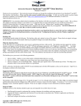
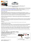
Instruction Manual for the eLogger V3
Patent Pending
Document Version 1.9, Model # MPRV3-CONN-100, MPRV3-LEADS-100, and MPRV3-LEADS-150
Thank you for your purchase! This instruction manual will guide you through the installation and operation of your eLogger.
Please read the entire manual carefully before proceeding. If, after you read the manual (including the Troubleshooting
sections!) you have further questions or problems, please visit our web support page for additional support options, at
http://www.eagletreesystems.com/Support/support.html. Note that the latest version of this manual is available in PDF form
from the Support page of our website.
Please also fill out the registration form at the end of this manual if you did not purchase your eLogger directly from Eagle
Tree Systems, so we can send you important update information.
Key Features
Here are a few of the features of the eLogger:
•
•
•
•
•
•
•
•
•
•
•
•
•
•
Logs pack current to +/- 100 amps (150 amps with MPRV3-LEADS-150) and voltage from about 5 volts to 70
volts
Current is measured with a true Hall Effects Sensor - NOT a resistance shunt like other units on the market!
Great for bench monitoring of battery charging also!
Supports the PowerPanel LCD Display
Accepts optional inexpensive sensors for three Temperatures, RPM (brushless, magnetic or optical), Airspeed,
Altitude, GPS, Servo Current, Throttle Movement, and more
Adjustable logging rate (1-10 samples/second) and lossless data compression for long log times
4 times the logging space of the eLogger V2, and all data is logged to permanent memory, which retains the data
even when the power is removed
Software computes Wattage, mAH, etc. for complete e-flight data.
Fully Compatible with Windows 7 (32 and 64 bit), Vista, 98SE, ME, Win2K and XP™
Weighs about 0.7 oz (20 grams). Versions with Wire Leads weighs slightly more.
Comes with our state of the art Windows virtual playback display and graphing
Powerful Graphing software has advanced charting features, such as amps vs volts
Internet Updatable firmware - as we add new features or (heaven forbid) have a firmware bug, the update is just a
download away! No need to ship hardware back and forth.
Full support for English and Metric units
Intended Uses
The eLogger was designed for use in Unmanned Radio Controlled models. It is intended to be used exclusively in model planes,
boats and cars. Using the eLogger for other purposes is not supported. Further, using the eLogger in situations where its use or
failure could result in loss of life, bodily injury or property damage is expressly prohibited.
Packing List
Your package should include the following: eLogger (either with integrated connectors or with wire leads), Custom USB Cable, and
CD-ROM.
Steps to Follow
Installation and use of the eLogger will be quite easy and enjoyable if you follow these few steps:
1.
2.
Read through the manual to understand the important warnings, determine what parameters you want to log, etc.
Install the eLogger in your model, as described in the eLogger Installation section below. Pay special attention to the
polarity and plug-in location of the sensors, since some of the plugs will fit in more than one location!
Copyright © 2003-2007 Eagle Tree Systems, LLC
Page 2
3.
4.
5.
Install and configure the Windows software as described in the Windows installation section below.
IMPORTANT: Bench and range test your model as described in the “Using the eLogger” section below.
Have fun!
Installation of the eLogger
IMPORTANT: Never let the sensor/USB prongs of the eLogger touch bare battery pack leads, exposed parts of your
ESC/BEC, or the motor casing!! Doing so could destroy the eLogger since these items may have high voltage present from
your battery pack, and void the warranty.
The below instructions and diagram guide you through the installation of the eLogger.
Connecting the eLogger to Your Model’s Power System
WARNING: High Voltages can cause electric shock. Be extremely careful when working
with high voltage packs! Work with high voltages at your own risk.
The eLogger is normally connected so that the connectors or leads marked “Batt” are connected to your battery pack, and the
connectors or leads marked “ESC” are connected to your ESC’s power input.
The red wires of the “wire lead” version of the
eLogger must be connected to the positive side of the load and source (normally the red wires). For measuring current/voltage
battery charging, it is ok to reverse the Batt and ESC connections, so that current is flowing “backwards” through the eLogger. The
eLogger will still measure current correctly in this mode!
IMPORTANT: Do not leave your model’s power system connected to the eLogger when the unit is not in use in the field.
Always disconnect the battery from your model when it is in storage.
IMPORTANT: With the Integrated Connector version of the eLogger, always ensure that the wiper prongs of all plugs are
not bent or damaged before connecting! A bent or damaged wiper prong could potentially collapse or fold over during
connection, and contact the other terminal of the connection, causing a short, or could result in an unreliable connection.
IMPORTANT: When first using your Connector version eLogger, make sure that the mating connectors you are using are
making good contact. One way to do this is to gently manipulate the connectors after they are all plugged in, to make sure
there are no loose connections.
Measuring Temperature with the eLogger
Copyright © 2003-2007 Eagle Tree Systems, LLC
Page 3
Up to three optional temperature sensors can be connected to the eLogger.
The temperature sensors are typically installed by placing the wire loop around the your battery pack, ESC, BEC, or other location, and
cinching it in place by pulling the two rubber stays snugly against the surface to be measured. Or, if you have the Micro temp sensor,
it can be slid under heat shrink, taped on, or otherwise affixed.
Plug the Futaba style connector of each temperature sensor into the eLogger as shown in Figure 1.
Note: the Temperature Sensor lead can be easily extended with a standard servo extension cable.
Measuring RPM with the eLogger, Using the Hall RPM Sensor with Magnets
NOTE: see the Brushless or Optical RPM Sensor instruction manuals if you are using one of those sensors.
Installing the optional Hall RPM sensor and magnets is the most challenging part of installation, but is relatively easy once a good
mounting location is determined. Refer to our website’s Flight support page at http://www.eagletreesystems.com for pictures of
example installations.
To install our magnets, first find a suitable location on your motor or drivetrain to attach either one or two small magnets and RPM
sensor. Typically, the prop washer or prop hub are ideal locations for planes, and the car’s axle shaft is good for car installation.
This will of course vary with the construction of the model. Make sure the magnets are mounted on some structure that doesn’t “flop
around,” as the magnets could hit the sensor in this case. The RPM sensor must be mounted so that it does not move around, and is
within 1-2 mm of the two magnets as they spin. On typical plane installations, there’s usually a place where the back of the sensor
can be glued to a flat surface under or over the hub which has the magnets mounted. The RPM sensor kit includes four magnets.
That provides you with up to 3 spares.
Installing Magnets
Once you have determined where to install the magnets, decide whether you will drill a hole so that the magnets will mount flush with
the surface, or if you will just glue the magnets to the surface. Though somewhat more difficult and permanent, mounting the
magnet flush with the surface is the best long term approach, since the mounting will be much more rugged, and the risk of imbalance
due to not mounting the magnets exactly 180 degrees apart is reduced. In fact, if the magnet is mounted flush in another metal
material, it is quite possible that no shaft imbalance will occur if you only mount one of the magnets total.
To flush mount the magnets, drill a hole just slightly larger than the diameter of the magnet size you choose, and of the same depth as
that magnet. If you decide to surface mount the magnets, thoroughly clean this area and lightly scuff it to improve adhesion. Glue
the magnets with the side marked with a red line facing inward (hidden), using epoxy, or other strong, suitable glue. It’s important
that the red line on the magnets faces away from the sensor once the sensor is installed. The magnets should be glued 180 degrees
apart to keep the shaft in balance.
WARNING: make sure that the magnets are glued sufficiently so that they will not detach and create a
hazard, and always wear safety glasses when your motor is running! It is also a good idea to put a piece
of heatshrink tubing or electrical tape around the magnets, to further secure them.
Using Existing Magnets
Note: if your motor already has magnets mounted for some other purpose, there’s a good chance you can use them. Take one of the
magnets included with the RPM sensor kit, and put that magnet up against the previously mounted magnet. If the red line of the
eLogger magnet faces down so that the sensor can be mounted facing the side of the magnet with no red line, mount the sensor with
the printed side toward the magnet. If the side of the magnet with the red line is visible when on top of the previous magnet, the
polarity is reversed. This should work correctly if you install our sensor backwards (printed side of sensor away from magnets).
Installing the RPM Sensor
Once the magnets are glued and completely dry, temporarily position the RPM sensor so that the side of the sensor with printing (or
a colored dot) is facing the side of the magnets WITHOUT the red line. The sensor now needs to be glued so that it is held
rigidly into position. Before gluing, put a small spacer (1-2 mm thick) between the sensor and one of the magnets to ensure proper
spacing.
If desired, a small piece of brass tubing can be glued or heatshrunk to the back of the sensor to ease mounting and increase stability.
Copyright © 2003-2007 Eagle Tree Systems, LLC
Page 4
After the sensor is glued and completely dry, remove the small spacer and rotate the drive train or propeller to ensure complete
freedom of movement. Also make sure that the sensor won’t vibrate and come in contact with the magnets during operation. If this
happens, the sensor will be destroyed, and the eLogger could be damaged.
Once these steps are complete, plug the Futaba style connector on the sensor into the eLogger as shown in figure 1.
standard Futaba style servo extension cable can be used to lengthen the RPM sensor wire if needed.
Note that a
Using Existing RPM Sensors
Several of our customers have been able to use existing RPM sensors, such as governors or turbine sensors, with our products.
following steps must be followed:
The
1) Determine the “pinout” of the existing sensor. Compatible sensors will have Power, Ground, and Signal connections. The
eLogger’s RPM pinout, from left to right, is: Power (black wire), Ground (red wire), Signal (white wire).
2) Devise a “Y” cable to connect your existing sensor to it’\s connection, and also to the eLogger’s RPM connection. NOTE:
Power for the sensor should come only from the connection the sensor is normally plugged into. So, only Gound and Signal
wires should be routed from the existing sensor to the eLogger. The power wire of the Y cable between the sensor and the
eLogger should be cut before connecting it to the eLogger. This is necessary to avoid connecting the power of the existing
sensor connection to the eLogger’s power connection.
3) Thoroughly test the system to make sure the sensor still works with whatever it was originally connected to, after Y’ing to the
eLogger.
Installing a Secondary RPM Sensor
A second MODIFIED Brushless RPM sensor can be plugged into the eLogger’s THROTTLE input, for measuring RPM of multiple
motors.
NOTE: the Optical and Hall Effects RPM sensors CANNOT be used as secondary sensors, and will be damaged if plugged into any
port other than the RPM port. Only the brushless RPM sensor can be used for secondary RPM.
To measure secondary RPM, the RPM sensor must be modified as follows:
• Carefully pry back the plastic tabs that hold the RED and BLACK pins in the RPM sensor connector, and remove the red and
black pins.
• Replace the red pin where the black pin was, so that the pin order in the connector is RED, OPEN, WHITE.
• The second RPM sensor plugs into the throttle port with the red wire toward the label side of the logger.
• The black pin (left detached from the connector above) connects to the upper “Tmp 3” pin, nearest the label.
NOTE: The second RPM channel is automatically set up with the same sensor type and gear ratio as the primary RPM.
important that the same type of sensor be used for primary and secondary RPM.
The secondary RPM sensor(s) are logged and displayed on the screens with the other parameters, as described below.
Monitoring your Model’s Throttle Position with the eLogger
Connecting the Throttle Servo Y-Cable to
your Throttle, and to the eLogger
IMPORTANT: Make sure you connect the
battery pack to the eLogger only AFTER
connecting the throttle Y cable to the eLogger
(and all other connections). The eLogger logs
servo positions by measuring the pulses coming from
your receiver to the throttle servo, via the optional Y
cable. The Y Cable has 3 connections. The
“Futaba” male plug (at the “base of the Y”) connects
to the eLogger as shown in Figure.
The universal
male and female plugs of the Y cable connect to your
receiver’s throttle channel, and to your throttle servo,
respectively. See Figure 2 for connections of the Y
cable to your Receiver and Servo.
Copyright © 2003-2007 Eagle Tree Systems, LLC
So, it’s
Page 5
Note that when the Y cable is connected to your receiver, there is a common ground connection
produced between your receiver and your battery pack, which is also connected to the eLogger. This will bypass
any optical or other isolation that might be built into the ground connections of your ESC. We are aware of no
issues with connecting a wire between battery ground and receiver ground in these cases, but proceed with caution (at
your own risk) as there is the unlikely possibility that your hardware may be damaged by such a connection, and make
sure you do an antenna down range check after making this change.
Installing and Using the Windows™ Application
Installing the Windows Application
The supplied Windows application is compatible with USB equipped PCs running Windows 7, Vista, XP, Windows 98SE,
Millennium, or Win 2K. The application is not compatible with Windows 98 Original Edition (Gold), or NT 4, even if the PC has
USB support.
NOTE: the application included on CD with the unit was current at the time of manufacture. Please check our eLogger Support page
on http://eagletreesystems.com to see if there is a newer version of the Windows application which may have addressed issues you
could encounter.
To install the application, just place the CD in the CD-ROM drive. If AutoPlay is enabled on your PC, the setup program should run
automatically. If it does not run, click on My Computer, click on the icon for your CD-ROM drive, and click on the “setup.exe”
application icon in the drive window.
Follow the Setup Wizard to install the eLogger application. Once installation is complete, the eLogger may be launched either from
its Desktop Icon, or by choosing the eLogger application from the Start->Programs->Eagle Tree Systems folder.
Setting up the eLogger with the Application
Once the application is installed, follow the above steps to launch it. The first time the application is launched, the New Model
Wizard will be invoked.
The Wizard will prompt you to install the eLogger using the supplied USB cable.
IMPORTANT: Make sure you connect the custom USB plug with the correct polarity, and into the correct
connector on the eLogger, as shown in Figure 1.
When you do this for the first time, the behavior will be different depending on which version of Windows you are using:
Windows 98™: The eLogger and application are not compatible with Windows 98.
Windows 98SE™ and Windows Millennium™: When the eLogger is first connected to the USB port, the New Hardware Wizard
will likely appear. Follow the steps in the Wizard, choosing the options to allow Windows to find the appropriate drivers for the
eLogger – these drivers are built into Windows. If the devices you already have on your computer haven’t required the installation of
the USB drivers, Windows will prompt you for your Windows CD to copy over the drivers. Once this process is complete, you may
be asked to reboot the system. Reboot at this point, then relaunch the eLogger Application, and the New Model Wizard should start
up again.
Windows 7™, Windows Vista™, Windows 2000 ™ and Windows XP ™: When the eLogger is first connected to the USB port,
Windows should automatically install the correct drivers without prompting you. If you should receive a Windows prompt, however,
do what it says.
Once the eLogger is correctly discovered and installed by Windows, continue on with the New Model Wizard, relaunching the
Windows application after reboot if necessary.
Telling the eLogger what to Log
The first time you run the app, you will be prompted to choose what parameters you wish the eLogger to record. The more items
you log, the less record time will be available. A description of the parameters is below:
Copyright © 2003-2007 Eagle Tree Systems, LLC
Page 6
Electric Motor Voltage: If this option is selected, Pack Voltage is logged.
Electric Motor Current: If this option is selected, Pack Current is logged.
RPM Sensor A: If this option is selected, the eLogger logs the RPM of your model, if you have installed the optional RPM sensor.
Temperature 1: Choose this option if you want to record temperature from an optional temperature sensor.
Temperature 2: Choose this option if you want to record temperature from a secondary optional temperature sensor.
Temperature 3: Choose this option if you want to record temperature from a third optional temperature sensor.
Throttle Movement: Choose this option if you want to record signals from the optional throttle servo Y cable.
Airspeed: Choose this option if you want to record airspeed with the optional Airspeed MicroSensor.
Altitude: Choose this option if you want to record altitude with the optional Altitude MicroSensor.
Servo Current: Choose this option if you want to record servo current with the optional Servo Current MicroSensor.
All GPS Parameters: Choose this option if you want to record GPS Parameters with the optional GPS Expander.
Spektrum™ AR9000™ Flight Log Interface: Choose this option if you want to record AR9000™ or JR 921™ receiver
performance data, with the optional Spektrum™ cable.
Setting the “Stop on Full” Feature
After you complete the New Model Wizard for the first time, you will be prompted to choose whether you want the eLogger to write
over its data when its buffer becomes full, or to stop when the eLogger is full. NOTE: You can change this setting later from the
Hardware menu of the Windows application. If you select “Stop on Full” the eLogger’s LED will flash two flashes in a row when
the buffer is full.
Setting the “Set Capture Rate” Feature
The eLogger can be adjusted to capture data in during the recording session at five different rates. The faster the capture rate, the
more data is obtained, but at the expense of record time. The default rate, ten samples/second, gives the best resolution, but the
record times will be lower than with lower sample rates. You may find that you can get plenty of record time even with the highest
capture rate setting, however.
Note: You can change this setting later from the Hardware menu of the Windows application.
A note on record time: The eLogger uses advanced data compression to get the most data recorded as possible. When your model is
sitting idle before or after the session with the battery turned on, the eLogger is still capturing data, but since not much is changing
very little data is recorded. But when the model is active more data is being recorded.
Setting the “Choose What to Display on the PC Screen” Feature
The eLogger Application can display several model parameters in both numeric and instrument format. Select the parameters you
wish the Application to display with this dialog box. Note that some of the parameters require optional accessories, available from
Eagle Tree Systems.
Note: Select the “Metric” checkbox on this dialog if you want metric operation.
Also, you can change these settings later from the Software menu of the Windows application.
Configuring and Calibrating the Throttle Function of the Expander with the Windows
Application
Copyright © 2003-2007 Eagle Tree Systems, LLC
Page 7
Calibrating Throttle Movement
It is not absolutely necessary to calibrate the throttle function. The advantages of calibration are that the throttle gauge and graphs
will range from zero (closed throttle) to approximately 210 (maximum throttle), as you move your throttle between its extremes. If
you do not calibrate, the throttle gauge and graphs will still show throttle movement, but the graph could be inverted if you have the
throttle servo reversed, and will not go from zero to 210.
To calibrate the throttle with your model, first connect the throttle Y cable as described above, and connect the eLogger to your PC
via the USB cable. Then, click “Calibration, Calibrate Throttle.” The Calibrate Throttle Wizard will then explain the calibration
procedure.
Using the eLogger
Once the eLogger and application is installed, it’s almost time to operate! Please read the important information below on
eLogger operation before using it at the field in your model.
It is extremely unlikely that the eLogger unit will affect your model’s radio range. But, as always after making an electronics change
to your model, it is very important that you range and function test your model once the eLogger is installed to ensure that there is no
impact on your system. Make sure that your “antenna down” operating range is within the manufacturer’s specifications. See your
Radio owner’s manual for the correct procedure for your equipment. DO NOT OPERATE IF YOUR MODEL DOESN’T PASS
THE ANTENNA DOWN RANGE CHECK.
Additionally, you need to make sure that your Model’s power system is working correctly after adding any new hardware in-line, like
the eLogger. This is especially critical in high amperage/voltage installations, of course. It’s important that you safely run your
model in an extended stationary “bench” test, similar in duration and power usage to your most aggressive modeling, to ensure there
are no problems with any connections, etc. DO NOT OPERATE YOUR MODEL IF YOU HAVE PROBLEMS DURING THIS
EXTENDED STATIONARY TEST!
The eLogger’s LED
The eLogger’s LED indicates the device’s status.
Once the eLogger is powered up in your model, it will repeatedly flash a sequence of one, two or three flashes every second or so.
This flash rate is longer or shorter depending on the capture rate. This flashing indicates the following:
One Flash - The eLogger is actively recording. This is the normal power-up state.
Two Flashes – The eLogger’s buffer is full, or you have enabled logging triggers and the logger is not yet triggered. Note that the
eLogger will pause when the buffer is full only if you have selected the “stop on full” mode described above, when the memory is
filled to capacity with data.
Three Flashes – The eLogger is connected to your PC’s USB connector, and has been recognized by the PC.
After Your Recording Session
After operating your model with the eLogger, you can either remove the eLogger from your model and take it to your PC, bring the
model with the eLogger still in it to your PC, or (if you’re lucky) use a Laptop and connect to the eLogger in the field.
After you connect the eLogger to your PC’s USB interface, the LED should indicate USB connectivity with three repeating flashes as
described above.
Once the eLogger is connected, launch the Application and click on the “Download” button.
Buffer into the Application for playback and saving.
This will load the eLogger’s Data
Use the play controls to play back the data. Note that the Slider can be dragged with the mouse by clicking and holding it then
moving it to the desired position.
The application displays the following information:
•
Notifications – this window displays messages about the recording. The three most common messages are:
Copyright © 2003-2007 Eagle Tree Systems, LLC
Page 8
Startup/Reset Detected – this indicates that the eLogger has been turned on at the time specified
eLogger low battery restart – this indicates that the eLogger has ‘rebooted’ because the power momentarily dropped
below around 4.5 volts. See the troubleshooting section if you frequently see this message.
Length/Progress – when stopped, this readout indicates the total recording length. When playing back, this meter indicates
current time into the session.
Graphical and/or Numeric Pack Voltage – The application displays the current or max (when playback is stopped) pack
voltage readings in either gauge or numeric format.
Graphical and/or Numeric Pack Current – The application displays the current or max pack amperage readings in either
gauge or numeric format.
Pack Wattage – this gauge indicates the pack wattage during playback.
Cumulative Amp-Hours – this numeric display indicates the cumulative AH used
Graphical and/or Numeric Temperatures – The application can display up to two Temperature readings in either gauge or
numeric format.
Graphical and/or Numeric RPM – The application displays RPM readings in either gauge or numeric format.
Graphical and/or Numeric Speed(Cars Only) – The model’s speed, as computed from the RPM, can be displayed
graphically and numerically.
o
o
•
•
•
•
•
•
•
•
Multiple Session Support
Depending on the length of your modeling sessions, it is often possible to record multiple runs into the eLogger without having to
clear the buffer or overwrite data. The eLogger application will split multiple sessions automatically for you. By clicking the
“Sessions” option in either the playback or graphing pages of the app, you can display a separate session, or all sessions
simultaneously. When graphing all sessions simultaneously, vertical gray bars on the graph indicate where sessions start.
Note that a new session is created in the logger each time it is powered off and on.
Saving eLogger Log Files
After downloading session data, if you wish to save the data to play back later or to share with friends, save the file with the File>Save Recorder File menu. Note that the file is saved with a .FDR extension by default.
Combining Log Files
To combine two or more log files, simple open one of them using “File, Open Recorder File” and then combine with others by
selecting “File, Combine Recorder Files.”
USB Live Mode Bench Testing
When the eLogger is installed in your power system, and is also connected to your PC via the USB cable, clicking the Live Mode
button in the Windows application will cause the numeric displays and gauges to display data live. Live Mode sessions can be
recorded on the PC. To set up Live Mode recording, click “Software, Set Live Mode Options.” If Live Mode recording is enabled,
you will be prompted to save the recorded data when you stop live mode by clicking “Stop.”
Also, note that real time strip charting is also supported in Live Mode. To see real time strip charts, first turn on Live Mode
recording. Then, click “Graph Data” to launch the graph. Configure the parameters you want to see on the chart, and then click the
Live Mode button. Live data will be graphed on the chart!
Graphing/Spreadsheet Compatibility
The eLogger application has extensive graphing capability built in. Just click “Data, 2D Chart” in the software to graph loaded data.
Note that individual sessions of the file can be graphed separately, or side by side, by clicking one or more sessions to graph in the
“Sessions” menu. Side by side graphing lets you compare performance across different laps, or with different log files if the
“Combine Recorder Files” option is used as described above. Click on the HELP button on the graphing page for more information
on graphing.
Also, the eLogger’s Data File is compatible with Excel ™ spreadsheet software, and perhaps other spreadsheet brands. Using
Excel™ is useful for graphing the data output from the eLogger.
To load in Excel, save the data file from “File->Save Recorder File,” and in Excel™ choose File->Open, and select “All Files” in the
“Files of Type” box. Navigate the Excel dialog box to the location you saved the .FDR data file, and click on the filename. Excel
should then bring up the “Text Import Wizard”. Choose the “Delimited” option, and on the next page choose “Delimited with
Spaces”. The data should then load correctly in Excel.
Copyright © 2003-2007 Eagle Tree Systems, LLC
Page 9
The format of each line of data in the file is:
First Line: Model Name
Second Line: Data about your Model’s setup. This line is needed to allow sharing of your session log files with others.
Third line: header indicating what each of the data fields represents. These columns are:
Milliseconds
Amps*100
GPSSpeed
IsEvent
Temp1*10
GPSCourse
EventError
Temp2*10
GPSDist
EventData Altitude
Temp3*10 RPM
GPSUTC NumSats
Airspeed ServoCurrent*100
RPM2
GPSLat
GPSFlags
Throttle
GPSLon
PackVolt*100
GPSAlt
If “IsEvent” is 1, the record contains event data as well as regular data. Typical events are power-up (restart), and servo glitches.
Ignore the non-event fields when IsEvent is set to 1.
Event Codes in the “EventCode” field are as follows. Note that codes other than those below should be reported to Eagle Tree
Systems:
9 = ERROR_RESTART: The eLogger has been started or restarted (power was applied)
18 = ERROR_GPS_DATA_PACKET: GPS Data was received from the GPS Expander,
27 = ERROR_SPEKTRUM_DATA_PACKET: Data was received from the AR9000 Interface
Milliseconds indicates when each record was collected, in Milliseconds since the eLogger was turned on.
Email us if you need more information on the file format.
Happy Modeling!!
Troubleshooting
Below is a list of problems that may be encountered, and steps to remedy them.
A good first step to troubleshooting, if you are able to connect your eLogger to your PC, is to download our latest software and update
the eLogger’s Firmware via “Hardware, Firmware Control.” Doing this will ensure that you have the latest software and firmware
available.
If your particular issue is not addressed by this update, or by the suggestions below, please visit our web support page for additional
support options, at http://www.eagletreesystems.com/Support/support.html.
Issue: My PC does not recognize the eLogger.
Solution: Try to eliminate the problem in the following ways:
o Disconnect all other USB peripherals from your PC (if possible) and try the eLogger again.
o Try the eLogger on a different PC. If it works, there may be a misconfiguration with your PC.
o Try the eLogger with a different USB cable, if you have one. If this works, your cable has been damaged.
o Try rebooting your PC – occasionally USB support gets disabled with some PCs.
o Try the other USB connector on you PC if it has two.
o Ensure that USB is enabled within your Operating System by checking in Device Manager. You’ll need to see your
Windows™ documentation to determine how to do this on your particular OS version.
Issue: RPM is not working correctly (note: also see the Optical or Brushless RPM Sensor instruction manual if you are using the
Optical or Brushless RPM Sensor)
Solutions:
• With the magnetic sensor, check to make sure your sensor to magnet gap is around 2mm or less.
• Check the magnet polarity mounting. The magnet should have been glued so that the red line faces down, away from the
sensor, and the writing on the sensor faces the magnet. If you inadvertently glued the magnet so that the red line is facing
UP, flip the sensor over so the "non printed" side faces the magnet.
• Make sure that under Choose What to Log in the app, you have checked RPM.
• Make sure that the RPM sensor is plugged into the correct slot on the eLogger
• Connect the eLogger to the computer and launch the Windows Application. Then, click the “Live Mode” button. Make
sure that the RPM gauge is displayed, and spin the magnets, or wave the magnets by hand in front of the sensor. Try both
sides of the magnets and both sides of the sensor. See if the RPM reading jumps.
Issue: I have a fully charged battery, but the eLogger frequently shows “Low Battery Restart” Notifications when playing back data.
Copyright © 2003-2007 Eagle Tree Systems, LLC
Page 10
Solution: The eLogger shuts down immediately if the power goes below around 5 volts for more than a few
milliseconds, and logs this occurrence when the power returns to above 5 volts. If your battery’s voltage frequently drops this low,
you may be underpowered, and may want to consider getting a bigger battery.
Issue: the Current or Voltage being logged by the eLogger appears incorrect.
Solutions:
• Make sure that the parameters you wish to log are checked under “Hardware, Choose Parameters to be logged in Recorder”
• If the current being logged by the eLogger appears to be incorrect, connect a battery pack to the eLogger, and connect the
eLogger to USB. Then, click “Calibration, Rezero Current Sensors” to rezero your sensor. Make sure that no ESC or other
load is connected to the eLogger during this step! Note that this calibration step is done at the factory before shipping, but it
may be possible for drift to occur after the eLogger has been in operation for some time.
• If the current readings appear to be inaccurate even after you have completed the “Calibration, Rezero Current Sensors” step
above, or if voltage readings appear to be slightly different than another meter you are accustomed to, it is easy to calibrate
the eLogger readings to your other meter’s readings if desired. This is done by choosing “Advanced, Calibrate Pack
Voltage and Amperage” and entering the values your meter reads, and the eLogger reads. If you don’t desire to change the
calibration on, say, voltage, but wish to change it for amperage, just leave the voltage fields as 0, and the calibration for
voltage will not change. The eLogger is factory calibrated using a highly accurate current and voltage measurement tool.
• If the eLogger appears to be reading highly inaccurate voltages or currents, the first thing to try is to clear all calibration.
This is done running the calibration tool as described above, but entering the same values for the problem measurement. For
example, if amperage is way off, enter the same value (say, 5.0) for both the eLogger amperage and the “my other meter”
amperage, which will clear all internal and user calibration.
Issue: the temperature appears to be logged incorrectly.
Solutions:
• Make sure that the parameters you wish to log are checked under “Hardware, Choose Parameters to be logged in Recorder”
Issue: Throttle Movements are not correct, or the throttle cannot be calibrated.
Solutions:
• Ensure you have connected the Y cable as shown in Figure 1.
• Complete the Throttle Calibration step as described above.
• Make sure you are logging throttle movements in the eLogger.
Issue: The eLogger shuts off or the LED flashes rapidly when used with the GPS Expander.
Solutions:
• The GPS Expander draws significant current from the eLogger. When the eLogger is powered by a higher voltage pack, such
as an 8s or larger pack, or a pack above 30 volts, the eLogger’s regulator may shut off after a short period when used with the
GPS. Please use our “Battery Backup Harness”, part number CAB-BAT-BACK, to provide supplemental power to the
eLogger, if you encounter this issue.
eLogger Specifications
Voltage Measurement: approx 5V to 70V
Voltage Resolution: approx 0.02V
Current Measurement: up to 100 Amps, (150 Amps with the MPRV3-LEADS-150)
Current Resolution: approx 0.02 Amps (0.035 Amps with the MPRV3-LEADS-150)
Current Draw: approx 30 mA with no sensors
Weight: Unit with Integrated Connectors: approx 0.7oz (20 grams), 100 amp unit with Wire Leads: 0.9 oz (25 grams)
Temperature: Dual inputs, 0 degrees F to 424 degrees F (three temperature inputs)
RPM range: approx 100 RPM to 50,000+ RPM
Units of Measure supported: English and Metric
Measurements: approx 2.25” x 1” x 0.5” (57mm x 28mm x 13mm) including sensor pins
Length of Wires with Wire Lead Version: approx 2.5” (65mm)
Record Time: Varies with sample rate, parameters being recorded, and “activeness” of the model. Anywhere from around 45
minutes to many hours is attainable depending on these settings.
Limited Warranty
Eagle Tree Systems, LLC, warrants the eLogger to be free from defects in materials and workmanship for a period of one (1) year
from the date of original purchase. This warranty is nontransferable. If your unit requires warranty service during this period, we
will replace or repair it at our option. Shipping cost to us is your responsibility.
Copyright © 2003-2007 Eagle Tree Systems, LLC
Page 11
To obtain warranty service, contact us by phone, fax or email to request an RMA number. No returns will be accepted
without this number.
This limited warranty does not cover:
•
•
The Software included with the eLogger. See the Software license agreement for more information on Software restrictions.
Problems that result from:
o External causes such as accident, abuse, misuse, or problems with electrical power
o Servicing not authorized by us
o Usage that is not in accordance with product instructions
o Failure to follow the product instructions
THIS WARRANTY GIVES YOU SPECIFIC LEGAL RIGHTS, AND YOU MAY ALSO HAVE OTHER RIGHTS WHICH VARY
FROM STATE TO STATE (OR JURISDICTION TO JURISDICTION). OUR RESPONSIBILITY FOR MALFUNCITONS AND
DEFECTS IN HARDWARE IS LIMITED TO REPAIR AND REPLACEMENT AS SET FORTH IN THIS WARRANTY
STATEMENT. ALL EXPRESS AND IMPLIED WARRANTIES FOR THE PRODUCT, INCLUDING, BUT NOT LIMITED TO,
ANY IMPLIED WARRANTIES AND CONDITIONS OF MERCHANTABILITY AND FITNESS FOR A PARTICULAR
PURPOSE, ARE LIMITED IN TIME TO THE TERM OF THE LIMITED WARRANTY PERIOD AS DESCRIBED ABOVE. NO
WARRANTIES, WHETHER EXPRESS OR IMPLIED, WILL APPLY AFTER THE LIMITED WARRANTY PERIOD HAS
EXPIRED. SOME STATES DO NOT ALLOW LIMITATIONS ON HOW LONG AN IMPLIED WARRANTY LASTS, SO THIS
LIMITATION MAY NOT APPLY TO YOU.
WE DO NOT ACCEPT LIABILITY BEYOND THE REMEDIES PROVIDED FOR IN THIS LIMITED WARRANTY OR FOR
CONSEQUENTIAL OR INCIDENTAL DAMAGES, INCLUDING, WITHOUT LIMITATION, ANY LIABILTY FOR THIRDPARTY CLAIMS AGAINST YOU FOR DAMAGES, FOR PRODUCTS NOT BEING AVAILABLE FOR USE, OR FOR LOST
DATA OR LOST SOFTWARE. OUR LIABILITY WILL BE NO MORE THAN THE AMOUNT YOU PAID FOR THE PRODUCT
THAT IS THE SUBJECT OF A CLAIM. THIS IS THE MAXIMUM AMOUNT FOR WHICH WE ARE RESPONSIBLE.
SOME STATES DO NOT ALLOW THE EXCLUSION OR LIMITATION OF INCIDENTAL OR CONSEQUENTIAL DAMAGES,
SO THE ABOVE LIMITATION OR EXCLUSION MAY NOT APPLY TO YOU.
Product Warranty Registration
Registering your product means that we can send you important updates and other notifications. Please fill out this form (or a copy)
and mail or fax it to Eagle Tree Systems. Or, email the info to [email protected]. Note that if you purchased your item
directly from Eagle Tree Systems, this is not necessary.
Eagle Tree Systems Warranty Product Registration:
Name:__________________________________________________________________________
Address: ________________________________________________________________________
Phone: ________________________________ Email: ___________________________________
Product(s) Purchased: ________________________
Date Purchased:______________________
Where did you purchase your product?_________________________________________________
Where did you hear about our product? _______________________________________________
Any features or additions you would like to see? _________________________________________
Copyright © 2003-2007 Eagle Tree Systems, LLC