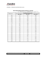
1
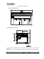
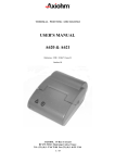
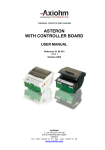
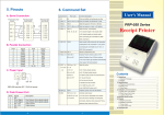
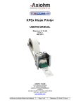
THERMAL PRINTER COMPONENTS
CMDT/RMDT
12V MINI-PRINTER PREMIUM SERIES
60 mm PRINTER MECHANISM
USER MANUAL
Reference: 31 09 615
Issue D
February 2010
!"
##$
% % %
&'!"
##$
% %
EVOLUTIONS
Date
10/2008
03/2009
09/2009
02/2010
02/2010
Issue
Z
A
B
C
D
Modifications
Creation
Modification of chapter: “Recommendations for paper”
Addition of RM Version for high grammage paper
Add recommendation about ESD discharge
Addition of recommendations concerning the opening of the mechanism
CM/RMDT Mini-Printer Premium Series User Manual
Page 1/38
Reference: 31 09 615 / D
IMPORTANT
This manual contains the basic operations for running your printer.
Read it carefully before using your printer.
Pay special attention to the chapter “Recommendations”.
CM/RMDT Mini-Printer Premium Series User Manual
Page 2/38
Reference: 31 09 615 / D
CONTENTS
1 UNPACKING.......................................................................................... 5
2 OVERVIEW ............................................................................................ 5
3 MECHANICAL SPECIFICATIONS..................................................... 7
3.1
General description............................................................................. 7
3.2
Dimensions of the complete mechanism ...................................... 7
3.3
Mechanical views................................................................................. 7
4 ELECTRICAL SPECIFICATIONS .................................................... 11
4.1
ESD discharge recommendation ................................................... 11
4.2
Nominal Power supply...................................................................... 11
4.3
Nominal Consumption...................................................................... 12
4.4
Description of print head ................................................................. 12
4.4.1
Function of each 64 bit IC (integrated circuit) ................. 13
4.4.2
Operation of the complete module.................................... 14
4.4.3
Electrical specifications of 64-BIT LSI driver ................... 15
4.4.4
Print head Connection......................................................... 17
4.5
Bipolar paper feed motor................................................................. 19
4.5.1
General specification........................................................... 19
4.5.2
Induction sequence and timing .......................................... 20
4.5.3
Paper Motor Acceleration Ramp-Up ................................. 21
4.6
Bipolar cutter motor .......................................................................... 21
4.6.1
Overview................................................................................ 21
4.6.2
General specification........................................................... 21
4.6.3
Connection ............................................................................ 21
4.6.4
Induction sequence ............................................................. 22
4.6.5
Cutter Initialization ............................................................... 22
4.6.6
Cutter Motor Acceleration Ramp-Up................................. 24
4.6.7
Cutter Driving Chart............................................................. 24
4.7
Cutter micro-switch specifications ............................................... 26
4.7.1
General specification........................................................... 26
4.7.2
Connection ............................................................................ 26
4.8
Opto-sensor specification ............................................................... 26
4.8.1
Electrical characteristics ..................................................... 26
4.8.2
Connection ............................................................................ 27
4.8.3
External circuit ...................................................................... 27
5 PRINTER CONTROL TECHNIQUES .............................................. 28
5.1
Mode 1................................................................................................... 28
5.2
Mode 2................................................................................................... 29
5.3
Mode 3................................................................................................... 30
CM/RMDT Mini-Printer Premium Series User Manual
Page 3/38
Reference: 31 09 615 / D
6 RECOMMENDATIONS ...................................................................... 31
6.1
Mechanical recommendations ....................................................... 31
6.2
Housing design recommendations ............................................... 31
6.3
Energizing & de-energizing printer ............................................... 32
6.4
Printing recommendations.............................................................. 32
6.5
Recommendations for paper .......................................................... 32
6.6
General.................................................................................................. 33
6.7
Cleaning recommendations ............................................................ 33
6.8
Special recommendation for cutter .............................................. 34
7 APPENDICES ...................................................................................... 35
7.1
APPENDIX 1: Thermistor specifications...................................... 35
7.2
APPENDIX 3: Heating time and historical control..................... 37
CM/RMDT Mini-Printer Premium Series User Manual
Page 4/38
Reference: 31 09 615 / D
1 UNPACKING
Each printer mechanism is packaged in an antistatic bag.
Observe precautions while handling in electrostatic protected areas.
2 OVERVIEW
Based on static thermal printing technology, the RM series is a family of user-friendly, highly
reliable devices which have been specially designed to fit in minimum space.
CMxx: Printer only or printer with optional tear bar cover.
RMxx: Printer with robust guillotine cutter.
Characteristics:
Very small size printer and cutter
Silent mechanism
Option of 4 dots/mm or 8 dots/mm print-heads
Easy to connect (only one connector for motor, print head, opto-sensor and cutter)
Front and bottom paper introduction possible
SUMMARY OF PRINTER SPECIFICATIONS
ITEM
Printing method
VALUE
UNITS
Static thermal dot line printing
-
56
mm
150 (1)
mm/sec
Auto-load
60
By opto-sensor
80
JUJO AF50KSE3
mm
µ
448
8
dots/mm
1
-
0.125
mm
By Thermistor
Opto-sensor
-
25% max at 25°C
22 % max at 50°C
(see chapter Printing
recommendations)
%
Printing width
Printing speed max
Paper loading
Paper width
Paper empty detection
Maximum paper thickness
Recommended paper
Number of resistor dots
Resolution
Number of steps / dot line
Paper feed / dot line
Head temperature detection
Out of paper detection
Maximum duty cycle
(to avoid motor temperature
rise)
CM/RMDT Mini-Printer Premium Series User Manual
Page 5/38
-
Reference: 31 09 615 / D
SUMMARY OF PRINTER SPECIFICATIONS (continued)
ITEM
VALUE
UNITS
- 30 to + 70
- 20 to + 60
°C
°C
20 to 85 no condensing
%
Operating voltage range Vcc
(logic)
4.5 – 5.5
V DC
Operating voltage range Vch
(dot)
11 – 15.2
V DC
17.9
A
Current consumption:
V ch (at nominal value)
35.5 mA
mA per resistor dot
”On ”
Current consumption:
V cc (at nominal value)
100
µA
Current consumption:
stepping motor for paper feed
515
mA
Current consumption:
stepping motor for cutter
715
mA
10E8
100 Km
1 000 000 cuts
with recommended paper
pulses
Km
-
Storage temperature range
Operating temperature range
Relative humidity range
(operating)
Peak print head current
(all dots "on" at nominal value)
Electrical life time (2)
Mechanical life time (2)
Cutter life time (for RMxx)
Over all dimensions:
Height
32 (CM)
36
42.1 (RM)
mm
74.5 (RM)
65.75
mm
mm
(CM w/cover)
Width
Depth
74.5 (CM)
61 (CM)
62.5
(RM)
(CM w/cover)
Weight (average) (without
paper roll)
140 (CM)
250 (RM)
g
(1) Max print speed will depend on paper reference, power supply and dots ON ratio.
CM/RMDT Mini-Printer Premium Series User Manual
Page 6/38
Reference: 31 09 615 / D
3 MECHANICAL SPECIFICATIONS
3.1 General description
The mechanism consists in:
- Plastic chassis
- Robust guillotine cutter (with relevant motor and switch) for RM versions
- Stepping motor
- Gear train
- Print head
- End of paper opto-sensor
3.2 Dimensions of the complete mechanism
Height:......................................
Depth:.......................................
Width (without rewinder option)
Weight:.....................................
32 (CM) / 36 (CM with cover) / 42.1 mm (RM)
61 (CM) / 62.5 (CM with cover) / 65.75 mm (RM)
74.5 (CM) / 74.5 mm (RM)
140 (CM) / 250 g (RM)
3.3 Mechanical views
Fig. 1 CM without cover dimensions
CM/RMDT Mini-Printer Premium Series User Manual
Page 7/38
Reference: 31 09 615 / D
Mechanical views (continued)
Fig. 2 CM with cover dimensions
Fig. 3 Side view with cover
10.1
42.1
32
1.75
61
64
CM/RMDT Mini-Printer Premium Series User Manual
Page 8/38
Reference: 31 09 615 / D
Mechanical views (continued)
Fig. 4 front view with cover
74.5
Fig. 5 bottom view / fixing holes
Use self-threader screws for plastic, the fixing holes diameter being 2.5 mm, use a maximum
diameter
of 3 mm for screws and a maximum depth in chassis of 7 mm (from the external edge of holes).
CM/RMDT Mini-Printer Premium Series User Manual
Page 9/38
Reference: 31 09 615 / D
Mechanical views (continued)
Fig. 4 cutter top view
12.5
paper exit wdth : 60.5
Fig. 5 Opto- sensor position
The position of the end of paper opto-sensor relatively to the paper allows top off form
detection
Paper sensitive layer
Paper non sensitive layer
7
7
paper path
direction
5
5.5
front paper inlet
CM/RMDT Mini-Printer Premium Series User Manual
rear paper inlet
Page 10/38
Reference: 31 09 615 / D
4 ELECTRICAL SPECIFICATIONS
4.1 ESD discharge recommendation
Due to high speed printing, it’s very important to connect the mechanism at the ground
To avoid ESD discharge which may damage the controller Board!
You can use an Axiohm KIT A3105306 for example (length 160mm)
wheel available
from the side
Ground
connection
screw wheel available
from the top
Example of connection with
CompactII board
4.2 Nominal Power supply
Value
Units
Print head:
Logic (Vcc)
Dot line
5
12
V DC
V DC
Stepping motor
12
V DC
CM/RMDT Mini-Printer Premium Series User Manual
Page 11/38
Reference: 31 09 615 / D
4.3 Nominal Consumption
RMDV
Units
40
mA
Logic current / dot (Vcc)
100
µA
Stepping Motor (2 activated
phases) for paper feed
515
mA
Stepping Motor (2 activated
phases) for versions with
cutter (RMxx)
900
mA
Maximum instantaneous
current per dot line (at 12V)
17.9
A
Print head:
Heating
current / dot
(Vch) at nominal values
4.4 Description of print head
Driver chips
(64 bit BiCMos LSI)
Nominal dot resistance
Nominal dot energy
(in standard conditions)
Max printing speed (with 12V power
supply)
(with dot historical control)
CM/RMDT Mini-Printer Premium Series User Manual
Value
UNIT
7
-
300 (± 5 %)
ohms
0.17
mJ/dot
150
mm/sec
Page 12/38
Reference: 31 09 615 / D
4.4.1
Function of each 64 bit IC (integrated circuit)
Vch
1
2
3
4
...... (OUTPUTS)....
62
63
64
Line of resistor dots -
Output
Enable (OE)
OE1
OE2
Strobe
64 bits buffer
registers
Serial
Input (SI)
64 bits shift
registers
CLOCK
SERIAL
OUTPUT (SO)
Fig.6 Driver IC schematic
These circuits are supplied by
5V +/- 5% logic voltage
Each circuit features
64 open collector transistors
64-bit shift register
64-bit memory register
Each circuit controls
64 resistor dots on the print head
The heating element power supply VCH is not connected to the Driver ICs but only to the
resistive line of dots itself. The driver ICs are connected via a pattern of high current gold
interconnecting traces to the line of resistor dots.
The dot line is of the interdigitated type, in order to maintain the tight definition of the dot
geometry and resistance. In such a scheme the heating element power supply VCH forms a
‘comb’ of traces over which the resistive line of dots is laid. The outputs of the driver ICs form a
second comb interdigitated with the first.
CM/RMDT Mini-Printer Premium Series User Manual
Page 13/38
Reference: 31 09 615 / D
4.4.2
Operation of the complete module
R1
Resistors
R1
R64
Resistors
CHIP
1
SI
R 64
CHIP
N
SO
SO
SI
OUT
OE (2N-1)
OE 2N
CLK
STROBE
IN
OE 1
OE 2
Fig.7
- Data to be printed is clocked into a shift register formed by cascading "n" chips.
- E.g. 448 dot head uses 7 chips with the SO output of chip 1 used as the SI input for chip 2 etc.
Respectively, the SO output of chip 2 is used as the SI input for chip 3 etc.
th
After 448 clocks, the initial piece of data entered corresponds to the last (448 ) dot of the line
(the R64 output of the 7th chip). The last bit of data entered will correspond to the first dot of the
line (R1 of the first chip).
Line of
dots
R1 of chip 1
Printhead
substrate
R1 of chip 1
chip
1
chip
n
Sensitive layer
Printhead
bottomview
paper side
paper feed
direction
Thermal paper
Fig.8 Routing of data to the resistor dots
CM/RMDT Mini-Printer Premium Series User Manual
Page 14/38
Reference: 31 09 615 / D
4.4.3
Electrical specifications of 64-BIT LSI driver
4.4.3.1 General
PARAMETER
MIN
Max. voltage at outputs 1 to 64
(Vdon)
Max. input voltage
Max. output current/dot
50
MAX
UNIT
15.2
V
6.5
V
50
mA
4.4.3.2 Other
The specifications given below are given for the following conditions:
- Room temperature
- Logic voltage on chip: 4.5 V < Vdd < 5.5 V
- Clock frequency: 5MHz
Logic Current (5 V)
Current supply
Conditions
Values
Symb
All high
7 mA
Idd
Min. high-level input voltage
Vdd = 5V
0.7Vdd
Vih
Max. low-level input voltage
Vdd ≤ 5V
0.3 Vdd
Vil
Max. high-level input current
0.5µA
Iih
Max. low-level input current
0.5µA
Iil
Min. high-level output voltage
Vdd = 4.5
4.45 V
Voh
Max. low-level output voltage
Vdd = 4.5
0.05 V
Vol
CM/RMDT Mini-Printer Premium Series User Manual
Page 15/38
Reference: 31 09 615 / D
4.4.3.3 Timing
Fig.10 Timing diagram for CM-RMDT
CM/RMDT Mini-Printer Premium Series User Manual
Page 16/38
Reference: 31 09 615 / D
4.4.4
Print head Connection
PINOUT OF ZIF 30 CONNECTOR
PIN N°
SIGNAL
PIN N°
SIGNAL
1
Vch
16
GND
2
Vch
17
GND
3
Cutter motor B2
18
GND
4
Cutter motor B1
19
GND
5
Cutter motor A1
20
GND
6
Cutter motor A2
21
Thermistor 1
7
Switch Out
22
Thermistor 2
8
Anode Opto-sensor
23
OE1
9
Collector Opto-sensor
24
Data In
10
Data Out
25
Paper feed motor B2
11
Clock
26
Paper feed motor B1
12
Strobe
27
Paper feed motor A2
13
OE3
28
Paper feed motor A1
14
Vcc
29
Vch
15
OE2
30
Vch
1
CM/RMDT Mini-Printer Premium Series User Manual
30
Page 17/38
Reference: 31 09 615 / D
This connector (fitted on your printer) should be connected to your board with a 30 pins flex to
another compatible connector.
Compatible connector suppliers and references:
Molex 5597 3951 3304
Molex 5597 3951 3303
Stocko MZF 9390 60 3030
Stocko MZF 8900 60 3030
straight connector
bent connector
straight connector
bent connector
Chip connection for 8 dots/mm print-head (6 chips to connect)
CHIP 1
CHIP 2
OE 1
CHIP 3
CHIP 4
OE 2
CHIP 5
CHIP 6
OE 3
Fig. 12
CM/RMDT Mini-Printer Premium Series User Manual
Page 18/38
Reference: 31 09 615 / D
4.5 Bipolar paper feed motor
An optional bipolar motor is available for paper feed
4.5.1
General specification
- Recommended control voltage:
- Coil resistance:
- Number of phases:
- Step angle:
- Paper feed for one printing line:
- Recommended control current:
- Maximum starting frequency:
12V
10 Ω ± 10%
4
7° 30'
1
500 mA (peak)
500 pps
CM/RMDT Mini-Printer Premium Series User Manual
Page 19/38
Reference: 31 09 615 / D
4.5.2
Induction sequence and timing
BLACK
YELLOW
BROWN
ORANGE
STEP 1
STEP 2
STEP 3
STEP 4
Voltage on cable is negative where shown as “-“.
Voltage on cable is positive where shown as “+”.
current into
winding A
0
current into
winding B
0
+
Currents removed
t1
+
t2
Currents
restored
Motor Steps
There are 4 different conditions for the motor windings:
The sequence is:
AB
AB
AB
AB
AB
Where
AB
stands for “A is positive
and B is negative” etc.
• This electrical sequence corresponds to a sequence of 4 consecutive mechanical positions.
The sequence is repeated 12 times for each revolution.
- t1 = 0.4 ms
- t2 = 2 ms
Motor initialization
Once the initial winding currents have been applied they must be maintained for a time t1. Once
this time has passed the motor may be operated by changing the winding currents in the usual
way.
The same acceleration table can be used for bipolar motor than for unipolar motor (see page 18)
To take-up the play in the gears it is necessary to operate the motor for 16 steps before starting
to print.
CM/RMDT Mini-Printer Premium Series User Manual
Page 20/38
Reference: 31 09 615 / D
4.5.3
Paper Motor Acceleration Ramp-Up
Speed = pParamMov->dMinSpeed+(((pParamMov->dMaxSpeed - pParamMov->dMinSpeed)*(i))/((pParamMov->iNbrSteps-1)));
pParamMov->dMinSpeed
pParamMov->dMaxSpeed
iNbrSteps
Steps
0
1
2
3
4
5
6
7
8
9
10
11
12
13
14
15
16
50
150
17
Speed (mm/s)
50
56
63
69
75
81
88
94
100
106
113
119
125
131
138
144
150
4.6 Bipolar cutter motor
4.6.1
Overview
The cutter is mounted to the printer cover and includes parts below:
• Stepping motor
• Cutter drive wheel & rack
• Switch
This cutter can achieve partial or total cuts
4.6.2
General specification
- Coil resistance:
- Step angle:
- Number of steps per revolution:
4.6.3
2.5 Ω
15°
24
Connection
Connected to the PCB
CM/RMDT Mini-Printer Premium Series User Manual
Page 21/38
Reference: 31 09 615 / D
4.6.4
4.6.5
Induction sequence
A1
A2
B1
B2
Step 1
-
+
-
+
Step 2
-
+
+
-
Step 3
+
-
+
-
Step 4
+
-
-
+
Cutter Initialization
The sequence described next page with logic chart allows the cutter to be well positioned when
the system (mechanism & controller board) is powered on (or reset).
Notes:
-
The logic chart is designed to place the cutter in the middle of the "closed switch area".
When ten additional steps in are achieved after a switch status reading, this avoids reading
mistake due to switch bounce.
CM/RMDT Mini-Printer Premium Series User Manual
Page 22/38
Reference: 31 09 615 / D
Cutter initialization logic chart:
Read switch status ( and set step counter to 0 )
switch closed
no
yes
Start Motor step at 2ms (forward feed)
no
switch
opened
yes
Achieve 10 more steps (forward feed)
Step backward (at 2 ms)
no
switch closed
yes
Step backward (at 2 ms)
Step Counter = Step Counter + 1
no
switch
opened
yes
Achieve 10 more steps (backward feed)
Step forward (at 2 ms)
no
switch closed
yes
Achieve "step counter/2" steps forward
Stop
CM/RMDT Mini-Printer Premium Series User Manual
Page 23/38
Reference: 31 09 615 / D
4.6.6
Cutter Motor Acceleration Ramp-Up
The cutter can be started with a motor step time of 2 ms, and then the speed can be increased
by reducing this cycle time up to 1 ms following the curve given here after.
Step
1
2
3
4
5
6
7
8
Time (µs)
2000
2000
2000
2000
2000
1800
1660
1530
Step
9
10
11
12
13
14
15
Time (µs)
1420
1330
1250
1170
1110
1050
1000
Notes:
-
-
This curve uses 2000µs on the first 5 steps, this does not correspond to acceleration but to a
routine applied in the next logic chart (where "step (n)" means one motor step is achieved
with the step time given above).
This acceleration ramp up can be used either for forward or backward blade movement.
4.6.7
Cutter Driving Chart
This first chart allows starting the cutter with the acceleration ramp up previously given (for motor
step time).
set n = 0 & c = 0
Start motor (at 2ms) : step (1)
n=n+1
yes
switch closed
n<15
step (n+1)
no
no
step (15)
n = n +1
step (n+1)
yes
c = c +1
yes
n < 15
no
c=c+1
step (15)
yes
c < 148
no
see Partial Cut chart
yes
partial cut
CM/RMDT Mini-Printer Premium Series User Manual
no
see Full Cut chart
Page 24/38
Reference: 31 09 615 / D
The chart changes now here depending on the type of cut required: partial or full cut.
PARTIAL CUT
FULL CUT
n is the number of
steps for the cutter
motor acceleration.
c is the number of
steps for the total cycle
of partial or full cut.
CM/RMDT Mini-Printer Premium Series User Manual
Page 25/38
Reference: 31 09 615 / D
4.7 Cutter micro-switch specifications
4.7.1
4.7.2
General specification
Reference
DB3A-A1BA Switch Cherry
Contact resistance
50 mΩ
Ω Maximum
Maximum Current
0,1A - 125 V AC (UL V0)
Maximum Rating
2 000 000 Open-Close cycles
Connection
Connected to the PCB with cutter motor and integrated to the flexible
Wires
Contact Status
‘Guillotine’ blade
Open
Closed
Closed
Open
White / White
4.8 Opto-sensor specification
4.8.1
Electrical characteristics
Absolute Maximum ratings
LED
Continuous Forward Current
Pulsed forward current *
Reverse voltage
Max. Power Dissipation at 25°C
max
PHOTO-TRANSISTOR
Collector Emitter Voltage
Collector Current
Collector Dissipation at 25°C
max
SYMBOL
RATING
UNIT
If
IFP
VR
P
50
1
5
75
mA
A
V
mW
VCEO
IC
PC
30
20
50
V
mA
Mw
* (Time On, Time Off) T On = 100µs, T On + T Off = 10 ms
Note: Driving the sensor with pulse current allows using higher current to improve paper
detection.
CM/RMDT Mini-Printer Premium Series User Manual
Page 26/38
Reference: 31 09 615 / D
Input/Output Conditions
LED
Forward voltage
Reverse current
TRANSFER CHARAC.
Collector dark current
Light Current
Leakage Current
Rise time
Fall time
Peak wave length
4.8.2
SYMBOL
CONDITIONS
VF
IR
ICE0
IL
ICE0D
tr
tf
Min.
TYP.
Max.
UNIT
IF=10 mA
VR=5v
1.3
10
µA
VCE=10V
VCE= 5V, IF=10mA
VCE= 5V, IF=10mA
VCE= 2V, IC=100µA
200
90
200
30
25
940
RL= 1kΩ
Ω
λp
V
nA
µA
nA
µs
µs
nm
Connection
Connected to the PCB, the opto-sensor is then clipped in front or bottom position.
4.8.3
External circuit
Vcc (5V)
Example
5V pulse
Opto-sensor
68 Ω
12 kΩ
CPU *
PORT
Vdet
74HC04
1
green
2
orange
3
black
GND
Fig. 14
Note: When paper is detected Vdet < 2.25V.
* The rise time and fall time depend on the voltage and current driving conditions. In the example
above we recommend to measure the sensor response 300 µs after the current leading edge of
the pulse (or current establishment) in the sensor LED.
CM/RMDT Mini-Printer Premium Series User Manual
Page 27/38
Reference: 31 09 615 / D
5 PRINTER CONTROL TECHNIQUES
For printer control techniques in order to operate the printer, We depict hereafter three possible
modes.
5.1 Mode 1
The paper feeds itself automatically during the heating cycle thereby permitting a high speed to
be achieved. (in this mode, it is recommended to use historical control, see page 35)
Printing of n
dot line
Transmission of data
in series (Din)
in step with CLK
Transfer to
memory
stage (STROBE)
Heating controlled
through
OE 1,OE 2,...OEn
simultaneously
Transmission of next
series of data
Motor
feed
1 to n
End of
printing
CLK
T
Din
N
Strobe
OE 1
OEn
Motor Steps
T : 4MHz for CM-RMDG
Fig. 15 Timing diagram for mode 1
CM/RMDT Mini-Printer Premium Series User Manual
Page 28/38
Reference: 31 09 615 / D
5.2 Mode 2
The paper feed occurs after the heating cycle giving high quality printing.
Printing of n
dot line
Transmission of data
in series (Din)
in step with CLK
Transfer to memory
stage (STROBE)
Heating controlled
through
OE 1,OE 2,...OEn
simultaneously
Transmission of next
series of data
Motor feed
1 to n
End of
printing
CLK
T
Din
N
Strobe
OE 1
OEn
Motor Steps
T : 4MHz for CM-RMDG
Fig. 16 Timing diagram for mode 2
CM/RMDT Mini-Printer Premium Series User Manual
Page 29/38
Reference: 31 09 615 / D
5.3 Mode 3
This mode is used in conditions where there is a limit of electrical current. The dot line is printed
in stages heating only a portion of the line at a time, effectively giving reduced consumption.
Printing of
n dot line
Transmission of data
in series (Din)
in step with CLK
Transfer to memory
stage (STROBE)
Heating controlled
through
OE 1,OE 2,...OEn
successively or in blocks
Transmission of
next series of data
Motor feed
1 to n
End of
printing
Clock CLK
T
Din
(serial input)
N
N
Strobe
OE 1
OEn
Motor Steps
T : Clock frequency 4MHz for CM-RMDG
Fig. 17 Timing diagram for mode 3
CM/RMDT Mini-Printer Premium Series User Manual
Page 30/38
Reference: 31 09 615 / D
6 RECOMMENDATIONS
6.1 Mechanical recommendations
Never apply mechanical stress to the printer; this could result in misalignment and thus
degradation of the print quality.
The thermal print head must have 1 degree of freedom. Never hinder the print head from
pivoting on its axis.
Opening the mechanism (by opening the cutter cover) is only required in case of paper jams to
reach the thermal print head, or in order to clean the mechanism, or for an easier cutter
replacement (maintenance task).
Never open the cover beyond its limit stop (maximum angle: 90°), otherwise the plastic part
will break.
Once the mechanism had been open and is to be close, check manually that the
remaining paper is positioned through the blades of the cutter (that is through the paper
exit slot) otherwise, it will lead to a paper jam.
6.2 Housing design recommendations
Forecast space for paper guide to use one of the two possible paper inlets (or both)
When the front paper inlet is used, we recommend an additional paper guiding to facilitate
correct paper introduction.
See the fixation position, make sure it is easy enough to release printer, this operation is
necessary for easy maintenance (change of print head for example)
Space to open cover: the cover (which contains the cutter) is strongly clipped, it is necessary to
leave enough place to catch it in order to open it.
CM/RMDT Mini-Printer Premium Series User Manual
Page 31/38
Reference: 31 09 615 / D
6.3 Energizing & de-energizing printer
When energizing the thermal print head (Vcc, 5 V) it is important to apply all the logic signals
within 10 ms (particularly to de-energize all the OEs).
If the line of dots (Vch, 12 V) is supplied before the control logic, resistor dots may be destroyed.
Because the control logic has a random state, resistors might be heated for a longer period than
the specified maximum, burning out the heated resistor.
To avoid this, we recommend applying the heating voltage (Vch) after the logic supply voltage
(Vcc, 5V).
The same precaution should be taken when shutting down. The supply voltage Vch must be
switched off before the logic supply voltage Vcc. Care should be taken to allow enough time for
residual capacitive charge to dissipate.
6.4 Printing recommendations
•
•
In order to avoid excessive noise from the stepper motor, avoid using it at the following
frequencies: between 150 and 250 pps (for better printing quality, avoid fast speed
variations).
To avoid the paper feed motor temperature rise, use a time ratio of 1 "on” with “4 "off.
Examples: 1 seconds "On" followed by 3 seconds "Off", 10 seconds "On" followed by 30
seconds "Off".
6.5 Recommendations for paper
•
Use a paper reference recommended by AXIOHM. Poor quality paper may affect the print
head life and the printer performances.
Max roll diameter (mm) *
Paper Roll in Bucket max diameter (mm)
120
Paper Roll on Spindle max diameter (mm)
200
* At max print speed: 150 mm/s
•
•
•
Above 120mm paper roll diameter a paper dampening system is required to reduce shock of
roll inertia.
Leave the paper stock spool free to turn.
The printer should not operate without paper as this will damage the surface of the platen.
CM/RMDT Mini-Printer Premium Series User Manual
Page 32/38
Reference: 31 09 615 / D
6.6 General
•
•
•
•
•
•
•
•
•
•
Ensure that there is adequate air circulation around the print head support/heat sink as poor
ventilation of the print head can degrade the print quality.
Never open the cover whilst the cutter is operating.
Never introduce tools inside the printer, wires could be de-soldered or short circuited.
It is very important that the print head support/heat sink is connected to the customer
appliance chassis (see p16 pin out connection GND).
Ensure that the cutter blades are in the correct position before use in order to ensure that
they do not deteriorate.
When continuous printing is performed, the supply energy should be reduced so that the
head temperature monitored through the thermistor will remain below the maximum
temperature.
When setting ‘power on / power off’, strobe (STR) shall be on ‘disable’.
Heat elements and IC’s shall be anti-electrostatic in order to prevent electrostatic destruction.
Do not touch the connector pins with fingers.
Make sure no foreign particles roll on the head surface, this would cause damage.
If condensation occurs, do not switch on the printer until it has disappeared.
6.7 Cleaning recommendations
The CM/RMDG mechanisms are high reliable units which require very little maintenance but may
benefit from cleaning as detailed below.
Depending on the environment in which the printer is used, the printer can accumulate dust.
Therefore it is necessary to clean it periodically in order to maintain a good print quality. The
cleaning period is dependant on the environment and the usage of the printer, but the print head
should be cleaned at least once a year or up to one month in heavy duty applications. The print
head should always be cleaned immediately if the print becomes visibly fainter due to its
contamination.
Cleaning Instructions:
- Switch off printer. Never clean the head immediately after printing, the head may be hot.
- Open the printer cover and remove the paper from its slot.
- Clean the heating dots of the head with a cotton swab containing a solvent alcohol (ethanol,
methanol, or IPA) but do not touch the print head with your fingers!
- Allow the solvent to dry.
- Reload the paper and close cover.
N.B:
AXIOHM is able to provide cleaning kits Ref: CK60000A
CM/RMDT Mini-Printer Premium Series User Manual
Page 33/38
Reference: 31 09 615 / D
6.8 Special recommendation for cutter
Mechanical stress should not be applied to the cutter cover; it would lead to a blade movement
perturbation.
Make sure the ground is connected. Ground must stay connected while operating and
manipulating the cutter cover.
Do not keep the cutter motor phase "on" while the cutter is not operating (this would also lead
to an increasing motor temperature).
To avoid paper jam, it is recommended to feed 2 mm of paper (16 motor steps) after cutting.
A vertical position, as shown on next drawing, is better for paper dust elimination.
paper exit
To release blades in case of jam, use the wheel shown on next drawing:
wheel available
from the side
Ground
connection
screw wheel available
from the top
CM/RMDT Mini-Printer Premium Series User Manual
Page 34/38
Reference: 31 09 615 / D
7 APPENDICES
7.1 APPENDIX 1: Thermistor specifications
GENERAL CHARACTERISTICS
Maximum operating temperatures
-20° C to + 70° C
Rated resistance at 25° C
Rn (see table of values)
Tolerance for Rn
5%
Thermal dissipation factor
_ = 5 mW/°C
Thermistor time constant/dot line
t = 30 sec
Resistance value as a function of temperature (see curves)
This thermistor has a rated value of 30K kΩ
Ω. Its resistance variation can be expressed as
follows:
1
R = Rn exp B (
T
1 )
Tn
where T is in Kelvin degrees (°K)
B const = 3950 ° K
Rn = reference value at temperature Tn (295° K)
The main specifications of the thermistor are listed in the following pages.
NTC thermistor, rectangular size (IEC 12.05), silver palladium metallic coating.
CM/RMDT Mini-Printer Premium Series User Manual
Page 35/38
Reference: 31 09 615 / D
APPENDIX 1: THERMISTOR SPECIFICATIONS (Contd.)
RESISTANCE/TEMPERATURE VARIATION for CM-RMxx
CM/RMDT Mini-Printer Premium Series User Manual
Page 36/38
Reference: 31 09 615 / D
7.2 APPENDIX 3: Heating time and historical control
The heating time tables are presented on next pages
The motor cycle time for one dot line is given in the second top line of the table; it is the time for
one (or two) motor step(s).
The column 3 (indicated with: speed <xxx mm/s and motor cycle time > xxx ms) gives the
required heating time, giving the necessary energy to obtain an optical density of 1.2.
How to use tables?
Heating time can be controlled either with or without historical control.
-
Without historical control: apply the indicated heating time given as a function of speed,
voltage and temperature. At high speed, printing quality for isolated dots might be affected
with this method.
Example: at 100 mm/s, 30°C and 12 volts, heating time = 0.534 ms
- With historical control: apply the indicated heating time (function of speed, voltage and
temperature) when the dot has been heated on the previous sub line, and the time from
column 3 when it has not. This method gives the best printing quality.
Example: at 100 mm/s, 30°C and 12 volts:
N-2
= dot ON
= dot OFF
N-1
dot to heat
HistoryEN = 1
HistoryEN = 1
0.534ms
0.534 ms
HistoryEN = 0
CM/RMDT Mini-Printer Premium Series User Manual
Heating time to apply
0.779 ms
Page 37/38
Reference: 31 09 615 / D
Heating time table
At Nominal Speed & Nominal Temperature
Density vs Energy
Voltage
Temperature
Speed
Paper
Eo saturation
Tch (saturation heating time)
Température statique
12 Volts
24 °C
158,2 mm/s
3104208
0,222 mJ
0,451 ms
80 °C
t
=
R m ea n
×
2
V '
E
0
(cf Density Sheet)
Heating Time vs Speed
Voltage
Temperature
Paper
Coeff "a"
Coeff "b"
1
12 Volts
24 °C
3104208
0,5287
1,1246
At Nominal Voltage & Nominal Temperature
t 2 = t 1 × (a × Log ( tm) + b)
tm = Time for motor step (ms)
At Nominal Speed & Nominal Voltage
Heating Time vs Temperature
For linear modelisation
Voltage
Speed
Paper
Coeff "c"
Coeff "d"
Coeff "g"
Coeff "h"
Coeff "i"
Coeff "j"
Temperature
Speed
Paper
Coeff "e"
Coeff "f"
12 Volts
158,2 mm/s
3104208
-0,00900000
1,21600000
-0,00000284
0,00017290
-0,01057871
1,19354839
Heating Time vs Voltage
24 °C
158,2 mm/s
3104208
0,7821
2,6320
CM/RMDT Mini-Printer Premium Series User Manual
t 3 = t 2 × (cT + d )
For polynomial modelisation
t 3 = t2 × ( g × T 3 + hT2 × iT + J)
At nominal Temperature & Speed
V '= e V
Page 38/38
+
Reference: 31 09 615 / D
f
Calculated Values For
C56-300AX with Paper 3104208 (Jujo AF50KS-E3)
Voltage (V) Temperature (°C)
Real
Temps moteur pour un pas
Temps moteur pour une sous ligne
10,00 Volts
0 °C
10,00 Volts
10 °C
10,00 Volts
20 °C
10,00 Volts
25 °C
10,00 Volts
30 °C
10,00 Volts
40 °C
10,00 Volts
50 °C
11,00 Volts
0 °C
11,00 Volts
10 °C
11,00 Volts
20 °C
11,00 Volts
25 °C
11,00 Volts
30 °C
11,00 Volts
40 °C
11,00 Volts
50 °C
12,00 Volts
5 °C
12,00 Volts
10 °C
12,00 Volts
23 °C
12,00 Volts
25 °C
12,00 Volts
30 °C
12,00 Volts
40 °C
12,00 Volts
50 °C
13,00 Volts
0 °C
13,00 Volts
10 °C
13,00 Volts
20 °C
13,00 Volts
25 °C
13,00 Volts
30 °C
13,00 Volts
40 °C
13,00 Volts
50 °C
14,00 Volts
0 °C
14,00 Volts
10 °C
14,00 Volts
20 °C
14,00 Volts
25 °C
14,00 Volts
30 °C
14,00 Volts
40 °C
14,00 Volts
50 °C
Base heating time
Speed (mm/s)
R=
292,6 Ohms
< 34 mm/s
50 mm/s
70 mm/s
100 mm/s
130 mm/s
146 mm/s
150 mm/s
3,680 ms
2,500 ms
1,790 ms
1,250 ms
0,960 ms
0,860 ms
0,830 ms
3,680 ms
2,500 ms
1,790 ms
1,250 ms
0,960 ms
0,860 ms
1,287 ms
1,188 ms
1,109 ms
1,070 ms
1,030 ms
0,933 ms
0,800 ms
1,114 ms
1,029 ms
0,960 ms
0,926 ms
0,891 ms
0,808 ms
0,692 ms
0,934 ms
0,899 ms
0,822 ms
0,810 ms
0,779 ms
0,706 ms
0,605 ms
0,858 ms
0,793 ms
0,740 ms
0,714 ms
0,687 ms
0,622 ms
0,534 ms
0,762 ms
0,704 ms
0,657 ms
0,634 ms
0,610 ms
0,553 ms
0,474 ms
1,142 ms
1,054 ms
0,984 ms
0,950 ms
0,914 ms
0,828 ms
0,710 ms
0,988 ms
0,913 ms
0,852 ms
0,822 ms
0,791 ms
0,717 ms
0,614 ms
0,828 ms
0,798 ms
0,729 ms
0,719 ms
0,691 ms
0,626 ms
0,537 ms
0,761 ms
0,703 ms
0,656 ms
0,633 ms
0,609 ms
0,552 ms
0,473 ms
0,676 ms
0,625 ms
0,583 ms
0,563 ms
0,541 ms
0,490 ms
0,420 ms
n,nnn
1,016 ms
0,939 ms
0,876 ms
0,845 ms
0,813 ms
0,737 ms
0,632 ms
0,880 ms
0,812 ms
0,758 ms
0,732 ms
0,704 ms
0,638 ms
0,547 ms
0,737 ms
0,710 ms
0,649 ms
0,640 ms
0,615 ms
0,558 ms
0,478 ms
0,678 ms
0,626 ms
0,584 ms
0,564 ms
0,543 ms
0,492 ms
0,421 ms
0,602 ms
0,556 ms
0,519 ms
0,501 ms
0,482 ms
0,437 ms
0,374 ms
<None>
0,814 ms
0,760 ms
0,733 ms
0,706 ms
0,639 ms
0,548 ms
0,763 ms
0,705 ms
0,658 ms
0,635 ms
0,611 ms
0,553 ms
0,474 ms
0,640 ms
0,616 ms
0,563 ms
0,555 ms
0,534 ms
0,484 ms
0,415 ms
0,588 ms
0,543 ms
0,507 ms
0,489 ms
0,471 ms
0,426 ms
0,366 ms
0,522 ms
0,482 ms
0,450 ms
0,434 ms
0,418 ms
0,379 ms
0,325 ms
<None>
<None>
<None>
<None>
<None>
0,567 ms
0,487 ms
<None>
<None>
0,584 ms
0,564 ms
0,542 ms
0,491 ms
0,421 ms
0,568 ms
0,547 ms
0,500 ms
0,493 ms
0,474 ms
0,429 ms
0,368 ms
0,522 ms
0,482 ms
0,450 ms
0,434 ms
0,418 ms
0,378 ms
0,325 ms
0,464 ms
0,428 ms
0,399 ms
0,386 ms
0,371 ms
0,336 ms
0,288 ms
<None>
<None>
<None>
<None>
<None>
<None>
0,461 ms
<None>
<None>
<None>
<None>
<None>
0,465 ms
0,399 ms
<None>
<None>
0,473 ms
0,467 ms
0,449 ms
0,407 ms
0,349 ms
0,495 ms
0,457 ms
0,426 ms
0,411 ms
0,396 ms
0,359 ms
0,307 ms
0,439 ms
0,406 ms
0,378 ms
0,365 ms
0,351 ms
0,318 ms
0,273 ms
0,830 ms
<None>
<None>
<None>
<None>
<None>
<None>
0,453 ms
<None>
<None>
<None>
<None>
<None>
0,457 ms
0,392 ms
<None>
<None>
0,465 ms
0,458 ms
0,441 ms
0,399 ms
0,342 ms
<None>
0,448 ms
0,418 ms
0,404 ms
0,389 ms
0,352 ms
0,302 ms
0,431 ms
0,398 ms
0,372 ms
0,359 ms
0,345 ms
0,313 ms
0,268 ms
Warning base heating time > line time for this speed
CM/RMDT Mini-Printer Premium Series User Manual
Page 39/38
Reference: 31 09 615 / D