1
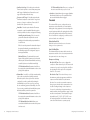
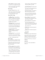
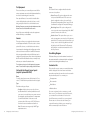
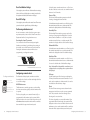
©2011 ecobee
333 Adelaide Street West | 6th Floor
Toronto | Ontario | M5V 1R5 | Canada
toll free 1.877.932.6233
www.ecobee.com
IM-STAT-203-R1
SMART Thermostat
Installation Manual
CONTENTS
Getting Started 2
Welcome2
Technical Support
2_
Before You Begin
3
HVAC System Compatibility Information
3
FCC Compliance Statement
4_
Specifications5
Installing the ecobee Smart Thermostat
Installing the Equipment Interface
Wiring the Equipment Interface
Wiring Diagrams
Installing the Smart Thermostat
Connecting the Smart Thermostat
to the Equipment Interface
Connecting Power
Equipment Interface Status LED
7
7
8_
9
15
16_
17
18
Navigating the Smart Thermostat
19
Configuring the Installer Settings
20
Configuring the Installer Settings
20_
Installation Wizard
20_
Equipment20
Thresholds24
Test Equipment
27
Sensors27
Setting up the Remote Sensor Inputs
27
View Wiring Diagram
28
Contractor Info
28
Reset Installation Settings
29
Reset All Settings
29
Performing a Hardware Reset
29_
Configuring the Reminder Alerts
29
Alerts30
Warranty31
GETTING STARTED
Welcome
Thank you for supporting ecobee, the Smart Thermostat
that provides your customers with freedom and flexibility
in managing their home environment.
The ecobee Smart Thermostat has been designed
in partnership with HVAC contractors to ensure the
installation process is simple and efficient. This
step-by-step Installation Manual will walk you through
all aspects of the installation.
To ensure an on-going service relationship with your
customers, please register all of your ecobee Smart
Thermostats in your Contractor Portal.
The ecobee Team
Technical support
Our technical support team is available to answer your
questions at 1.877-9-ecobee (1.877.932.6233), or via
email at [email protected].
2
1.
ecobee
Before You Begin
Equipment Description This product is intended to be installed by trained
service professionals
Gas/Oil/Electric heating (up to three stages)
Yes
Heat pump with auxiliary heat (up to four stages)
Yes
This manual explains the procedures for installing the
ecobee Smart Thermostat. Please read it carefully before
beginning the installation.
Geothermal Heat Pump
Yes
Duel fuel systems
Yes
For information on how to operate the ecobee Smart
Thermostat, please see the ecobee User’s Manual.
Standard electric cooling (up to two stages)
Yes
The ecobee Smart Thermostat consists of two parts
(see images below):
Central humidifier
Yes
Central dehumidifier
Yes
1. A Smart Thermostat to be mounted on the
homeowner’s wall.
Heat Recovery Ventilator (HRV)
Yes
Energy Recovery Ventilator (ERV)
Yes
2. An Equipment Interface Module This should be
mounted in the homeowner’s utility room and
connects to the heating, cooling and ventilation
equipment.
Sensors with dry contact outputs
Yes
Caution: Disconnect electric power to the system before
installing this product. Failure to do so could result in
electric shock and/or equipment damage.
All wiring must conform to your local electrical code.
Mercury Notice: This product does not contain mercury.
If you are replacing a product that does contain
mercury please contact your local waste-management
authority for disposal instructions. Do not discard the
old product in the regular trash.
2.
HVAC System Compatibility information
ecobee is designed to operate low-voltage heating and
cooling systems. It is not designed for use with linevoltage or millivolt heating and cooling systems. ecobee
supports control of up to four heating stages and two
cooling stages. It also supports control of humidifiers,
dehumidifiers, heat-recovery ventilators and
energy-recovery ventilators.
3
Getting Started
BoilersYes
Approvals
This product was designed and built in accordance to
RoHS directive 2002/95/EC and contains no hazardous
substances as defined by this directive.
Optional Power supply meets EPA C.E.C Level IV and E.C
CoC No Load power Consumption requirements. It is
also safety approved to UL/cUL standards.
FCC Compliance Statement
This equipment has been tested and found to comply
with the limits for Class B digital devices, pursuant
to Part 15 of the FCC Rules. These limits are designed
to provide reasonable protection against harmful
interference in a residential installation. This equipment
generates uses and can radiate radio frequency energy
and, if not installed and used in accordance with the
instruction manual, may cause harmful interference to
radio communications. However, there is no guarantee that
interference will not occur in a particular installation.
If this equipment does cause harmful interference to
radio or television reception, which can be determined
by turning the equipment off and on, the user is
encouraged to try to correct the interference by one or
more of the following measures:
Getting Started
4
Reorient or relocate the receiving antenna
Increase the separation between the equipment
and receiver
Connect the equipment to an outlet on a different
circuit from the receiver
Consult the dealer or an experienced radio/TV
contractor for help.
Warning: Changes or modifications not expressly
approved by ecobee Inc. could void the user’s
authority to operate the equipment.
To satisfy FCC/IC RF exposure safety requirements, a
separation distance of 20 cm or more should be maintained
between this device and persons. To ensure compliance,
operation at closer than this distance is not allowed.
FCC ID: WR9EBSTAT
IC: 7981A-EBSTAT
Specifications
Temperature ranges
Heat: 45 – 79°F (7 – 26°C)
Cool: 58 – 92°F (14 – 33°C)
Display: 40 – 100°F (5 – 37°C)
Sensitivity: +/- 1°F (0.5°C)
Equipment Interface Operating: -40o to 160oF (-40o to 70oC)
Thermostat Operating: 32o to 130oF (0o to 55oC)
Humidity Range
Humidify: 20 to 50% R.H
Dehumidify: 30 to 60% R.H
Display: 0 - 90% R.H
Sensitivity: +/- 2% R.H.
Operating: 5 – 95% R.H non-condensing
Dimensions
Thermostat: 5.5”W x 3.25”H x 1”D (139.5mm H x 82.5mm
W x 25mm D)
Equipment Interface: 4.6”W x 10”H x 1.3”D (118mm W x
254mm H x 32mm D)
Power
AC Transformer - 24 VAC - 3VA Minimum (not included)
Battery – CR2032 – 3V lithium coin cell (included),
Power Adaptor - #EB-PS-01 - 120V 50/60Hz to 12V DC 1A
(not included)
5
Getting Started
Wiring Specifications
Refer to this table to determine maximum wire lengths allowed:
Smart Thermostat to Equipment Interface
18 AWG
20 AWG
22 AWG
1250ft/380m790ft/240m 500ft/150m
Equipment Interface to heating/air equipment
18 AWG
20 AWG
128ft/39m 80ft/24m
22 AWG
50ft/15m
Terminal Description and Electrical Ratings
Terminal
Description
Voltage
Current max
Y
1st stage cooling
30V AC
3A
W (O/B)
1st stage heating
(or changeover)
30V AC
3A
G
W2(AUX)
Fan
30V AC
3A
2nd stage heating
(or 1st auxiliary heat)
30V AC
3A
R/H
Heat transformer return
30V AC
3A
R/C
Cool transformer return
30V AC
3A
ACC1
1st accessory relay
30V AC
3A
ACC1r
1st accessory relay return
30V AC
3A
ACC2
2nd accessory relay
30V AC
3A
ACC2r
2nd accessory relay return
30V AC
3A
ACC3
3rd accessory relay
30V AC
3A
ACC3r
3rd accessory relay return
30V AC
3A
IN1 +
Input 1 +
Dry contact only
Dry contact only
IN1-
Input 1 -
Dry contact only
Dry contact only
IN2+
Input 2 + Dry contact only
Dry contact only
IN2-
Input 2-
Dry contact only
Dry contact only
+12v
12V DC power to Thermostat
8-14V DC
600mA
GND
GND to Thermostat
-
-
D+
Data + communication line
-
-
D-
Data – communication line
-
-
Getting Started
6
Installing the
Smart Thermostat
There are five steps to installing the ecobee Smart Thermostat
Step 1: Install the Equipment Interface.
Step 2: Wire the Equipment Interface.
Step 3: Install the Smart Thermostat.
Step 4: Connect the Smart Thermostat to the
Equipment Interface.
Step 5: Power up both devices.
Installing the Equipment Interface
To install the Equipment Interface:
1. In the homeowner’s utility room or basement, select
a suitable location either on a wall or on the cold air
return plenum. Make sure the surface is relatively flat
and, if you are using a power adaptor, make sure there is
an electrical outlet within five feet of where you plan to
mount the device.
2. Remove the front cover of the Equipment Interface. If
necessary, Insert a flat-head screwdriver into one of the
slots as shown below, and gently twist the screwdriver.
Mounting holes indicated with solid color
4. Move the back of the enclosure out of the way and
make the holes where indicated in step 3. The mounting
holes can accommodate a #6 pan-head screw.
5. Use drywall plugs or other screw anchors (not
included) to ensure the Equipment Interface can be
mounted securely.
6. Fasten the backplate to the wall using the appropriate
screws (not included).
Wiring the Equipment Interface
To wire the Equipment Interface:
1. Disconnect the power to the heating and air
conditioning equipment.
2. Disconnect the wires going to the existing Thermostat.
Insert a screwdriver into one of the two slots and twist gently
3. Place the back of the enclosure on the intended
mounting surface and use it as a template to mark the
location of the mounting holes, as shown below.
7
Installing The Smart Thermostat
3. Using the wiring diagrams on pages 9-14, connect
the heating or air conditioning equipment to the
Equipment Interface.
4. Do not apply power until you have installed and
connected the Smart Thermostat. (see instructions on
page 15-18)
5. Do not install the front cover on the Equipment
Interface at this point.
Installing The Smart Thermostat
8
Wiring Diagrams
Below are the Equipment Interface Terminal Labels
Please take note that there is a factory installed jumper
between R/H and R/C.
24 Vac
Two Stage Heat/ Single Stage Cool With 3 Accessories
Power
Equipment Interface
System
Line
Communications
Y
W O/B
G
W2 AUX
R/H
Y
W O/B
G
W2 AUX
R/H
R/C
NC
NC
ACC1
ACC1r
IN2IN2+
R/C
HRV
ACC2
ACC2r
ACC3
ACC3r
IN1IN1+
D-
Dehumidifier
Humidifier
D+
Furnace
Air Conditioner
Y1
W1
G
W2
R
Y2
Hum
C
24V
C
Humidifier
24V
C
HRV
ACC1
ACC1r
24V
C
ACC2
ACC2r
ACC3
ACC3r
Dehumidifier
24V
C
GND
+12V
Single Stage Heat/Cool With 3 Accessories
Two Stage Heat/Cool With 2 Accessories
Dual Stage Heat, Single Stage Cool with Three Accessories
NOTE Non Powered Accessories will require a jumper from RH | RC to ACC1, ACC2, ACC3 for a 24V feed.
factory installed jumper.
Equipment Interface
Y
W O/B
G
W2 AUX
R/H
R/C
HRV
Dehumidifier
Humidifier
Furnace
Y
W
G
R
Hum
C
Diagram indicates 24V humidifier terminal. If your furnace control board does not have this, you must use a 110V/24V step down transformer.
Equipment Interface
Furnace
Air Conditioner
24V
24V
Y
W O/B
G
W2 AUX
R/H
C
R/C
C
Humidifier
HRV
ACC1
ACC1r
HRV
24V
C
ACC2
ACC2r
ACC3
ACC3r
Comp2
Dehumidifier
24V
Humidifier
Air Conditioner
Y1
Y2
R
C
Y1
W1
G
W2
R
Y2
Hum
C
Humidifier
24V
C
ACC1
ACC1r
HRV
ACC2
ACC2r
ACC3
ACC3r
24V
C
C
Single Stage Heat/Cool with Thrre Accessories
NOTE
factory installed jumper.
Non Powered Accessories will require a jumper from RH | RC to ACC1, ACC2, ACC3 for a 24V feed.
Diagram indicates 24V humidifier terminal. If your furnace control board does not have this, you must use a 110V/24V step down transformer.
9
Installing The Smart Thermostat
Dual Stage Heat/Cool with Two Accessories
NOTE
Indicates jumper. Non Powered Accessories will require a jumper from RH | RC to ACC1, ACC2, ACC3 for a 24V feed.
factory installed jumper.
indicates a jumper. Non-powered accessories require a jumper
from RH / RC to ACC1, ACC2, ACC3 for a 24V feed.
Diagram indicates 24V humidifier terminal. If your furnace control board does not have this, you must use a 110V/24V step down transformer.
Installing The Smart Thermostat
10
Three Stage Heat 2 Stage Cool With 1 Accessories
Equipment Interface
Furnace
Y1
W1
G
W2
R
Y2
W3
Hum
C
Y
W O/B
G
W2 AUX
R/H
R/C
3rd Stage
Heat
2nd Stage
Cool
Humidifier
ACC1
ACC1r
Two Stage Heat/Cool With 1 Stage Auxiliary Heat (Duel Fuel) with 2 Accessories
Equipment Interface
Air Conditioner
Y1
Y2
R
C
Y
W O/B
G
W2 AUX
R/H
Humidifier
R/C
ACC2
ACC2r
ACC3
ACC3r
Comp2
Humidifier
O
W2
W1
Y/Y2
G
R
C
R/C
Aux Heat
Stage 2
Humidifier
NOTE
O
W2
Y
R
C
Y
W O/B
G
W2 AUX
R/H
R/C
Humidifier
Comp2
Humidifier
C
11
Installing The Smart Thermostat
24V
C
Y1
W1
G
W2
R
Y2
Hum
C
Heat Pump
O
Y1
W2
Y2
R
C
Humidifier
24V
ACC1
ACC1r
C
ACC2
ACC2r
ACC3
ACC3r
Dual Stage Heat/Cool, Dual Stage Auxiliary Heat with One Accessory
NOTE
Single Stage Heat/Cool , Dual Stage Auxiliary Heat with Humidifer
Indicates jumper. Non Powered Accessories will require a jumper from RH | RC to ACC1, ACC2, ACC3 for a 24V feed.
factory installed jumper.
HRV
Diagram indicates 24V humidifier terminal. If your furnace control board does not have this, you must use a 110V/24V step down transformer.
Equipment Interface
Furnace
C 110V
CONFIGURE ACC2 - Emerg Heat 2 | ACC3 - Humidifier
C
ACC2
ACC2r
ACC3
ACC3r
Dual Stage Heat/Cool, Single Stage Auxiliary Heat with Two Accessories
1-Speed Heat Pump
24V
24V
Indicates jumper. Non Powered Accessories will require a jumper from RH | RC to ACC1, ACC2, ACC3 for a 24V feed.
factory installed jumper.
Aux Heat
Stage 2
C
24V
Y2
R
C
Two Stage Heat/Cool Two Stage Auxiliary Heat (Duel Fuel) With One Accessory
NOTE
ACC1
ACC1r
ACC2
ACC2r
ACC3
ACC3r
O
Y1
W2
ACC1
ACC1r
Three Stage Heat, Two Stage Cool with One Accessory
Indicates jumper. Non Powered Accessories will require a jumper from RH | RC to ACC1, ACC2, ACC3 for a 24V feed.
factory installed jumper.
Y
W O/B
G
W2 AUX
R/H
Y
W
G
R
Hum
C
Humidifier
C
HRV
Diagram indicates 24V humidifier terminal. If your furnace control board does not have this, you must use a 110V/24V step down transformer.
Equipment Interface
Fan Coil
Heat Pump
24V
1 Stage Heat/Cool With 2 Stage Auxiliary Heat (Duel Fuel) With Humidifier Accessory
NOTE
Furnace
Indicates jumper. Non Powered Accessories will require a jumper from RH | RC to ACC1, ACC2, ACC3 for a 24V feed.
factory installed jumper.
indicates a jumper. Non-powered accessories require a jumper
from RH / RC to ACC1, ACC2, ACC3 for a 24V feed.
Diagram indicates 24V humidifier terminal. If your furnace control board does not have this, you must use a 110V/24V step down transformer.
Installing The Smart Thermostat
12
Two Stage Furnace (Carrier 58MVB) With Two Stage Heat Pump (Duel Fuel)
Equipment Interface
Furnace
W2
Y1
W/W2
Y/Y2
G
R
Y
W O/B
G
W2 AUX
R/H
R/C
Aux Heat
Stage 2
Comp2
Dehumidifier
Heat Pump
O
Y1
W2
Y2
R
C
Dhum
Com
Hum
ACC1
ACC1r
Humidifier
24V
C
ACC2
ACC2r
ACC3
ACC3r
Humidastat
Dual Transformer – Dual Stage Cooling With Boiler
Dual Transformer – Single Stage Cooling With Boiler
Dual Stage Furnace with Dehumidifier and Two Stage Heat Pump
NOTE
Indicates jumper. Non Powered Accessories will require a jumper from RH | RC to ACC1, ACC2, ACC3 for a 24V feed.
factory installed jumper.
Equipment Interface
Diagram indicates 24V humidifier terminal. If your furnace control board does not have this, you must use a 110V/24V step down transformer.
Equipment Interface
Y
W O/B
G
W2 AUX
R/H
Fan Coil
Y
G
R
C
R/C
Fan Coil
Air Conditioner
Air Conditioner
Boiler
R
C
W
Y1
Y2
G
R
C
Y
W O/B
G
W2 AUX
R/H
24V
C
Comp 2
R
C
Boiler
R/C
ACC1
ACC1r
Y1
Y2
R
C
ACC1
ACC1r
W
ACC2
ACC2r
ACC3
ACC3r
ACC2
ACC2r
ACC3
ACC3r
Dual Stage Cooling with Boiler
Single Stage Cooling with Boiler
NOTE
NOTE
Remove factory installed jumper
13
Installing The Smart Thermostat
factory installed jumper must be removed for this configuration.
Non Powered Accessories will require a jumper from RH | RC to ACC1, ACC2, ACC3 for a 24V feed.
factory installed jumper must be removed for this configuration.
Non Powered Accessories will require a jumper from RH | RC to ACC1, ACC2, ACC3 for a 24V feed.
indicates a jumper. Non-powered accessories require a jumper
from RH / RC to ACC1, ACC2, ACC3 for a 24V feed.
Installing The Smart Thermostat
14
Installing the Smart Thermostat
The ideal location for the Smart Thermostat is
approximately five feet (1.5m) above floor level in the
main living area.
Do not install the Smart Thermostat:
Close to sources of heat such as incandescent lights
or heating/cooling registers.
In direct sunlight.
On exterior, non-insulated or poorly insulated walls.
In the kitchen or other areas of potentially high heat
and/or humidity.
In an area that could restrict air flow.
To Install the Smart Thermostat:
1. Remove the front cover of the Smart Thermostat,
insert a flat-head screwdriver into one of the slots as
shown below and gently twist the screwdriver.
4. Move the backplate out of the way and make holes
where indicated in step 3. The mounting holes can
accommodate a #6 pan-head screw.
5. Use drywall plugs or other screw anchors (not
included) to ensure the Smart Thermostat can be
mounted securely to the wall.
6. Fasten the backplate to the wall using the appropriate
screws (not included).
Connecting the Smart Thermostat to
the Equipment Interface
Only four wires are needed to connect the Smart
Thermostat to the Equipment Interface. If you are
replacing a Thermostat, you can use the existing wiring.
Note: Ensure any unused wires do not have exposed
bare copper conductors.
Follow these steps to connect the Smart Thermostat to the
Equipment Interface:
1. Connect the wires between the Smart Thermostat and
Equipment Interface as shown below.
DD+
GND
Equipment
Interface
+12V
D-
Insert screwdriver into one of the two slots and twist gently
2. Place the Smart Thermostat backplate on the wall.
Make sure that any existing wires can be inserted
through the opening for the wiring.
3. Using the backplate as a template, mark the location
of the mounting holes on the wall as shown below.
D-
Installing The Smart Thermostat
Thermostat
Wiring from Smart Thermostat to the Equipment Interface
2. Attach the front cover of the Smart Thermostat to the
backplate. Ensure the four pins on the circuit board mate
with the terminal block on the backplate as shown below.
D+ GND +12V
The solid color indicates mounting holes
15
D+ GND +12V
Replace the front cover ensuring the pins meet the terminals
Installing The Smart Thermostat
16
Equipment Interface Status LED
+
Note the small clips
on the edge of the
battery encasing.
The Equipment Interface has four LEDs to display the
status of the system.
Slide the battery under the contacts and push down firmly
Push down on the
battery firmly until
it snaps into place.
Slide the battery
UNDER the clips.
If you’ve wired the system correctly, only the Power LED
should be on.
The Thermostat comes with a factory installed, coin cell
battery. When replacing the battery ensure the + side of
the battery is facing out and the battery contacts remain
in the upright position (not bent underneath the battery).
The battery should snap in easily.
Power
System
Line
Communication
Connecting Power
LED arrangement
Once you’ve completed the wiring of the Smart
Thermostat and Equipment Interface, you can apply
power to the Equipment Interface and restore power
to the heating and air conditioning equipment.
There are two methods of powering the Smart
Thermostat. You can power it directly from a 24VAC
source capable of at least 3VA.
24 Vac
The LEDs operate as follows:
Power This LED monitors the power supply of the
Equipment Interface.
LED ON
Power is connected to the Equipment
Interface and is within the appropriate
voltage range.
LED OFF
Power is disconnected or has dropped
below 9V.
System This LED monitors the operation of the
Equipment Interface.
24Vac | 3VA min
Hard-wired 24 VAC option
The second method requires the optional 120V to 12Vdc
power adaptor. Plug the power supply into a standard
electrical outlet and plug the barrel connector into the
Equipment Interface.
LED ON
There is a fault with the Equipment Interface.
LED OFF
The equipment interface is operational.
Line This LED monitors the power supplied to the Smart
Thermostat from the Equipment Interface.
LED ON
The voltage at the +12V and GND terminal
has dropped below 7V.
LED OFF
Adequate power is being supplied to the
Smart Thermostat.
Communication This LED monitors the communication
Plug the adaptor into the Equipment Interface
17
Installing The Smart Thermostat
between the Smart Thermostat and the Equipment
Interface (i.e., the D+ and D- terminals).
LED ON
The Equipment Interface and Smart Thermostat
are not communicating with each other.
LED OFF The two devices are communicating properly.
Installing The Smart Thermostat
18
Navigating the
Smart Thermostat
Configuring the
Smart Thermostat
Once the Smart Thermostat and Equipment Interface
are powered up and working correctly, you can begin
configuring the system.
Configuring the Installer Settings
The Smart Thermostat uses touch screen technology, so it’s
easy to navigate – just tap the icons, buttons and lists.
Note: To prevent damage to the touch screen, never use a sharp
object such as a pen.
When the screen shows a list setting an arrow on the right,
it indicates there are more than two options to choose from.
If there is no arrow, then the list item only has two options.
Toggle between options by pressing the list item.
In the various screens, you have three navigation choices:
Press Done to save changes and move to the next screen.
Press Cancel to go back to the previous screen without
saving changes.
At any time, press the Home button (found on the
right-hand side of the touch screen). This cancels any
action and takes you back to the home screen.
If you need to enter data in the form of text, you will be
presented with a keyboard.
Pressing the Caps key will allow you to enter capital
letters; pressing the 123@ key will change the letters to
numbers or commonly used symbols.
Installer Settings let you configure the settings related
to the various devices (such as a furnace, air conditioner,
humidifier, dehumidifier or ventilator) that are connected
to the Equipment Interface.
To prevent accidental modifications to these settings
you can enable a 4-digit installer code. This code is
pre-programmed to 3262 and can be enabled in the
Thresholds option menu.
To configure the installer
settings:
From the Home
screen, press More.
Press Settings and
select Installation
Settings
Installation Wizard
The Installation Wizard takes you step-by-step through
a series of choices regarding the HVAC equipment
intended to be connected to the Equipment Interface.
Simply answer the questions accordingly and press Next
to advance to the next screen. Once completed you
will be shown a diagram of the wiring connections that
reflects the choices made during the wizard process. You
can press Back to go back and make any changes. Once
you are satisfied with the setup, press Done.
Equipment
The equipment setting will allow you to manually
configure the various devices that are connected to
the Equipment Interface.
Heat Pump
This section allows you to enable and configure up to
a 2 stage heat pump. If a second stage is required you
must configure an Accessory relay to control that stage
Geothermal/Ground Source Heat pump If you select
Yes, this tells the system a geothermal or ground source
heat pump is being controlled. This helps the Thermostat
determine optimum performance and default settings.
If you select NO, the system will optimize for an air-to-air
heat pump.
O/B Energize on Cool If you choose Yes, the reversing
valve output (O/B terminal) will activate when there is a
call for cooling. If you select No, the relay will energize
when there is call for heat.
19
Navigating The Smart Thermostat
Configuring The Smart Thermostat
20
Min Cycle Off Time Enables you to configure the
compressor off time between cycles. This is adjustable
from 240 - 900 Seconds.
Heat Stages Allows you to configure up to 3 stages of
heat. If you require a third stage, you must configure
an accessory relay to control that stage.
Min Outdoor Temp Allows you to set the minimum
outside air temperature at which the compressor will
be disabled. This performs two functions: You can set
it to prevent the compressor from going on when
the outdoor temperature is too low, thus resulting in
damage to the compressor. You can also set this value to
determine when you want the auxiliary heat (if installed)
to engage to help meet the set temperature. The
temperature range is adjustable from 0°F (-17.8°C) - 65°F
(18.3°C) or can be completely disabled. You will need an
internet connection for this feature to operate properly.
Heat Fan Control This option allows you to determine
if the system fan is controlled by the system during
heat cycles, or if the Thermostat is required to control
the fan. Normally the HVAC system controls the fan
during heat cycles.
Allow Heat Pump/Auxiliary Heat to Run Simultaneously
If you select Yes and there is a source of auxiliary
heat, it will turn on in addition to the heat pump. The
heat pump will be energized for the first 30 minutes.
If, after 30 minutes, the set point has not been met,
the auxiliary heat will be energized to assist the heat
pump in meeting the load.
If you select no, the heat pump will be energized for up
to 2 hours. If after 2 hours the set point has not been
met, the Thermostat will shutdown the heat pump and
energize the auxiliary heat to meet the set point. This
option should also be used for installation where the
heat pump evaporator coil is downstream from the
source of auxiliary heat.
Furnace (Auxiliary Heat)
Allows you to enable and configure up to a 3-stage
conventional heat source. If you have selected Heat
pump as your primary source, this feature will allow you
to configure the auxiliary heat connected to the system.
Furnace Type Allows you to configure the type of furnace connected. This allows the Smart Thermostat to
optimize its algorithms based on the type of fuel and
typical characteristics of the chosen system. Choose
the option that best represents the type of heating
system installed.
Air Conditioner
Allows you to enable and configure up to 2 stages of air
conditioning. If you require a second stage, you must
configure an accessory relay to control that stage.
Staging Method of Operation
The ecobee Smart Thermostat uses a unique method
for staging for multi-stage heating or cooling. It uses
a combination of intelligent algorithms and past
performance to determine when to activate the stages.
When there is a call for heat or cool, the system computes
how long it would take for the system to reach the desired
set point in stage 1, stage 2 or stage 3 accordingly. It will
determine the highest stage at which a minimum of 10
minutes of run time is required. It will then automatically
start the system at that stage (ie if it calculates that it will
take 15 minutes at stage 2 but only 7 minutes at stage 3,
the system will immediately turn on stage 2 to meet the
set point). If the calculation indicates to start at stage 1,
and it takes more than 10 minutes to reach the set point,
it will automatically engage stage 2. If stage 2 runs for
more than 10 minute without reaching the set point it will
activate stage 3. A minimum run time of 10 minutes is used
to ensure that proper circulation throughout the system
and that minimum cycle times are maintained. For heat
pumps with auxiliary heat, the operation of the auxiliary
heat will depend on the configuration of the Allow Heat
Pump/Auxiliary Heat to Run Simultaneously.
Accessory relays
Accessory relays are generic relays that can be configured
to control the following;
21
Configuring The Smart Thermostat
Heat Stage 3 Select this option when the Thermostat
is required to control a 3-stage conventional heating
system. Connect the third stage (or W3) contact to this
accessory relay.
Configuring The Smart Thermostat
22
Auxiliary Heat Stage 2 Select this option when the
Thermostat is required to control a heat pump system
with 2 stages of Auxiliary heat. Connect the second
stage of the auxiliary heat to this relay.
Compressor/AC Stage 2 Select this option when the
Thermostat is required to control either a 2 stage heat
pump or a 2 stage air conditioner. Connect the Y2
terminal of the system to this relay.
Humidifier Select this option when the Thermostat
is required to control a humidifier. When this option is
selected you will also be able to configure the following:
Humidify only while heating If Yes is chosen, the
system will activate this relay when the current
humidity is below the humidity set point and there
is a call for heat.
If No is chosen the system will activate this relay and
the system fan when the current humidity is below
the humidity set point. This is designed to support
steam type humidifiers
Window Efficiency To optimize the frost control
feature of this system the system needs to know the
efficiency ratio of the windows within the area being
controlled. Options are Low, Medium and High.
NEW Min Runtime Delta Determines how far from
the set point, the system will maintain to reduce short
cycling of the equipment.
Dehumidifier On a call for cool, if the current humidity
is above the set point, this relay will be activated.
When this option is selected you will also be able to
configure if you wish to enable the fan during the
dehumidification cycle. Choose yes if you are using
the air conditioning system to dehumidify, choose No
if you are using a standalone dehumidification system
that independently controls the system fan.
NEW Min Runtime Delta Determines how far from
the set point, the system will maintain to reduce short
cycling of the equipment.
NEW Dehumidify in Heat Mode Allows you to
control the dehumidification even when the system
is in heat mode.
23
Configuring The Smart Thermostat
NEW Dehumidifier Active Allow you to configure if
the active stat of this relay is open or closed.
Ventilator Activated when the user engages Ventilator
Max from the Details screen. The system fan will also
turn on when Ventilator Max is engaged
Thresholds
This section will allow you to configure the various
temperature or time thresholds associated with the
heating and cooling equipment. You must configure the
required equipment first before setting the thresholds,
and only the application thresholds will be shown (i.e.
if no air conditioner is configured, you will not see the
options related to air conditioners).
Allow Auto Heat/Cool
Enable this option to allow the user to select auto
change-over as a system mode.
Heat/Cool Min Delta
The minimum difference between the heat mode set
temperature and the cool mode set temperature when
the system mode is in auto change-over.
Compressor Settings
Min Cycle Off Time Allows you to configure the
compressor off time between cycles. This ensures the
compressor does not short cycle which could affect
the operating life of the system. This is adjustable
from 240 - 900 seconds.
Min Outdoor Temp This section allows you to set
the minimum outside air temperature at which the
compressor will be disabled. This performs two
functions: You can set it to prevent the compressor
from going on when the outdoor temperature is too
low, thus resulting in damage to the compressor.
You can also set this value to determine when you
want the auxiliary heat (if installed) to engage to help
meet the set temperature. The temperature range is
adjustable from 0°F (-17.8°C) - 65°F (18.3°C) or can
be completely disabled. You will need an internet
connection for this feature to operate properly.
Configuring The Smart Thermostat
24
AC Overcool Max When using the AC to dehumidify,
the section allows you to program how many degrees
below the current set point the Thermostat will run in
order to reach the dehumidify set point.
Aux Heat Settings
Max Outdoor Temperature Allows you to set the
maximum outdoor temperature threshold. Above this
level, the auxiliary heat will not be activated. Instead,
the heat pump will maintain the set point.
Common Heat/Cool Settings
Heat Differential Temp The minimum difference
between the current temperature and set temperature
before the system calls for heat. A smaller difference
means a more comfortable environment, whereas a
larger difference is more economical.
Heat Dissipation Time The amount of time the fan
will run after the heat set point has been reached and
the call for heat has been turned off. Running the fan
for a period of time allows for any heated air left in the
ducts to circulate throughout the home.
Cool Differential Temp The minimum difference
between the current temperature and the set
temperature.
Cool Dissipation Time The amount of time the fan
will run after the cool has been turned off. Running
the fan for a period of time allows for any cooled air left
in the ducts to circulate throughout the home.
Advanced Settings
This section will allow you to customize how long each
stage will run before the next stage will turn on. You may
also program when a particular stage is turned on based
on the temperature delta between the set temperature
and the current temperature.
temperature delta, stage 2 will disengage and stage 1
remain running until the set point is meet.
Stage X Maximum Runtime The maximum amount of
time X stage will run before engaging the next stage.
Options are Auto and 10-120 minutes
Stage X Temperature Delta The minimum difference
between the current temperature and the set
temperature that will activate this stage (regardless
if the maximum run time of the previous stage was
reached). Options are Auto and 1-10F.
Comp to Aux Runtime The maximum amount of
time this stage will run before engaging the next stage.
Options are Auto and 10-180 minutes
Comp to Aux Temp Delta The minimum difference
between the current temperature and the set
temperature that will activate this stage (regardless if the
maximum run time of the previous stage was reached).
Options are Auto and 1-10F.
Cool Min On Time Sets the minimum equipment run
time in cool mode.
Heat Min On Time Sets the minimum equipment run
time in heat mode.
Temp Correction
This will allow you to program an offset between what
temperature the Thermostat is measuring versus what
is displayed. If you find that the temperature where
the Thermostat is located does not represent the room
temperature, this offset allows you to compensate for
that difference.
Installer Code
This option lets you enable or disable 3262 as the
installer code.
NEW Reverse staging If this option is enabled, the
thermostat will cycle down from the higher stages so
that as it approaches set point it will only be running
in stage 1. The HVAC equipment will start in stage
1. As the stage 1 temperature delta is exceeded, the
second stage will engage. Once the equipment has
brought the current temperature back to within the
25
Configuring The Smart Thermostat
Configuring The Smart Thermostat
26
Test Equipment
This section allows you to manually turn on and off the
various equipment connected to the Equipment Interface,
in order to test the wiring and connections.
If an optional Remote Sensor module is installed this
section will display the actual value (in ohms or volts)
being read by the module for each individual sensor.
Warning: Compressor protection and minimum run-time
features are not enforced while in this mode.
In any of the screens within this section, the equipment
will turn off when you select Done.
Sensors
This section allows you to configure the detector inputs
on the Equipment Interface. This can be used to connect
optional flood sensors, or other leak-detection devices.
Once an input has been triggered, it will generate an alert
on the touch screen and send an e-mail if the Thermostat
has been registered with a web portal. Each input can be
configured as normally open, where a short-circuit between
the IN1+ and IN1 will activate the alert, or normally closed,
where an open circuit will activate the alert.
To activate any input, select the input and program a
name. To deactivate the input, simply delete the name.
Setting Up the Remote Sensor Inputs
(requires optional EB-RSM)
Name
To enable, simply enter a name for this input (i.e. Door
sensor). To disable this input delete the name assigned.
Type
This defines the type of input.
Configure In this section you can choose from a
predetermined list of commonly available sensors. If
your sensor is not on the list you can create a new one
by entering the specific parameters. For temperature
you will need the B value of the sensor or the
resistance value of the sensor at 70F (21C) these are
found on the sensor manufacturers data sheet.
Note: The remote sensor support only 10K NTC type
temperature sensors.
27
Configuring The Smart Thermostat
Usage
This section allows to configure what function this
sensor needs to perform
Control Sensor This option configures the sensor
to be part of the HVAC control. These sensor can
then be configured to replace or be part of a the
Thermostat Set temperature. Refer to page 27 in the
User Manual to configure Set Temperature Average.
Monitoring Sensor This option configures the
sensor to monitor areas independently of the HVAC
system (ie freezers, wine cellars etc).
Outdoor Sensor This options allows you to use a
outdoor temperature sensor in place of the internet
weather feed. The value measured here will be used
for any control or dual fuel algorthiims and it will
be displayed on the Thermostat. The Thermostat
will coniintuie t use the internet weather feed for
the 5-day forecast
View Wiring Diagram
This feature allows you to view the terminal connections of
the equipment interface as determined by the configuration
options selected during the installation process.
Contractor Info
This section allows you to enter your contact information.
It will be displayed to the homeowner in the About
menu, when any alert is shown on the touch screen and in
his personal web portal. You can enter your:
Company name
Phone number
Email address
Website address.
If you are a registered ecobee contractor, you will
have access to your Contractor portal. In this portal,
you can enter the serial number of each ecobee
Smart Thermostat you install. Once your registered
Thermostats are connected to the Internet, your
contact information, including your company logo,
will be automatically loaded onto them.
Configuring The Smart Thermostat
28
Reset Installation Settings
Selecting this option will restore all the installation settings
back to the factory default. Any user setting (not related to
the equipment installed) will remain unchanged.
Reset All Setting
Selecting this option will reset the entire Smart Thermostat
system back to the original factory default settings.
Performing a Hardware reset
In rare circumstances, static electricity or power surges
may interrupt the operation of the Smart Thermostat or
Equipment Interface, forcing a hardware reset.
Resetting the Smart Thermostat
You can reset the Smart Thermostat by pressing the
hardware reset button, located through an opening in
the top left corner of the Thermostat, as shown below.
Pressing the hardware reset button will not alter
programming or configuration options.
Select this item to turn the reminder on or off, to show
the date of the last service and to set a reminder interval
between 1 and 12 months.
Furnace Filter
The Furnace Air Filter reminder generates an alert for
cleaning or changing the furnace air filter.
Select this item to turn the reminder on or off, and to select
the reminder interval (in hours or calendar months). This
reminder also displays the date of the last filter change.
Humidity Filter
The Humidity Filter reminder generates an alert for
cleaning or changing the humidity filter. Select this
item to turn the reminder on or off, and to select the
reminder interval (in hours or calendar months). This
reminder also displays the date of the last filter change.
Dehumidifier Filter
Select this item to turn the reminder on or off, and to select
the reminder interval (in hours or calendar months). This
reminder also displays the date of the last filter change.
Ventilator Filter
Select this item to turn the reminder on or off to choose
the reminder interval in run-time hours or calendar months.
You can also check the date of the last filter change.
Reset button indicated in solid colour
To configure reminder alerts:
From the Home
Screen, press More.
Press Settings and
select Reminders and
Alerts from the list.
Configuring reminder alerts
UV Lamp
The Reminders list displays the reminders and alerts
described below. Use the scroll bar at the right of the list
to see all the settings.
Sets the reminder period for cleaning or replacing the
UV lamp. Select this item to turn the reminder on or off
and to set the reminder in calendar months. You can also
check the date of the last lamp change.
HVAC Maintenance
The Maintenance reminder generates an alert telling
the homeowner that regularly scheduled maintenance
is required.
This alert, along with your contact information (if you
programmed the information into the system), will be
displayed on the touch screen. If the homeowner enrolls
with www.ecobee.com, this reminder will be emailed to
them and will also appear in their web portal.
29
Note: If a humidifier, dehumidifier or ventilator is not
configured in Accessory Relays, these options will not
be displayed.
Configuring The Smart Thermostat
Alerts
The Smart Thermostat can generate alerts when the
temperature in the home reaches a pre-programmed
level. This protects the home from damage due to
freezing and/or excessive heat.
This alert, along with your contact information (if you
programmed the information into the system) will be
displayed on the touch screen. If the homeowner enrolls
with www.ecobee.com, this reminder will be e-mailed to
them and will also appear in their personal web portal.
Configuring The Smart Thermostat
30
Below is a complete list of alerts. Depending on your
configuration, some of these may not apply to your system.
Low Battery
High Temperature Alert Select this to set the
temperature at which the Smart Thermostat will generate
a High Temperature Alert. The range can be:
The battery in your Thermostat will need
to be changed soon.
Furnace Air Filter
Your furnace filter needs to be
cleaned/changed.
Ventilator Filter
Your ventilator filter needs to be
cleaned/changed.
UV Lamp
Your UV lamp needs to be changed.
Humidifier Filter
Your humidifier pad needs to be
cleaned/changed.
Comms fault
There is no communication between the
Thermostat and the Equipment Interface
module.
Low Temp. Alert
The temperature in the home is too low.
High Temp Alert
The temperature in the home is too high.
Low Humidity Alert
The humidity in the home is too low.
High Humidity Alert
The Humidity in the home is too high.
Heat Not
Responding
The system has failed to heat the home.
Cool Not
Responding
The system has failed to cool the home.
Input 1
Used if this input is programmed to
generate an alert.
Input 2
Used if this input is programmed to
generate an alert.
Maintenance
Reminder
You are due for regular maintenance.
Auxiliary Heat
Run Time
Your auxiliary heat source is running
too often.
Auxiliary Outdoor
Temperature
Your auxiliary heat source is running
at higher than expected outdoor
temperatures.
Off – no alert will be generated
Set temperature range of 76 – 104°F (24.5 – 40°C).
Low Humidity Alert Select this item to set the humidity
level at which the Smart Thermostat will generate a Low
Humidity alert. The range can be adjusted to:
Off – no alert will be generated
Set humidity range of 5 – 95% R.H. in 5% increments
High Humidity Alert Select this item to set the humidity
level at which the Smart Thermostat will generate a High
Humidity alert. The range can be adjusted to:
Off – no alert will be generated
Set humidity range of 5-95% R.H. in 5% increments
Auxiliary Heat Run-time Alert (optional)
In a heat pump with auxiliary heat configuration, you
can program the Smart Thermostat to generate an alert
if the auxiliary heat runs for more than this programmed
amount of time during a 24-hour period.
Auxiliary Outdoor Temperature Alert (optional)
In a heat pump with auxiliary heat configuration, you can
program the Smart Thermostat to generate an alert if the
auxiliary heat is called for when the outdoor temperature
exceeds this programmed set point (this feature requires
an internet connection to function properly)
Enable Alerts to be displayed on console
Select No, if you do not want any of the alerts to be display
on the touch screen interface. Alerts will continue to be
displayed on the web portal and sent via email.
Enable Heating and Cooling Alerts
Select No, if you do not want the Thermostat to generate
the System Failed to Heat or Cool alerts. If disabled, these
alerts will not be shown on the Thermostat or web portal
and no emails will be sent.
31
List of Alerts
Low Temperature Alert Select this to set the
temperature at which the Smart Thermostat will
generate a Low Temperature Alert. The range can be:
Off – no alert will be generated
Set temperature range of 35 – 68°F (1.5 – 20°C).
Configuring The Smart Thermostat
Configuring The Smart Thermostat
32
3-Year Limited Warranty
ecobee warrants that for a period of three (3) years from
the date of purchase by the consumer (“Customer”),
the ecobee Smart Thermostat (excluding battery) (the
“Product”) shall be free of defects in materials and
workmanship under normal use and service. During
the warranty period, ecobee shall, at its option, repair or
replace any defective Products, at no charge for labour
or materials. Any replacement and/or repaired device are
warranted for the remainder of the original warranty or
ninety (90) days, whichever is longer.
If the product is defective, call Customer Service at
1-877-9-ecobee. ecobee will make the determination
whether a replacement product can be sent to you or
whether the product should be returned to the following
address: ecobee Customer Service, 333 Adelaide Street
West, 6th Fl., Toronto, ON M5V 1R5, Canada. In the event
of a failure of a Product, Customer may:
(a) if Customer did not purchase the Product directly from
ecobee, contact the third party contractor from whom
the Product was purchased to obtain an equivalent
replacement product, provided the contractor determines
that the returned Product is defective and Customer is
otherwise eligible to receive a replacement product;
(b) contact ecobee directly for service assistance at
1-877-9-ecobee and ecobee will make the determination
whether an advance equivalent replacement Product
can be sent to Customer with return shipping supplies (in
which case a hold shall be put on Customer’s credit card
for the value of the replacement Product until ecobee
has received the defective Product). Product should be
returned to the following address: ecobee Customer
Service, 333 Adelaide Street West, 6th Fl., Toronto, ON M5V
1R5, Canada. If the returned Product is found by ecobee to
be defective and Customer is otherwise eligible to receive
a replacement product, no amount shall be charged to
Customer’s credit card; or
(c) ship the defective Product directly to ecobee, in
which case Customer shall contact ecobee directly
at 1-877-9-ecobee, so ecobee can make the required
shipping arrangements. Upon receipt of the defective
Product, ecobee will ship an equivalent replacement
product to Customer, provided the returned Product
is found by ecobee to be defective and Customer is
otherwise eligible to receive a replacement product.
31Warranty
This warranty does not cover removal or reinstallation
costs and shall not apply if the damages were found to be
caused by something other than defects in materials or
workmanship, including without limitation, if the Product:
was operated/stored in abnormal use or maintenance
conditions;
is repaired, modified or altered, unless ecobee expressly
authorizes such repair, modification or alteration in writing;
was subject to abuse, neglect, electrical fault, improper
handling, accident or acts of nature;
was not installed by a licensed Heating Ventilating and Air
Conditioning (HVAC) contractor; or
was installed improperly.
ecobee’s sole responsibility shall be to repair or replace
the Product within the terms stated above. ECOBEE
SHALL NOT BE LIABLE FOR ANY LOSS OR DAMAGE OF
ANY KIND, INCLUDING ANY SPECIAL, INCIDENTAL OR
CONSEQUENTIAL DAMAGES RESULTING, DIRECTLY OR
INDIRECTLY, FROM ANY BREACH OF ANY WARRANTY,
EXPRESS OR IMPLIED, OR ANY OTHER FAILURE OF THIS
PRODUCT. Some US states and Canadian provinces
do not allow the exclusion or limitation of incidental
or consequential damages, so the above limitation or
exclusion may not apply to you.
ecobee’s responsibility for malfunctions and deffects
in materials and workmanship is limited to repair and
replacement as set forth in this warranty statement.
All express and implied warranties for the product,
including but not limited to any implied warranties and
conditions of merchantability and fitness for a particular
purpose, are limited to the three-year duration of this
limited warranty. No waaranties, whether express or
implied, will apply after the limited warranty period has
expired. Some US states and Canadian provinces do not
allow limitations on how long an implied warranty lasts,
so this limitation may not apply.
ecobee neither assumes responsibility for nor authorizes
any other person purporting to act on its behalf to modify
or to change this warranty, nor to assume for it any other
warranty or liability concerning this product.
This warranty gives you specific rights, and you may also
have other rights which vary from jurisdiction to jurisdiction.
If you have any questions regarding this warranty, please
write ecobee Customer Service, 333 Adelaide Street West, 6th
Floor, Toronto, Ontario M5V 1R5, Canada.
Warranty32
33Notes
Notes
34