1
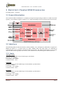
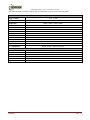
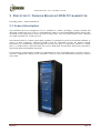
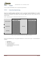
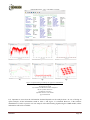
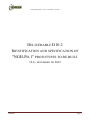
Deliverable D10.2 - V0.6 - December 14, 2012 DELIVERABLE D10.2 IDENTIFICATION AND SPECIFICATION OF "NGH-PH.1" PROTOTYPES TO BE BUILT V0.6 - DECEMBER 14, 2012 ENGINES Page 1 Deliverable D10.2 - V0.6 - December 14, 2012 Abstract This deliverable presents the different prototypes to be built within the TF10 of the ENGINES project for further evaluation of a ”NGH-Phase 1” transmission by TF11. After a definition of the target "NGH Phase 1" features, the document gives for each prototype, the type to be developed (either a software IP block or a complete hardware and software equipment), the interfaces with other prototypes in a DVB-T2 chain, and the preliminary DVB-NGH features supported by the prototype. ENGINES Page 2 Deliverable D10.2 - V0.6 - December 14, 2012 TABLE OF CONTENT 1 Introduction ................................................................................................................................................ 5 2 Definitions ................................................................................................................................................... 6 3 Prototype 1: TeamCast DVB-T2 modulator............................................................................................ 7 3.1 General description ............................................................................................................................... 7 3.2 Interfaces ............................................................................................................................................... 7 3.2.1 Inputs.............................................................................................................................................. 7 3.2.2 Outputs ........................................................................................................................................... 8 3.2.3 Control and monitoring .................................................................................................................. 8 3.3 Supported T2 modes and features ......................................................................................................... 8 4 Prototype 2 : Thomson Broadcast DVB-T2 modulator........................................................................ 10 4.1 General description ............................................................................................................................. 10 4.2 Interfaces ............................................................................................................................................. 10 4.2.1 Inputs............................................................................................................................................ 10 4.2.2 Outputs ......................................................................................................................................... 10 4.2.3 Control and monitoring ................................................................................................................ 10 4.3 Supported T2 modes and features ....................................................................................................... 10 5 Prototype 3 : Thomson Broadcast DVB-T2 transmitter ...................................................................... 12 5.1 General description ............................................................................................................................. 12 5.2 Interfaces ............................................................................................................................................. 13 5.2.1 General Specifications ................................................................................................................. 13 5.2.2 Inputs............................................................................................................................................ 13 5.2.3 Outputs ......................................................................................................................................... 13 5.3 Other general specifications ................................................................................................................ 13 5.3.1 Power Supply ............................................................................................................................... 13 5.3.2 Environmental Compliance.......................................................................................................... 14 6 Prototype 4: Mier DVB-T2 transmitter. ............................................................................................... 15 6.1 General description ............................................................................................................................. 15 6.2 Driver unit interfaces........................................................................................................................... 15 6.2.1 Inputs............................................................................................................................................ 15 6.2.2 Outputs ......................................................................................................................................... 16 6.2.3 Control interfaces. ........................................................................................................................ 16 6.3 Power unit interfaces........................................................................................................................... 16 6.3.1 Inputs............................................................................................................................................ 16 6.3.2 Outputs ......................................................................................................................................... 17 6.3.3 Control interfaces. ........................................................................................................................ 17 6.3.4 Control and monitoring. ............................................................................................................... 17 6.4 Supported T2 modes and features. ...................................................................................................... 17 7 Prototype 5: Mier DVB-T2 gapfiller. .................................................................................................... 18 7.1 General description. ............................................................................................................................ 18 7.2 Down-converter interfaces. ................................................................................................................. 18 7.2.1 Inputs............................................................................................................................................ 18 7.2.2 Outputs ......................................................................................................................................... 18 7.2.3 Control interfaces. ........................................................................................................................ 19 7.3 Up-converter interfaces. ...................................................................................................................... 19 7.3.1 Inputs............................................................................................................................................ 19 7.3.2 Outputs ......................................................................................................................................... 19 7.3.3 Control interfaces. ........................................................................................................................ 20 ENGINES Page 3 Deliverable D10.2 - V0.6 - December 14, 2012 7.3.4 Control and monitoring ................................................................................................................ 20 8 Prototype 6: LA SALLE DVB-T2 Gateway ......................................................................................... 21 8.1 General description ............................................................................................................................. 21 8.2 Features ............................................................................................................................................... 21 8.3 Supported modes ................................................................................................................................. 21 8.3.1 Single PLP – VV500 .................................................................................................................... 21 8.3.2 Multiple PLP – VV413 ................................................................................................................ 21 8.3.3 Multiple PLP – VV400 ................................................................................................................ 21 8.4 Interfaces ............................................................................................................................................. 22 8.4.1 Inputs............................................................................................................................................ 22 8.4.2 Outputs ......................................................................................................................................... 22 8.5 HW specifications ............................................................................................................................... 22 9 Prototype 7: MERCE SC-OFDM Evaluation Platform ....................................................................... 24 9.1 General description ............................................................................................................................. 24 9.1.1 HEP Central Unit ......................................................................................................................... 25 9.1.2 Transmitter (HEP Tx) .................................................................................................................. 27 9.1.3 Receiver (HEP Rx)....................................................................................................................... 29 9.2 Transmitter .......................................................................................................................................... 29 9.2.1 Inputs............................................................................................................................................ 29 9.2.2 Outputs ......................................................................................................................................... 29 9.2.3 Control interfaces ......................................................................................................................... 30 9.3 Receiver............................................................................................................................................... 30 9.3.1 Inputs............................................................................................................................................ 30 9.3.2 Control interfaces ......................................................................................................................... 30 9.4 Control interfaces ................................................................................................................................ 30 9.5 Features ............................................................................................................................................... 30 9.6 Supported modes ................................................................................................................................. 31 10 Prototype 8: Enensys DVB-T2 gateway ............................................................................................... 35 10.1 General description ........................................................................................................................... 35 10.2 Interfaces ........................................................................................................................................... 35 10.2.1 Inputs.......................................................................................................................................... 35 10.2.2 Outputs ....................................................................................................................................... 36 10.2.3 Control and monitoring .............................................................................................................. 36 10.3 Supported T2 modes and features ..................................................................................................... 36 11 Prototype 9: Enensys DVB-T2 modulator ........................................................................................... 38 11.1 General description ........................................................................................................................... 38 11.2 Interfaces ........................................................................................................................................... 38 11.2.1 Inputs.......................................................................................................................................... 38 11.2.2 Outputs ....................................................................................................................................... 38 11.2.3 Control and monitoring .............................................................................................................. 39 11.3 Supported T2 modes and features ..................................................................................................... 39 12 Prototype 10: UPV/EHU DVB-T2 demodulator ................................................................................. 40 12.1 General description ........................................................................................................................... 40 12.2 Interfaces ........................................................................................................................................... 41 12.2.1 Inputs.......................................................................................................................................... 41 12.2.2 Outputs ....................................................................................................................................... 42 12.2.3 Control and monitoring .............................................................................................................. 42 12.3 Supported T2 modes and features ..................................................................................................... 44 13 References ............................................................................................................................................... 45 ENGINES Page 4 Deliverable D10.2 - V0.6 - December 14, 2012 1 INTRODUCTION Within the WP4, TF10 deals with the prototyping of "Full T2" or "NGH phase 1" compliant equipment. This prototype equipment will be used for evalutation and validation of the corresponding advanced functional features/technologies. This evaluation / validation phase will rely on both laboratory tests and field tests respectively led within TF11 and TF12. Prototyping here means either hardware or software implementation. The developpement work within TF10 is led in two phases: • Phase 1: prototype implementation of "Full T2" compliant equipment, • Phase 2: prototype implementation of "NGH Phase 1" compliant equipment. This deliverable D10.2 reports about the phase 2. A first deliverable (D10.1) dealt with the phase 1. "Full T2" and "NGH Phase 1" compliance are defined in the TF10 description document. This document describes the prototype equipment intended to be implemented by partners contributing to TF10 and having provided data by the edition date of this document: Prototype Nr 1 2 3 4 5 6 7 8 9 10 ENGINES Type of equipment Provided by T2 Modulator T2 Modulator T2 Transmitter T2 Transmitter T2 Gap-Filler T2 Gateway SC-OFDM evaluation platform T2 Gateway T2 Modulator T2 demodulator TeamCast Thomson Broadcast Thomson Broadcast Mier Mier La Salle MERCE Enensys Enensys UPV/EHU Page 5 Deliverable D10.2 - V0.6 - December 14, 2012 2 DEFINITIONS The following "NGH Phase 1" features have been identified as relevant targets within the project' scope of work: • T2-Lite FEF, with support of T2-MI rel 1.3.1 • Mixed T2 and T2-Lite, • SC-OFDM for satellite segment, • Others (TBD) ENGINES Page 6 Deliverable D10.2 - V0.6 - December 14, 2012 3 PROTOTYPE 1: TEAMCAST DVB-T2 MODULATOR Providing partner : TeamCast 3.1 General description The TeamCast DVB-T2 modulator is a complete prototype board generating a DVB-T2 or DVB-T2-Lite RF signal [1]. The modulator supports T2-MI rel 1.3.1 inputs and manages mixed T2 frames and T2-Lite frames. 3.2 Interfaces The following figure presents the interfaces of the modulator. Two ASI inputs are dedicated to reception of a MPEG-TS stream or a T2-MI stream [2]. GPS, 10MHz, PPS and TOD inputs are dedicated to synchronization of the modulator (required for SFN processing). The DVB-T2 RF signal is given by RF output and RF monitoring output. The control of the modulator is realized through IP or RS232 interface 3.2.1 Inputs ASI input 1 and 2 General function: MPEG-TS and T2-MI inputs (ASI format) Data rate: up to 80Mbps Level range : 0 to +10dBm Connector: SMA – 50 Ω GPS input General function: external 10MHz input for demodulator synchronization Frequency: 10MHz Level range : 0 to +10dBm Connector: SMA – 50 Ω PPS input General function: external 10MHz input for demodulator synchronization Frequency: 10MHz Level range : 0 to +10dBm Connector: SMA – 50 Ω ENGINES Page 7 Deliverable D10.2 - V0.6 - December 14, 2012 10MHz input General function: external 10MHz input for demodulator synchronization Frequency: 10MHz Level range : 0 to +10dBm Connector: SMA – 50 Ω TOD input General function: TOD input to synchronize the date on the modulator (absolute timestamp management) Frequency: 10MHz Level range : 0 to +10dBm Connector: RS232 serial interface 3.2.2 Outputs RF output General function: DVB-T2 RF signal transmission Frequency range: 300 MHz to 900 MHz Level range : -11 dBm to +1 dBm Supported bandwidth : 5MHz, 6MHz, 7MHz, 8MHz, Connector: SMA – 50 Ω RF monitoring output General function: DVB-T2 RF signal monitoring Frequency range: 300 MHz to 900 MHz Level range: -31 dBm to -19 dBm Supported bandwidth : 5MHz, 6MHz, 7MHz, 8MHz, Connector: SMA – 50 Ω 3.2.3 Control and monitoring The control of the modulator can be realized thanks to the Controlcast GUI through the IP interface. Commands may also be sent to the module through RS232 interface. The Controlcast GUI allows setting all the parameters of the modulator and monitors status information on the transmission. Concerning DVB-T2 parameters, the GUI sets the modulation parameters when considering system A DVB-T2 transmission but monitors the modulation parameters defined by the T2-MI stream when considering system B transmission. 3.3 Supported T2 modes and features The different DVB-T2 modes supported by the modulator are given in the following table: General Frame Parameters System A (MPEG-TS only) : T2 or T2-Lite DVB-T2 mode system B (T2MI over TS) : T2, T2-Lite or mixed T2/T2-Lite SFN transmission Yes (relative and absolute) Bandwidth 5MHz, 6MHz, 7MHz, 8MHz Multi-PLP Yes, up to 8 PLPs per T2 standard MISO Yes TFS Not supported FEF Null FEFs, T2-Lite FEFs TX signaling Not supported FFT size 1K**, 2K, 4K, 8K, 16K, 32K** Extended bandwidth Yes Guard interval 1/4, 19/128, 1/8, 19/256, 1/16, 1/32, 1/128 ENGINES Page 8 Deliverable D10.2 - V0.6 - December 14, 2012 Pilot pattern PAPR L1 constellation PP1, PP2, PP3, PP4, PP5, PP6, PP7, PP8** No* BPSK, QPSK, 16QAM, 64QAM PLP parameters PLP type Common, Type 1, Type 2 LDPC 16K, 64K Δ Δ Coderate 1/3 ,2/5 ,1/2, 3/5, 2/3, 3/4, 4/5, 5/6 Constellation QPSK, 16QAM, 64QAM, 256QAM Rotated constellation Yes Time interleaver Disable, intra-frame, inter-frame High efficiency mode Yes *The modulator does not integrate TR and ACE algorithms but is able to reserved tones dedicated to TRPAPR management. **Dedicated to T2 frames Δ Dedicated to T2-Lite frames ENGINES Page 9 Deliverable D10.2 - V0.6 - December 14, 2012 4 PROTOTYPE 2 : THOMSON BROADCAST DVB-T2 MODULATOR Providing partner : Thomson Broadcast 4.1 General description The Thomson Broadcast DVB-T2 modulator is a complete prototype board generating a DVB-T2 RF signal [1]. The modulator supports both T2-MI and MPEG2-TS inputs and manages T2 frames. 4.2 Interfaces 4.2.1 Inputs ASI input 1 and 2 General function: MPEG-TS and T2-MI inputs (ASI format) Data rate: up to 72MHz Level range : ASI standard Connector: BNC – 50 Ω GPS input General function: external antenna input for GPS reception Frequency: GPS standard Connector: TNC – 50 Ω PPS input General function: external 1pps input Level range : TTL Connector: BNC – 50 Ω 10MHz input General function: external 10MHz input Frequency: 10MHz Level range : TTL Connector: BNC – 50 Ω 4.2.2 Outputs RF output General function: DVB-T2 RF signal transmission Frequency range: UHF version (470 to 862 MHz) Level range : -15 dBm to +17 dBm Supported bandwidth : 5MHz, 6MHz, 7MHz, 8MHz, Connector: SMA – 50 Ω 4.2.3 Control and monitoring The control of the modulator can be realized thanks to the web interface through the IP interface. The web interface allows to set all the parameters of the modulator and monitors status information on the transmission. 4.3 Supported T2 modes and features ENGINES Page 10 Deliverable D10.2 - V0.6 - December 14, 2012 The different DVB-T2 modes supported by the modulator are given in the following table: DVB-T2 mode SFN transmission Bandwidth Multi-PLP MISO TFS FEF TX signaling FFT size Extended bandwidth Guard interval Pilot pattern PAPR L1 constellation PLP type LDPC Coderate Constellation Rotated constellation High efficiency mode ENGINES General Frame Parameters System A (MPEG-TS only) and system B (T2MI over TS) T2 or T2-lite Yes 5MHz, 6MHz, 7MHz, 8MHz Yes Yes No Null FEFs, T2-lite FEF No 1K, 2K, 4K, 8K, 16K, 32K Yes 1/4, 19/128, 1/8, 19/256, 1/16, 1/32, 1/128 PP1 to PP8 Tone Reservation BPSK, QPSK, 16QAM, 64QAM PLP parameters Common, Type 1, Type 2 16K, 64K 1/2, 3/5, 2/3, 3/4, 4/5, 5/6 QPSK, 16QAM, 64QAM, 256QAM Yes Yes Page 11 Deliverable D10.2 - V0.6 - December 14, 2012 5 PROTOTYPE 3 : THOMSON BROADCAST DVB-T2 TRANSMITTER Providing partner : Thomson Broadcast 5.1 General description The transmitter has been configured to fit in a standard 19" cabinet, providing a compact footprint and delivering transmission power of up to 1.2 kW RMS per cabinet. 125 and 250W RMS amplifier chassis offer the ability to scale output power to meet specific coverage needs. Up to six parallel chassis can be combined in a single transmitter for 1.2 kW of power. The transmitter delivers a robust output signal regardless of variations in typical environmental conditions. A pioneer in DAP technology, Thomson guarantees that the transmitters provide the highest constant performance by automatically compensating and correcting for aging of components, reduction of output power, or module failure. Real-time DAP also corrects both linear and nonlinear distortions generated by output mask filters and amplifier distortions. For monitoring, each transmitter includes an embedded Web server and SNMP agent to remotely deliver a real-time, comprehensive display of the transmitter’s status as well as the identification and precise location of any fault. ENGINES Page 12 Deliverable D10.2 - V0.6 - December 14, 2012 5.2 Interfaces 5.2.1 General Specifications Frequency range: • UHF: 470 to 862 MHz Signal Bandwidth DVB-T/H: 7.61 MHz (channel 8 MHz) DVB-T2: 7.61 MHz (channel 8 MHz) and 7.78 MHz (channel 8 MHz, extended carrier mode) 5.2.2 Inputs Main Input Characteristics • Connector: BNC female • Impedance: 75Ω • Dual TS changeover without broadcast interruption: ASI MPEG-2 or MPEG-4 GPS Antenna Characteristics • Connector: TNC female • Impedance: 50Ω • Frequency: 1575 MHz External Frequency Reference • Frequency: 10 MHz • Impedance: 50Ω • Format: TTL • Connector: BNC female External Timing Reference • Frequency: 1 PPS • Connector: SMB female • Pulse width: 10 µs 5.2.3 Outputs Main Output Characteristics Shoulder: > 36 dB MER: ≥33 dB (average value) Spurious: compliant with EN 302 296 V1.1.1 5.3 Other general specifications 5.3.1 Power Supply AC input: • Single phase: — 90V to 160V — 184V to 254V • 3-phase: ENGINES Page 13 Deliverable D10.2 - V0.6 - December 14, 2012 — 154V to 272V — 312V to 432V Power factor: 0.99 typical Frequency: 47 to 63 MHz 5.3.2 Environmental Compliance RoHS compliant ENGINES Page 14 Deliverable D10.2 - V0.6 - December 14, 2012 6 PROTOTYPE 4: MIER DVB-T2 TRANSMITTER. Providing partner: MIER Comunicaciones S.A. 6.1 General description The transmitter prototipe is part of the range of solutions for digital terrestrial TV broadcasting , providing output powers of 20, 50, 100Wrms. Extremely compact, flexible and reliable; it is designed to cover deployment needs on remote centers with harsh accesses and with space restrictions. It provides an elevated efficiency and robustness, allowing an easy installation and commissioning. Its modular design allows configuring different types of redundancy architectures to improve system availability. Additionally, it includes a series of automatic parameter configuration, as well as flexible monitoring and remote control tools, providing an intuitive and simple OPEX. Its highly compact design allows allocating a 100Wrms transmitter in a standard 19” rack unit with only 2U height. Its modular conception provides the flexibility to configure the equipment as transmitter, transposer or onchannel repeater configurations (echo canceller is available for on-channel repeater configuration). The transmitter is made up by two units: • Driver unit (1U). • Power amplifier unit (2U). 6.2 Driver unit interfaces 6.2.1 Inputs The inputs interfaces are described below: ASI input 1 and 2 Signal type: MPEG-TS ( ASI format) Connectors: 2×BNC female 75 Ω (back-panel) 10MHz input Signal type: External sinusoidal signal of 10MHz for frequency synchronization Level: from 0 to +10dBm Connector: BNC female 50 Ω (back-panel) ENGINES Page 15 Deliverable D10.2 - V0.6 - December 14, 2012 1 PPS input Signal type: External 1 PPS signal for time synchronization. Level: TTL Connector: BNC female 50 Ω (back-panel). GPS antenna input Signal type: RF signal from GPS antenna. Connector: SMA female 50 Ω (back-panel). GSM antenna input Signal type: GSM signal (dual band 900MHz /1800 MHz) Connector: SMA female 50 Ω (front-panel) Mains input Signal type: AC 230V Connector: IEC-320-C14 6.2.2 Outputs RF output Signal type: RF signal in the UHF band. Level: 0 dBm maximum Connector: N female 50 Ω (back-panel). IF output sample Signal type: IF signal (36.16 MHz) Level: -20 dBm Connector: SMA female 50 Ω (front-panel) RF output sample Signal type: RF signal in the UHF band. Label: -30 dB lower than the nominal output power. Connector: SMA female 50 Ω (front-panel). 6.2.3 Control interfaces. External IP communication Connector: RJ-45 female (back panel) Local communication Connector: RJ-45 female (back panel) Dry contacts Phoenix contact female 10 ways (back panel) 6.3 Power unit interfaces 6.3.1 Inputs The inputs interfaces are described below: RF input Signal type: RF signal in UHF band, coming from driver unit Connectors: N female 50 Ω (back-panel) ENGINES Page 16 Deliverable D10.2 - V0.6 - December 14, 2012 Mains input Signal type: AC 230V Connector: IEC-320-C14 6.3.2 Outputs RF output Signal type: RF signal in the UHF band. Level: 25Wrms, 50Wrms and 100Wrms Connector: N female 50 Ω (back-panel). RF output sample Signal type: RF signal in the UHF band. Label: -30 dB lower than the nominal output power. Connector: SMA female 50 Ω (front-panel). RF output sample (driver unit feedback) Signal type: RF signal in the UHF band. Label: -30 dB lower than the nominal output power. Connector: SMA female 50 Ω (front-panel). 6.3.3 Control interfaces. Local communication Connector: RJ-45 female (back panel) Dry contacts Phoenix contact female 20 ways (back panel) 6.3.4 Control and monitoring. The transmitter incorporates a Remote control module in the driver unit based on an Ethernet 10Base-T interface which allows external management. Through this interface different services and IP protocols are implemented, easing handling and maintenance of the equipment. The module includes a GPRS/EDGE modem for backup of the communications. SNMP The SNMP Agent provides access and control over basic parameters of the system through the SNMP protocol. The SNMP requests will be answered depending on the entry interface, and the traps sent to one or both interfaces depending on the configuration of the corresponding object of the MIB. SNMP agent parameters can also be accessed via a Web Browser in order to easy its use by accessibility by using common interfaces. WEB BROWSER Web Browser interface provides embedded web control and monitoring features. Executable from any standard Internet browser, it doesn’t require any specific software. 6.4 Supported T2 modes and features. The transmitter support the same features described in the paragraph 3.3. ENGINES Page 17 Deliverable D10.2 - V0.6 - December 14, 2012 7 PROTOTYPE 5: MIER DVB-T2 GAPFILLER. Providing partner : MIER Comunicaciones S.A. 7.1 General description. The gapfiller prototype is part of the modular serie which allows to build flexible configurations (several transmitters/repeaters/gapfillers in the frame, including optional modules like GPS, UPS, monitoring, ...). The nominal output powers are 1Wrms, 2Wrms and 5Wrms. This modular serie allows up to four 1W/2Wrms channels or three 5W channels per frame with two additional slots for service modules. Each channel is made up of two different modules: • • Down-converter: It moves an UHF channel to IF. Up-converter: It moves the IF signal to an UHF channel and amplifies it to reach the nominal output power. 7.2 Down-converter interfaces. 7.2.1 Inputs. RF IN Signal type: RF signal in the UHF band, coming from the receiving antenna. Level range: from -75 dBm to -20 dBm Connectors: N female 50 Ω (module front-panel). LO input Signal type: LO sample coming from the up-converter and used for the down-conversion mixer. Level: -5 dBm Connectors: N female 50 Ω (module front-panel). 7.2.2 Outputs RF sample Signal type: Input signal sample (UHF band) for monitoring. Connectors: SMB male 50 Ω (module front-panel). ENGINES Page 18 Deliverable D10.2 - V0.6 - December 14, 2012 IF sample Signal type: IF signal sample for monitoring. Level: -20 dBm Connectors: SMB male 50 Ω (module front-panel). IF output Signal type: IF signal output to the up-converter. Level: 0 dBm Connectors: SMA female 50 Ω (module front-panel). 7.2.3 Control interfaces. Easy check (RS-232) connector Interface to connect handheld terminal for local monitoring. Connector: RJ-45 7.3 Up-converter interfaces. 7.3.1 Inputs. IF IN Signal type: IF signal, coming from the down-converter. Level: 0 dBm Connectors: SMA female 50 Ω (module front-panel). 7.3.2 Outputs RF output Signal type: RF signal in the UHF band, going to transmitting antenna. Level: 1, 2 and 5Wrms Connectors: SMA female 50 Ω (module front-panel). RF Sample Signal type: RF output signal sample (UHF band) for monitoring. Level: 20 dB lower than RF output level. Connectors: SMB male 50 Ω (module front-panel). LO OUT Signal type: LO signal sample for mixing process in the down-converter module. Level: -5 dBm. Connectors: SMB male 50 Ω (module front-panel). LO Sample Signal type: LO signal sample for monitoring. Level: -20 dBm Connectors: SMB male 50 Ω (module front-panel). 10 MHz Sample Signal type: 10 MHz reference signal sample for monitoring. Level: 7 dBm. Connectors: SMB male 50 Ω (module front-panel). ENGINES Page 19 Deliverable D10.2 - V0.6 - December 14, 2012 7.3.3 Control interfaces. Easy check (RS-232) connector Interface to connect handheld terminal for local monitoring. Connector: RJ-45 7.3.4 Control and monitoring LOCAL INTERFACES Easy-Check 6 button + LCD display device To adjust and check the operation of each of module. Once plugged to a specific module it will browse all possible configuration, monitoring and status information of the module. mTDT Toolkit Proprietary software Local Graphical User Interface Offers the most intuitive and friendly user way to manage the system by means of a laptop. When connected to a serial port, it allows automatic profile loading, exhaustive monitoring of the equipment, firmware updates and complete configuration. REMOTE INTERFACES. SNMP The SNMP Agent provides access and control over basic parameters of the system through the open architecture SNMPv2 protocol. Embedded on the SMU (System Management Unit) module. It includes a GPRS/EDGE modem as a backup of the communications 10Base-T interface to manage the equipment remotely over the Control module. Web-browser Executable from any standard Internet browser, it doesn’t require any specific software Allows saving on proprietary programs Easy remote and local control and monitoring capabilities depending on user privileges. Embedded on the SMU (System Management Unit) module. ENGINES Page 20 Deliverable D10.2 - V0.6 - December 14, 2012 8 PROTOTYPE 6: LA SALLE DVB-T2 GATEWAY Providing partner : Ramon Llull University – La Salle. 8.1 General description La Salle DVB-T2 Gateway supports both Single and Multiple PLP and it has the ability to re-use existing DVB-T Multiplexers with its special feature of ‘OneBigTS Adaptation’. Its input/output interfaces are ASI, TS/UDP/IP and Files. It is a SW application running on a PC with PCI boards for ASI input/output interfaces. The configuration is currently done via .ini files 8.2 Features • • • • • • Multi format input: IP, DVB-ASI. Multi format output: IP, DVB-ASI. Single and Multiple PLP support SFN, DVB-T2 timestamp generation OneBigTS format: common extraction and ‘AnnexD’ implementation for PSI/SI Different hardware options available 8.3 Supported modes 8.3.1 Single PLP – VV500 La Salle DVB-T2 Gateway supports configurations similar to VV500 with Single PLP. 8.3.2 Multiple PLP – VV413 La Salle DVB-T2 Gateway supports configurations similar to VV413 with Multiple PLP in static multiplexing. In this mode, the allocation of BB frames is statically assigned according to the initial configuration. 8.3.3 Multiple PLP – VV400 La Salle DVB-T2 Gateway supports configurations similar to VV400 with Multiple PLP in dynamic multiplexing. In this mode, the allocation of BB frames is dynamically assigned per PLP according to the instantaneous bitrate of each PLP. It supports ‘OneBigTS’ mode with a single input Transport Stream generated by a standard multiplexer. Then the DVB-T2 GW generates independent Transport Streams per each PLP (normally one PLP per service) and automatically distributes common service components and PSI/SI between Data PLPs and Common PLP. ENGINES Page 21 Deliverable D10.2 - V0.6 - December 14, 2012 8.4 Interfaces TS (ASI) TS L1 + SFN clock Data Piping Scheduler Mode Adaptation AnnexD Splitting OneBigTS Adapter TS (TS/UDP/IP) T2-MI (ASI) T2-MI (TS/UDP/IP) T2-MI 8.4.1 Inputs TS(ASI) Standard DVB-ASI signal via 75-Ω BNC. TS(TS/UDP/IP) TS/UDP/IP on multicast or unicast streams. TS(FILE) Input TS Files. 8.4.2 Outputs T2-MI(ASI) Standard DVB-ASI signal via 75-Ω BNC with T2-MI signal. T2-MI(TS/UDP/IP) TS/UDP/IP on multicast or unicast streams. T2-MI(FILE) Input TS Files. The input/output interfaces can be combined in any form. 8.5 HW specifications ASI Connector Input Return Loss Error Free Cable ASY Physical Layer Bit Rate Packet Size Power supply IP Interfaces Dimensions (H/W/D) (mm) Weight ENGINES 75-Ω BNC > 15 dB 300 m max EN50083-9 0...214 Mbps 188 or 204 Redundant Dual-port Gigabit 43/437/597 (1 RU, width 19”) 16.5kg Page 22 Deliverable D10.2 - V0.6 - December 14, 2012 Environmental spec ENGINES Operating Temperature: 10° to 35°C (50° to 95°F) Non-operating Temperature: -40° to 70°C (-40° to 158°F) Operating Relative Humidity: 8% to 90% (non-condensing) Non-operating Relative Humidity: 5 to 95% (non-condensing) Page 23 Deliverable D10.2 - V0.6 - December 14, 2012 9 PROTOTYPE 7: MERCE SC-OFDM EVALUATION PLATFORM Providing partner: MERCE. 9.1 General description The MERCE platform is meant to evaluate the performance of the SC-OFDM waveform for the implementation of the satellite component of the DVB-NGH hybrid profile. As described in Deliverable D10.2 rev.0.3 [4] the SC-OFDM platform was initially due to be implemented on a FPGA board designed by Nallatech. The so-called Hardware Evaluation Platform (HEP) had recently been used to evaluate and demonstrate MERCE technologies related to the 3GPP/LTE system in uplink. The system was actually implementing a simplified version of the 3GPP “Release 8” standard. As the 3GPP/LTE uplink relies on the SC-OFDM modulation, it had initially been planned to perform some functional adaptations to the existing design so as to enable the evaluation of the SC-OFDM waveform in a satellite broadcasting environment. At that time, MERCE was in the process of selecting a new hardware platform to replace the existing equipment due to resources limitations. The Nallatech platform was particularly lacking of free external memory, a key feature when it comes to evaluate long time interleaving schemes for satellite transmissions. As the specifications of the DVB-NGH system were also under finalization, it was decided to implement the actual SC-OFDM component of the DVB-NGH hybrid profile on the newly selected platform. The purpose was twofold: To benefit from a more powerful hardware platform, especially with a large amount of external memory for the long-time interleaving, and to evaluate the SC-OFDM waveform in a realistic DVB-NGH context, thus providing more relevant results. As shown on Figure 1 the new HEP platform is made of three entities, the HEP Central Unit and the HEP TX and RX parts. The HEP platform is actually dedicated to the evaluation of new technologies for research purposes. In that purpose, both the transmitter and the receiver are implemented within the same equipment (HEP Central Unit), based on the HTG-V6HXT-x8PCIE FPGA board designed by HiTech Global (See Figure 2). To still allow for transmission over long distances, the main processing board is connected to 2 secondary units using 5 Gbps full duplex optical links. The first unit (HEP TX) implements the digital to analogue conversion on an intermediate frequency (IF) while the second unit (HEP RX) implements the analogue to digital conversion from IF down to baseband. These two units are built on the Xilinx ML605 board fitted with the FMC150 ADC/DAC FMC board designed by 4DSP. HEP Central Unit HEP Rx HEP Tx Figure 1: Overview of the MERCE Hardware Evaluation Platform. The HEP platform is a research tool. In its current version, it does not support the DVB physical and logical standard interfaces. It is not possible to interconnect the platform to other DVB compliant products. Instead, the platform is used in a standalone mode to carry on performance evaluation to be cross checked with simulation e.g. using a hardware LMS channel emulator. ENGINES Page 24 Deliverable D10.2 - V0.6 - December 14, 2012 9.1.1 HEP Central Unit The HEP Central Unit is the core processing unit of the HEP platform. The physical layer functionalities are implemented on a COTS FPGA prototyping platform designed by HiTech Global, namely the HTG-V6HXT FPGA PCIe board (See Figure 2 and Figure 5). Figure 3 provides an overview of the features supported by the HTG-V6HXT. These are as follows: 1× Virtex-6 HX380T-2 Xilinx FPGA 1× x8 PCI Express Gen2 Edge Connector 2× SFP+ ports with EDC & CDR support through external PHY chips 2× SFP+ ports with direct interfaces to the on-board FPGA's GTH (10G) serial transceivers 2× DDR-3 SO-DIMM (currently fitted with 1 GB each, up to 8GB) 2× QDR-II+ SRAM (4Mx18 each) 2× HPC FPGA Mezzanine Connectors (FMC) - FMC #1: 9 LVDS I/Os and 10 GTH (11.18 Gbps) Serial Transceivers - FMC #2: 34 LVDS I/Os and 10 GTX (6.6 Gbps) Serial Transceivers • Configuration through JTAG or CPLD • USB to UART interface • ATX and DC power supplies for PCI Express and Stand Alone operations • • • • • • • Figure 2: HTG-V6HXT-x8PCIE FPGA board. Figure 3: Hardware specifications of the HTG-V6HXT-x8PCIE FPGA board. ENGINES Page 25 Deliverable D10.2 - V0.6 - December 14, 2012 The two SFP+ cages directly connected to the FPGA (through a GTH serial link) are used to interconnect the HTG board with the two secondary boards. In that purpose, the cages are fitted with an optical transceiver (AFBR-57J7APZ from Avago) supporting data rates up to 7.4 Gbps through a pair of 850 nm multimode optical fibers. The two FMC connectors (not fully populated) are provisioned to interconnect with a second HTG-V6HXT board in case additional processing power would be needed. Figure 4 compares the hardware resources count of the Virtex-6 HX380T FPGA (in red) to the other devices of the same family. In addition to supporting 24 high speed GTH serial links, the HX family provides a large number of DSP48E fast multipliers glued by more than 300,000 logic cells, thus enabling the joint implementation of the HEP transmitter and receiver in the very same device. The colocalization of the transmit and receive units provides a lot of flexibility to validate and evaluate the embedded functionalities by interconnecting both entities at different levels. It also simplifies the evaluation of synchronization algorithms. Figure 4: Virtex-6 FPGA Feature Summary by Device. As shown on Figure 5, the HTG-V6HXT is enclosed within a standard PC (3820 Core i7 Intel processor with 16 GB of DDR3 SDRAM) running an Ubuntu Linux operating system (OS) installed with the Realtime Preemption (PREEMPT_RT) patch. The RT-Preempt patch converts Linux into a fully preemptible kernel by ”simply” modifying the original kernel. Unlike Xenomai or RTAI, it does not introduce a new layer within the Linux kernel. It is thus always possible to benenfit from the large software portofolio of the Ubuntu distribution. The host PC is used 1 – to control/configure the HTG-V6HXT board, 2 – to implement the upper layers of the transmission system and 3 – to run a powerful monitoring application. ENGINES Page 26 Deliverable D10.2 - V0.6 - December 14, 2012 Figure 5: HTG-V6HXT-x8PCIE FPGA board enclosed in the host PC. 9.1.2 Transmitter (HEP Tx) As previously mentioned, the baseband part of the transmitter is implemented by the HTG-V6HXT FGPA board of the HEP Central Unit. The digital baseband samples can however be forwarded to a separate platform through an optical link to allow transmissions over large distances. This secondary unit is indeed meant to interface with any RF front-end that would be made available for specific purposes. The secondary unit relies on the ML605 Evaluation board designed by Xilinx. The ML605 board is depicted on Figure 6 along with all the supported features. The key features are as follows: • • • • • • • • • • • 1× Xilinx Virtex-6 LX240-1 FPGA 1× x4 PCI Express Gen2 Edge Connector (or x8 PCI Express Gen1) 1× 10/100/1000 Mbit/s Ethernet interface with the onboard Marvell Alaska PHY device 1× SFP port with EDC & CDR support through external PHY chips 1× DDR-3 SO-DIMM (currently fitted with 512 MB, up to 2GB) 1× VITA 57.1 HPC FPGA Mezzanine Connector (FMC) - 78 LVDS differential I/Os and 8 GTX Serial Transceivers 1× VITA 57.1 LPC FPGA Mezzanine Connector (FMC) - 34 LVDS differential I/Os and 1 GTX Serial Transceivers Configuration through JTAG or Flash USB to UART interface ATX and DC power supplies for PCI Express and Stand Alone operations USB 2.0 Host and Device interfaces ENGINES Page 27 Deliverable D10.2 - V0.6 - December 14, 2012 Figure 6: Hardware specifications of the Xilinx ML605 FPGA board. The SFP cage (connected to the FPGA through a GTX link) is used to interconnect the ML605 hardware to the HEP Central Unit. In that purpose, the cage is fitted with an optical transceiver (AFBR-57J7APZ from Avago) supporting data rates up to 7.4 Gbps through a pair of 850 nm multimode optical fibers. Figure 4 compares the hardware resources count of the Virtex-6 LX240T FPGA (in blue) to the other devices of the same family. The FPGA is used here to handle the different physical interfaces of the board and to generate the digital samples to be processed by a Digital to Analogue Conversion (ADC) module plugged into one FMC connector. The versatility of the ML605 board comes indeed from the support of two FMC connectors, one with a High Pin Count (HPC) interface (almost but not totally populated) and another one with a Low Pin Count (LPC) interface (fully populated). It is thus possible to plug on the board a great variety of FMC daughterboards featuring either digital or analogue interfaces. In the present case, the board is populated with a FMC150 daughterboard from 4DSP featuring 2×14-bit A/D 250 MSPS channels and 2×16-bit D/A 800 MSPS channels (See Figure 7). This board can be used to interface in analogue with an RF front-end either in zero-IF or low-IF mode. In the present case, the system is configured to generate a signal modulated over a low-IF frequency at 70 MHz. The associated digital upsampling and modulation functions are carried out by the FPGA in the ML605. The 4FDP FMC150 module is shown plugged onto the ML605 on Figure 8. Figure 7: Hardware specifications of the 4DSP FMC150 daughterboard. ENGINES Page 28 Deliverable D10.2 - V0.6 - December 14, 2012 9.1.3 Receiver (HEP Rx) Just like for the transmitter, the baseband part of the receiver is implemented by the HTG-V6HXT FGPA board of the HEP Central Unit. The digital baseband samples can however be retrieved from a separate platform through an optical link to allow transmissions over large distances. The interface with any RF frontend that would be made available for specific purposes is carried out using a second secondary unit similar to the one used for the HEP TX unit. In the present case, both units are stricly similar as the FMC150 module from 4DSP implements both ADC and DAC modules. The demodulation and down-sampling operations are implemented in the ML605 FGPA. The FPGA can also be used to implements part of the synchronization. Figure 8: Xilinx ML605 board and 4DSP FMC150 daughterboard (HEP TX and RX units). 9.2 Transmitter 9.2.1 Inputs 32×(40/7) MHz input Signal type: External sinusoidal signal with frequency=182.85 MHz. Level: -10 dBm. Connector: SSMC 50 Ω. Note: The 4DSP FMC150 embeds a programmable oscillator that is only compatible with 3GPP/LTE frequencies. Mains input Signal type: AC 230V Connector: IEC-320-C14 9.2.2 Outputs IF output Signal type: Low IF analogue signal (IF = 70 MHz). Level: Max +7 dBm. Connector: SSMC female 50 Ω. Modulated bandwidth: 5 MHz. ENGINES Page 29 Deliverable D10.2 - V0.6 - December 14, 2012 9.2.3 Control interfaces Ethernet link Signal type: Ad-hoc control interface. Throughput: 10/100 Mbits/s Connector: RJ-45 female. 9.3 Receiver 9.3.1 Inputs 32×(40/7) MHz input Signal type: External sinusoidal signal with frequency=182.85 MHz. Level: -10 dBm Connector: SSMC 50 Ω. Low-IF input Signal type: Low IF analogue signal (IF = 70 MHz). Level: Max +10 dBm. Connector: SSMC female 50 Ω. Modulated bandwidth: 5 MHz. Mains input Signal type: AC 230V Connector: IEC-320-C14 9.3.2 Control interfaces Ethernet link Signal type: Ad-hoc control interface. Throughput: 10/100 Mbits/s Connector: RJ-45 female. 9.4 Control interfaces The FPGA board within the HEP Central Unit is fully configured by the host PC either through the PCIe interface or the 10G Ethernet interface. A dedicated monitoring interface has been developed to control and monitor the whole system using a configurable Graphical User Interface (GUI). The same application can be used to control the two secondary units from the PCIe or the Ethernet interfaces. 9.5 Features The purpose of the HEP platform is to validate the performance of the SC-OFDM modulation in the context of satellite broadcasting. For that reason, the system does not implement the whole set of the DVB-NGH specifications. However, all the implemented functionalities are fully compliant with the standard. The platform actually focuses on the satellite component of the hybrid profile, and more particularly the SCOFDM mode of the satellite component. Thus, neither the OFDM option of the satellite component nor the terrestrial component is supported even if the platform is obviously OFDM capable. The platform also focuses on the physical layer functionalities: the gateway functionalities are simply emulated when needed. Figure 9 shows the functional diagram of the overall SC-OFDM platform. It can be noticed that the platform implements a simplified LMS channel emulator in the purpose of performing basic tests on the overall system. It must be pointed out that the platform does not currently implements synchronization mechanisms that will be developed in a further step. The platform will be used at first to perform BER/PER performance evaluation with a perfect synchronization to be compared with theoretical results. ENGINES Page 30 Deliverable D10.2 - V0.6 - December 14, 2012 Figure 9: Functional diagram of the HEP platform. 9.6 Supported modes As stated before, the HEP platform implements a subset of the DVB-NGH specifications. The key functionalities supported by the HEP platform are as follows: • Full support of the SC-OFDM waveform (spreading, de-spreading, PP9 pilot pattern) • Support of type 1 and type 2 multi-PLPs • Ready for multi-PLPs, but only 1 PLP validated so far • Support of the logical frames and logical super-frames • Only the logical channel of type A • Support of long-time convolutional interleaving (CI) • Also for longer durations than in NGH (up to 10s) The main deviations with respect to the DVB-NGH specifications are: • No support of TS or GSE inputs • So far, only PRBS raw traffic • No implementation of the P2 symbols (L1 signalling) • No support of TFS • So far, only uniform CI, uniform-late CI under completion Table 1: Current specifications of the HEP platform. ENGINES Page 31 Deliverable D10.2 - V0.6 - December 14, 2012 The system parameters supported by the platform are summarized in Table 1. Figure 8 depicts the functional structure of the HEP transmitter with respect to DVB terminology. Figure 11 to Figure 15 graphically represent the DVB-NGH specifications supported by the HEP platform following the same terminology as used in DVB documentation. It can be noticed that a major part of the specifications are supported by the HEP platform. Figure 10: General functional structure of the HEP transmitter. Figure 11: Specifications supported by the SC-OFDM platform: Input processing (a). ENGINES Page 32 Deliverable D10.2 - V0.6 - December 14, 2012 Figure 12: Specifications supported by the SC-OFDM platform: Input processing (b). Some missing coding rates (commercial T2-‐lite IP core) So far, CI with uniform law, NGH uniform-‐late to come later Figure 13: Specifications supported by the SC-OFDM platform: BICM and Frame building. ENGINES Page 33 Deliverable D10.2 - V0.6 - December 14, 2012 Only data PLPs are supported Figure 14: Specifications supported by the SC-OFDM platform: BICM and Frame building. P1 and aP1 currently fixed and stored in a table Figure 15: Specifications supported by the SC-OFDM platform: SC-OFDM generation. ENGINES Page 34 Deliverable D10.2 - V0.6 - December 14, 2012 10PROTOTYPE 8: ENENSYS DVB-T2 GATEWAY Providing partner: Enensys 10.1 General description The NN6-T2Gateway is ENENSYS' DVB-T2 Gateway that encapsulates up to 8 DVB/MPEG-2 Transport Streams into a DVB-T2 stream, inserts synchronization data to allow Single Frequency Network (SFN) broadcasting (possibly in MISO mode), manages single and multiple PLP modes, and outputs the DVB-T2 stream towards the DVB-T2 modulators with the synchronization information using the new T2-Modulator Interface (T2-MI) over ASI and IP. Running at the head-end right after a typical DVB-T multiplexer, the NN6-T2Gateway encapsulates the incoming MPEG-2 TS into baseband frames (BB frame). It packetizes the generated DVB-T2 stream using the T2-MI (Modulator Interface) protocol through ASI and/or IP. The NN6-T2Gateway is the central body of the operational DVB-T2 network as it provides in-band control and signaling to all the DVB-T2 modulators throughout the T2-MI output interface. When using Multiple PLP (Physical Layer Pipes) to provide service-specific robustness, the NN6-T2Gateway enables all the modulators to generate the same data in a deterministic manner. When broadcasting DVB-T2 services over Single Frequency Network, operators must operate the NN6-T2Gateway that behaves as a SFN Adapter. The NN6-T2Gateway provides in-band and out-of-band synchronization information to all modulators to generate the same data at the very same time over the same frequency. Combined with the ENENSYS'ASI switch, ASIGuard, it implements an innovative and patented 1+1 redundancy mechanism, named T2guard. The whole solution offers a unique DVB-T2 seamless switch-over (in SFN and MFN broadcasting) between 2 DVB-T2 Gateways that prevents for any TV blackout due to the change-over operation. 10.2 Interfaces 10.2.1 Inputs Control 2x Fast Ethernet for GUI and SNMP (RJ45) MPEG2-TS 6x ASI inputs (BNC 75 ohms) 1x Gigabit Ethernet IP input (RJ45) GPS 1x TNC input for internal GPS 1x PPS input (50 ohms) ENGINES Page 35 Deliverable D10.2 - V0.6 - December 14, 2012 10.2.2 Outputs T2-MI/MPEG2-TS 1x Gigabit Ethernet IP output (RJ45) 2x Mirrored ASI outputs (BNC 75 ohms) GPS 1xPPS and 1x10MHz outputs 10.2.3 Control and monitoring Validation of DVB-T2 parameters Easy-to-use web based GUI User management Full SNMP v2 support for remote management and integration with any NMS 10.3 Supported T2 modes and features DVB-T2 encapsulation DVB-T2 network configuration SFN Adaptation PLP management T2-MI output T2Guard Encapsulation into baseband frames Full support of BB frame modes In-band control of T2 modulators Individual addressing FEF management Integrated SFN adapter MISO Support T2-MIP generation Single and Multi-PLP handling Type1 and type2 management Static and dynamic PLP allocation Generation of T2-MI packets IP output featuring Pro MPEG Forum CoP#3/SMPTE 2022 Optimized bandwidth output Patented 1+1 seamless switch-over between two T2 Gateways One-click configuration The ENENSYS T2 Gateway supports the following parameters: Length Frames per Superframe Subslices per Frame DVB-T2 mode SFN transmission Bandwidth Multi-PLP MISO Null packet deletion ENGINES General Parameters 2 Superframes 2 1 (Single PLP) and up to 1670 (Multiple PLP) System A (MPEG-TS only) and system B (T2MI over TS) Yes 5,6,7,8MHz Yes, up to 8 PLPs Yes Yes Page 36 Deliverable D10.2 - V0.6 - December 14, 2012 FEF TX signaling FFT size Extended bandwidth Guard interval Pilot pattern PAPR L1 constellation L1 Repetition PLP type LDPC Coderate Constellation Rotated constellation Time interleaver High efficiency mode ISSY ENGINES Yes No 1K, 2K, 4K, 8K, 16K and 32K Yes 1/4, 19/128, 1/8, 19/256, 1/16, 1/32 and 1/128 PP1, PP2, PP3, PP4, PP5, PP6 and PP7, PP8 TR (Tone Reservation) BPSK, QPSK, 16 QAM and 64QAM No PLP parameters Type 1 and Type 2 16K, 64K 1/2, 3/5, 2/3, 3/4, 4/5, 5/6 QPSK, 16QAM, 64QAM, 256QAM Yes Yes Yes Yes Page 37 Deliverable D10.2 - V0.6 - December 14, 2012 11PROTOTYPE 9: ENENSYS DVB-T2 MODULATOR Providing partner: Enensys 11.1 General description ENENSYS NetMod-DVB-T2 Modulator is designed to modulate a MPEG2 Transport Stream or T2-MI stream into a DVB-T2 fully compliant RF or IF signal. Integrating state of the art components and sophisticated signal processing methods, NetMod-DVB-T2 network adapter comprehensively covers all characteristics of the DVB-T2 specifications. With its integrated RF up-converter, NetMod-DVB-T2 Modulator outputs a RF signal that can be directly exploited for live broadcasting or testing purposes. It generates the exact signal needed for any validation campaign, debug test, integration constraints simulation with a broadcast signal quality that is required by operators, and matches with terrestrial transmitting systems. 11.2 Interfaces 11.2.1 Inputs T2-MI/MPEG-2 TS 2x DVB-ASI (BNC 75 Ω) 1x Gigabit Ethernet IP input (RJ45) Control 1x Fast Ethernet for GUI and SNMP (RJ45) GPS 1x RF input for internal GPS (TNC 50 Ω) 1x PPS (BNC 50 Ω) 11.2.2 Outputs RF Outputs 1x Main RF output (SMA 50 Ω) 1x Monitoring RF output (SMA 50 Ω) Frequency spectrum: 100 - 870 MHz (step 1 Hz) Power range : +2 to -60 dBm (step 0,1 dB) MER over 42 dB in the whole band Shoulders Over 55 dB IF output 1x Main IF output (SMA 50 Ω) Frequency spectrum: 20 - 85 MHz (step 1 Hz) Power range : 0 to -30 dBm (step 0,1 dB) ENGINES Page 38 Deliverable D10.2 - V0.6 - December 14, 2012 MER over 45 dB in the whole band Shoulders over 55 dB 11.2.3 Control and monitoring Web Based Graphical User Interface ➔ Comes natively with the product ➔ Intuitive GUI allowing fast learning period to get ready to manage the solution ➔ Can be remotely managed for automated tests ➔ User Manual stored in the GUI: no more paper nor manual lost Full SNMP v2 support for remote management and integration with any NMS 11.3 Supported T2 modes and features The ENENSYS T2 Modulator supports the following parameters: Length Frames per Superframe Subslices per Frame DVB-T2 mode SFN transmission Bandwidth Multi-PLP MISO Null packet deletion FEF TX signaling FFT size Extended bandwidth Guard interval Pilot pattern PAPR L1 constellation L1 Repetition PLP type LDPC Coderate Constellation Rotated constellation Time interleaver High efficiency mode ISSY General Parameters 2 Superframes 2 and 6 1 (Single PLP) and up to 270 (Multiple PLP) System A (MPEG-TS only) and system B (T2MI over TS) Yes 5,6,7,8MHz Yes, up to 8 PLPs Yes Yes Null FEFs No 1K, 2K, 4K, 8K, 16K, 32K Yes 1/4, 19/128, 1/8, 19/256, 1/16, 1/32 and 1/128 PP1, PP2, PP3, PP4, PP5, PP6 and PP7, PP8 TR (Tone Reservation) BPSK, QPSK, 16QAM, 64QAM No PLP parameters Type 1 and Type 2 16K, 64K 1/2, 3/5, 2/3, 3/4, 4/5, 5/6 QPSK, 16QAM, 64QAM, 256QAM Yes Yes Yes Yes ENGINES Page 39 Deliverable D10.2 - V0.6 - December 14, 2012 12PROTOTYPE 10: UPV/EHU DVB-T2 DEMODULATOR Providing partner: University of the Basque Country - UPV/EHU 12.1 General description The UPV/EHU DVB-T2 Test Receiver is a software-based receiver for demodulating DVB-T2, DVB-T2Lite and combined signal. Figure 1 shows a diagram with the main blocks in which the software receiver is organized. Green boxes describe the measurements carried out in each of the different blocks. Figure 1. Main blocks of the software demodulator This receiver is a software demodulator that can work in two different modes. One of them is based on an offline analysis, by the demodulation of the IQ samples previously recorded into an IQ samples file. The second one consists on demodulating RF signals by using an additional RF module, as shown in Figure 2. This module receives the DVB-T2 or DVB-T2-Lite RF signal as baseband IQ samples. These samples can be saved in a file, which could be later demodulated by the software demodulator, or can be sent directly to the software demodulator by a TCP/IP socket, getting a pseudo-real time analysis of the received signal. This additional module is an USRP N-210 (Universal Radio Software Peripherical) device from Ettus Research, which is connected to the computer using a GB-Ethernet link ENGINES Page 40 Deliverable D10.2 - V0.6 - December 14, 2012 Figure 2. Operation with the USRP module 12.2 Interfaces When doing offline analysis, the input to the software receiver is a file with the previously recorded IQ samples of the signal to demodulate. Supported formats for the input files are: • • • • • • • • • Binary files with double (IEEE) IQ samples. Text files with double IQ samples separated by spaces or newline. Binary file with I/Q samples saved as signed Int16 little Endian. Binary file in the Tektronix IQT format. Binary file in the Tektronix TIQ format. Binary file in the HP VSA SDF format. Binary file in the HP VSA BIN format. Binary file in the ADIVIC TCX format after proprietary conversion. Binary file in the Anritsu DGZ format. When doing pseudo-real time analysis, the input to the software receiver are the IQ samples sent by a TCP/IP socket. Supported formats are: • Int16 IQ samples through TCP/IP socket. In this last case, the RF signal is received using the RF input interface the USRP has. 12.2.1 Inputs As this is a software demodulator, there are no physical input interfaces. The data input is by a binary file with the IQ samples of the signal to demodulate. In case of demodulating an RF signal using the USRP device, the input interface is: RF input (when using the USRP N-210 device) General function: DVB-T2 or DVB-T2-Lite RF signal reception. Frequency range: From 50 MHz to 2.2 GHz. Level range: -90 dBm to -20dBm Connector: SMA - 50 Ω (Female) Capture Bandwidth: 10 MHz ENGINES Page 41 Deliverable D10.2 - V0.6 - December 14, 2012 12.2.2 Outputs As it is a software demodulator, there is no physical output interface. 12.2.3 Control and monitoring There are two different software applications in order to control the signal demodulation. One of them controls the signal demodulation and carries out the measurements, while the second one is used for controlling the acquisition of IQ samples when using the USRP N-210 device and a pseudo-real time analysis is done. Table 1 resumes the main text information monitored by the receiver. Status (synced or no) Signal Properties P1 Freq. Shift Synchronization Equalization Signalling Norm. Freq. Shift CPE Clock Error Detected GI Window position Time filter size Delay Spread S1/S2/Pre/Post OK S1/S2 prob. FFT Size Mode Pilot Patern Frame Length (ms) PLP Info CNR (dB) Mode: Modulation/Code rate Interl. length WMER (dB) MER (dB) PreLDPC BER PreBCH BER LDPC FER BCH FER LDPC iterations BitRate (TS) Table 1: Main text information provided by the software demodulator Besides, the demodulator gives some graphic information as it can be seen on Figure 3. This information is related to: • • • • • Constelation Signal Spectrum Pilot Carriers Correlation P1 Symbol Detection Channel Estimator Module and Phase Impulse Response ENGINES Page 42 Deliverable D10.2 - V0.6 - December 14, 2012 3a) 3b) 3e) 3c) 3f) 3d) 3g) Figure 3: Information provided by the spftware demodulator 3a) Text information about the signal main parameters. 3b) Signal spectrum 3c) Channel estimation module and phase 3d) P1 symbol detection 3e) Impulse response 3f) Pilot carriers correlation 3g) Constelation It is important to stress that the information obtained depends on the analysis done. In case of doing an offline analysis, all the information stated in Table 1 and Figure 3 is obtained. However, if the software demodulator is used in a pseudo-real time analysis of the RF incoming signal using the USRP module, all the information will not be available. ENGINES Page 43 Deliverable D10.2 - V0.6 - December 14, 2012 There are two possible pseudo-real time analysis modes. One of them gives every information from Table 1 and Figure 3 but it takes between 1 and 3 seconds (deppending on the configuration mode of the receiving signal) to analyse the receiving signal before updating the information about the received signal. However, it is possible to obtain more frequent updates of the information in Table 1 and Figure 3 by using the second pseudo-real time analysis mode. This could be called Fast pseudo-real time analysis, as it only spends about 500 ms analysing the received signal before updating the graphic and text information. Nevertheless, when using the fast pseudo-real time analysis mode it is not possible to obtain BER and FER measurements. Besides, if the rotated constellation feature is in used , it is not possible to obtain neither a graphic of the constellation nor MER measurements.On the other hand, when the rotated constelation feature is not active, both results can be obtained.The other text and graphic results are always obtained. 12.3 Supported T2 modes and features The main characteristic of the DVB-T2 and T2-Lite modes supported by the software demodulator are summarized in Table 2. Single PLP Multiple PLP T2-Lite Bandwidth Multi-PLP MISO TFS FEF TX signaling FFT size Extended bandwidth Guard interval Pilot pattern PAPR L1 constellation PLP type LDPC Coderate Constellation Rotated constellation Time interleaver Stream format Supported modes All VV.0XX with the exception of the VV.018 (MISO modes) All VV.4XX with the exception of the VV.417, VV.419, VV.467 (MISO modes) All VV.8XX with the exception of the VV.804, VV.816, VV.832 (MISO modes) Main Configuration Parameters General Frame Parameters 1.7, 5, 6, 7, 8, 10 MHz Yes Not supported Not supported Yes Yes 1K, 2K, 4K, 8K, 16K, 32K Yes 1/4, 19/256, 1/8, 19/128, 1/16, 1/32, 1/128 From PP1 to PP8 Yes BPSK, QPSK, 16QAM, 64QAM PLP parameters Common, Type 1, Type 2 16K, 64K 1/2, 3/5, 2/3, 3/4, 4/5, 5/6, 2/5, 1/3 QPSK, 16QAM, 64QAM, 256QAM Yes Disable, intra-frame, inter-frame All Table 2. Main DVB-T2 and T2-Lite configuration parameters supported by the software demodulator ENGINES Page 44 Deliverable D10.2 - V0.6 - December 14, 2012 13REFERENCES [1] Frame structure channel coding and modulation for a second generation digital terrestrial television broadcasting system (DVB-T2) – DVB BlueBook A122 – ETSI EN 302 755 V1.3.1., July 2011 [2] Modulator Interface (T2-MI) for a second generation digital terrestrial television broadcasting system (DVB-T2) – DVB BlueBook A136 - ETSI TS 102 773 V1.2.1 [3] Engines - Workpackage 4 - Task Force 10 description form. V5 April 7, 2011. [4] Engines – “Identification and specification of "NGH-Ph.1" prototypes to be built”, Deliverable D10.2 rev. 0.4, March 2012 ENGINES Page 45