1
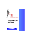
DIAS-CL Current Lockout System USER’s MANUAL User’s Manual DIAS-CL Current Lockout System Dias Geophysical Limited Dias Geophysical Limited 54 Alona Avenue Cambridge, Ontario N3C 3Y4 Canada Phone: (416) 795-1263 www.diasgeo.com [email protected] DIAS-CL v.201412. All rights reserved including the right of reproduction in whole or in part in any form. Dias Geophysical Limited, 54 Alona Avenue, Cambridge, ON, Canada. Printed in Canada. DIAS-CL Current Lockout System USER’s MANUAL User’s Manual Table of Contents Limited Warranty, Limitations of Liability and Restrictions .......................................................................... 2 1.0 Introduction ............................................................................................................................................ 3 1.1 Unpacking Your System .......................................................................................................................... 3 1.2 General Description ................................................................................................................................ 3 1.3 Interface and Indicators .......................................................................................................................... 4 1.4 Field Procedures...................................................................................................................................... 5 1.5 Support.................................................................................................................................................... 7 Limited Warranty, Limitations of Liability and Restrictions Dias Geophysical Limited hereinafter referred to as Dias, warrants that, for a period of 12 months from the delivery date to the original purchaser, Dias’ products will be free from defects in materials and workmanship. EXCEPT FOR THE FOREGOING LIMITED WARRANTY, DIAS DISCLAIMS ALL WARRANTIES, EXPRESS OR IMPLIED, INCLUDING ANY WARRANTY OF MERCHANTABILITY OR FITNESS FOR A PARTICULAR PURPOSE. Dias’ obligation is limited to repairing or replacing parts or equipment which are returned to DIAS, transportation and insurance pre-paid, without alteration or further damage, and which in Dias’ judgment, were defective or became defective during normal use. Dias ASSUMES NO LIABILITY FOR ANY DIRECT, INDIRECT, SPECIAL, INCIDENTAL OR CONSEQUENTIAL DAMAGES OR INJURIES CAUSED BY PROPER OR IMPROPER OPERATION OF ITS EQUIPMENT, WHETHER OR NOT DEFECTIVE. DIAS-CL v.201412. All rights reserved including the right of reproduction in whole or in part in any form. Dias Geophysical Limited, 54 Alona Avenue, Cambridge, ON, Canada. Printed in Canada. DIAS-CL Current Lockout System USER’s MANUAL 1.0 Introduction This manual is designed to provide instruction for the use and maintenance of the DIAS-CL current lockout system. The DIAS-CL system is designed to be integrated with the DIAS-32 DCRC (Direct Current Resistivity and Chargeability) system. The DIAS-CL system is intended to augment, and integrate with, a well-designed set of field safety practices and procedures for operation of electrical surveys. This manual is intended as both a reference and a teaching tool and it is recommended that you read the entire document. If you experience operational problems with your system, please call technical support at +1 (306) 249-4422. 1.1 Unpacking Your System Thank you for purchasing a DIAS-CL system. A packing list is included with your shipment that identifies all of the items that are in your order. You should check your shipment against the packing list upon receipt of your shipment. If you find that an item is missing or was damaged during the shipment, please call Dias immediately so that we can correct the problem. Following is a list of items that are included with your shipment: DIAS-CL current lockout units complete with internal battery Lanyards for each DIAS-CL handheld DIAS-CM-L current monitor equipped with DIAS-CL lockout technology 1.2 General Description The DIAS-CL is a lightweight, portable technology that is designed to mitigate the risk of electrocution from the high voltage wires and electrical equipment during the course of geophysical surveying. Many ground geophysical surveys involve the transmission of current at high voltage through wires that extend through the survey area, and through ground electrodes. Direct current resistivity and chargeability (DCRC) surveys often involve the laying of extensive amounts of conductive wire through the survey area. Current is transmitted through this wire repeatedly through a production survey day, and between these transmission sessions, a portion of the wire is moved by the survey crew members. Because of the large areas occupied by this type of survey (>10 km in most cases), it is a challenge to mitigate the risk of electrocution, particularly where traditional modes of communication fail. The DIAS-CL system comprises a network of personal (handheld) devices that provide each crew member who has one of the devices with overriding control over the electrical connection between the transmitter and the current transmission wire. Status information for each crew member is entered in their handheld and transmitted through the DIAS-32 mesh network to the DIAS-CM-L current monitor and to the other crew members. For the DIAS-CL system to function as intended, a DIAS-CM-L current monitor and a DIAS-32 system are required. The DIAS-CM-L device is normally installed near the transmitter operator along the current transmission wire, and is required to effect the override functionality of the DIAS-CL system through the integrated HV relay, mesh network module, and controller. The DIAS-32 system is required for transmission of the status information from each of the DIAS-CL devices to the DIAS-CM-L device. This transmission is carried through the DIAS-32 mesh network system. DIAS-CL v.201412. All rights reserved including the right of reproduction in whole or in part in any form. Dias Geophysical Limited, 54 Alona Avenue, Cambridge, ON, Canada. Printed in Canada. USER’s MANUAL DIAS-CL Current Lockout System We highly recommend that the DIAS-CL technology be integrated into a field safety system that addresses all aspects of the dangers of working with electrical equipment. The DIAS-CL technology is designed to be nested with a standard ‘power ON – power OFF’ protocol using conventional radio communication. In this way, the DIAS-CL system provides an added layer of protection for the crew against electrocution, and there will be less risk of injury as crews transition from the old transmitter protocols to the new system involving the DIAS-CL technology. 1.3 Interface and Indicators DIAS-CL Controller The DIAS-CL controller is a small, rugged, self-contained device that can be easily and quickly deployed with minimal training. The external features of the DIAS-CL controller are shown in the following image of the top surface of the handheld. Figure 1: DIAS-CL interface layout. Status Screen: Screen to display the status of the system. System Status – the status of all units is given on the left hand side – up to 10 units can be displayed. The status of each is indicated as follows: S – safe – indicates that the user is safe to be working with the wires C – clear – indicates that the user is clear of the wires and current transmission can proceed O – offline – indicates that the user is offline, and may not be clear – this status may be due to a power off condition, lack of network access, or an unserviceable device Tx – transmit - indicates that the current operator has authorised current transmission and the user must assume that current is being transmitted ID – supplies the mesh network ID for the device Unit status – displays the status of the unit using the same nomenclature as given above (S, C, O, Tx). Current – displays the average on-time current in Amperes as recorded at the DIAS-CL-L unit. Four buttons in the lower portion of the device provide the following functionality: Power: Power on/off button. Depress to power on. Depress and hold to power off. Safe: To be depressed when the user is about to approach the transmitter wire. It should be depressed when the user is still more than 3 m (5 m in some jurisdictions) from the transmitter wire, and the transmitter current is already off. In rare circumstances, this button can be depressed to effect shut-off of the transmitter current. The user should also confirm that the transmitter current is zero prior to approaching the wire and doing any work with the wire. DIAS-CL v.201412. All rights reserved including the right of reproduction in whole or in part in any form. Dias Geophysical Limited, 54 Alona Avenue, Cambridge, ON, Canada. Printed in Canada. DIAS-CL Current Lockout System USER’s MANUAL Clear: Depress when the user has completed all work with the transmitter wire and has already moved greater than 3 m away from the wire (5 m in some jurisdictions). The transmitter current can be turned on only when all units have their status set to clear. Tx: Depress when all units have ‘Clear’ status. This button must be depressed to close the relay in the DIAS-CM-L unit to allow for transmission of current through the current trasnmission wires. Normally this button is depressed by either the transmitter operator or the local current electrode operator. DIAS-CL Receiver The DIAS-CL receiver comprises a high-voltage relay, a mesh network card, a controller, a highgain antenna, and indicator lights. This receiver is currently integrated with the DIAS-CM current monitor system. DIAS-CM units that have been retrofitted to contain the DIAS-CL receiver are named DIAS-DM-L, with the ‘L’ extension on the name indicating that the unit has ‘Lockout’ functionality. The only component that must be installed is the antenna, which must be screwed into the antenna receptacle. Two status LED lights indicate the status of the DIAS-CL receiver. If the red light is on, the status is ‘Tx’, and if the green light is on, the status is ‘Safe’. These lights are provided for the benefit of the current operator to indicate what state the DIAS-CL receiver is in. 1.4 Field Procedures Following is a step-by-step description of the procedure for use of the DIAS-CL current lockout technology. Definition of Terms Current Operator – crew member who will carry current wire, lay wire, embed current electrodes in the earth, and make connections between current transmission wire and electrodes. Transmitter Operator – crew member in charge of operating the current transmitter. Receiver Operator – crew member in charge of operating the DIAS-32 receivers. DIAS-CL Receiver – Device for disengaging the path of electricity from the Current Operator. This will normally be the DIAS-CM-L unit, which embodies both the DIAS-CM current monitor and DIAS-CL receiver functionality. DIAS-CL Controller – Handheld device for remotely controlling the DIAS-CL Receiver. Pre-survey Preparation Prior to mobilization to the survey site, determine the number of DIAS-CL units that will be required for the survey. We recommend 2 to 3 spares for each survey. Test the functionality of the DIAS-CM-L and DIAS-CL controllers. Pre-operational Checks Ensure that the DIAS-CM-L current monitor and all DIAS-CL controllers are checked for battery performance on a daily basis to verify that the system is functioning properly for the intended protection of crew and equipment. This is also important because controllers DIAS-CL v.201412. All rights reserved including the right of reproduction in whole or in part in any form. Dias Geophysical Limited, 54 Alona Avenue, Cambridge, ON, Canada. Printed in Canada. DIAS-CL Current Lockout System USER’s MANUAL that become unserviceable during the course of surveys can have significant production consequences. Ensure that each crew member that will be working with the current transmission lines or that will be exposed to the current transmission wires is assigned a DIAS-CL controller. Job Steps IMPORTANT: Each step much be satisfied before proceeding to the next step of the procedure Note: Clear communications must be maintained at all times between all members of the survey crew to ensure all crew members clearly understand when power is ON and when power is OFF. 1. Initialization Procedure – each DIAS-CL controller that will be used for the survey must be paired with the DIAS-CL receiver prior to surveying. This handshake process can be carried out at any location within the network, but is perhaps best done at the DIAS-CL receiver location. With both the receiver and the controller powered on, press and hold the 'SAFE' button on the controller, then press ‘select’ on the receiver. A successful handshake will be indicated on the left hand side of the controller, at which point the 'SAFE' button on the controller can be released. 2. Each crew member must ensure they are at least 3 meters (5 m in some jurisdictions) from any potentially high voltage source. Once this condition is met, each crew member is to push 'CLEAR' on the DIAS-CL controller. The status of each crew member can be confirmed by all other crew members by viewing the left side of the screen on the controller. 3. The current operator confirms that all crew members have a ‘CLEAR’ status. 4. The current operator pushes 'TX' and confirms the system is in the 'TRANSMIT' state 5. The current operator radios “Power ON, Power ON” 6. The transmitter operator radios “Turning Power ON”, waits 5 seconds and turns on the transmitter then radios “The Transmitter is ON, The Transmitter is ON”. Each DIAS-CL controller will begin to display the average on-time amplitude of the current waveform. 7. The current operator verifies power is on by viewing the cycling red light display from a 3 meter distance or more on the DIAS-CM-L receiver. 8. When the receiver operator confirms that the IP/Resistivity measurements are completed, the receiver operator radios “Power OFF, Power OFF”. 9. The transmitter operator turns off the transmitter then radios “Transmitter is OFF, Transmitter is OFF” 10. The current operator pushes “SAFE” on the DIAS-CL controller before handling any equipment used for the purpose of transmitting electricity. 11. Any crew member who needs to approach within 3 meters (5 m in some jurisdictions) of a potentially high voltage source must push “SAFE” on their lockout controller and verify the system is in the “SAFE” state before approaching the potential high voltage source. The above steps described in 2 through 11 are repeated for each transmit sequence. The information in this procedure does not take precedence over legislation regarding the use of electrical systems in the jurisdiction(s) in which the survey is taking place. DIAS-CL v.201412. All rights reserved including the right of reproduction in whole or in part in any form. Dias Geophysical Limited, 54 Alona Avenue, Cambridge, ON, Canada. Printed in Canada. DIAS-CL Current Lockout System USER’s MANUAL 1.5 Support Dias Geophysical provides full support for the DIAS-CL technology. Technical support is available by calling +1 (306) 249-4422 and asking for Dias Technical Support Services. Unserviceable units can be packed and shipped to the following address: Dias Geophysical Limited 147 Robin Crescent Saskatoon, Saskatchewan S7L 6M3 Canada Please visit our website at www.diasgeo.com for further contact information. DIAS-CL v.201412. All rights reserved including the right of reproduction in whole or in part in any form. Dias Geophysical Limited, 54 Alona Avenue, Cambridge, ON, Canada. Printed in Canada.