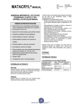
1
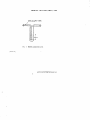
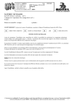
इंटरनेट
मानक
Disclosure to Promote the Right To Information
Whereas the Parliament of India has set out to provide a practical regime of right to
information for citizens to secure access to information under the control of public authorities,
in order to promote transparency and accountability in the working of every public authority,
and whereas the attached publication of the Bureau of Indian Standards is of particular interest
to the public, particularly disadvantaged communities and those engaged in the pursuit of
education and knowledge, the attached public safety standard is made available to promote the
timely dissemination of this information in an accurate manner to the public.
“जान1 का अ+धकार, जी1 का अ+धकार”
“प0रा1 को छोड न' 5 तरफ”
“The Right to Information, The Right to Live”
“Step Out From the Old to the New”
Mazdoor Kisan Shakti Sangathan
Jawaharlal Nehru
IS 13432-1 (1992): Gas leak detector for use with low
pressure liquefied petroleum gas burning appliances, Part
1: Mechanical type [MED 23: Domestic and Commercial Gas
Burning Appliances]
“!ान $ एक न' भारत का +नम-ण”
Satyanarayan Gangaram Pitroda
“Invent a New India Using Knowledge”
“!ान एक ऐसा खजाना > जो कभी च0राया नहB जा सकता ह”
है”
ह
Bhartṛhari—Nītiśatakam
“Knowledge is such a treasure which cannot be stolen”
IS 13432 ( Part 1 ) : 1992
(Reaffirmed 2002)
Indian Standard
GASLEAKDETECTORFORUSEWITHLOW
PRESSURE LIQUEFIED PETROLEUM GAS
BURNING APPLIANCES-SPECIFICATION
PART
UDC
1
MECHANICAL
TYPE
614~842,435 : 654.924-553
Q BIS 1992
BUREAU
MANAK
April 1992
OF
BHAVAN,
INDIAN
STANDARDS
9 BAHADUR
SHAH
NEW DELHI 110002
ZAFAR
MARG
Price Group 2
Domestic
and Commercial
Gas Burning Appliances
Sectional Committee,
HMD 23
FOREWORD
This Indian Standard ( Part 1 ) was adopted by the Bureau of Indian Standards, after the draft
finalized by the Domestic and Commercial Gas Burning Appliances Sectional Committee had
been approved by the Heavy Mechanical Engineering Division Council.
Liquefied petroleum
gases ( LPG ) produced
and marketed in India generally conform to
1s 4576 : 1978 ‘Specification
for liquefied petroleum gases (Jirst revision )’ and designated as
Commercial Butane/Propane
Mixture.
LPG is colourless,
odourless and being highly inflammable, a malodourant ( foul smell ) is added to detect gas leakage.
I’he gas is twice as heavy as
air and can form explosive mixture with air even in very small concentrations.
In view of the above and other safety related properties
some simpIe rules/code
need be
observed for its safe operation/installation.
Because the rules are simple, they are neglected.
Failure to observe these rules may lead to accidents of varying intensity.
The use of LPG in
individual household has been widely expanding and protection
of consumers from the hazards
arising during installation and operation is of vital interest.
Leak detector is a device used for detecting,
locating or measuring or combination
thereof.
This standard ( Part 1 ) lays down the requirements of mechanically operated Gas Leak Detectors
Electronically
operated Gas Leak Detectors
are also
used with LPG burning appliances.
avaiIable in the country and for covering their requirements
a separate standard ( Part 2 ) is
under preparation.
For the purpose of deciding whether a particular requirement of this standard is complied with,
the final value, observed or calculated, expressing the result of a test or analysis, shall be rounded
off in accordance with IS 2 : 1960 ‘Rules for rounding off numerical values (revised)‘. The number
of significant places retained in the rounded off value should be the same as that of the specified
value in this standard.
IS 13432 ( Part 1) : 1992
Indian Standard
GASLEAKDETECTORFORUSEWITHLOW
PRESSURE LIQUEFIED PETROLEUM GAS
BURNING APPLIANCES-SPECIFICATION
PART
1
MECHANICAL
Component
1 SCOPE
1.1 This standard specifies materials, construction, performance and testing requirements for
gas leak detectors
of mechanical type for use
with low pressure [ 2.942 kN/mg ( 30 gf/cmg )
nominal gas inlet pressure] liquefied petroleum
gas burning appliances.
1.1.1 For convenience
this standard
divided in two sections as follows:
Brass parts
Springs
has been
Section 1 Material and construction
Section 2 Performance
and testing
ments
Sheet metal
parts
require-
The Indian Standards listed in Annex
necessary adjuncts to this standard,
SECTION 1 MATERIALS
CONSTRUCTION
Tubes
(see IS 1545 : 1982. IS 2501 :
i985,
IS 8119 : lb76 and IS
10773 . 1983 )
AND
3.1 Components
and parts that may come in
contact with LPG shall be manufactured from
or be treated with materials compatible with
LPG as well as be unaffected by chemical or
thermal influences that may be encountered in
normal use. For guidance some appropriate
materials are specified in table below but other
type of materials may be used provided that the
of performances,
durability
and
standards
safety of gas leak detectors are not lowered.
3.2 Typical materials of various
detector are shown below:
Component
Body
Cover
Rubber parts
Plastic parts
parts
Free cutting brass ( see IS 3i7 :
1989 )
Stainless steel [ see IS 4454
( Part 4 ) : 1975 ]
Spring
steel [see
IS 4454
( Part 3 ) : 1975 ]
Phosphor bronze ( see IS 7608 :
1987 )
Cold rolled steel ( see IS 513 :
1986 )
Brass sheet (see IS 3168 : 1981)
Steel-surface treated for corrosion resistance
Brass
( see IS 319 : 1989 )
Engineering plastics
A are
AND COMPONENTS
Material
Gears
2 REFERENCES
3 MATERIAL
TYPE
3.3 Al1 copper and copper alloy parts shall pass
the mercurous nitrate
test ( season cracking
test ) when tested according to the method
specified in IS 2305 : 1988.
3.4 Non-metallic materials normally in contact
with the gas shall not swell more than 15 percent of the volume after being immersed in
pentane or LP Gas for 72 hours at room temperature, when tested according to Annex B of
IS 5116 : 1985.
3.5 The material of diaphragm,
if provided, shall
be of synthetic rubber or any other suitable
material and if it is rubber, shall satisfy the
requirements given in 3.5.1 to 3.5.6.
of the
Material
3.5.1 The material shall be free from porosity
pits and foreign particles
and shall have a
smooth, non-tacky surface with minimum taIc
or bloom.
Zinc alloy ( see IS 742 : 1981 ),
Aluminium alloy (see IS 617 :
1975 )
Aluminium alloy ( see IS 617 :
1975 ) Engineering plastics
LPG resistant rubber
Engineering plastics
3.5.2 The material shall not show change of
more than 10 IRHD when subjected
to the
accelerated
in 3 or 4 of
_ ageing test described
-_ _
IS 34UO( Part 4 ) : 1987.
1
IS 13432( Part 1) : 1992
3.5.3 The material shall be such that when an
assembled gas leak detector
is subjected to a
pressure up to 150 kPa ( l-5 kgf/cm2 ) from the
side subjected to pressure while normal working,
the diaphragm shall not pull out or burst.
3.5.4 The material shall be capable of withstanding a clamping pressure of 98 kPa ( 1 kgf/
cm2 ) where by the material itself
or the
substance with which the fabric layer has been
impregnated shall not be pressed away, flowed
away or be bruised or otherwise damaged.
3.5.5 The material shall after immersion
in
pentane or test gas as defined in Appendix A of
IS 9798 : 1981 for 72 hours, meet the requirements tabulated in Appendix D of IS 9798 : 1981.
After this test, change in hardness value from
before to after the test shall not exceed 15
IRHD [ see IS 3400 ( Part 2 ) : 1980 1.
NOTE - The test at 3.5.1 to 3.5.5 are work batch
tests. On initial seIection of a diaphragm
material,
it shall also be tested in test gas in vapour phase
for 72 hours, and shall not show a weight or volume
change greater than 15 percent.
4 CONSTRUCTION
AND WORKMANSHIP
4.1 The construction of all the parts of detector
shall be of high standard of workmanship and
finish. The construction
shall ensure durability
with leak tight joints wherever applicable
and
shall comply with 6 of this standard.
4.2 A.11gas carrying joints shall be leak tight
and resistive to a temperature of 120°C.
4.3 Screw threads, if provided
shall compIy
with the requirements
of IS 554 : 1985 or IS
2643 ( Part 1) : 1975 or IS 4218 ( Parts 1 to 4 ).
4.4 Gas leak detector
for retrofitting with gas
burning appliance shall have inlet,
and/or
outlet nozzle conforming
to 17.1 and 17.2 of
IS 5116 : 1985.
4.5 The gas carrying parts of the detectors
shall be tested with a air pressure of 14-71 kPa
150 gf/cms ) and shall not
( approximately
show any leakage.
4.6 All nuts, bolts and fittings having spanner
flats shall by capable of being tightened
or
slackened by suitable spanner or be readily
accessible to an adjustable spanner.
5 GENERAL
5.1 The detector shall be so designed that when
fitted on the LPG burning appliance there shall
not by any obstruction
or protrusion
beyond
the normal protrusion
of knobs and other
controls of the appliance.
5.2 For integral fitment model, the gas leak
detector shall have provision for fitting to gas
rail of gas burning appliances so as to give a
leak tight and durable joints.
5.3 After fitting the detector on the gas burning
appliance,
there shall be no change in the
normal operation of the gas burning appliances.
The device shall function
with the normal
pressure available in the gas rail. The detector
thus fitted for leak detection
shall not change
any of the existing requirements
of relevant
appliance standards.
5.4 The gas leak detector
when mounted with
the appliance shall detect leak from entire low
pressure installation connected to the appliance.
5.5 The detector shall also be capable of detecting a leakage of minimum 4 mmg/sec from
the system to the atmosphere at 2.942 kN/ml
( 30 gf/cm2 ) pressure.
SECTION
2
TESTING
PERFORMANCE
REQUIREMENTS
AND
6 GAS SOIJNDNESS
6.1 The detectors shall be tested for gas soundness at the room temperature by the folIowing
method.
Subject the detector to be tested to
an air pressure
of 14.71 kPa ( approx 150
gf/cme ) with the bubble leak indicator (see
Fig. 6 of IS 5116 : 1985 ) in the air supply line.
Examine the bubble indicator for the successive bubbles.
The time taken between successive bubbles shal1 not be less than one minute.
6.1.1 Resistance to High Temperature
The gas leak detector is exposed to a temperature of 120°C for a minimum period
of 30
minutes for the complete unit to attain this
It is then removed
and left
temperature.
exposed to the atmosphere until the assembIy
returns to ambient conditions, after which it is
tested according to 6.1.
6.1.2 Resistance to Low Temperature
The gas leak detector is exposed to a temperature of -20” C for a minimum period of 30
minutes for the detector to attain this temperature.
It is then removed and left exposed to
the atmosphere until the assembly returns to
ambient conditions,
after which it is tested
according to 6.1.
7 SURFACE
TEMPERATURES
7.1 The detector when fittted with the appliance
shall be fitted at a place where the temperature
does not reach 12OoC during normal working
conditions.
IS 13432 ( Part 1) : 1992
7.2 No part of the retrofitted detector with the
appliance using rubber
tubing shall exceed
a temperature of 65°C after 2 hours of normal
working of the appliance.
service conditions and could introduce
improper parameters of assessment of non-flexibles.
The test shouId relate only to the flexibles
referred to above.
8 CYCLE TEST
9 TESTING
( ENDURANCE
TEST )
8.1 When assessing a new design, a type
approval test in the form of a ON - OFF cycle
test of the gas leak detector
shall be carried
out. For the purpose of this standard one
cycle means pressurizing the detector to 2.942
kN/ma ( 30 gf/cm” ) and releasing.
A fully
assembled gas leak detector unit shall stand a
minimum of 100 000 cycles of sensor indicator
operations.
After this test the detector
shall
meet the requirements of 6.1.
8.2 For batch
acceptance
cycles shall be 20 000.
tests the
number
8.3 The purpose of the test is to evaluate the
quality of various tlexibles such as diaphragm
retention
of critical
and spring, vis-a-vis
properties relevant to function, resistance to
deformation/degradation,
loss of flexibility
This
under condition of flexing and unflexing.
test does not purport to check any mechanical
requirements of the construction/assembly
and
should not be taken as representative
of actual
OF THE DETECTOR
Each leakage detector
shall be tested for its
calibration by creating an artificial known leak
by suitable method to check sensitivity according to 5.5.
10 MARKING
10.1 Detector shall be clearly and permanently
marked with the following:
a) Manufacturer’s
name, initials or registered trade-mark;
b) Number of this standard;
cl The words ‘For use with liquefied petroleum gases at 2.942 kN/m* ( 30 gf/cm’ )
nominal pressure; and
Any
other markings agreed to between
d)
the purchaser and the manufacturer.
10.1.1
BIS Certification Marking
Details available
Standards.
with the
Bureau
of Indian
IS 13432( Part 1) : 1992
ANNEXA
( Clause 2 )
LIST OF REFERRED
Title
319 : 1989
Free cutting brass, rods and
sections - Specification (fourth
revision)
513 : 1986
Cold-rolled
low carbon steel
sheets and strips ( third rev&on )
554 : 1985
Dimensions
for pipe threads
where pressure tight joints are
required on the threads ( third
revision )
3168 : 1981
Title
Zinc base alloy die castings
( second revision)
1545 : 1982
Solid drawn copper alloy tubes
for condenser and heat exchangers ( ( second revision)
2305 : 1988
Method for mercurous
test for copper and
alloys (first revision )
2501 : 1985
tubes
for
Copper
engineering
purposes
vision )
Brass strip and foil for
drawing (first revision)
Method
3400
( Parts 1 to 10 ) rubbers
4218 ( Parts 1
t04j:
1976
4:;;$
Aluminium
and
aluminium
alloys ingots and castings for
general engineering
purposes
( second revision )
742 : 1981
2;;;(
STANDARDS
IS No.
IS No.
617 : 1975
INDIAN
deep
of test for vulcanized
1SO metric screw threads
formed
Part 3 ) : Steel wires for cold
springs: Part 3 Oil hardened and
tempered steel wires alloyed
( first revision )
4:;;5’ Part 4 ) : Steel wires for cold formed
springs: Part 4 Stainless spring
steel wire for normal corrosion
resistance (first revision)
.
5116 : 1985
requirements
for
General
domestic and commerial equipment for use with LPG (second
revision )
nitrate
copper
7608 : 1987
Phosphor
bronze
general engineering
( jirst revision )
general
(second
8119 : 1976
Copper brazed steel tubing
9798 ; 1981
Specification for low pressure
regula’tors k% use with TLPG
mixtures
for pipe threads
Part 1) : Dimensions
for fastening purposes : Part 1
Basic profile and dimensions
(first revision )
10773 : 1983
4
wire for
purposes
Copper tubes for refrigeration
purposes
--Standard Mark
The use of the Standard Mark is governed by the provisions of the Burtm ofIndian
Standards
Act,1986and the Rules and Regulations made thereunder. The Standard Mark
on products covered by an Indian Standard conveys the assurance that they have been
produced to comply with the requirements of that standard under a well defined system
of inspection, testing and quality control which is devised and supervised by UIS and
operated by the producer.
Standard marked products are also continuously checked by
BIS for conformity to that standard as a further safeguard.
Details of conditions under
which a licence for the use of the Standard Mark may be granted to manufacturers
or
producers may be obtained from the Bureau of Indian Standards.
Bureau of Indian Standard
established under the Bureau of Indian Standards Act, 1986 to
BIS is a statutory
institution
promote harmonious
development
of the activities of standardization,
marking and quality
certification of goods and attending to connected matters in the country.
Copyright
BIS has the copyright of all its publications. No part of these publications
may be reproduced
in any form without the prior permission in writting of BIS. This does not preclude the free use,
in the course of implementing the standard, of necessary details, such as symbols and sizes, type
or grade designation.
Enquiries
relating
to copyright
be addressed
to the Director
( Publications ), BIS.
Revision of Indian Standards
Indian Standards are reviewed periodically
and revised, when necessary and amendments, if
any, are issued from time to time. Users of Indian Standards should ascertain that they are in
Comments on this Indian Standard may be
possession of the latest amendments or edition.
sent to BIS giving the following reference:
Dot : Noa HMD 23 ( 0060 )
Amendments Issued Since Publication
Amend No.
Date of Issue
Text Affected
BUREAU OF LNDIAN STANDARDS
Headquarters:
Manak Bhavan, 9 Bahadur Shah Zafar Marg, New Delhi 110002
Telephones : 331 01 31, 331 13 75
Telegrams
( Common
: Manaksanstha
to all Offices )
Regional Offices :
Central : Manak Bhavan, 9 Bahadur
NEW DELHI 110002
Eastern
Telephone
Shah Zafar Marg
: l/l4
C. I. T. Scheme VII M, V. I. P. Road, Maniktola
CALCUTTA 700054
Northern
: SC0 445-446, Sector 35-C, CHANDIGARH
160036
Southern
: C. I. T. Campus, IV Cross Road, MADRAS
600113
Western
: Manakalaya,
Branches
E9 MIDC, Marol, Andheri ( East )
BOMBAY 400093
33101 31
E331 13 75
37 84 99, 37 85 61,
r 37 86 26, 31 85 62
53 38 43, 53 16 40,
53
23 84
i
41 24 42, 41 25 19,
I 41 23 15, 41 29 16,
632 9295,
63 27 80,
632 78 92
: AHMADABAD,
BANGALORE,
BHOPAL, BHUBANESHWAR,
COIMBATORE
FARIDABAD,
GHAZIABAD, GUWAHATI,
HYDERABAD, JAIPUR,
KANPUR,
LUCKNOW, PATNA, THIRUVANANTHAPURAM.
Printed at Printwell Printers, Aligarb, India
AMENDMENT
NO. 1 SEPTEMBER
1996
TO
IS 13432 ( Part 1) : 1992 GAS LEAK DETECTOR
FOR USE WITH LOW PRESSURE LIQUEFIED
PETROLEUM
GAS BURNING APPLIANCES
SPECIFICATION
FART
1
MECHANICAL
( First cover page and page 1 ) -
Substitute
TYPE
the following
for the existing
title:
‘GAS LEAK INDICATOR FOR USE WITH LOW
PRESSURE LIQUEFIED PETROLEUM
GAS
BURNING APPLIANCES
- SPECIFICATION
PART
( AIZpages, General ) appears.
1
MECHANICAL
TYPE ’
Substitute word ‘indicator’ jor ‘detector’ wherever
( Second cower page, Foreword ) -
Insert the following
aCtcr fourth para:
‘At present the products covered under this standard shall be certified along with
the appliance and individual product certification shall be considered later.’
(Puge
1, clultse 3.5, lust line ) -
(Page 2, clause 4.4 ) -
Substitute
Delete.
( Page 2, clause 5.2, first line ) model’.
(Page
“5.5
2, clause 5.5 ) -Substitute
Sensitivity
‘3.55’ for ‘3.5.6’.
Delete the words ‘For integral fitment
the following
for the existing:
of Leak indicator
The indicator shall be capable of detecting a leak of one bubble per 25 seconds
when tested according to Annex I3 at a pressure of 2.942 kN/m* (30 gf/cm*) and
with the appliance. The indicator shall show ‘Leak’ when the time taken between
successive bubbles is less than 25 seconds. The indicator shall not show ‘Leak’
when the time taken between successive bubbles is more than 25 seconds.
Amend No. 1 to IS 13432 ( Part 1 ) : 1992
5.6 The dial shall indicate the words ‘ Normal’ and ‘Leak’ so that the consumer
gets instant indication for preventive action. ‘Normal’ and ‘Leak’ indication may
also be indicated by green and red colours respectively.
5.7 Each leak indicator shall be supplied with an user’s manual giving all the
details for installation, principle of working, method of operation for finding the
leak and the following limitations:
a)
Does not locate the leak,
b)
Does not prevent the leak,
c)
Does not gi:rc audible alarm,
d)
Does not indicate leak when the appliance is in operation,
e)
Works only under the specified procedures,
f)
Calibration
g)
Leakage indication according to the time :uent.ioncd in this manual.”
at a pressure of 2.942 kNjm2 (30 gf/cm’), and
(Page 3, clalr.sc 7.2 ) -- DCM~.
(Pn~e 4, Annex A) -
Insert the following Annex at the end:
“ANNEX
( Chlsc
8
5.5 )
n-1 Procedure
B-l.1 Test the Appliance for Sensitivity hy the Following Method
B-1.1.$ Subject ihe appliance to be tested to an air supply at a pressure of 2.942
mfrn (30 gflcm ) with the bulkk leak indicator ( see Fig. I ) \n OK air supply
line. Adjust the time between two successive bubbles as 25 seconds by creating
an artificial leak through needle valve or any other device. Cut off the air supply
to the appliance to confine system pressure. Then observe the indication in the
gas leak indicator.
2
Amend
6mm
FIG. 1
No.
ID GLASS
1 to IS 13432 (Part
1) : 1992
TUBING
BUHIEL LEAK IND!CATOH
(HMD23)
Reprography
IJnic,131S,
New Delhi, India