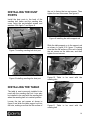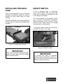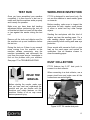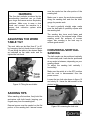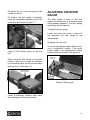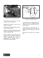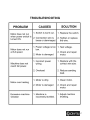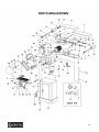
1
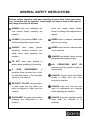
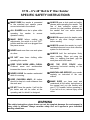
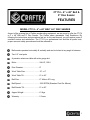
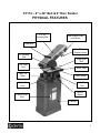
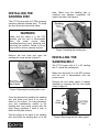
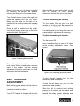
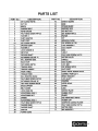
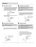
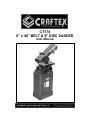
CT174 6” x 48” BELT & 9” DISC SANDER User Manual TABLE OF CONTENTS General Safety Instructions ..........................................................................3 Specific Safety Instructions...........................................................................4 CT174 Features............................................................................................5 Physical Features .........................................................................................6 Unpacking ....................................................................................................7 Proper Grounding .........................................................................................7 Installing the Sanding Disc ...........................................................................8 Installing the Sanding Belt ............................................................................8 Belt Tracking Adjustment..............................................................................9 Installing the Dust Ports................................................................................10 Installing the Work Table ..............................................................................10 Installing the Back Stop ................................................................................11 On/Off Switch ...............................................................................................11 Test Run .......................................................................................................12 Work-Piece Inspection..................................................................................12 Adjusting the Work Table Tilt........................................................................13 Sanding Tips.................................................................................................13 Horizontal/Vertical Sanding ..........................................................................13 Adjusting the Miter Gauge ............................................................................14 Maintenance .................................................................................................15 V-Belt Tension & Replacement.....................................................................15 Troubleshooting............................................................................................17 Parts Breakdown ..........................................................................................18 Parts List ......................................................................................................19 Warranty .......................................................................................................20 2 GENERAL SAFETY INSTRUCTIONS Extreme caution should be used when operating all power tools. Know your power tool, be familiar with its operation, read through the owner’s manual and practice safe usage procedures at all times. ALWAYS read and understand the user manual before operating the machine. router bits, shaper heads, blades, knives or making other adjustments or repairs. CONNECT your machine ONLY to the matched and specific power source. NEVER leave a machine unattended while it is in running. ALWAYS wear safety glasses respirators, hearing protection and safety shoes, when operating your machine. NEVER reach over the machine when it is in operation. DO NOT wear loose clothing or jewelry when operating your machine. A SAFE ENVIRONMENT is important. Keep the area free of dust, dirt and other debris in the immediate vicinity of your machine. ALWAYS keep blades, knives and bits sharpened and properly aligned. ALL OPERATIONS MUST BE performed with the guards in place to ensure safety. ALWAYS use push sticks and feather boards to safely feed your work through the machine. BE ALERT! DO NOT use prescription or other drugs that may affect your ability or judgment to safely use your machine. ALWAYS make sure that any tools used for adjustments are removed before operating the machine. DISCONNECT the power source when changing any components of the machine. ALWAYS keep the bystanders safely away while the machine is in operation. 3 C174 – 6”x 48” Belt & 9” Disc Sander SPECIFIC SAFETY INSTRUCTIONS MAKE SURE the sander is connected to the matched and specific power source instructed in the manual. ALL GUARDS must be in place while operating the sander to ensure operator’s safety. MAKE SURE before making any adjustments, the switch is in the “OFF” position and the cord is un-plugged from the power source. NEVER sand more than one work piece at a time. ALWAYS wear a dust mask and safety glasses while operating the sander. The use of dust collection system will remove tiny dust particles produced by the sander that can cause serious health problems. ALWAYS inspect stock for staples, nails knots or any other foreign material before sanding. ALWAYS operate the sander in a wellventilated area and use a dust collection system for dust removal. DO NOT wear loose clothing while operating this sander. ALWAYS hold the work-piece firmly when sanding. When not using the table, i.e. sanding free-hand, grip the work piece with both hands. KEEP YOUR WORK AREA CLEAN. Cluttered areas and workbenches increase the chance of accident. USE THE STOP FENCE when performing horizontal sanding on the belt sander. NEVER LEAVE the sander unattended while it is running. MAINTAIN AND SERVICE your sander regularly as instructed in the user manual. KEEP CHILDREN AWAY. All visitors should be kept at a safe distance from the work area. DO NOT force the sander. It will do the job better and will be safer at the operating rate for which it is designed. MAKE SURE you have read and understood all the safety instructions in the manual and you are familiar with your CT174 sander, before operating it. If you fail to do so, serious injury could occur. WARNING The safety instructions given above can not be complete because the environment in every shop is different. Always consider safety first as it applies to your individual working conditions. CT174 – 6” x 48” Belt & 9” Disc Sander FEATURES MODEL CT174 – 6” x 48” BELT & 9” DISC SANDER As part of the growing line of Craftex woodworking equipment, we are proud to offer the CT174 a 6” x 48” Belt and 9” Disc Sander. The Craftex name guarantees Craft Excellence. By following the instructions and procedures laid out in this user manual, you will receive years of excellent service and satisfaction. The CT174 is a professional tool and like all power tools, proper care and safety procedures should be adhered to. Belt sander operates horizontally & vertically and can be locked at any angle in between Two 2.5” dust ports A precision aluminum table with miter gauge slot Motor ................................... ..........3/4-HP, 120-V Disc Diameter ...................... .......... 9” Work Table Size .................. .......... 12” x 6” Work Table Tilt .................... .......... 0° to 45° Belt Size .............................. ..........6” Wide x 48” Long Belt Speed ........................... .......... 1020 SFPM (Standard Feet Per Minute) Belt Sander Tilt .................... .......... 0° to 90° Approx Weight ..................... .......... 61 Kgs Warranty .............................. .......... 2 Years 5 CT174 – 6” x 48” Belt & 9” Disc Sander PHYSICAL FEATURES 6” x 48” Sanding Belt Belt Guard Cover Lock Knob Backstop Quick Release Tension Lever 9” Sanding Disc Table Stop Bolt 2.5” Dust Port Work Table Table Tilt Scale Miter Gauge Table Tilt Lock 2.5” Dust Port On/Off Switch Cabinet Door Lock Cabinet 6 UNPACKING The machine is properly packaged and is shipped completely in a crate for safe transportation. When unpacking, carefully inspect the crate and ensure that nothing has been damaged during transit. Open the crate and check that the machine is in good condition. WARNING CT174 is a heavy machine, do not overexert yourself. Use fork truck or other mechanical devices for safe moving. PROPER GROUNDING Grounding provides a path of least resistance for electric current to reduce the risk of electric shock. This sander is for use on a normal 120-volt circuit and is factory-equipped with a specific electric cord and plug to permit connection to a proper electric circuit. Make sure that the sander is connected to an outlet having the same configuration as the plug. If an adaptor plug is used, it must be attached to the metal screw of the receptacle. To prevent electrical hazards, have a qualified electrician ensure that the line is properly wired. Figure-1 120-Volts Outlet for CT174 It is strongly recommended not to use extension cords with your CT174. Always try to position your machine close to the power source so that you do not need to use extension cords. WARNING Improper connection of the equipmentgrounding conductor can result in a risk of electric shock. Check with a qualified electrician if you are in doubt as to whether the outlet is properly grounded. In case it is necessary to use an extension cord, make sure the extension cord does not exceed 50-feet in length and the cord is 14-gauge to prevent motor damage. Your CT174 is equipped with a cord having 3-prongs which fits a 3 prong grounding receptacle as shown in figure-3. Do not remove the grounding prong to fit it into a 2pronged outlet. Always check with a qualified electrician if you are in doubt. 7 INSTALLING THE SANDING DISC plate. Make sure the sanding disc is centered and adheres completely flat against the plate. See figure-3. The CT174 comes with a 9” PSA (pressure sensitive adhesive backed disc). To install the disc follow the instructions below. WARNING Make sure the switch is in the OFF position and the cord is disconnected from the power source when installing/removing parts, adjusting and servicing the machine. Failure to do so may result in serious personal injuries. Figure-3 Installing the sanding disc Remove the lock knob and open the sanding disc cover shown in figure-2. INSTALLING THE SANDING BELT The CT174 comes with a 6” x 48” sanding belt. To install the sanding belt: Make sure the switch is in the OFF position and the cord is disconnected from the power source. Remove the belt safety guard (if already installed) by removing the four lock knobs shown in figure-4. Figure-2 Opening the sanding disc cover Clean the plate before installing the sanding disc and make sure there is no dust or debris on its surface. You may experience poor and unsatisfactory results, or the sanding disc may loose contact with the plate during operation if there is dust or debris on the plate surface. Peel the paper at the back of the sanding disc and install the sanding disc on to the Figure-4 Removing the belt safety guard 8 Remove the dust port (if already installed) by removing the screws and washers securing the dust port to the sander frame. Turn the belt tension lever to the right and install the sanding belt onto the rollers. Make sure the arrow on the back of the sanding belt is positing towards the sanding disc. Once the belt is installed onto the rollers, turn the belt tension lever back to the left to tension the belt. See figure-5. When installing a new sanding belt, you will need to perform the belt tracking adjustment to center the belt on the rollers. To check the sanding belt tracking: Turn the sander ON and see if the belt wanders to the left or right. Be prepared to immediately turn OFF the machine. If the sanding belt is not riding the rollers on a centered path, adjustment is necessary. To adjust the sanding belt tracking: Turn the sander ON. Insert a small hex key into one of the holes in the tracking adjustment wheel. See figure-6. Figure-5 Sanding belt installed The sanding belt should be centered on both rollers. Before installing the removed parts of the sander, the belt tracking adjustment should be performed to check and adjust the belt if necessary. BELT TRACKING ADJUSTMENT Belt tracking means where the belt rides on the rollers. The belt should always be centered on both the rollers. Your CT174 sander is shipped with the belt tracking mechanism properly adjusted. Figure-6 Belt tracking adjustment wheel To track the belt towards you, turn the adjustment wheel downwards. To track the belt away from you, turn the adjustment wheel upwards. When the belt is centered and tracking properly on the rollers, stop the sander and re-install the safety guards, backstop and the dust port removed previously. 9 INSTALLING THE DUST PORTS the rod is facing the two set screws. Then tighten the two set screws. See figure-9. Install the dust ports to the back of the sanding belt frame and the sanding disc cover using the pre-installed screws and washers. See figure-7 and figure-8. Figure-9 Installing the table support rod Figure-7 Installing sanding belt dust port Figure-8 Installing sanding disc dust port Slide the table support on to the support rod as shown in figure-10 & figure-11 making sure that the flat surface of the rod is facing the set screws on the table arm, and then tighten the set screws. Figure-10 Table to be used with the sanding disc INSTALLING THE TABLE The table is most commonly installed to be used with the sanding disc but it can also be installed to be used with the sanding belt when the sanding belt is in vertical position. Loosen the two set screws at shown in figure-9 and slide the table support rod into the hole, making sure that the flat surface of Figure-11 Table to be used with the sanding belt 10 INSTALLING THE BACK STOP When the sanding belt is set for horizontal sanding, the backstop should be used to prevent the work piece flying out while sanding. Install the backstop to the sanding platen as shown in figure-12 using screw and washer provided. ON/OFF SWITCH CT174 is equipped with a rocker-type power switch which starts and stops the motor and is located on sanding disc side on the base of the sander. The switch features a removable locking key to prevent unauthorized operations. When the sander is not in use for a long period of time, simply remove the locking key and store it in a safe place. To start the sander, insert the locking key and shift the switch to the right. Figure-12 Installing the backstop Figure-13 ON/OFF switch IMPORTANT Make sure to remove the backstop when using the work table with the sanding belt in vertical position. IMPORTANT To prevent any type of accidental injuries, make sure the power switch is in the OFF position before connecting the sander to the power source. 11 TEST RUN WORK-PIECE INSPECTION Once you have assembled your machine completely, it is then time for a test run to make sure that the machine works properly and is ready for operation. CT174 is designed to sand wood only. Do not use this machine to sand metals, glass or stone etc. Make sure you have done belt tracking adjustment before performing the test run so that the belt does not come off the rollers or jam against the sander during the test run. Remove all the tools and objects used for the machine set up and installation before the test run. During the test run if there is any unusual noise coming from the machine or the machine vibrates excessively, stop the machine immediately and disconnect the cord from the power source. Investigate to find out the problem with your machine. See page-17 for TROUBLESHOOTING Before sanding, make sure to inspect the work-piece for nails, staples, small pieces of stone or metal and any other foreign objects. Sanding the work-piece with this kind of objects can tear the sanding paper. For a safe sanding always inspect your workpiece carefully before cutting and wear eye protection. Some woods with excessive finish or glue load up the sand paper and reduce its usefulness. Use an abrasive cleaner to clean the sanding paper. DUST COLLECTION CT174 features two 2-1/2” dust ports to connect to a dust collector. READ THE MANUAL When connecting to a dust collector, use a proper sized hose and make sure all the connections are sealed tightly. Before starting the sander, make sure that you have read and understood the manual and you are familiar with the functions and safety features on this machine. Failure to do so may cause serious personal injury. Figure-14 CT174 sander dust ports 12 WARNING The fine dust particles produced by the woodworking machines can go inside your lungs and cause serious respiratory problems. Make sure to wear a dust mask and connect the machine to a proper dust collection system while operation. ADJUSTING THE WORK TABLE TILT The work table can be tilted from 0° to 45° by loosening the lock knob shown in figure15 and tilting the table to the desired angle as indicated on the table scale and retighten the lock knob. must be sanded on the roller portion of the sanding belt. Make sure to move the work-piece equally along the sanding belt and use the miter gauge for precise work. To sand a perfectly straight edge, make sure the belt table is perfectly square with the sanding belt. The sanding disc turns much faster and removes more of the external edge. When sanding small flat surfaces or convex edges, disc sanding is the best way to achieve good results. HORIZONTAL/VERTICAL SANDING The belt sander can be positioned vertically or horizontally and it can also be positioned at any angle in between, depending on your sanding needs. To adjust the sanding belt vertically / horizontally: Make sure the switch is in the OFF position and the cord is disconnected from the power source. Figure-15 Tilting the work table Loosen the two lock nuts shown in figure-16 and slowly lift / lower the belt sander to the desired angle. SANDING TIPS When sanding a flat surface, firmly hold the work-piece with both hands, keeping your fingers away from the sanding belt. External curves must be sanded on the flat portion of the sanding belt. Internal curves Figure-16 Loosening the lock nuts 13 Re-tighten the lock nuts securing the belt sander in position. To position the belt sander horizontally, lower the belt sander completely until it sits on the stop bolt shown in figure-17. ADJUSTING THE MITER GAUGE The miter gauge is used to hold and support the work-piece at a desired angle during sanding operation. The miter gauge body angle can be adjusted. To adjust the miter gauge: Loosen the lock knob shown in figure-18 and reposition the miter gauge to the desired angle. Re-tighten the lock knob. Figure-17 Belt sander sitting on the stop bolt To set the miter gauge square with the disc, use a combination square. If the angle pointer needs to be repositioned, loosen pointer screw and readjust. See figure-19. When using the belt sander in horizontal position, make sure to install the backstop to the sanding frame, so that the work-piece does not fly out. See figure-18. Figure-19 Miter gauge Figure-18 Backstop installed while using the sanding belt in horizontal position 14 MAINTENANCE During the lifetime of your machine, you will need to practice some regular maintenance to keep your saw in peak performance condition. WARNING Make sure the machine is turned OFF and the cord is disconnected from the power source before installing/removing and servicing any component of the machine. The sander should be checked daily for loose mounting bolts, damaged or worn belt or disc, damaged cord or plug, worn or damaged wires and any other unsafe condition before use. V-BELT TENSION & REPLACEMENT The V-belt is pre-installed and tension at the factory. It stretches with use and should be checked regularly for proper tension and belt condition. To replace and tension the V-belt: Turn the switch to OFF position and disconnect the cord from the power source. Remove the work table if it is installed to the sanding disc. Loosen the lock knob and open the sanding disc cover. See figure-20. Remove the sanding disc and remove the screw securing the sanding disc plate and remove the plate. Clean the machine daily after use and when the machine is not in use turn the switch off and remove the switch key. A build-up of dust in the motor can cause motor damage. Periodic cleaning of the motor is not only recommended, but also mandatory for normal sanding performance. All bearings are permanently lubricated and require no further lubrication. The moisture from the wood dust remaining on the table surface can cause rust. The table and other un-painting surfaces of the machine should be cleaned and wiped after every use to make sure that there is no moisture against bare metal surface. Figure-20 Opening the sanding disc cover Loosen the four motor mounting lock nuts securing the motor. (two other lock nuts not shown in figure-21) 15 Figure-21 Motor mounting lock nuts Figure-22 Correct belt tension At this point the V-belt should be loose enough to slip it off the pulleys. Replace the V-belt with a new one and install it on the pulleys. Re-install the sanding disc plate and secure it with the screw removed. Tension the V-belt by moving the motor away from the sanding disc and tighten the motor mounting lock nuts. Push the center of the V-belt with your finger as shown in figure-22 to check the tension on the drive belt. The belt is correctly tensioned when there is approximately 1/4" deflection when it is pushed with moderate pressure. If the deflection is not approximately 1/4" when you push with moderate pressure, loosen the motor mounting nuts and retension the belt. If the deflection is approximately 1/4”, reinstall the sanding disc, and close the sanding disc cover securing it with the knob. Re-install the work table to the sanding disc. 16 TROUBLESHOOTING 17 18 19 WARRANTY CRAFTEX 2 YEARS LIMITED WARRANTY Craftex warrants every product to be free from defects in materials and agrees to correct such defects where applicable. This warranty covers two years for parts and 90 days for labour (unless specified otherwise), to the original purchaser from the date of purchase but does not apply to malfunctions arising directly or indirectly from misuse, abuse, improper installation or assembly, negligence, accidents, repairs or alterations or lack of maintenance. Proof of purchase is necessary. All warranty claims are subject to inspection of such products or part thereof and Craftex reserves the right to inspect any returned item before a refund or replacement may be issued. This warranty shall not apply to consumable products such as blades, bits, belts, cutters, chisels, punches etceteras. Craftex shall in no event be liable for injuries, accidental or otherwise, death to persons or damage to property or for incidental contingent, special or consequential damages arising from the use of our products. RETURNS, REPAIRS AND REPLACEMENTS To return, repair, or replace a Craftex product, you must visit the appropriate Busy Bee Tools showroom or call 1800-461-BUSY. Craftex is a brand of equipment that is exclusive to Busy Bee Tools. For replacement parts directly from Busy Bee Tools, for this machine, please call 1-800-461-BUSY (2879), and have your credit card and part number handy. All returned merchandise will be subject to a minimum charge of 15% for re-stocking and handling with the following qualifications. Returns must be pre-authorized by us in writing. We do not accept collect shipments. Items returned for warranty purposes must be insured and shipped pre-paid to the nearest warehouse Returns must be accompanied with a copy of your original invoice as proof of purchase. Returns must be in an un-used condition and shipped in their original packaging a letter explaining your reason for the return. Incurred shipping and handling charges are not refundable. Busy Bee will repair or replace the item at our discretion and subject to our inspection. Repaired or replaced items will be returned to you pre-paid by our choice of carriers. Busy Bee reserves the right to refuse reimbursement or repairs or replacement if a third party without our prior authorization has carried out repairs to the item. Repairs made by Busy Bee are warranted for 30 days on parts and labour. Any unforeseen repair charges will be reported to you for acceptance prior to making the repairs. The Busy Bee Parts & Service Departments are fully equipped to do repairs on all products purchased from us with the exception of some products that require the return to their authorized repair depots. A Busy Bee representative will provide you with the necessary information to have this done. For faster service it is advisable to contact the nearest Busy Bee location for parts availability prior to bringing your product in for repair. 20