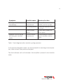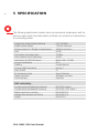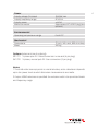
1
1
cBA 100M-1100 10 KHZ to
100 MhZ 1.1 KW amplifier
user Manual
601-294A
cBA 100M-1100 10 KHZ to
100 MhZ 1.1 KW amplifier
USER Manual
CBA 100M-1100 User Manual
contentS
1
Safety information 2Introduction
2.1 CBA 100M-1100 Introduction
3
Unpacking and installation
3.1Unpacking
3.2Installation
4Operation
5
Specifications
6Warranty
7Adresses
5
7
7
9
9
9
12
16
18
20
1Safety Information
This apparatus has been designed and tested in accordance with BS EN 61010-1,
and has been supplied in a safe condition. This manual contains some information warnings which must be followed to ensure safe operation, and to retain
the apparatus in a safe condition.
This apparatus does not incorporate components liable to explode or implode
during normal operating conditions. In normal operating conditions this apparatus does not liberate injurious or poisonous gases.
Sound levels of this apparatus after installation in a rack are below 85 dBA,
as required by EN 61010-1. However local regulations may have a lower limit
or the system as a whole may exceed the local limit. In this case appropriate
action should be taken, ie of use of any protective equipment required by local
regulations.
This apparatus is of installation category 2.
5
6
This apparatus is capable of delivering harmful levels of
radio frequency power. Ensure at all times during operation that the RF output is properly terminated with an
adequately rated termination or transducer, and that the
cables and connectors attached to the apparatus are in
good condition.
The mains plug shall only be inserted in a socket outlet
provided with a protective earth contact. The protective
action must not be negated by the use of an extension
cord without a protective conductor.
The opening of covers or removal of parts is likely to
expose live parts.
This apparatus must be disconnected from all voltage
sources before it is opened for adjustment, replacement,
maintenance or repair.
Make sure that only fuses of the required rated current
and of the specified type are used for replacement. The
use of makeshift fuses and the short-circuiting of fuse
holders is prohibited.
CBA 100M-1100 User Manual
2Introduction
CBA 100M-1100 Introduction
The CBA 100M-1100 is an amplifier capable of supplying 1.1 kW into a 50 ohm
load over the frequency range 10 kHz to 100 MHz, during the course of EMC
tests on electrical equipment. The amplifier is designed with sufficient gain
such that it may be used with normal output levels of signal sources. A safety
interlock on the rear panel is also provided, which will mute the amplifier when
grounded.
The unit is powered from a switched mode power supply for high efficiency,
high power factor and wide voltage range operation. The unit is air cooled with
integral fans, and is protected against faulty cooling by excess temperature
sensing.
A front panel indicator is provided to indicate over-temperature. The amplifier is
designed for rugged operation into a variety of loads. The amplifier is primarily
intended for use as a power source for EMC susceptibility testing, but is also
applicable to other systems requiring a wide-band linear amplifier.
This amplifier is designated as ‘professional equipment’ and should not be
operated by untrained staff.
As this product has the capability to generate high levels of RF energy it is not
intended for use in a residential environment.
Potential or theoretical hazards.
7
8
Threat
Precaution
Exposure of personnel to high RF fields Ensure that the antenna is inside a
produced by an antenna connected to screened enclosure and fit an interlock
the output of the amplifier.
to the entry door to prevent access
while the amplifier is operating.
RF burns caused by contact with the Ensure that the antenna is inside a
antenna connected to the output of screened enclosure and fit an interlock
the amplifier.
to the entry door to prevent access
while the amplifier is operating.
Amplifier self oscillation caused by This is an unlikely but theoretical
feedback from un-terminated con- possibility. Always ensure that the
amplifier input is terminated either
nectors.
by the system signal generator or by
a suitable RF load/attenuator before
switching the amplifier on.
Arcing due to high RF voltages present Always ensure that the output of the
at the output connector.
amplifier is terminated either by the
system antenna or a suitable high
power RF load or attenuator.
CBA 100M-1100 User Manual
3Unpacking and installation
3.1 Unpacking
The CBA 100M-1100 should contain the following items housed in a 19 inch
34 U rack:
Amplifier switch unit
Amplifier module Amplifier input/output module Amplifier power unit
1
4
1
1
Plus the following documentation:
CBA 100M-1100 Operating manual (this document)
Certificate of calibration 1
1
Check that the equipment is complete as in the packing list above. If any signs
of damage are found inform Teseq and do not install or use the instrument. If
the shipping carton has been damaged, retain the shipping carton and packing
material for the inspection by the carrier.
3.2 Installation
This instrument must be earthed.
9
10
If supplied with 3-phase mains in star connection, a neutral line must
be supplied.
In delta configuration, no neutral is required.
This equipment is intended for rack mounting, using suitable tray and runners
etc. The individual modules must not be mounted only by the front panels.
Typically, the amplifier will be supplied ready assembled in a cabinet. However,
if supplied in separate units for shipping convenience, the assembly procedure
is as below.
Arrangement of modules in cabinet.
This amplifier is supplied with a 34 U instrument rack ready for the insertion
of the modules.
The modules should be arranged with the power unit at the bottom, then two
amplifier units, then the amplifier input/output unit, then two further amplifier
units, and finally the amplifier switch unit. The amplifier units are distinguished
only by the length of DC supply cable, and so should be ordered from bottom
to top such that the unit with the shortest supply cable is at the bottom, and
the unit with the longest supply cable is at the top. For convenience and ease
of assembly, a 1U spacer panel is supplied for insertion between each unit.
Cable connection
Connect the centre unit supply cable from the power unit to the centre unit.
Connect each of the amplifier modules to the power unit using the connectors
and cables supplied. Connect the SMA to SMA RF cables from each of the
outputs on the centre unit, to the connectors on each of the amplifier units, and
similarly for the N to N cables The order of connection is arbitrary. Connect the
BNC to BNC cables from the centre unit to each of the amplifier units.
CBA 100M-1100 User Manual
Mains input is via a pre-wired IEC 60309 3-phase plug.
Star configured supplied with a 5 pin plug.
Delta configured supplied with a 4 pin plug
If the plug requires rewiring, brown and 2 black wires are 3-phase line, blue is
neutral when used in star (unused in delta configuration) and green/yellow for
earth.
The amplifier safety mechanism is a circuit breaker. The switch unit is supplied
from the power unit via the power breaker, located on the rear panel of the
power unit. Connect the cable from the switch unit to the power unit 7 pin
socket.
The remaining connectors are: RF input, RF output and BNC interlock. The use
of the interlock is optional, and the amplifier will operate normally with this
connector left unterminated. If an attachment is made to the BNC interlock,
ensure that the connector is a 50 ohm type and that a high quality coaxial cable
is used for connection to the switch.
Make sure that the amplifier is located in a situation with adequate ventilation.
During operation, the amplifier will draw as much as 6 kVA from the mains.
Ensure that the environment of the amplifier does not cause warm air from the
fans to be cycled back into the amplifier.
11
12
4Operation
Mains switch (on amplifier switch unit)
Operating the mains switch located on the rear of the power supply unit will
apply power to the system. The amplifier can now be switched on and off using
the push button located on the front panel.
Power indicator (on amplifier centre unit)
This indicator will illuminate when the mains switch is turned on, and power
is available from the mains. Indicators are also fitted to the power unit and
amplifier units.
Safety interlock indicator (on amplifier centre unit)
With a short circuit applied to the safety interlock connector on the rear panel,
this indicator will illuminate and the amplifier gain stages will all be turned off.
The fans will continue to operate.
A short circuit applied to this connector also functions as a fault reset (see entry
under “Fault Indicator”).
Fault indicator (on amplifier centre unit)
The amplifier protects itself from the following faults:
Excess module temperature
Air cooling failure (through faulty fan or blocked vent)
Partial power supply failure (loss of phase or PSU failure)
In the case of one of these faults occurring the fans will continue to operate.
The fault state is indicated by the illumination of the red fault indicator.
The behaviour of the amplifier under these circumstances provides a first level
diagnostic to the fault, as described in table 1.
CBA 100M-1100 User Manual
13
Symptom
Possible cause
Course of action
Fault light illuminates
immediately
Excess module
temperature
Let amplifier fans run for
a while, and re-try later
Air-cooling failure
Check fan operation and
air vents
Power supply
failure
Check mains supply for
interruption
Excess module
temperature
Check ambient temperature of amplifier environment
Amplifier runs for a while
and then goes into fault
mode
Table 1. Fault diagnosis after interlock cycling operation
If the actions indicated in table 1 are not successful in restoring correct operation, then contact Teseq technical support.
The fault indicator will not illuminate if the amplifier is placed in the interlock
state.
14
RF input (rear panel of centre unit)
The RF input will accept a signal from an RF generator. This input must be within
the operating frequency range of 10 kHz to 100 MHz. An amplitude of up to 0
dBm will be sufficient to saturate the amplifier. Operation outside the specified
frequency range should not be attempted, and may subject the amplifier to
undue internal stress.
RF output (rear panel of centre unit)
This connector must be suitably terminated at all times during operation.
Ensure that the external N type connector, 50 ohm co-axial cable and load are
all capable of handling the power available, which can exceed 1 kW. Do not
operate the amplifier without a proper termination or with defective cables or
connectors. The centre conductor of the RF output represents a severe burn
hazard to personnel.
Do not remove the output connector during operation, as
a self-sustaining arc may be struck, which will damage
the output connector, and create a fire hazard.
Air inlets
The amplifier units, input/output unit a power unit all depend upon a free air
supply for cooling. Ensure that the front air inlets are not restricted.
Note
Dust can rapidly build up on the air inlets, these should be checked and cleaned
at regular intervals to ensure continued reliable operation of the amplifier. Intervals should not be longer than six months but may be required more often in
dusty environments.
CBA 100M-1100 User Manual
Mains input
Mains input is via a pre-wired IEC 60309 3-phase plug.
Star configured supplied with a 5 pin plug.
Delta configured supplied with a 4 pin plug.
If the plug requires rewiring brown and 2 black wires are 3-phase line, blue is
neutral when used in star (unused in delta configuration) and green/yellow for
earth.
The amplifier safety mechanism is a circuit breaker. The switch unit is supplied
from the power unit via the power breaker, located on the rear panel of the
power unit.
Safety interlock
This connector may be left open-circuit if no safety interlock is required, or
other safety methods are in place. The amplifier will operate satisfactorily. To
operate the safety interlock, short-circuit this connector. Current drawn from
this connector under short circuit conditions will typically be 2.8 mA.
Air outlets
The air outlets for the amplifier must have unrestricted access for proper operation.
Do not place the back of the amplifier less than one metre from a wall or other
obstruction.
15
16
5Specification
The following specification applies over the operational temperature and frequency range unless otherwise stated, and does not include the characteristics
of connecting cables.
Frequency range (instantaneous) Rated output power Output power at 1 dB gain compression Gain Third order intercept point Gain variation with frequency Harmonics at 1000 W output Output impedance Stability
Output VSWR tolerance Input VSWR RF connector style Safety interlock USB interface 0.01-100 MHz
1100 W minimum
1000 W minimum
62 dB
72 dBm
±3 dB
Better than -20 dBc
50 Ω
Unconditional
Infinity:1
2:1
Type N female
females/c to mute
Optional
EMC and safety
Conducted and radiated emissions Conducted and radiated immunity Mains harmonic currents Voltage fluctuations and flicker
Safety EN 61326 class A
EN 61326: 1997 table 1
EN 61000-3-2
EN 61000-3-3
EN 61010-1
CBA 100M-1100 User Manual
Power
Supply voltage (3-phase)
Supply frequency range Supply power Mains connector 184-264 Vac
47-63 Hz
<6 KVA
Appropriate IEC 60309 plug (see
options)
Environmental
Operating temperature range 0 to 40°C
Mechanical
Dimensions Mass
19 inch, 34U rack, 800 mm deep
200 kg
17
Options (select at time of ordering)
341-721 3-phase plus P.E. Delta connection no neutral (4 pin plug)
341-722 3-phase, neutral puls P.E. Star connection (5 pin plug)
Notes
1 The third order intercept point is a nominal value, as its calculation depends
upon the power level at which distortion measurements are made.
2 Output VSWR tolerance is specified for excitation within the permitted levels
and frequency range.
18
6Warranty
Hardware
Teseq Limited (the company) warrants its amplifiers to be free from defects in
workmanship and materials, under normal use and service, for three years from
the date of purchase from the company or its authorised agent.
If a product does not operate as warranted during the warranty period, the
company shall, at its option, repair the defective product or part, deliver an
equivalent product or part to replace the defective item, or refund the purchase
price paid for the defective product. Transportation of the defective product or
part to the factory or service centre is to be pre-paid by the customer. All products that are replaced will become the property of the company. Any replaced
or repaired product or part has a ninety (90) day warranty or the remainder of
the initial warranty period, whichever is longer.
All information in this manual is given in good faith. However, the company shall
not be liable for any loss or damage whatsoever arising from the use of this
manual, the product described in it or any errors or omissions in either.
CBA 100M-1100 User Manual
NOTES
19
20
Headquarters
Teseq AG
4542 Luterbach, Switzerland
T + 41 32 681 40 40
F + 41 32 681 40 48
sales @ teseq.com
www.teseq.com
Manufacturer
Teseq AG
4542 Luterbach, Switzerland
T + 41 32 681 40 40
F + 41 32 681 40 48
sales @ teseq.com
China
Teseq Company Limited
T + 86 10 8460 8080
F + 86 10 8460 8078
chinasales @ teseq.com
France
Teseq Sarl
T + 33 1 39 47 42 21
F + 33 1 39 47 40 92
francesales @ teseq.com
Germany
Teseq GmbH
T + 49 30 5659 8835
F + 49 30 5659 8834
desales @ teseq.com
Japan
Teseq K.K.
T + 81 3 5725 9460
F + 81 3 5725 9461
japansales @t eseq.com
Singapore
Teseq Pte Ltd.
T + 65 6846 2488
F + 65 6841 4282
singaporesales @ teseq.com
Switzerland
Teseq AG
T + 41 32 681 40 50
F + 41 32 681 40 48
sales @ teseq.com
Taiwan
Teseq Ltd.
T + 886 2 2917 8080
F + 886 2 2917 2626
taiwansales @ teseq.com
UK
Teseq Ltd.
T + 44 845 074 0660
F + 44 845 074 0656
uksales @ teseq.com
USA
Teseq Inc.
T + 1 732 417 0501
F + 1 732 417 0511
Toll free +1 888 417 0501
usasales @ teseq.com
© December 2010 Teseq®
Specifications subject to change
without notice. Teseq® is an ISOregistered company. Its products are
designed and manufactured under
the strict quality and environmental
requirements of the ISO 9001. This
To find your local partner within document has been carefully checked.
Teseq®’s global network, please go to However, Teseq® does not assume
www.teseq.com
any liability for errors or inaccuracies.