1
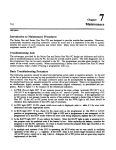
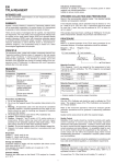
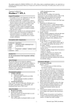
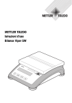
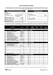
Chapter m 71 7 Maintenance Introduction to Maintenance Procedures The Series One and Series One Plus PCs are designed to provide trouble-free operation. However, occasionally situations requiring corrective action do occur and it is important to be able to quickly identify the source of such situations and correct them. Many times the need for corrective action originates outside of the PC. Troubleshooting Aids .- The advantages provided by the Series One and Series One Plus PC design are indicators and built-in aids to troubleshooting not only the PC, but also the overall control system. The main diagnostic tool is the programmer that can be easily attached to the PC. The programmer provides great insight to the status of the overall control system. When troubleshooting a Series One or Series One Plus PC based control system, make a habit of having a programmer with you. Basic Troubleshooting Procedure The following questions should be asked and appropriate action taken to negative answers. At the end of the list of questions are step by step procedures to be followed to replace various modules in a Series One or Series One Plus PC. All major corrective action can be accomplished by replacing modules. No special hand tools are required except for a screw driver and voltmeter. There is no requirement for an oscilloscope, highly accurate voltage measurements (digital voltmeters), or specialized test programs. Refer to figure 7.1 for location of the rckmnced indicators. 1. Is PWR (Power) light ON? If not, measure power at the input voltage terminals (98-126 V ac or 195-252 V 8~ as appropriate) on racks using an AC source of power. For racks rquiring a DC power source, measure the DC voltage between the +24 and 0 V terminals. If the appropriate AC or DC power is not present, locate the source of the problem external to Series One or Series One Plus PC. If the AC or DC power levels are correct but the PWR light is off, fuses should be checked, then rcpl acement of the CPU rack if necessary. 2 . Is CPU light OFF? If ON, check which error code is displayed, r&r to table 4.1 for error code . action. d&nitions and take F 3 . IS RUN light ON? If not, check for the cause such as the programmer in the PRG or LOAD position or programming errors. If RUN light is OFF and a pgrammcr is not mnnwtcd, or the propammcrinintkRUNmodcwith ou t an error code being displayed, rcp&0c the CPU module. 4 Is the BAT’I’ light ON? If yes, replace the battery. Sin= the BATI’ light 5s only a warning level, the program my be unaltered even if the batt#y is low. Afk replacing the brm#y, examine the programoYtcstthOc apcrati01~ Ifafaultislocatedreloadtheprogramfnrmtapencordedattht completion of initial system programming. l 5. Inmultiple~syaemsifthecPUisoperating,~RuNrelaycanbe~~~fulin~wifying operation of the other pz.;a* supplies. If the RUN relay is not closed @igh resistance) check the AC or DC poww impply as in step 1 above. Adequate AC or DC power and 8n open relay requires replacement of the rack. m 72 Maintenance GmMo842 a40288 Figure 7-l. Troubleshooting Indicators General Troublesbooting Procedure Additional procedures depend upon knowledge of the are more general in nature and should be modified application. There 8l[r$no better troubleshooting tools the programmer and place it in the RUN mode, then logic installed by the user. ‘I3e following stqx or adjusted as necessary to meet your specific than common sense and experience. First plug in follow these steps: 1. If the Series One or Series One Plus PC has stopped with some outputs energized or basically in mid-stream, locate the signal (input, timer, coil, sequencer, etc.) that should cause the next operation to occur, The programmer will display ON or OFF condition of that signal. 2 . If the signal is an input, compare the programmer state with the LED on the input module. If they are Merent, replace the input module. If multiple modules in an expansion rack appear to require replacement, ver@ the I/O cable and its connection before replacing any modules. 3 . If input state and LED on the input module agree, compare the LED status and the input device (pushbutton, limit switch, etc.). If they are different, measure the voltage at the input module (refer to Chapter 6 for typical I/O wiring). If the voltage indicates a problem, replace the I/O device, field wiring, or power source; otbwisc; +ace the input module. 4 . Ifthesignalisacoilwindtoafield~vice,campareitsmatustothe LEDontheoutputmodule. If they arc difSercnt, verify the source of field power to ensure exitation voltage is available. If field power is not present, examine the power source and its wiring. If tbc pqxr Geld power is available, but the status is wrong af the W module’s output fenninal, repke tht output module or vcri@thattherackisprovidingthcproperpowcrtotbemodule. 5. IfthesignslisaooilandeitherthereisM,outputmoduleortheou~ut is~~8Hhecoilstate, examinethelogicdrivingtheoutputwithtbeprognrmmerandahardcopyoftheprogram. proceeding fhm tight towards le& locate first contact that is not passing power that is otherwise . availabletoitfkomW left. Troubleshootthatsignalperstcps2and 3aboveifitisan input, or 4 4 5 if it is a coil. EnSVnr:&.S Master Control Relays arc not tikting operation of the logic. m 73 Maintenance 6. If the signal is a timer that has stopped at a value below 9999, other &MIIoooo, replace the CPU module. 7. If the signal is the control over a counter, examine the logic controlling count signal. Follow steps 2 through S above. the reset first and then the Replacement of Components The following proceduzs provide details on proctdms Series One or Series One Plus PC system. to be followed when replacing components of a Replacing a Rack 1. Tum OFF power and reTnove the programmer (if installed). 2 . Remove the plastic cover and disconnect power wiring from the terminal board on the lower right side of the rack. .- 3 . Remove all I/O modules. YO wiring does not have to be disturbed if setice during the original installation. loop was provided of each module in the rack for proper Note the position reinstallation. 4 . Remove CPU module (if installed) and any filler modules. Place them aside in a safe location for later reinstallaxion. S. Remove bottom two bolts holding the rack in place. Loosen but do not remove the top bolts. 6 . Slide base unit up and then pull forward to clear the top mounting bolts. Set the rack aside. 7 . Reinstall the new rack onto the top mounting bolts. 8 . Insert bottom bolts and tighten all four mounting bolts. 9 . Install the m Placinga module modules in the same slots from which they were removed. in the wrong slot m cause incorrect and dangerous operation of the control system. 10. Install the CPU and any filler modules that were removed. 11. Reconnect power wiring to the terminals on the right side of the rack. Reinstall the plastic cover over the power terminals. check aperation of the entire 12* Verify proper power wiring and then tum power ON. Carely ~~toenrmrethatall~modulesartinthcirpraperlocationsand~programisnotaltertd. Replacing a CPU Module 1 Turn OFF power and move l 2 . S+=z the programmer (if installed). the CPU nmdule ait the front, top and bottom to rtleast securing t&s. 3 Pull the module tight l 4 a If PROM mmv out dram its slot. had been installed in the CPU, szmove the PROM and &tall & h &e new CPU. Maintenance GEL90842 5 . Insert the new CPU module by f’irstaligning the printed circuit boards into the bottom board guide. 6 Rotate the module upwards slightly to engage the top board guide. l 7 . Push the CPU module into the rack until both tabs snap into place. 8 . Reinstall the programmer and reapply power. 9 . Reload the program from tape recorded after initial system programming. Check operation of entire system. Replacing l/O Modules 1. Tum OFF power from both the rack and the UO system. 2 . Remove the plastic cover from over the temkals on the I/O module to be replaced. wiring on the defective module needs to be removed. *- Only field 3 . Disconnect field wiring from I/O teminals, detach the removable connector, or remove the connector to the I/O Interface cable, as applicable according to the type of module. Lzibel each wire or nott installed wire marking for future reconnection. 4 . Squeezethe I/O module at the fkont, top and bottom to release securing tabs. 5 . Pull the I/O module straight out. 6 . Insert the new I/O module, aligning printed circuit boards fint into the bottom board guide. 7 l Rotate the module slightly upwards to engage the top board guide. 8 . Push the module into the rack until both tabs snap into place. 9. Reconnectall field wiring, replace the removable connector board or n=pplace the connector, then xcplace the plastic cover. 10. Reapply power to the CPU, then to the I/O system. Check operation of the system, especially the UO module that was replaced. Replacing the Battery If the CMOS memory back-up battery requires replacement, s&r to the following procedures. Figure 7.2 shows the battery location on the CPU, location of the battery connector and the bmry tie-down =4= 75 Maintenance m a40289 Figure 7-2. Battery Location and Connection .- 1. Remove the CPU following the previous instructions. 2 . Cut the plastic tie down straps that secure the battery to the board. 3 Disconnect the battery. There is sufficient capacitance in the system to retain the CMOS memory contents even without the battery for about 20 minutes. l I WARNING I The lithium battery sbould be handled with care. DO NOT discard tbe battery iu fire. DO NOT attempt to recharge the battery. DO NOT short the battery. If these precautions are not followed, the battery may burst, bum or release hazardous materials. 4 . Connect the new battery (catalog no. IC610ACC150) and place it in its proper position on the printed circuit board. 5 . Secure with new tie downs or insulated wire. 6 . Reinstall the CPU module. 7 . Verify that the BATI’ light is OFF. If necessary, reload the CPU from a tape m&e afkr initial system pro gramming. Then, check operation of the entire system. 8 . Iftht~oprintedcircuitboardsthatmakeupthtcPUarcseparated,ensuItthattheyare ~~onnccted, installed in a rack, and power4 up. Otherwise, logic may lock into a high current drainmodeandp remauely drain the battezy. Adding Memory The following procedure should be followed when adding memory to a Series One 0~ Series One Plus PC. Either CMOS IUiM memory can be added to increase mory capacity fnnn 700 words to 1724 words or non-volatile PROM memory can be installed that contaim a pmgmm previously entered into the PROM. 76 Maintenance I, a40290 Figure T3. Location of Extra Memory Socket .- 1. Before installing additional memory, it is recommended that any prow currently in memory be horded on tape. If this is not done, the program will be lost after memory is added and a Clear All Memory operation is performed. 2 . Remove the CPU following previous instructions. 3 . hate spare memory socket at the rear of the larger printed circuit board in the CPU. 4 . Obtain the required memory IC either type 6116LP for Series One or 6264LP-15 for a Series One Plus, 2K x 8 bit CMOS RAM: (or equivalent). If adding PROM memory, obtain an Intel type 2732A-2 for Series One or a 27256-25 for a Series One Plus (or equivalent PROMS). Ensure that the CMOS RAM or PROM is correct for your PC. When handling CMOS memory 10, aiways handle by the case and not leads. Static electricity on leads can damage internal circuits, This damage may not be apparent for several days or weeks of operation. 5 . Orient the IC so that the notch at one end matches the notch in the memory socket. 6 . For clearance when insMing memory ICs, it may be necessary to lift the smaller printed circuit board l/8” (3mm). Do not separate the boards. After the mcmoxy IC is instab& reseat the smaller ‘board, 1 . Insert the IC intothe socket casefblly and evenly so as not to bend any leads. Visually inspect to cnsurethatallleadsateinplaceandthenpushdowntofirmlyscattheIC. Ifa6assary,rcadjustthe jumpers and/or switch 2 as shown in table 3.2. 8 . IfthetwoprintedcircuitboardsthatmakeuptheCPUarescparated ensurethattheyare reconnect& installed in a base unit, and powed up. Othcwisc, logic may lock into a high cuxzent &ainmodeanciprcuWwelydrain thebaitte~. 9 . Reinstall the CPU module following pwious instructions. Maintenance 10. Power-up the CPU, place the mode switch in the PRG position and perform a Clear All Memory operation (CLRSHF348DE~. The entire memory will now be entirely clear of data. Any pqram previously recorded on tape can now be loaded into the CPU from tqe or a new program can be entered. Spare Parts and Components To support the Series One or Series One Plus PC, an Accessory Kit is available (ICalOACC120). This kit includes commonly needed components that may get damaged or lost in the normal course of operation. For a complete list of accessories for the Series One Family of programmable controllers, refer to GEP-762. Rather than axtempting to place ord?rs for plastic covers, fuses, audio cables, screws, etc., this kit can be ordered and provides sufficient material to support 3-5 CPUs depending upon their I/O count. Included in the kit arxzthe following items: I ITEM ITEM QW@ Cable, Frogrammer to Tape Rccder Cable, Programmer to Peripheral 1 1 cover,cPucoM!eaor 1 Cover (large), DCU, PROM Writer, Rinter Interface Cover (small), DCXJ, PROM Writer, Printer Interface Cover, I/O Termid Cover, Power Supply Terminal Cover, Rack Dust Fuses, 1A SB Fuses, 2A SB 2 Fuses, 2A SB (Spiral Ekmcnt) Fuses, 3A FB Fuses,3A SB Rises, 4A SB Fuses, SA FB Fuses, 1OA SB Key, Hand-Held Programmer Screws, PH (M3x5) Screws, PH @43x7) Screws, PH @43x16) Spacer 1 4 2 1 5 3 QW* 3 5 5 3 3 5 1 10 10 10 3 When supporting a Series One or Series One Plus installation, it is recommended that spare modules be available on site. These are in addition to the Accessory Kit previously discussed. As a guide to your requirements, the following percentages are presented. As a minimum, one each of all modules is recommended. Depending upon a number of application related conditions (location, average weekly hours of qxration, cost of downtime, etc.) more units may be justified. I Base with Power Sqply CPLJS Inpat b!bdn@ outplt ~~ Rw==- (=b Cd cables Puipbual Devias type) type) 96 SPARES 15 15 10 1s 10 10 10 Maintenance GEIC-90842 a40022 Figure 74. Accessory Kit for Series One/One Plus Fuse List Table 7.1 is a list of fuses used in Series One I/O modules. Table 7-l. I/O Module Fuse List I/O MODULE CATALOG NUMBER CURRENT RATING (AMPS) CIRCUIT CONNECTION QU- TYPE OF FUSE IC61OMDL103 ICdlOMDLlO4 IC61OMDLllS 3 Amps 10 Amps 3 Amps 1 1 2 sokieIed -clip fuseclips picofb miniame sb rninhm sb IC61OMDLlSl IC61OMDL153 lC61OMDLl54 3 Amps 5 Amps .5 Amps 2 4 4 sokkzed filseclips filscclips pica SIiniahlrefb miniahuefb IC61OMDL155 IC6lOMDL156 IC6lOMDL157 3 Amps 3 Amps 3Amps 5 Amps 5-s 3Amps 10 Amps 5Amps 2 Amps 5 Amps 2 4 2 sol&d Soldered pi=) pim SddCred tic0 2 2 4 2 1 2 sol&led soldered pi= pico!b lxkimrefb miniature sb nkiame sb IC6lOMDL158 IC61OMDLl75 IC61OMDL176 Ic61oMDLl8o IC61OMDLl81 mslOMDLl82 IC61OhJDLl85 2 f=clips fuscclips fuse clip fiase dip sohked NW Chapter 810 8 Applications GEK-90842 Application 1 - One-Shots This application is particularly useful when applied with a Series One PC, since with a Series One Plus PC, a one-shot can be programmed simply by entering the key sequence SET OUT RESET. In many applications, a signal is required that is valid for a very short time period. These signals are called one-shots and are generated by transitions (OFF to ON, or ON to 0%) of a control signal. They are valid for exactly one scan, which is the shortest signal available within the Series One and Series One Plus PCs. Timing for typical One-Shots is as follows: Figure 8-l. Typical OnemSbotTiming In this example, input 01 is the control signal and coil 160 the resulting one shot. one-shots IAgic for these is shown below. pc-$1m-0041 I I Fiie 02 2”” 8-2. Typicd OneSbot Logic 9:: m 82 Appkations % CEIL-90842 Application 2 - Flip Flop This logic rwerses states (ON/OFF/ON/OFF, etc.) each time a control signal is energizd. In this example, the Flip/Flop changes state on the OFF to ON transition of the control signal. A typical timing diagram is as follows: pc-sl-83-0042 )9vI -II -1 *1 *2 13 Figure 8-3. Typical Flip-FIop Timing Diagram In the following typical logic, input 01 is the control signal and output 20 is the flip/flop. pc-sl-83-0043 01 161 160 01 161 160 20 162 Figure 84. Typical FliplFlop Logic 83D Applications GEK-90842 Application 3 - Event/Time Drum Many control requirements can be defined as a sequence of established sttttcs for each output. The decision to shift from one step to another can be based upon time or specific input states. To illustrate this concept, the following 6 step example is provided. The control on inatig the step is a confirmation of both events (for example, input 11) and a time value (for example, timer 601). step , Input Time 20 21 22 23 24 25 26 27 4 10 11 12 13 5 14 T600 T601 T602 T603 T604 0 0 0 1 1 1 0 1 1 0 1 0 1 1 1 0 0 1 0 1 1 1 0 0 1 1 0 1 0 1 1 0 1 1 1 0 1 0 0 1 Number 1 2 3 4 Each step can have Merent output states and more or less control can be implemented requires. The ladder diagram required to implement this function is as follows: Fiie 8-5. EvenVI’ime Drum Logic as the application / Applications 8-4 GEK-90842 STEPNUMBERI fx-sl -03-0047 TMR600 06 06 STR TMR *-- STEPNUMBER 2 07 t: STEP NUMBER 3 342 0 341 601 7 .o STR TMR mm- l-W602 08 8 STR TMR -a- . 342 602 1 .o STEPNUWER4 TMR603 343 09 ---ISTEP NUMBER TMR604 ----+I ADVANCE I t TMRGO 1 010 STR TMR -am 344 604 1 .o 0 STR OR OR OR OR OUT TMR600 TMRGO 1 TMR602 TMR603 TMR604 345 STR STR CNT w-m 345 17 605 5 DRUM 345 v I t TMR602 343 603 1 .o 5 344 TMRGOO STR TMR w-a 11 , 1 I TMR603 t t TMR604 11 SEQUENCER 345 1I 17 -----+I qCNT 4 605 I 012 Figure 84. Event/Time Drum Logic (Continued) Applications 0 GE?wo842 DEWCE NUMBER 1 605 1 “1 013 /rJ--- STR OR ET 605 4 605 5 20 5 DR(K=ENUMBER2 605 605 605 1 3 4 21 4 I DEVICE NUMBER 3 015 STR 605 OR 605 OR 605 iii 605 OUT 016 605 OR 605 Figure 84. Event/Time Drum Logic (Continued) 3 4 5. 22 sTR iiiiT 1 3 5 23 Appliu~tions GEwo842 pc-~1-83-0049 605 DEvcE NUMBER 5 24 0‘7 STR 605 OR 606 OR 605 -- &T 31 1 2 5 24 11 5 DEVCENUWER6 0l8 STR -* 605 -OUT 19 04 605 DEVICE NUMBER 7 26 1 005 019 NUMBER 8 1 3 5 25 605 OR 605 OUT DMCE 605 STR -e OR OR 3 605 605 605 605 1 3 4 5 26 27 a 0 STR 605 OR 605 GiiT Figure S-5. Event/Time Drum Logic (Continued) 2 5 27 Applications GEILW842 Application 4 - Cascaded Counters If an application requires a counter with presets greater than 9999, multiple cuunkrs c8111be assigned to that function. Two counters can record values up to 99,999,999 and three up to 999,999,999,!399 etc. Additional logic is incorporated to generate a reset signal at 10,000 counts instead of the normal 9999. The following logic uses two counters to record up to 99,999,599 events. Counter 601 records the low order values (thousands, hundreds, tens, and units) and counter 602 the high order values (tens of millions, millions, hundreds of thousands, tens of thousands). pc-sl -83-0050 cAscADEDcouNlERs WE SHOT mm 01 01 STR AND NOT OUT Do 340 341 t+ 02 02 D0- ST-R OUT I+ =Sf COUNTER bJ CHAti (O-1D()OO) 03 I AND NOT SfR CNT OR CNT 341 342 601 01 601 9999 EXTENDS CNT 601 BY ONE COUNT 342 341 601 342 “is”‘S 0+ STR SEcohm COUNTER IN CHAIN (1 o,ooo-99,990,ooo) 342 602 &502 0 it = , 01 I t Figure b l 8-6. Sample Cascaded 342 602 01 602 9999 88 Applications m GEL90842 Application 5 - Coil 374, Power-Up One-Shot In industry, power loss to machines and process equipment is a fkquent event. When such an event occurs it creates havoc with automatically controlled equipment and processes. The moment power retums it may be desirable to place the machine or process in a “hold” state until verifktion or critical limits, position of moving parts, and support quipment interfaces a conkned to be correct by authori& personnel. Description of Operation The Series One and Series One Plus PCs have a special function reference (internal coil 374) that provides a pulse during the first scan only after powering up the CPU (or going from program to run mode). Using this pulse in the ladder logic, as shown below, will place the machine or process in the desired hold state. .- The instant power returns to an automatic machine or process, certain phases (for instance, activating a cylinder, starting a motor etc.) of the automatic cycle need to be inhibited until a correct state is determined allowing the continuation of the cycle. The following program scheme will inhibit those critical outputs from activating field devices until a reset pushbutton is depressed, thereby, releasing all inhibited outputs and allowing the cycle to continue. 0I 02 IO ttHt 0 I2 3 04 20 340 kt, 200 - CYLINDER EXTfnD A 130 340 IY 250 RUN CDNlv:ovoe Figure 8m7. Typical Machine or Process Power4Jp Inhibit Logic Tht pro&ram logic in the above fim is an example you csn use to inhibit certain phases of a cycle. In this example, when power rctums to the process, 374 will be on during the fixst scan of the CPU, latching coil 340 on. ‘Ihe referenced NC contact of coil 340 is plaid in series with the logic that actuates output coils 200 and 250. Even if the program logic is calling far coils 200 and 250 to turn on, theywillnotuntil34Oisunl8&& The mly way to unlatch 340 is to &press tbc reset pushbutton (MO), allowing outputs 200 and 250 to be tumed on. 890 Applications Application 6 - Coil 375, 1OHz Clock The Series One and Series One Plus PCs have a special function refkrencc that cantinuously provides a pulse every tenth of a second. The following t\wo examples use the function of this reference (10 Hz Internal Coil 375) to create a cumulative timer and a time of day clock. Example 1: - Cumulative Timer In this example, when reference 01 is on, time (in tenths of a second) would be accumulated by counter 600. If the time to be measured is anticipated to be larger than 999.9 seconds, cascading another counter will increase the range to 9,999,999.9 seconds. This technique allows you to meas= the duration of an intermittent event that would otherwise reset the standard timer when changing state. STR AND STR CNT 01 375 02 600 9999 FTligure8-8. Cumulative Timer Example 2: - Time of Day CIock In this example, the 1OHZ clock (Internal Coil 375) is used to program a time of day clock with reset capabilities. This is a 24-hour time clock, with the time format being xX:W, where Xx = hours (O-23) and W = minutes (O-59). The 1OHZ clock providts the 0.1 second pulse to counter 603 which in turn produoes one pulse every second. The mminin gthmecounters,600,601and602kuptrackof seconds, minutes and hours that have elapsed. If power goes off and the clock needs rcsetig, the combined use of a 3 position switch and a pushbutton, as shown in Figure 8.10, will allow you to set the comet time. The lower portion of Figure 8.10 is the ladder logic which ~sets the clock. An VO Simulator module, IC61OMDLl24, could also be used and programmed to reset the clock). a40509 02 02 603 -ICUT SECONDS I so -i CUT m CUT603 ml6Q STR CWT600 cwr 600 co E CM1600 03 5rR CUT 600 OF?161 ND MDT I60 STR CWT 601 CUT 601 60 ST'R CNT 602 kc 24 CNT 602 24 Figure 8-9. Sample 24 Hour Time Clock Logic Applications 8-11 a40557 THREE POSITION - SELECTOR SWITCH PWWTTON *DENOTES Ix)REFERENCE 05 LADDER LOGIC 01 f604 ' 2HZ CLOCK 1604 05 STR 01 AnO NOT T604 Figure 8-10. Time Clock Resetting To met the time,use the following procedure. 1. Select hours, minutes or seconds with the 3 position selector switch. 2. Monitor the appropriate counter. CNT 600: CNT 601: CNT 602: Keystroke 3.Depressthechan Seconds Minutes Hours sequence is SHF, 6xX, MON ge btt u on until the pmper value (time) is displayed on the programmer. 8-12 Applications GEK-w2 Application 7 - Start/Stop Circuit A simple but informative application for the Fast Response module is the Start/Stop circuit. In this example, Output 4 is in the Fast Response mode and is controlled by Inputs 0 and NO. 1. The timing diagram shows worst case response times. I X4lNFASfRESPWSEICIK)(N Figure 8-11. Fast Response Start/Stop Logic I/O REFERENCE 00 01 04 05 200 D-ON Enablcoutput,X4ihhstrtsponsemode Disable output X4 in fhst Itspotse mode ou~X4tiedtofielddevi~beingco~lled Mode z&ct for aaput x4 DISABLED: msnualmode ENABLED: fhstqxmscmodc DummycaucttoputoutputX4infbstrcsponscmode pc-sl -84-0019 Figure 8d2. Worst Case Thing Diagram . Applications 843 Application 8 - High Speed Counter Applications Threegeneral types of application examples will be covered within &is applica2ion. 1. Programmable 2. Cut CAM Switch to Length 3. Measurement of length In the development of these applications the following system configuration will be used. pc-sl -04-0010 - 0 l/o vo vo CW SERES ONE POHIfR SUPPLY CA Fiiiiiire843. Application System Apptications 8-14 Programma ble Cam Switch The basic concept behind a CAhd switch is to enable/disable certain devices at various points in the cycle of a machine. Using one or more high speed counters this type of control can easily be implemented. The following example illustrates this, cycling the high speed coulltcf’s two outputs at difkent preset values. The timing diagram below shows the output logic, with the user program necessaq to implement this logic shown on the following pages. This example assumes that the encoder is resetting the counter once per revolution, and that the machine will not travel f&m one transition point to the next in less than twice the scan time. a40023 150 CURRENT COUNT 0 PROCESS STAGE 1 FIRST [SECOND 1 THIRD IFOURTH 1 FlFTH 1 SHIFT REGISTER STAGE 1 400 OUTPUT NO.1 OUTPUT NO.2 Figure 8-14. Programmable 50 1 401 250 I 402 1 403 325 1 404 360 1 I I ] I CAM Switch Logic Timiq Diagram a40893 Figure 8-15. Programmable CAM Switch Applications 8-15 0 6 cit I 165 00 01 07 I 162 1 SR 162 Figure 8-15 Programmable CAM Switch (Continued) SHlF7 REGISTER THAT WERMINES STAGE OF SEOUENCER 846 Applications GEK-90842 a40893 400 08 i +Ht 162 . , SO Wl’PUT NO 1 NOT INVERTED OUTPUT No 1 IN COUNTER MODE OUTPUT NO 2 DISABLED ~TPUT 64 0 9 \ NO. 2 M MANUAL MODE . SECONDSTAGE ( --i 1 CURRENT COUNT < PRESET MTWUY CNflOl 150 4 i 100 S OuTptn NO. I INVERTED 103 s OUTPUT NO. 2 IN COUNTER MODE f Figure 8-15 Programmable CAM Switch (Continued) Applications GE&=42 With this type of control application the object is to generate a pulse output every X numkr of counts. In cut to length applications X rcpments the length of material to be cut in pulses from the encoder. The following example pulses output No. 1 of the High Speed Counter once evczy 100 counts. The figurebelow shows the logic diagram for output No. 1, while the next figure contains the wiring diagram for this type of application, followed by the associated ladder logic. a40894 OUTPUT NO. 1 CURRENT COUNT 0 100 200 300 400... Figure 846. Output No. 1 Logic Diagram WSHSPEEDCOUNTER MOOULE 8 USER LOAD OUTPUTNO 1 f A+ 5-24VDC USER SUPPLIED Y - RESET COUNTER DECREMENT COWTER DECREMENT PULSE -1 COUNTER +lZvDc f 1O’l USER SlJPf’UED Figure 8-17. Wiring Diagram Applications GEK-90842 a40005 ONE SHOTTO WITE PRESETTOHsc OUTPU?NO.1IN COUNTER MODEOf OPfRATION Figure 8-18. Cut to Length Program Measuring a Random Length .- In measuring the length of moving objects, the leading and trailing edge of the object enables and disables the counter which is tied to the encoder. At this point the accumulate value of the counter repments the length of the object. Unfortunately the accumulate value of the High Speed Counter cannot be moved into the user logic of a Series One or Series One Plus PC. Thus an objects length can only be measured relative (> = <) to a preset value in the counter. Through the use of a shift register and multiple presets, the length can be approximated to within two successive presets. To determine the accuracy a moving objects length can be measured. Three parameters must be considered: 1. Velocity of Object (pulses/second) 2. Resolution of Encoder (inches/pulse) 3. Scan time of the Series One or Series One Plus CPU (seconds) These three factors combine in the following manner to determine the accuracy of measurement. Accuracy of Measurement = R INCH V PULSE 1.1s~ (sex) PLJLSE SEC Applications 849 GEwo842 Sample Calculation Given: 1. 0.1 inches/pulse 2. 60 RPM, assume 1 pulse/degree = 360 pulses/second 3. Scan time 20 msec PULSE SEC The user logic as shown would implement I/O Definition: Ill - Photoelectric this type of measmment giving a resolution of 10 counts. cell which enables counter 110 - Manual Reset/initialize a40895 01 02 03 04 0s F&we 8-19. Measuring a Random Appikations 8-20 a40895 0a 0 7 0 0 0a 010 0 11 0 12 n 0 0 la CWlW 00 on Fiire 101 10 wrrmunkV*uIETOmc 8-19 Measuring a Random Length(Continued) a40895 Fiiiiiire 8-19 Mtssuring a Random Length(Continued) Applications 8-21 GEK-90842 a40895 0 21 0 22 022 Figure 849 Measuring a Random Length(Continued) a40895 Applications 8-22 Application 9 - Typical Shift Registers When applying controls to a conveyor system or indexing machine, consideration must be given to the object being assembled, since it invariably has discrete information (pass, fail, etc.) ~sociated with it. Each time that the object is advanced in the assembly process, its discrete information must follow it. The shift rqister fiuxztion provides this control within the Series One and Series One Plus PCs. Referring Number the pass and one to the following example, the objects undergo a mechanical and visual inqxction at stations 1 and 3. If either inspection fails, the object is rejected at station Number 5. In order to track or fail status of each object, two shift registers are required, one for the mechanical inspection for the visual inspection. pc-s l-83-0044 Fire 8-20. Shift Register Example In this example, I/O and shift register references are assigned as follows: OUTPUTS INPUTS 00 Advance belt, shift 01 lttkhmiealinspection O-PI-fail 02 visual isa!gmim Q-P03 II-fail ReaeebiftRcgista signal 20 Reject Arm o-off l-On Applications Shift 8.23 Register References in mechanical inspection shift register. 400 First Mixcnce 401 Secondreference in medumical 402 Third 403 Fourth reference in mechanical inpaion 410 First Itaaxe 411 second rtfezace inspection shift register. reference in mechanical impection shift register. shift register in visual inspection shift rqiskr. in visual hspection shift register. Typical logic using these refemxes is shown in the following ladder diagram. pc-s f-83-0045 00 161 1eo 00 161 01 160 2 403 Figure 8-21. Typical Shift Register Logic Appendix A Related Documentation Introduction Several manuals are available that complement this manual. These manuals provide information rqukd to fully implement certain featwrts and options available for use witi a Series One or One Plus programmable controller system. A basic description of the content of these manuals is provided in this apPendix. The following manuals are available and along with this manual, constitute a complete set of documentation for a Series One or Series One Plus PC system. _- GEK-90477 GEIWOS07 GEK-90825 GEK-90846 GEK-96632 GFK-0075 Series OneData Communications Manual Remote IjO User’s Manual Series Six PC I/O Link Local Module User’s Manual Portable Programmer User’s manual Logicmaster 1 Programmer Documentor Manual Logicmaster 1 Family Pro gramming and Documentation Software GEK-90477 Series One/Three Data Communications Manual This manual provides information necessary to implement a serial communications link between a Series Six or Series Six Plus programmable controller (PC) or host computer and a Series One, Series One Plus, Series One Junior, or Series Three PC. You should become familiar with the operation of the Series One, Series One Plus, Series One Junior, or Series Three PC (depending on your application) before reading this manual. Also, if a Series Six or Series Six Plus PC is to be included in your communications link, you may wish to refer to the Series Six Data Communications Manual, GEK-25364, for relevant infoxmation. Chapter 1, Introduction, describes the capabilities of the Data Communications Unit (DCU) and the Data Communi cations Module (DCM) and possible system configurations of Series One, Series One Plus, Series Ont Junior, and Series Thret PCs with a Series Six or Series Six Plus PC or host computer. Chapter 2, Installation and Operation of the Data Communications Unit for the Series One, Series One Plus, and Series One Junior PCs, bcribes interfaces and the installation of the DCU. the operation of the Data Communication Unit’s user Chapter 3, In&al&ion d operation of the Data Communications Module for the Series Three PC, dcscribts the operaticwlt of tk Data Communication Module’s user interfaces and the installation of the DCM. Chapter 4, Ektrical Interface Circuits, provides the information needed to constnzt c0nneCttheDCUorDCMto~rdtviccs. cables to Chapter 5, Communications Examples, explains how to build the Series Six ladder diagram to initiate corrnnunications between a Series Six or Series Six Plus PC md a Series One, Series oht Plus, Series One Junior, or Series Thp#: PC. Chpter 6, Serial Interface Pro-l, provides complete &kcncc inform&on on DCU and DCM serial interface pc01 and thing to allow the user to write a serial communications driver for a host computer or micimpmcessor. Am2 Related Documentation GEK-90507 Remote I/O User’s Manual This manual provides information needed to implement a Remote &/Osystem llrcinp the I/O of Series One and Series Three PCs. Chapter 1, Introduction to Remote I/O, is a general description of the Series Three PCs. capabilities of Chapter 2, Installation and wiring of the Ii0 Link modules, installation, wiring, and fault detection. discxsscs the hardware used, Series One and Chapter 3, Configuring a Remote I/O system for the Series One PC, dcscrilxs how to design and implement a Series One Remote I/O system. Chapter 4, Configuring a Remote I/O system for the Series Three PC, describes how to design and implement a Series Three Remote I/O system. Chapter 5, Configuring Mixed Remote I/O systems,destibes how to design and implement a mixed (Series One and Series Threz) Remote I/O system. Chapter 6, Timing Considerations, explains how to determine the timing delays in the Remote UO SUUctLlX. Appendix A, Power Supply Loading, lists the power modules used in Series One and Series Three PCs. characteristics of the power supplies and Appendix B, Design Worksheets, contains handy worksheets for designing Remote I/O systems. GEK-90825 Series Six PC I/O Link Local Module User’s Manual This manual describes the link between the Series Six family of programmable controllers and the I/O structure for the Series One and Series Three programmable controllen. ‘&is link is established between the Series Six I/O Link Local module and the Series One family and Series Three I/O IArk Remote modules. chapter ~vervicw 1, co~eding the Series Six PC to the Series One or Series Three I/O system, is an of the system con&uration and operation. Chapter 2, Series Six PC I/O Link Iacal Module and Programming, ex@ains how to install and optfate the Merits six I/O Link Local module and how to pgram the Series Six CPU for &JOLink bcal operations. Chapter 3, Series One PC I/O Link Remote ModuI~xplains _ the installation and operation of the Chapter 4, Series ‘lluee PC I/O Link Remote Moduk,cxplains Series ‘I’bcc PC J/D I&k Remote module. the installatbn and cpration Series One PC I/O Link Remote module. of the Chapter 5, Cable Wii, describes cable wiring between the Series and~series~orseritsThretPCyOLinkRemottmodule. A, B, and C, provide application infoxmazion on sttting up an uwmple m usingthcI/ochainstanlsbytc. Appendices chin and GEK4O846PortabIe Programmer User’s Manual Tht purpost Of this manual is to providt tioRna¶ion on the functions and feahuts of the Portable RogrammerandtoiWnxttbeuserinbAling, programming, and impl~hg the Portable Related Documentation Programmer A-3 with the Series One programmable controller family and the Series Three pgrammable conuoller. This manual contains nine chapttrs and six appendices. locating required infozmation. Each chapter contains scctioIIs to aid the user in Chapter 1, Product Summary, presents a product overview and describes the operating modes. Chapter 2, Operation, explains the installation and operation of the portable Programmer. Chap&r 39 introduction to Programming, provides general information Chapter 4, Definition and Entry of Inst~~tiom,explains instruction on pmgramming. how to start a new program and contains the sets. Chapter 5, Edit Program, provides instructions for entering the Edit mode and editing functions. Chapter 6, Display Program, provides the user with the information for displaying a ladder logic program* *- Chaptei 7, On-Line Monitor/Change, covers the On-Line Monitor available for the Series One Plus and Series Three PCs. and On-Line Change functions Chapter 8, Communications, explains how programs may be stored on cassette tapes or transferred to the PCs. Chapter 9, Print, covers the print options and fitnctions. Appendix A, Series One PC Serial Interface Setup, covers tie Data Communicatioris Unit and the CPU serial cable. Appendix B, Series Three PC Serial Interface Setup,contains inforrnaxion needed for connecting Series Three PC with the Portable a Programmer. Appendix C, Port Definition, describes the CPU serial port and the printer port. Appendix D, Compatible Printers, contains the necessary information to implement and specifications for selection of compatible Appendix E, printers. Series One Plus PC Password, contains instnxtions for password operation. Appendix F, Portable Programmer Case, illustrates optional carrying case for the Portable Programmer. GEK-96662 Logicmaster 1 Programmer Documentor Manual This manual presents the information necessary to use the Workznasttr industrial computer with the bgicmastcr 1 a@kation sofbwarc to program a Series One PC. The i~Sormation cuntain& in this manual conesponds to version 02.01 oft& Logicmaster 1 Programming and -on Sofiware. Chapter 1, Introduction, hoduccs how to load and copy it. the wpabilitics of the Lugkmaster 1 softwazc and also explains Chapter & WOdcHUbSW OperotiOn US& LOgi-r 1 SOftWW+c@ains basic operation of the Wow industrial computer when using Logicmastu 1 sofkw8rc. Sections a included on the kybozud, display format, and kcyswitch positions fa the Wozkmastcrcomputer and Series One PC. Chapter 3, programming tbe kies he PC, explains how to enter pro-g One PC through the Edit Program function. logic for the Series A-4 Related Documentation 4, Advanced bogramming Functions, ex@iins how to annotate Series One programs and how to use the Teach function to make programming on the Wo&naster computer easier. chapter Chapter 5, Logicmaster 1 System Functions, explains how to use the match pad, print programs, upload and download pmgmms, and use the filing programs. Appendix A, Menu Tree for Logicmaster 1 Sofbvare, provides a map to the function keys throughout the hgicmaster 1 software. Appendix B, Port Characteristics and Wiring Diagrams, provides the information needed to connect the Workmaster computer to the Series One PC or peripherals such as an extemal disk drive or printer. GFK4075 Logicmaster 1 Family Programming and Documentation Software User’s Manual _- This manual provides the information necessary to use the Workmaster@ and Cimstar PM industrial computers with Logicmaster 1 Family application software to program the Series One Model E, Series One Plus, and Series One Plus 3.7K Programmable Controllers. The content of this manual is arranged similarly to GEK-96662, as described above. Appendix B Glossary of Terms Address - A series of numbers from 0 to 1723 in the Series One and Series One Plus Programmable Controllers, assigned to specific program memory locations and used to ;OLCCCSS those locations. AND - (Logical) A mathematical operation between bits, whereby all bits must be a 1 in order for the resulttobeal. AND - (Function) An operation that places two contacts or groups of contacts in series. Both control the resultant statLis. BCD (Binary Coded Decimal) - A 4-bit system in which individual decimal digits (0 through 9) a~ represented by 4-bit binary numerals; for example, the number 43 is represented by OlOO(4) 0011(3) in the BCD notion. _- Bit - The smallest unit of memory. Can be used to store only one piece of information having more than one state (for example, a one/zero, ON/OFF, good/bad, yes/ho, etc). Data that rquires more than two states (e.g. numerical values 000-999) will require multiple bits. Byte - A me asurement of memory, in the Series One and Series One Plus, equal to 8 bits. CMOS - Acronym for Complimentary Metal-Oxide Semiconductor. A rea&rite a battery to retain its content upon loss of power. memory that requires CPU (Central Processing Unit) - The central device or controller that interprets user instructions, makes decisions and executes the functions based on a stored program. This program specifies actions to be taken to all possible inputs. counter - A function within the PC that records events based upon the on/off -ition of a signal. A coil associated with the counter is energized at a user determined preset value. Field Devices - User supplied devices typically providing information to the PC (Inputs: pushbutton, limitswitches, relay contacts, etc.) or performing PC tasks (Outputs: motor starters, solenoids, indicator lights, etc.). Group - A series of eight consecutive references, such as I/O points, internal coils, etc. Inputs - A signal, typically ON or OFF, that provides information to the PC. Instruction - A word, usually an acronym, or group of words and numerals that are part of a program entered into user memory. I/O (Input/Output) - That portion of the PC to which field devices arc connwtcd. Isolates the CPU hm ehrkal noise. I/O Scan - A method by which the CPU monitors all inputs and controls all outputs within a prescribed time. K - An abbreviation for kilo or exactly 1024 in the world of computers. Usually r&ted to 1024 words of memory. Ladder Diagram - A representation of co-1 logic relay systems. The user programmed logic is expressed in relay equivalent symbology. Latch - A PC operation thawcauses a coil to stay on and remain on even if power or the input is removed. Referred to as a mmtive function. B20 Glossary of Terms Logic - A fixed set of responses (outputs) to various external conditions (inputs). Au possible situations for both synchronous and non-synchronous activity must be specified by the us~f. Also referred to as the program. Memory - a physical place to store Formation such as programs and/or data. Microsecond (II& - One millionth of a second. 1 x lO=6 or O.OOOOO1second. Milkcond (mu) - One thousandth of a second. 1 x lo,-3 or 0.001 second. Modules - A replaceable electronic subassembly usually plugged in and secured in place but easily removable in case of fault or system redesign. Noise - Undesirable electrical disturbances to normal signals generally of high frequency content. Non-Retentive Coil - A coil that will tum off when power i,s mnoved. Optical Isolation - Use of a solid state device to isolate the user input and output devices from internal circuitry of an UO module and the CPU. OR - (Lcgical) A mathematical operation between bits, whereby if any bit is a 1, the result will be a 1. OR - (Function) An operation that places two contacts or groups of contacts in parallel. Either contrh the resultant status. Outputs - A signal typically ON or OFF, originaxing from the PC w&h user supplied power thar controls external devices based upon commands from the CPU. PC or PLC - See Programmable Controller. Peripheral Equipment - Extemal tits ti c8n communicate with a PC; for example, cassette tape recorder, Printer Interface Unit or PROM Writer Unit. Preset - A numerical value specified in a function which establishes a limit for a counter or timer. A coil will energize when this value is cached. Program - A sequence of fknctions and/or instructions entered into a Programmable Controller to be executed by the CPU for the purpose of controlling a machine or process. Programmable Controller - A solid-state industrial control device which receives inputs fkom user supplied control devices such as switches and sensors, implements them in a precise pattern determined by ladder diagram based programs stored in the user memory, and provides outputs for control of user supplied devices such as relays and motor stators. Programmer - A device for entry, examination and alteration of the PC’s memory including logic and storage areas. PROM - Acronym for Programmable Read Only Memory. A type of memory that requires a special method of loading, but is retentive upon power loss. RAM - An acronym for Random Access Memory. A solid-~ memory ht &ws i&ivid~al bits to be stoti and acct~scd. This type of memory is volatile; that is, stow& &a is lost under no power conditions, therefore a battery backup is rqhd. Register - A group of wn~r~=t..k .‘::e rmxnory locations within a PC, used for storage of numerical data RetentiveCoil-AcoilthatwillI#nain in its last state, even though power has been removed. Glossary of Terms B3- GEK-90842 Rung - A sequence or grouping of PC functions and instructions that control one coil. One or more rungs form a ladder diagnun. technique of ex amining or solving all logic steps specified by the ppm repetitive or&r from the first step to the last. Scan - The in a sequential, Thumbwheel Switch - A rotating numeric switch which can be used for inputting numeric data to a PC. Unlatch - A PC function that causes an output previously turned on by a latch function to turn off no rnantf how briefiy the function is enabled. Word - A measurement of memory, in the Series One and Series One Plus, qud Write - To output or transfer dam from the PC to a peripheral unit. to 16 bits. GEL90842 Appendix C Series One Family of Programmable Controllers Compatibility Guide Ft!8tUR -~-~ p Points (maximum) ~=ory Memory, 700 words CMOS RAM d to 1724 words M-ofY* Memory, E”g;;” 37 words CMOS _- EPROM, non-vole v Bawy Back-Up ‘Cal San 0.5 K Program: T lmesl.0 K Ropm: 1.7 K Ropm: 3.7 K Pro-: htcmal Function6 Non-Retentive coils RetaWe Cails Function Coils S lme~untcrs ?““’ lhumbwfiecl htufacc Module rimcr/Gmnscr Setpint Unit Shift Registas Data Regiliters (12) l *UencerS gb Speed Counter 3uibh (2 KHZ) LK)Module (10 KHz) -I/DMOdUlCS mlog I/O Modules Ided MO&k6 ;notcI)o $0. of I/O in Remote System Basic Ladder hag. Daa opcrrriOll6 and Math W/Hand-Held Pqpmmer ?!F I lwRG100 IC61OPRG105 Kand-Held Prog Maant hanbly 1. 2. 3. 4. 5. 6. 7. 8. Modd E Junior 24 Basic Unit 50 w/Exp Unit %W/Eqaack 112 112 168 stantiard y= (1) no #amid y= (1) stan&Td stadard IlO b0 y= yes (2) yes 0 yes (2) Ye6 Y= Y= y= (2) Y= no Y= Yes y= (7) Y= y= (8) 96 no Y= Y= Y= Yy= (8) 96 DO 20 InSec 4omSec n/r n/a 160 96 59 5 20 (44igit) 2OmSec 4UmSec 65 mSec % 144 112 28 4 64 (4d@) Y= Ii0 ;:S 1% dep6 l==P IlO IJO 20 Q (1) (1~ =p) 64 Ye6 DO (4, 5, 6) yes (4.7) ye6 Ye6 yt6 (9) 26,4Oor72 Ye6 DO Y= Ye6 Yes Y= no (1~ step) 8mSec l2mStc 15 mStc 48 144 112 28 4 64 (qt) y= (3) y” (3) 128 rtep6 no 64 (loo0 rttp) Y= no Ph6 3.7K Plus 168 IlO 8mSec 12 mSec 15 mScc n/a 144 112 28 4 64 (rldigit) y= (3) y- (3) 128 rtep6 64 (16bit) 6ulooo rtep) y=s (2) Y= 8mSec 12 mStc 15 mSec 36 mSec 144 112 28 4 64 (4_dieit) y= (3) y- (3) B=PS 64 (l&bit) 64 (loo0 sttp) Series One Family of Programmable Controllers Compatibility Guide c2 m GEK-90842 Futllre Junior !+opmn with WokrAM One= ModdE Ph5 3.m Phu (1) Yes Yes ’ Ya Y= Yes Y= Y=s Ya Y= n/a Y= 130 b0 110 n/a IlO n/a no s/a no Cumputer or IBM Personal complta kpJlW&hXDPlXL *w== ZPU 1C61KPU101 (UL I&cd) 1C610cPu104 1C61ocIw105 IC61OCPUlO6 Available ‘assword Ihccticm Yno II0 b0 YM 130 no no I)0 Y- no Y= Y= Y= bCk6 (2x6) no Yes Ye6 Yes Y= s-dot, 1C61oCHs110 IC6lOCHSlOl (2) ycr(clrplIlsi=) y= Yes Yes Y- s-slot, IC61oCHsl11 (5) Yer(~~) y= Y- Y= Y- hla, IC6loCHs114 (3) y-mp-w y- Yes Y= Y- m-da, 1C6mCHs130 (2) y=mp--w y= Y= Yes Yes lbhx, IC610CHS134 (3) yetitjqunsid y= Y= Yf= Yes S-Jot, .- yes (4) y= (4) thl& Y=s Y- no no no unit, Yes Y- Y= Y= yes Rev C Yes Y= Yes Y= Yes Rev A & B yes Rev A & B yes Rev B yes Rev B Y- 19” F&k Mounting Bxackets ht4lfhlIIlti~CXl6 ZCMlOO htJi &IXUIlUKliCtiCXlS ZCM105 RS2321422 AdaptouUnit Peripbml printer yes (4 y= (4) p (4) xkvias Unit Imdacc yt6 Rev C PROM Writer unit yes Rev A & B yes Rev A Br B yes Rev B yes Rev B yes Rev C Tiitusetpoiatunit Ye* no Y= Y= Y- CwetteTape Ye6 included Y= Y= Y=s Y= YW Y- Yes Y- Recder Accwwry Kit 1. 2 3. 4. 5. 6. Futue -crlt bt@CE 115/23t) with this pm&la v U POW’CX m. RequireS2LSV&pQcllnr~. &cd with l~rlot rack uLIi* 115v~poovw-~y. Not expandable 5% to 9!5% (non_ ZWSYeUr 8tolOYem 1ls/230vac MVdC See~~cxl8fo?~unitoa&fordct8ils Series One Family of Programmable Controllers Compatibility Guide c3 m Table C-l. I/O Module Capability/Compatibility Guide Fature Judor OX&P Model E plus 3.m Input Moddes KZ61OMDLl.25 115 V IC, 8 circuits ~C61OMDLl27 23OVac,8Circuits C6lOhmL126 115VrIBda44circuits :C61oMDLlo1 24VdcSi&8Ci1cuits C6lOMDL107 ~VdcSinkLoad,16Circuits C61OMDLlO6 24 V dc Sirrk, 16 Circuits C6lOMDLlll 24 V r/df Source, 8 Cixuits C6lOMDL112 ZU V &ic Source, 16 Cimaits [C6lOMDL116 bd0 h UtyeS (1) ~c6lO$lLKs (UL I&cd) 115 V u hput, 6 &Wit6 Kz61OMDLl75 115/230V ac, 8 Cimaits DlOMDL176 119230vac~4Cjmaits c6lOMDLl51 %V&Sink,8Cimits IC61OMDL156 24VcicSi&16Circuits KZ6lOMDLl53 24Vdc2ASi&4Grcuits c6lOMDL154 24Vdc2ASinl&wcc,4Circtits E61OMDL155 24VdcSowcc,8Cimaits KXlOMDL158 24V&S-,16M E6lOMDL166 b!i%$%L* ut, 8 Circuits bhY 9 1 (UL I&ted) E6lOMDLl SCircuits &hY E61OMDLl T 2 16 Circuits WY r61OMDLl v 5 (UL Iisted) R&y 0utput, 8 Cimzits K6lOMDL103 wvdchpu~4h$4Out K!6lOMDL104 wvdcsinlr:h/Rlyou~4hs/4out 1C610n4DL115 FastRcspacI/Q4In/2out IcmMDLm uOSimdrror,8Ingpt~ 1CXWTCCJ100 Ic610 ==“*“-tw LlO5 TInIInm 1c610MDL110 %w=d-t= hterface 1. R#luirur5orl~dae~mrrk. ZObt~~hrttrfrncKoDer~ yes (1) Ye6 yes Y= yes y= (1) Yes yes YU yes y= (1) Yes yes Y” Y=s yes (1) Yes Y= Y- yes y= (1) Y=s yts Yes yes y= (1) Yes Yes Yes yes y- (1) Yes Y=S Yes yts yes (1) Y=S Yes Yes yes Yes Ye” Y- Yes y+s Y= yes ye6 (1) Yes Output ModuAes yes (1) Yes yes Y= yes y- (1) Y=S yts Y= Y- yes (1) Ye6 yes Y- yes y= (1) Yes yes YCS y= (1) Y=s yes Y= yes y= (1) Yes yes Yes ylts y= (1) Y=S yes Y= P yes (1) Yes yes Y= yes ya (1) Yes yes Y- yts y- (1) Yes yes Y= yts ya (1) Yes yes Y= yes ya (1) Ye6 ye6 Y= yes yt6 Yes rcLf y= (1) Yes special Modu)m ~ )RS ya (1) Ye6 ye6 Ya yes y= (1) ye6 F6 y” ye6 y= (1) rc6 Y= Y= yts Y= (1) yes yes Y= PC6 ya (1) no F (2) F@ 0) yt6 (2) (2) P@ ye6 II0 ye6 F6 DO ye6 F6 oerSetpointpnitunbeurtdin~SerierObCP1\1E~natbath. Y= m F6 (2) Series One Family of Programmable Controllers Compatibility Guide C-4 Table C-2. Summary of Programming References for Series One Family of Programmable Controllers Mtmory Valid Rderemts (Octal) Typt -Qorotftg se&s Oat Junior w Point6 %tOtAl 15 9 16 10 40 OCKKU6 Basic Unit Inputs BUiChitQEpUb IED Expansion unit Inputs I/o Expamion unit ouqms Exp8nsioIlRackI/o 017-027 030-047 058-061 03cw67 13@137 160 total 96 59 1 1 1 1 1 155 (m) 20 (4 digit) (1) 1 20 (loo0 =p) IlltCZdcoilS 14w77 3001372 373 374 375 376 377 Mb372 6cxM23 624 6oM23 NOII-RCtUHiVC Retmtive Set Retentive Cc& First Scan Reset 0.1 Seccmd clock Diuble Au outputs Back-Up Batmy Status Shift Register Timers and Counters High speed Counm stqueact= se&s OnilSuits IntemJ Coils Nan-Retaative 16@337 34a373 374 375 376 377 4tKu77 Mn-677 axM77 Retaaive Chih Initial React 0.1 Second Clock DimHe All outputs Back-Up Batmy Status shift Registers Timcr~tcr6 sequsales oat PI&W hCXdcoi36 Non-Retentive Rctaaive Coils Initial React 0.1 Sacoad Clock Disabk All autputs Back-Up Batmy Sums S@8lhIpOUCOih shiftRt*m Ti~~tcrs z* 112 total 144tmaI ” 112 28 1 1 1 1 128 #taps 64 (1) 64 (10 =pp) an157 uc>poinQ m poinm157 ant Model E ant Plus 3.7K 168 total 700-767 1-337 34@373 374 375 376 377 8 4#577 (2) Hs677 -577 (2) 144t0Ul 112 28 1 1 1 1 - 128 rtcgt 64 (1) a (lax) -1 64 (l&m) Series One Family of Programmable Controllers Compatibility Guide Table C-3. Programming Function Compatibility Guide S'TRSTRNOT AND ANDNOT 0 bR NOT Sw 3ST Yes Yes Y=S Y=S Y=S Yes Yes Y=S Y=S OUT SET OUT SET OUT RST OR SIR MCS. MCR YZ Yes Yes STRTMR Y=S Y=S Y=S Yes yes Y=S Yes Y=S Y=S Y=S yes Y=S STRNOTTMR ANDT!bm ANDNOTTMR ORTMR OR NOTTRM STRCNT STRNOTCN'T ANDCNT ANDNOTCNT OR CM OR NOTCNT SR Yes Y= Ye6 Y=S Yy% Yes Yes Y=S Ye6 Ye6 Y=S Yes Ye6 Y=S Y=S Y=s Y=S Yes YCS Y=S Y=S Y=S Y=S Ye' Ye6 Y=S Y=S Yes Ye6 Ye6 Ye6 yes Yes Yes Yes Y= Yes Y=S Y=S Yes Yes Y=S Yes Yes Ye= Y=S Yes Y= Y=S Y=S Ye6 YY= Y= 110 Y=S Y= Yes Yes Y= YY=S Y= YY= Y= Y= Y=S Y=S Y=s Yes Ye6 Y=S Y=S Y=S Y=S Y=S Y=s Y=S no no no no no II0 no no no no no no no no no no DO 00 no no no no no no no y=s YCS YYes Yes Y=S Y=s Y=s Yes Y= Yes Y= YYes Y- xhta opaaions DcrR D.STRl (Data Stem) D.STR2 Dam3 DaTR5 D.cwT(Dataout) IbOUT IbouT Dam-3 DaJT5 COMPARE ADD SUBTRACIMuLrnLY DIVIDE DaND(LogicdAND) D.OR (bgicdOR) INVERT BIN(BCDToBin BCD&BhG~o SM(FTLEFIDECODE ENCODE EXTERNAL B%=s) FAULT DLAGNOSIS n0 n0 no no no no b0 DO 110 no no no n0 no no no no IbO n0 no no no no no 110 II0 I10 n0 n0 no no no n0 n0 no no no no no no no no no no no no no nQ no no YfS Yes Y=S Y=S Y=S Y- YY=6 Y= F YYe6 yes Y=S F' F YF Y=6 yt* ye6 Y=S Yyes . Ya yes Y= Y= YW Y=S Y+s YY= Y= Y= Yes Y- YYY= Y=S Y= Y=S Yes Y= YYes Yes Y= ' C-6 Series One Family of Programmable Controllers Compatibility Guide GEK-90842 Table C-4. Examples of Valid System Configurations for I/O Points I/O Points Valid Configmtion and Ref- I/O PCmd Rack Type Mod& Type -KAACMt% Series One Junior 10509SJR100 1c6o9sJR102 Basic Unit 000- 016 1ao9sJR110 or7- 027 outputs- -15 9 Inputs 1c?5o9sJR120 Iao9sJR114 Ic609sJR124 Iao9sJR121 3 Junior Ic6o9sJR1oO 1ao9sJR102 1ao9sJR110 IC609SJR114 Inputs- 15 1c6O9sJR120 outps - 9 Suits 50 u TPKA.41931 t 1 One Basic Unit 000 - 016 017 - 027 I . Ic609sJR124 Ic6O9sJR121 1 , I ! . f 030 - 047 I/oExpsionunits I/O Expansion Inputs - 16 outputs - 10 1c6o9ExP110 IC609EXP120 Iao9Exl?l21 050 - 061 , c 7 . TpKAA0097 Series One Junior 10609sJR100,102 1c6o9sJR110, 114 1ao9sJR120, Ic6o9sJR121 124 Basic Unit Inputs-15 l / 000- 016 outplts-9 017- 027 =uo , t 64 + . 1 / 11 111 t I oneExpar!sicmRack 5 : 8 ! or 1041a Rack114 1~1ocHs110, 1a1ocHs130, 134 (3) (1) 80Point l&Paint 1c61ocHs120, 40 I/D 124 I1 Ii I I !i: I I :i 1 t 1 ?iY F,f cf ?I! a7 057 047 037 I iI 0 8 m 130 ::: d rc I ’ Se&s One Family of Programmable Controllers Compatibility Guide GEK-90342 Table C-4. Examples of Valid System Configurations for I/O Points - ChMinued PC and Rack Type I/O Points YO Modale Type Vaiid Coniigmtim and Refmsms TmUL41932 Series Onei Junior 1c6o9sJR100,102 1c6o9sJR110, 114 1c6o9sJR120, 124 Ic609SJRl21 96 Basic Unit Inputs- 15 outputs - 9 Bvo L 72 IP One Expansion Rack m-Slot Rack 1c61ocHs130, 134 1c61ocHs120, 124 a a 0 0 0 0 8 u OR (7) 8-Point (1) l&Paint t or $ a 8 a 8 0 8 0 a (9) 8-Point TPKAAuw8 (4) 8-Point 32 I SeIiesOne SerieSOIXModelE suits one Plus Modules or series one Plus 3.7K (1) 5-Slot Rack 64 1c61ocHs110 1061OCHS114 1~1ocHs101 (4) l&Point MO&k I6 t6 t6 16 m41933 8 0 0 a suiesone 64 SuiesOneModelE suies one Plus saies ofx Plus 3.7K (2) s-slot Racks I061ocHs110 Ic61oc31s~d4 (8) 8-Point MOdIlk smiesont SuiesomM~E lmcA.41934 (8) 8-Point saiesoneP!lus 64 !kics one Phls 3.7K (1) l&Slot Rack 1061OCHS130 1a1m134 1~1ocHs120 1061oCHs124 0 0 or (4) 16Paint 8 8 a 8 a a an QLt05700 037on on m ml f I IL i IL C8 Series One Family of Programmable Controllers Compatibility Guide m Table C-4. Examples of Valid System Configurations for I/O Points - Continued It/O Points PCmd Rack Type 72 (9) 8-Point seriesone SeriesOneModelE 112 series one Plus series one Plus Valid Cmfigu&on I/O ModuAeType and lb&rums TPKJuo920 MOdUkS 8 or 8 8 (2) &Point ModU.kS IC61OCHS134 1c61ocHs120 Ic61ocHs124 (6) l&Point Mod&S 8 8 8 8 8 o$ CKK;y 0:; m$ , 107 057 047 017 m \Y \Y :zoo “O Fi on 067 3.7K (1) lo-Slot Rack IC6lOCHS130 8 \y o$z cs; yf ::: I 8 8 037 147 16 cm in I6 , I27 I6 o:a7 I6 007 cm 107 16 . 16 *Notuscdwith112 uocoQfigurati00 TKA.40899 72 (9) 8-Point SeIiesone SeriesOneMocklE 1 ModlikS 0 . 01: suies one Plus or series one Plus 3.7K 112 . 8. 0 0 (2) SISlot Rack 1c61ocHs110 Ic61OCHS114 (2) 8-Point Mod&Lb (6) 16Point t Is L 0 0 0 a 0 u$ 7; Iayy OIC TCI ho?ct7 dc” OT 047 I ; zi I 4 0 8 I( IG Modules TpIcAAW?2 112 series 0ne Plus 3.7K series one Plus (1) loISlot Rack ICfilOCHS130, 134 0 (I 0 0 a 8 a 0 n T 1 (14) &Point F $5: yf y-f ys \. $f y’c!y ?C‘0%a? op & m az: 01‘#7 01, Modules . 1 1 (1) S-Slot Rack 1c61ocHs110, I ‘I 0 0 0 0 0 114 8 0 8 8 837027on 00’ ml suiesont SuicsOncMocIdE suksonePlus series one Plus 8 8 8 8 TPLA.40923 8 3.7K 112 (3) S-Slot Racks 1a1ocHs110 IamcHsll4 (14) &Point Modules 6 b Series One Family of Progr ammable Controllers Compatibility Guide c90 GEL90842 Table C-4. Examples of Valid System Configurations for I/O Points - continued I/O Points PCand Rack Type YO Moduie Type Valid Con@u@im md Refhsms TPLA.41935 suiesone 8 0 8 m 0 0 0 a 0 1 1 7 . 1 !g Itr’ct I? ‘qf ‘F ;t g cr’; 5 IO? . 06’ m 04’ 037cr 017it7 SekheModelE O'? 112 (2) lo-Slot Racks IC61OCHS130 Ic6locHS134 1c61ocHS120 IC61OCHSl24 m I J (14) 8-Point MOdllkS qy~il 1 1 TIXJ4.40924 seriesonePlus Series he Plus 3.7K (6) l&Paint Mod&s ~ 120 Ic61ocHS130 Ic61ocHS134 (3) 8-Point MO&lk!S sexiesonePlus SeIiesone 152 Plus3.7K (19) &Point IC61OCHS130 Ic6loc!H!s134 (1) S-Slot Rack 1a1ocHs110, MoChlkS 114 (6) 16Paint Modules Series One Family of Programmable Controllers Compatibility Guide c-10 GEL90842 Table C-4. Examples of Valid System Configurations for I/O Points - CoNinued I I/O PC and POWS I/O Radr Type ModuAe Type Valid Cmfigmtion and Refbums . =lTKA.40926 seriesonePllls sees one Plus 3.7K 168 (2) lo-slot Racks 1c61ocHs130 Ic6mcHs134 (9) 8-Point Mties (6) l&Point ModUS 1. These examples represent only a sampling of the many configurations of racks and I/O points thti a~ available. Configuraxions depend on the number of I/O points and type of I/O modules (4,8, or 16 points and the units of load used by the modules) required for a particular application. 2. If modules having only 4 I/O points are used in any slot, the references not used as “real world“ I/O anz available for use as internal references in the user program. 3. The lo-slot racks (IC6lOCHS130 and IC61OCHS134) have 2 bridge connectors on the backplane Configuration of the bridge connectors is which must be configured for proper rack addressing. explained in chapter 3, Installation. The X in a slot means that there is no valid address for that slot for that configuration. D-l Appendix D Other Programmable Controllers Series OneTMJunior Programmable Controller The Series One Junior programmable controllers are a group of low cost controllers specifically designed for control applications requiring 4 to 60 relays. The Series One Junior offers a control package using only 53 square inches of mounting ma, which is about the same as four 4pole relays. Series One Junior PCs are available in various combinations of voltages. Each Series One Junior basic _- has 24 built-in I/O circuits, including 15 inputs and 9 outputs. User memory is 700 words of CMOS-RAM, or optional EPROM memory. If more than 24 I/O points are required, expansion is accomplished by one of two methods, either add a Series One Junior I/O expansion unit or a 5 or 10 slot expansion rack to the basic unit. A system can have up to 50 YO points by adding an I/O expansion unit, which has the same form as the basic unit.Up to 96 I/O points can be included in a system by adding a standard Series One 5 or lo-slot rack to the Series One Junior basic unit unit. Any combination of standard Series One I/O modules can be included in an expansion rack, with the exception of the High Speed Counter module or the Thumbwheel Interface Unit. The expansion rack can be located up to 100 feet (30 m) from a Series One Junior. The Series One Junior has a built-in high speed counter capable of counting pulses up to 2000 counts per second. The programmin g language is the same (basic ladder diagram functions) as is used to program the Series One and Series One Plus. Programs can be entered using either the hand-held programmer, which can be mounted on the basic unit, or the LCD Portable Pqgrammer. Many programs developed on the Series One Junior PC can be transferred to a Series One or Series One Plus PC . Table D-1. Series One Junior Capabilities Number of J/O Points (Maximum) Basic Unit Inputs Basic Unit Outputs Elqmsion unit Inputs Ecpnsion unit outputs Exp8fsion Rack I/o (h!hed Internal coils Non-Retentive RMCSBtiVt spccialFmrction sbifb stem= Tiiiirs/c!uuntcIs High Speed Counter, BuibIn I/o) %td 15 9 16 10 72 16OtCW 96 59 5 1=aJrrps 64 (1) 1 64 (loo0 steps) Other Programmable Controllers D-2 GEK40842 Series ThreeTMProgrammable Controller The Series Thme PC is a compact programmable controller capable of handling applicationsin the 16 to 400 Vo range. It offers many of the same outstanding features 8s the Series One family of programmable controllers such as compact size, ChtfOS or PROM memory, hand held programmer, and low price. Improved specifhtions capabilities include 4K memory, 400 I/O points, and four function math. Following ax for the Series Thrw PC: Table D-2. Series Three PC Specifications Siza for CPU and 128 I/O (WxHxD) 18.9” x 10.3“ x 6.3 (48Omm x 262mm x 159mm) FbDCtiOllS Relav including Latches Timirs (1.0, 0.1 set) camttrs MasterControlRelay shift Registers Add, Subtract, timpare Multiply, Divide Data Moves Subroutine ScanRate 20 msec. for 2K 40 msec. for 4K Intemd Refeences 400 YO 64 Latches 304 Intemal coils 128 Shift Register Stages 128 Timer/Counters (4 digit) Built-In with Keylock Programmer Available I/O Types INPUTS OUTPUTS I/o POINTS 115/230 V ac (2 A) Isolated 11x230 v ac (2A) 115 V ac/dc Is0la&d 115 v 8c 16 24Vdc 24Vdc 24VrJdcSOUlW 23ovac -w 542vdc 16 32 24 v & (2 amp) 24 V dc (1 Amp) 16 16 2 32 24Vdc Relay out 8 A-h 542vdc 16 8 8 16 32 16 2 32 OTHER MODULES High Speed Counter, I/0 bnk Local and Remote (Twisted Pair and Fiber Optics), Data Communications, 24 V dc In/Out (16/16),y0 Simulator D3D Other Pmgrammable Controllers BGEK-90842 Series Sixm Programmable Controller The family of Series Six pqrammable controllers consists of three models: 60, 600, 6000. The capacity for memory and Input/Output increases as the model number increases. Each model also has intexnal register storage in varying sizes. The family concept allows the use of common features between models. The common features include a common programming language featuring a basic, extended, and advanced set, the s&ne reference numbers, the same Wo&naster industrial computer for programming and runnin g many available programs tailored for industrial applications, the same I/O structure; including modules, racks and cables, most of the same CPU modules, transportable programs from one model or size to another (upward or downward compatibility) and the same options. Memory and I/O capability a~ listed in Table D.3. Table D-3. Series Six CPU Capacities T e- I MODEL 60 600 l LOGIC WMORY 4K 8K 32K r I/O CAPACITY INPUTS OUTPUTS loo0 loo0 2ooo 1000 1000 1 REGISTER STORAGE 1024 8192 8192 J entered using the LogicMaster 6 software package on the Workmaster@IJindustrial computer. The Worhaster has a 9” CRT display, a full-travel keyboard, integral 3 l/2” diskette drive, and full off-line/stand along programming. Programming logic is basically a relay ladder diagram language consisting of relay ladder logic (N.O. and N.C. contacts, counters, timers, one-shots and latches). Additional features in the Basic group include Arithmetic (add, subtract, and compare), data moves, binary and BCD conversion, a Master Control Relay function and communication requests. The extended Mnemonic group includes the following functions: l Data Moves (Lefi 8, Right 8, Block) l Signed fithmetic (Double Precision Add and Subtract, Extended Add and Subtract, Multiply, Divide and Greater Than) l Table Moves (Table-To-Destination, Source-To-Table, Move Table and Move Table Extended) l List (Add-To-Top, Remove-From-Bottom, Remove-From-Top and Sort) l Matrix (AND, OR, Exclusive OR, Invert and Compare) l Bit Matrix (Bit Set, Bit Clear, Shift Right, Shift Left) l Control (Do Submutinc, Return, Suspend I/O, Do I/O and Status) The advanced function adds an additional Table Move instruction, Move Table Ex, which has the ability to address A8192 regimers in an advanced model 600 or a model 6000. I/O modules available for the Series Six PCs include the following: 115/230 V ac/dc, Inputs and Outputs llSJ230 V ac Isolated Inputs and Outputs 12 V ac/dc Inputs 2448Vac,/dcInputs 12,24,48 V dc Sink and Source Outputs 12OVdcOutputs High Den&y Inputs (32 Inputs) High Density Outputs (32 Outputs) Programs are D-4 Other Prqpmmable ControIIers Reed Relay Outputs Analog Inputs and Outputs Thermocouple Inputs Interrupt Inputs Axis Positioning, Type 1 and Type 2 High Speed Counter ASCII BASIC module, 12K or 2OK versions I/O Receiver and Transmitter for operation up to 2ooo feet (600 meters). Remote IlO Driver and Receiver for cable operation up to 10,ooO feet (3 Km) or unlimited distance over a modem link. -- Optional Items Optional items for use with a Series Six PC include a Redundant Processor Unit (RPU), Commtications Control Modules, an Operator Interface Unit (ON), color and amber Operator Interface Teminals (OIT), ProLoopT”dpror~ss controllers, and various software packages for use with the Workmaster information center. The software packages include VuMaster~, FactoryMasterTM, and ProcessMastery. Additional software packages will be available in the future The RPU acts as a switch to transfer control from one Series Six CPU or I/O chain to a standby in the event that a fail ure occurs in the first. This provides a method of mhimizhg downtime in the event of a failure in the PC system. The Type 2 Communications Control Module (CCM) provides 2 independent ports (Rs_232C, RS-422, or 20 mA) for slave communications with computers or similar intelligent devices. The Type 2 CCM also has the added function of originating communicadons to other Series Six CPUs,‘computers, or other similar intelligent devices from the user’s ladder diagram program. The Type 3 CCM also provides 2 ports, and the protocol required for interfacing to selected process control systems. The OIU is a hand-held micro-terminal that allows an operator to monitor or modify the register contents and I/O states of a Series Six CPU. The OIU communicates with a CPU through the Communications Control module (Type 2). The OIT connects to the Series Six through an ASCII/BASIC module and provides CRT background screens for the display of status from the CPU. User configuration of the scans allows tailoring the screens to fit the application. The ProLoop process controllers are a group of analog controllers that can operate independent of, but be supervised by a Series Six PC. Series SixTMPlus Programmable Controller The Series Six Plus is a cost effective programmable controller that can be easily expanded to cover a wide variety of applications. The Series Six Plus off& in one ra& more cqdlity than the Series Six family of programmable controIIers, which incIudes models 60,600 and 6000. A Combined Mcmoxy module, which includes intemal memory, up to 16K wards af wcz mcmov and up to 16K of register memory, is available in six different configurations as shown below in Table D.4 Table D-4. Series Six Plus Combined Memory Configu~ns / SK 12K 16K 4K 4K 8K 1YJra 8K 8K Other Programma ble Controllers GEK-90842 Table D-4. Series Six Plus Combined Memory Confqprations I Total Memory I userMemory 24K 16K 48K 8OK 32K 64K I - CWhmd R4gisw Memory ~~- 8K 16K 16K The Series Six Plus PC can be configured to have up to 16K Inputs and 16K Outputs. Insaction sets for programmin g are available in 3 versions; Advanced, Expanded, and Expanded II. The expanded function set has all previous Series Six instructions plus several new instructions and enhancements which include: Reference range expanded for 16K I/O Floating Point functions, including: l l l Add, subtract, multiply, divide, greater than Integer to floating point Floating point to integer Enhanced DO I/O and STATUS instructions New WINDOW function The Series Six Plus PC also includes enhanced GENIUS I/O diagnostics and expanded error checking. The CPU rack, which contains all required CPU modules, has 6 slots available for I/O modules. The Series Six Plus PC is compatible with all existing Series Six I/O modules, peripherals and software packages. Programs are entered with the Workmaster@ industrial computer, as with the Series Six family of PCS. 1 lO-Slot Rack, 2-3 115 V ac Input Module, IC61OMDL129,6-76 115 V ac Input Module, UL Listed IC61OMDL135,6-73 115 V ac Input, IC6lOMDL125,6-7 115 V ac Isolated Input, IC6lOMDL126,6-9 115 V ac Output Module, UL Listed IC61OMDL185,6-75 115/230 v ac Isolated output IC61OMDL176,6-17 115/230 V ac Output IC610MDL175,6-16 16 Circuit UT) Modules with Connectors, 6-4 2 230 V ac Input, IC61OMDL127,6-8 24 V ac Sink Output (16 Circuits) IC61OMDL156,6-19 24 V ac Sink Output (8 Circuits) IC61OMDL151,6-18 24 V ac/dc Source Input (16 Circuits), IC61OMDL112,6-14 24 V ac/dc Source Input, IC61OMDLl11,6-13 24Vdc2AmpSinkOutput IC6lOMDL153,6-22 24 V dc 2 Amp Sink/Source Output IC61OMDL154,6-23 24 V dc Input/Output (4 In/4 Out) IC61OMDL103,6-31 24 V dc Input/Output (4 In/4 Out) IC61OMDL104,6-33 24 V dc Sink Input (16 Circuits), IC61OMDL106,6-11 24 V de Sink Input (8 Circuits), IC61OMDL101,6-10 24 V dc Sink Load Input (16 Circuits), 1C610MDL107,6-12 24 V dc Sink Output (16 Circuits) IC6lOMDLl57,6-20 24 V dc Source Output (16 Circuits) 1c610n4DL158,6-26 24 V dc Source Output IC6lOMDL155,6-24 5-Slot Rack, 2-3 5-Slot Rack, UL Listed IC61OCHS111,6-72 A Accessory Kit, IC61OACCl20,7-6 Adding Memory, 7-5 Adding Racks, 2-2 Advantages and Features, l-2 Advantages Over Other Control Devices, l-l Alter One Logic Element, 4-l 1 Analog Input IC61OMDL116,6-62 Analog Output IC61OMDL166,667 Appendix A - Related Documentation, A-l Appendix B - Glossaq of Terms, B-l Appendix C - Compatibility Guide, C-l Appendix D - Other Programmable Controllers, D-l Applications, 8-l Application 1 - One-Shots, 8-l Application 2 - Flip Flop, 8-2 Application 3 - Event/Time Drum, 8-3 Application 4 - Cascaded Counts, 8-5 Application 5 - Coil 374, Power-Up One-Shot, 8-7 Application 6 - Coil 375, 1OHz Clock, 8-8 Application 7 - Start/Stop Circuit, 8-11 Application 8 - High Speed Counter, 8-12 Application 9 - Typical Shift Registers, 8-21 B Basic Basic Basic Basic Bridge Instructions, 5-19 Ladder Diagram Instruct&s, 5-1 PC Block w 1-S Troubleshooting, 7-1 Connectors, lo-Slot Rack, 3-5 C catalog Numbers, .5 I20 Index GEiC-90642 Central Processing Unit, Function of, I-6 Change Contents of a Data Register, 4-14 Clear All Memory, 4-12 Components, Replacement of, 7-3 CPU Option Settings, 3-8 CPU Programmer Cable, 24 CPU Scanning Sequence, 5-15 D Data Communications, 1-3 Data Communications Unit, l-8,2-10 Data Operation Block Diagram, 5-43 Data Operation Instructions, 54,543 Data Registers, 5-13 DCU, 2-10 Delete One Logic Element, 4-12 Display a Specific Address, 4-13 E Earth Ground Wire, 3-10 Enter or Change a Password, 4-14 LOG IN, o-14 LOG OUT, 4-15 Entering Basic Instructions, 5-24 AND SIR, OR SIR, 5-24 Basic Relay Logic, 5-20 Disabling of Outputs, 5-29 Latch4 Relay, 5-26 Master Control Relay, 5-27 Normally Closed Input, 5-22 Push-Down Stack, 5-23 Retentive Coils as Latches, 5-26 Rung with Parallel Contacts, 5-20 Rung with Series Contacts, 5-19 Simple Timtr Rung, 5-20 Euor Code D&nitions,4-7 Euor Codes, 4-7 Ecample of counters, 5-33 &le of Relay Control, 2-9 Ekample of Timer Logic, S-31 Expandad Cable Irmabrim, 24 F Fast Response I/O IC61OMDL115,656 Faster Scan Rate, 1-3 Field Wiring to I/O Modules, 6-2 Forcing I/O References, 542 Forcing References, 4-15 Fuse List, 7-7 G General Specifications, l-3 General Troubleshooting, 7-2 Ground, Earth, 3-10 Grounding, Rack, 3-3 H Hand-Held Programmer, l-l, l-5 Hardware Requirements, 2-7 ” Heat Dissipation, 2-2 High Density Module with Removable Connector, 6-3 High Speed Counter IC61OMDL110,6-39 History of Programmable Controllers, l-1 I I/O Addressing Switches, 3-6 vo Expansion Cable Connection, 3-4 vo Interface Cable Cross Reference List, 6-5 vo Interface Cable Wiring I&t, 6-4 T/n Module Cap&ility~cmpatibility q %uide, C-3 I/O Module Catalog Numbus, 6-6 I/O References for 16 CiraGt Modules, 6-4 I/O Simulator IC61OMDL124,6-61 I/O Specifications md Wiring,61 IC61OCHS111, S-slot I&&, UL I&ted, 6-72 IC6lOMDL101,24$ V & Sink Input (8 Circuits), 6-10 IC61OMDL103,24 V dc Iqm/‘Output (4 In/4 out), 6-31 Index IC61OMDL104,24 -- V dc Input/Output (4 In/4/‘Out), 6-33 IC61OMDL105, Thumbwheel Interface, 6-36 IC61OMDL106, 24 V dc Sink Input (16 Circuits), 6-11 IC61OMDL107, 24 V dc Sink Load Input (16 Circuits), 6- 12 IC6lOMDL110, High Speed Counter, 6-39 IC61OMDL111, 24 V ac/dc Source Input, 6-13 IC6lOMDL112, 24 V ac/dc Source Input, 6-14 IC6lOMDL115, Fash Response I/O, 6-56 IC61OMDL116, Analog Input, 6-62 IC61OMDL124, I/O Simulator, 6-61 IC61OMDL125, 115 V ac Input, 6-7 IC61OMDL126, 115 V ac Isolated Input, 6-9 IC61OMDL127, 230 V ac Input, 6-8 IC61OMDL129, 115 V ac Input Module, 6-76 IC61OMDL135, 115 V ac Input Module, UL Listed, 6-73 IC61Oh4DL151, 24 V ac Sink Output (8 Circuits), 6-18 IC61OMDL153, 24 V dc 2 Amp Sink Output, 6-22 IC61Oh4DL154, 24 V dc 2 Amp Sink/Source Output, 6-23 IC61OMDL155, 24 V dc Source Output, 6-24 IC61OMDL156 24 V ac Sink Output (16 Circuits), 6-19 IC61OMDLl57 24 V dc Sink Output (16 Circuits), 6-20 IC61OMDL158, 24 V dc Source Output (16 Circuits), 6-26 IC6lOMDL16, Analog Output, 6-67 IC61OMDL175, 115/230 V ac output, 6-16 IC61OMDL176, 1151230 V &c Isolated output, 6-17 IC61OMDL180, Relay Output (8 Circuits), 6-27 IC61OMDL181, Relay atput Module, UL Listed, 6-74 IC61OMDL182, Relay Output (16 Circuits), 6-29 Ic61OMDL185, 11s v E output Module, UL Listed, 6-75 Inpumtput circuitry, 1-7 Immt one Lugic Elamm, 4-12 I3m Installation, 3-2 CPU, 3-7 I/o, 3-9 I/O Field Wiring, 3-10 Power Connections, 3-10 Programmer, 3-11 Racks, 3-2 Installation of Programmer Cable, 3-13 Installation, Specifications, 3-1 Instruction Groups, 5-7 Internal Coils, 5-13 Introduction to Maintenance Procedures, 7-1 Introduction to Programming, 5-l L Ladder Diagram Format, 5-17 List of Fuses, 7-7 Location of Extra Memory Socket, 7-5 Logicmaster 1 Application Software, l-l Logicmaster 1 Family Application Software, 1-6 Logicmaster 1F Application Software, 1-1 M Memory Monitor Monitor Monitor Monitor Monitor Size, 3-8 Counter Status, 4-13 CPU Logic, 4-10 Data Register Contents, 4-14 I/O Status, 4-12 Timer Status, 4-13 0 Operating Principles, S-14 scanning, 5-14 Operation Sequences, 4-8 Operation With Pefiphcral Devices, 4-15 Larding a Program, 4-18 Recording a Program, 4-16 Tape Recmkr, 4-15 Vcr@ing a lYmgram,4-16 Opthal Hardwate, 2-8 I-4 P Index (Programming the Data Operation Instructions cant) Password Protection, l-3 PC Operation, 4-1 PC Terminology, l-8 Peripheral Devices, 2-9 Peripheral Devices, Operation, 4 15 Planning a PC System, S-l Portable Programmer, l-l, l-5 Power Flow, 5-17 Power Supply Limitations, 3-13 Printer Interface Unit, 2-l 1,4-18 Printer Requirements, 4-19 80/132 Column Selection Switch, 4-21 External Power Supply Connector, 4-21 Hardware Description, 4-19 Hardware Features, 4-20 Power Supply Select Switch, 4-21 Sequence of Operation, 4-22 Program Checking, 4-7 Programmable Controller Concepts, l-5 Programmer, 4-l Programmer Cable, 3-l 1 Programmer Features, 4-2 Address Data Display, 4-2 Data Operation Keys, 4-6 Editing Keys, 4-4 Logic Display, 4-2 Logic Keys, 4-3 Mode Switch, 4-2 Peripheral Jack, 4-7 Shifted Functions, 4-5 Status Display, 4-2 Programmer Functions, S-15 Programmer Mount Assembly, 2-4 Programmer Tape Port, 2-4 I?rogramming,l-5 Programming Function Compatibility Glide, c-s programming Fundamentals, S-7 programming the Data Operation Instnlctions, s-45 Addition (+), l3CD 4 Digit (F71), S-53 BCD (Binary to BCD (F86), S-70 BIN @CD to Binary) (PSS), 5-69 CMPR (F70), 5-52 DoAND (DATA AND) (FZ), 5-61 D.OR (DATA OR) (F76), S-63 DoOUT (F60), S-SO D.OUTl (F61), s-so D.OUT2 (F62), 5-51 BOUT3 (F63), 5-51 BOUT5 (F65), S-52 D*STR (F50), 5-47 BSTRl (F51), 5-48 D.STR2 (F52), 5-48 DoSIR (F53), 5-49 BSTRS (F55), 5-49 Decode (F82), 5-67 Division (I), BCD 4 Digit (F74), 5-59 Encode (F83), 5-68 External Fault Diagnosis (F20), 5-71 INV (F84), 5-68 Multiplication (X), BCD 4 Digit (F73), 5-58 shift Left (FSl), 5-65 Shift Right (FSO), 5-65 Special Function Coils, 546 Subtraction (-), BCD 4 Digit (F72), 5-56 Programming, Introduction to, 5-l PROM Writer Unit, 2-12,4-29 Front Panel Features, 4-30 Power Supply Select Switch, 4-31 Sequence of Operation, 4-31 Proper Heat Dissipation, 3-2 R Rack Description, 2-1 Rack Grounding, 3-3 Rack Mounting Dimensions, 3-2 Recommended Field Wiring Procedures, 3-15 Referencing Sequencer C~EUUXS, S-37 Relay Output (16 Circuits) IC61OMDL182,6-29 Relay Output (8 Circuits) IC6lOMDL180,6-27 Relay Output Module, UL Listed IC6lOMDL181,6-74 Remote I/Q 1-8 Removable Connector, 6-3 Index Replacement of Components, 7-3 Replacing a CPU, 7-3 Replacing a Rack, 7-3 Replacing I/O Modules, 7-4 Replacing the Battery, 7-4 Requirements, Hardware, 2-7 Routing of I/O Wiring, Typical, 3-11 s -- Safety Considerations, 3-15 Search CPU Logic, 4-11 Sequencer Operation, 5-36 Series One Execution Times, 5-3 Series One Model E, 1-3 Series One Plus 3.7K, l-3 Series One Plus Program Protection, 1-6 Series One Programmable Controllers, l-l Shift Register, 5-38 Operation, 5-40 References, 5-39 Shift Register References, 5-13 Significance of References, 5-7 Spare Parts and Components, 7-6 Special Function Coils, Use of, 5-13 Specificationsfor Installation, 3-1 Summary of I/O References for 8 Circuit Modules, 5-10 Summary of Programming References, C-4 Summary of References, 5-8 System Estimating, 2-7 (Timer/Counter Setpoint Unit cant) Specifications, 4-33 Total Scan Time, 5-14 Troubleshooting Aids, 7-l Types of Memory, l-7 CMOS RAM, l-7 PROM, 1-7 Typical I/O Terminal Configuration, 6-3 Typical Rack, 2-1 Typical Sequencer Logic, 5-37 U UL Listed Products, l-7,6-71 units of Load, 3-13 Units of Load Supplied by Rack, 3-13 Units of Load Used by Modules, 3-14,3-15 Unlimited use of References, 5-18 Use of the Special Function Coils, 5-13 Using References for Data Operations, 5-44 Data Register References, 5-44 Entering a Constant Value, 5-44 Entering a Group Reference, 5-44 Timer/Counter References, 545 V Valid System Configurations for I/O Points, C-6 W T Thumbwheel Interface IC6lOMDLlO5,6-36 Timer and Counter, S-30 Extending Timer/Counter Range, 5-34 Pmgmmming Counters,5-32 ProgrammingTimers, S-30 Timer/CounterReferences,S-30 Timer and CounterReferences,3-13 Tim&Counter SetpointUnit, 4-32 Exmple of using ThumbwheelInputs,4-34 References for, 4-33 Remote Mounting,4-33 l Workmaster Industrial Computer, 1-1 GE Fanuc Automation North America, Inc., Charlottemilk, Virginia