1
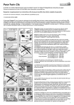
SIDE-POWER PJC321, PJC322 PJC321-L, PJC322-L PJC321-MCL2, PJC322-MCL2 S-link Control Panel Thruster Systems Installation and user’s manual v 1.0.6 is rd th a p bo ee n K al o u an m ! SLEIPNER MOTOR AS P.O. Box 519 N-1612 Fredrikstad Norway Tel: +47 69 30 00 60 Fax: +47 69 30 00 70 w w w. s i d e - p o w e r. c o m s i d e p o w e r @ s l e i p n e r. n o Made in Norway EN © Sleipner Motor AS 2014 Content Declaration of Conformity ..............................................................................................................................................................................2 Product Features...............................................................................................................................................................................................3 Display in normal use.......................................................................................................................................................................................3 Technical specifications...................................................................................................................................................................................4 Display warnings and alarms ...................................................................................................................................................................... 5-6 Menu system ................................................................................................................................................................................................ 6-9 1.5 Language...................................................................................................................................................................................7 2.5 Display settings.........................................................................................................................................................................7 3.5 Automatic off time....................................................................................................................................................................7 4.5 Control setup........................................................................................................................................................................ 7-9 Service menu.................................................................................................................................................................................................. 10 Panel mounting.............................................................................................................................................................................................. 10 Panel dimensions........................................................................................................................................................................................... 11 Panel dimensions PJC322............................................................................................................................................................................ 12 Panel dimensions PJC321............................................................................................................................................................................ 13 Panel dimensions PJC321-L/PJC322-L....................................................................................................................................................... 14 Panel dimensions PJC321-MCL2/PJC322-MCL2...................................................................................................................................... 15 S-Link overview.............................................................................................................................................................................................. 16 Internal wiring diagram PJC321, PJC322................................................................................................................................................... 17 Internal wiring diagram PJC321-L, PJC322-L............................................................................................................................................ 18 Internal wiring diagram PJC321-MCL2, PJC322-MCL2............................................................................................................................ 19 DECLARATION OF CONFORMITY We, Sleipner Motor AS P.O. Box 519 N-1612 Fredrikstad, Norway declare that this product with accompanying standard remote control systems complies with the essential health and safety requirements according to the Directive 89/336/EEC of 23 May 1989 amended by 92/31/EEC and 93/68/EEC. 2 PJC321/322 version 1.0.6 - 2014 for over 35 years operated as a well-known manufacturer of remote control systems for main hrusters and joystick & position control systems, and has delivered a total of about 3000 tems are designed to suit all demands from a modern fleet, where our extensive experience ™ CAN-bus e systems are designed according the fail-safe principle andconnection are built up with a high level of Control panel withtoS-link very user friendly, highly accurate, advanced and flexible with many possibilities. PJC321, PJC322 Product features well-established supplier of high quality components to the professional market in Norway, • For proportional thruster control with the S-Link controlled Hydraulic Thrusters uppliers of MMI, sensors, actuating units and instrumentation. ns • Back-lit LCD display with instant feedback - System status - Amount of thrust & direction of thrust - Oil temperature & pressure • Interactive multi-language menus • CAN-Bus communication with thrusters and accessories versions of&the MCL2 control pictures below show the visual • Plug play cables, waterproof andlever. compactThe connectors ons for non-visual • the Diagnostics via panel properties (d-e-f) are found in 'How to specify'. n • Connector for external “buzzer”/loud audible alarms • Choose between: LF90 Control lever MCL2-SLR-C-L1-d-e-f • One handle • Right side • Fwd. curved • ±100% PJC321-L/PJC322-L PJC321-MCL2/PJC322-MCL2 Single or double operation of tunnel thruster/ propulsion machinery. PJC322 PJC321 MCL2-DL-C-L1-d-e-f MCL2-DL-C-L2-d-e-f • Two handles • Two handles LF90 is designed for single or double operation of tunnel thruster and propulsion machinery. Small, robust and established as one of the most reliable maritime control levers on the market. The standard lever may be modified according to customer’s requirements, such as panel plate, different scales, straight or curved shafts (standard Lilaas thruster control = curved shafts), different handles, potentiometers, detents and switch operation. DO NOT connect any other control equipment to the S-link controlled products except • Fwd. curved • Fwd. curved supplied interface product made Side-Power original S-link products or via a Side-Power Both ±100% • 0-100% left control or at all connect into for •interfacing with other controls. Any attempt to directly the S-link control system without the designated approved interface, will render all • ±100%and right warranties and responsibilities for the complete line of Side-Power products connected void and null. If you are interfacing by agreement with Sleipner and through a designated and approved interface, you are still required to also install an original Side-Power control panel to enable efficient troubleshooting if necessary Note: Separate product sheets for motorized versions of LF90/LF120 Talk to us: +47 33 03 18 50 [email protected] More information www.lilaas.no MCL2-DT-S-T0-d-e-f DISPLAY IN NORMAL USE: • Two handles • Straight 1 hydraulic tank Oil Temperature • Both ±100% 2 hydraulic tanks Oil Temperature, Port Tank Oil Temperature, Starboard Tank Thrust power and direction d-e-f. Example order code: MCL2-DL-CS-L2-0-2-0. tudinal, Left side. d: 0 - Potentiometer without CT (double: both). tudinal, Right side. 1 - Potentiometer with CT (double: both). itudinal. 2 - Left/upper with CT, Right/lower without CT. verse, Lower side. 3 - Left/upper without CT, Right/lower with CT. Buttons/Indications on screen - left to right: verse, Upper side. CTmode = Centre Tap. All STOP versions single track ON/OFF - DAYTIME/NIGHT Backlight - EMERGENCY - SETTINGS MENU5kΩ. sverse. ble: both). e: 0 - 3,3VDC backlight. ble: both). 1 - 5VDC backlight. PJC321/322 version 1.0.6 - 2014 ight/lower straight. 2 - 24VDC backlight. 3 Technical specifications Description Value Operating temperature –40°C to +70°C [–40°F to +158°F] Storage temperature –40°C to +85°C [–40°F to +176°F] IP Rating IP67 above panel EMC tested Acc. to EN 13309, ISO 14982, ISO 13766 ESD tested Acc. to EN 61000-4-2, ISO 7637-2 Power 9-63 Vdc / 6.5 Watts EMC/ESD 100V/m/15kV Vibration/Shock 3g/50g External Alarm Buzzer Current 0.5A Maximum Weight 250 g [0.5 lb] Supply Voltage 4 9-63 Vdc/6.5 Watts PJC321/322 version 1.0.6 - 2014 Display Warnings & Alarms PANEL FILTER MONITORING WARNINGS (IF SENSORS ARE INSTALLED) PRESSURE FILTER: Pressure filter symbol (upper right) will blink when filter change is due. In addition red LEDs on both sides of the panel will blink and the external buzzer is activated. RETURN FILTER: Return filter symbol (lower right) will blink when the filter needs to be replaced. In addition red LEDs on both sides of the panel will blink and the external buzzer is activated. The external buzzer can be muted by pressing the button under the loudspeaker symbol. Warnings will be reset when the filter are replaced. The thrusters can be run while the warnings is displayed. (Filter warnings will not be shown on systems with two oil tanks) ALARMS (Systems with one oil tank) OIL LEVEL: Oil level symbol (upper left) will blink when oil level is low. In addition red LEDs on both sides of the panel will blink and the external buzzer is activated. The alarm will be reset automatically when the oil level is OK OIL TEMPERATURE: Oil temperature symbol (lower left) will blink when temperature is above 75oC. In addition red LEDs on both sides of the panel will blink and the external buzzer is activated. The alarm will be reset automatically when temperature goes below 65oC The thrusters can be run when the oil alarms are active. COMMUNICATION ERROR: If there is a communication error between the panel and the system control unit located on the oil tank, the comm error symbol will be shown on the lower left side of the panel The external buzzer can be muted by pressing the button under the loudspeaker symbol. ALARMS (Systems with two oil tanks) OIL LEVEL: Oil level symbol (upper left/right) will blink when oil level is low. In addition red LEDs on both sides of the panel will blink and the external buzzer is activated. The alarm will be reset automatically when the oil level is OK OIL TEMPERATURE: Oil temperature symbol (lower left/right) will blink when temperature is above 75oC. In addition red LEDs on both sides of the panel will blink and the external buzzer is activated. The alarm will be reset automatically when temperature goes below 65oC. The thrusters can be run when the oil alarms are active. COMMUNICATION ERROR: If there is a communication error between the panel and the system control unit located on the oil tank, the communication error symbol will be shown on the lower left/right side of the panel Symbols on left side indicates port tank, symbols on right indicates starboard tank. The external buzzer can be muted by pressing the button under the loudspeaker symbol. PJC321/322 version 1.0.6 - 2014 5 Display Warnings & Alarms AC MOTOR ALARMS PANEL HYDRAULIC AC MOTOR POWER PACK OVERTEMP: The overtemp symbol will show in the upper right corner of the display when the AC motor temperature is above 120°C and automatically reset when temperature goes below 110°C. HYDRAULIC AC MOTOR POWER PACK TEMP SENSOR: The AC motor temp sensor fail symbol will show in the upper right corner if the system is set up with an hydraulic AC motor power pack and the sensor has an open circuit. EMERGENCY STOP When the STOP button is pressed, the hydraulic dump valve will activate and the thrusters will stop. On systems with two oil tanks, dump valves on both tanks will activate and all thrusters will stop. The EMERGENCY STOP ACTIVATED symbol will be shown on the display. In addition red LEDs on both sides of the panel will blink and the external buzzer is activated. NB: FOR EMERGENCY STOP ONLY! Press STOP again to reactivate the hydraulic system. The external buzzer can be muted by pressing the button under the loudspeaker symbol. Menu System Access menu system by pressing menu button and hold it for 3 seconds SETTINGS The menu system contains of 5 settings: 1 - Language 2 - Display Settings 3 - Automatic OFF time 4 - Control Setup 5 - Panel Postition Select settings Exit settings Choose function 6 PJC321/322 version 1.0.6 - 2014 Menu System 1/5 Language Choose between English or Norwegian. The setting will not affect other panels in the system. PANEL 2/5 Display settings Set contrast and backlight level for Daytime/Night modes Settings will not affect other panels in the system. Press backlight. to start adjustment - Press + or - to adjust contrast or Use to switch between daytime or night settings. Exit setting by pressing Adjustments will automatically end after 3 seconds of inactivity. 3/5 Automatic OFF time Set time from last activity to Panel automatically turns off. The time can be set at 5 minutes interval, ranging from 5 to 60 minutes - or be disabled. When “Disabled” is selected, the panel will never be turned off automatically. Settings will not affect other panels in the system. Press to adjust time in 5 minutes intervals. Exit setting by pressing Store settings by pressing 4/5 Control Setup 1.1 Bow/Stern Direction: Values: Normal (default)/Inverted Switches between Normal and Inverted running direction for the thruster. Direction need to be inverted if incorrect prop rotation. PJC321/322 version 1.0.6 - 2014 7 Menu System 1.2 Pump Control (PTO Mounted Pump) Values: Power Save(default)/Always ON PANEL When «Pump Control» is set to « Power Save», the system will automatically control load sharing between two PTO pumps by deactivating the secondPTO pump when not needed (two PTO pumps/ control valves required) to reduce heat generation in the system and save fuel/energy. When any thruster is running, both PTO pumps will be active to ensure good performance. When an SPS stabilizer system is active, one PTO pump will be deactivated to save power. If stabilizers are active and the system pressure drops below 80bar, the system will activate the second PTO pump for 15 minutes to increase the flow capacity and maintain required pressure. After 15 minutes the second pump will be deactivated unless the pressure is still below 80 bar. “Pump Control” settings has no effect when “Thruster Stern” is set to “W/Bypass Valve”. NOTE: “Pump Control: Auto” must only be used on PHC 024 with firmware V.1.008 or higher! 1.3 Cooling Pump Values: Temp Controlled(default) / Always Running When the option “Temp Controlled” is selected, the cooling pump will start when oil temperature exceeds 50°C/122°F and stop when the oil temperature goes below 40°C/104°F. On systems with two oil tanks, this setting will apply to both tanks. 1.4 Cooling Signal Output Values: Normal (default)/Inverted Set to Normal when using a hydraulic cooling pump. Should be set to Inverted when using an electrical cooling pump with a 10 2380A-12/24V relay box. 1.5 Cooling Power Save Values: ON (default)/OFF ON sets the Cooling Pump into power save mode, which means the Cooling Pump output is dropping to 0 volt when the oil pressure is below 10 bar for more than 10 seconds (Cooling Pump is turned OFF). 1.6 Tank Monitor Values: ON (default)/OFF ON is when you have a tank monitor, oil level and Oil temp sensor. OFF is when you do not have a tank monitor and the display will show 0°C and no alarm for high temperature or low level will not be transmitted on the S-link. 8 PJC321/322 version 1.0.6 - 2014 Menu System 1.7 Thruster Bow (only available for PHC024 FW with V1.105 or higher) Values: WO/Bypass Valve (default)/ W/Bypass Valve PANEL All 513mm (20inch) tunnel and 610mm (24inch) tunnel thrusters, are supplied with hydraulic bypass/crossover valve and must be set to “W/Bypass Valve”. This bypass valve is normally open to protect the thruster during deceleration and will close while thruster is running. By selecting “W/Bypass Valve” you activate this signal and addition change ramp parameters to match this setup. All other thrusters must be set to “WO/Bypass Valve”. 1.8 Thruster Stern (only available for PHC024 with FW V1.105 or higher) Values: WO/Bypass Valve (default)/ W/Bypass Valve All 513mm (20inch) tunnel and 610mm (24inch) tunnel thrusters, are supplied with hydraulic bypass/crossover valve and must be set to “W/Bypass Valve”. This bypass valve is normally open to protect the thruster during deceleration and will close while thruster is running. By selecting “W/Bypass Valve” you activate this signal and addition change ramp parameters to match this setup. All other thrusters must be set to “WO/Bypass Valve”. 1.9 Instance Values: --(default)/Port/Starboard Setting the PHC024 tank controller instance. For a mono hull boat the instance should be ”--“. If you have a catamaran with two PHC024 controllers then the one in the port hull should be set as “Port” and the one in the starboard hull as “Starboard”. This way the two controllers are shown in the panel display as two different oil tanks to monitor. 1.10 Thruster Valves (only apply for PHC024 with FW V1.105 or higher) Values: Bow-Stern (default)/ Bow-Bow / Stern-Stern Thruster Valves is how the two thruster valves are set to work. Bow-Stern: One thruster valve output runs on bow signal from control device, and the other thruster valve output runs on stern signal from control device. Bow-Bow: Both thruster valve outputs runs on bow signal from control device. Stern-Stern: Both thruster valve outputs runs on stern signal from control device. PJC321/322 version 1.0.6 - 2014 9 Menu System SERVICE MENU (Systems with one oil tank) Access SERVICE MENU by pressing MENU button PANEL Shows oil pressure and temperature in the hydraulic tank as well as the serial number of the panel. Thrusters can be operated while this display is shown. Exit Service Menu by pressing SERVICE MENU (Systems with two oil tanks) Shows oil pressure and temperature in both hydraulic tanks as well as the serial number of the panel. Thrusters can be operated while this display is shown. Exit Service Menu by pressing Panel mounting TECHNICAL SPECIFICATIONS, LCD DISPLAY: IP 67 Low temp functionality (-40oC) Mounting bracket Alarm output max load 200mA Input voltage 9 - 31V Max current consumption 110mA 10 PJC321/322 version 1.0.6 - 2014 Panel Dimensions PJC321/322 version 1.0.6 - 2014 11 Panel Dimensions, PJC322 This wizard is for measurements use only! Use external wizard when mounting 12 PJC321/322 version 1.0.6 - 2014 Panel Dimensions, PJC321 This wizard is for measurements use only! Use external wizard when mounting PJC321/322 version 1.0.6 - 2014 13 Panel Dimensions, PJC321-L, PJC322-L LF90 Control lever LF90 Control lever This wizard is for measurements use only! Use external wizard when mounting Single or double operation of tunnel thruster/ propulsion machinery. LF90 is designed for single or double operation of tunnel thruster and propulsion machinery. Small, robust and established as one of the most reliable maritime control levers on the market. The standard lever may be modified according to customer’s requirements, such as panel plate, different scales, straight or curved shafts (standard Lilaas thruster control = curved shafts), different handles, potentiometers, detents and switch operation. Note: Separate product sheets for motorized versions of LF90/LF120 Talk to us: +47 33 03 18 50 [email protected] More information www.lilaas.no Single or double operation of tunnel thruster/ propulsion machinery. LF90 is designed for single or double operation of tunnel thruster and propulsion machinery. Small, robust and established as one of the most reliable maritime control levers on the market. The standard lever may be modified according to customer’s requirements, such as panel plate, different scales, straight or curved shafts (standard Lilaas thruster control = curved shafts), different handles, potentiometers, detents and switch operation. Note: Separate product sheets for motorized versions of LF90/LF120 Talk to us: +47 33 03 18 50 [email protected] 14 PJC321/322 version 1.0.6 - 2014 More information www.lilaas.no Examples of standard versions of the MCL2 control lever. The picture differences. for the properties (d-e-f) fou Examples ofSpecifications standard versions of non-visual the MCL2 control lever. The are picture differences. Specifications for the non-visual properties (d-e-f) are fou Longitudinal motion Panel Dimensions PJC321-MCL2, PJC322-MCL2 Longitudinal motion MCL2-SLR-C-L0-d-e-f This wizard is for measurements use only! Use external wizard when mounting MCL2-SLR-C-L0-d-e-f • One handle side • Right One handle • Fwd. Right curved side • Fwd. 0-100% curved • 0-100% MCL2-SLR-C-L1-d-e-f MCL2-SLR-C-L1-d-e-f • One handle side • Right One handle • Fwd. Right curved side • Fwd. ±100% curved • ±100% MCL2-DL-C-L0-d-e-f MCL2-DL-C-L0-d-e-f • Two handles curved • Fwd. Two handles • Fwd. Both 0-100% curved • Both 0-100% MCL2-DL-C-L1-d-e-f MCL2-DL-C-L1-d-e-f • Two handles curved • Fwd. Two handles • Fwd. Both ±100% curved • Both ±100% Transverse motion Transverse motion MCL2-STL-S-T0-d-e-f MCL2-STL-S-T0-d-e-f • One handle • Straight One handle • Lower Straightside • Lower ±100%side • ±100% MCL2 MCL2 • Two • Fwd. Two • Fwd. 0-100 • ±100 0-100 • ±100 MCL2-DT-S-T0-d-e-f MCL2-DT-S-T0-d-e-f • Two handles • Straight Two handles • Straight Both ±100% • Both ±100% How to specify How toMCL2-a-b-c-d-e-f. specify General: Example order code: MCL2-DL-CS-L2-0-2 a: SLL - Single handle, Longitudinal, Example Left side. order code:d:MCL2-DL-CS-L2-0-2 0 - Potentiometer without General: MCL2-a-b-c-d-e-f. SLR - Single handle, Longitudinal, Right side. 1 - Potentiometer with CT a: SLL - Single handle, Longitudinal, Left side. d: 0 - Potentiometer without DL - Double handle, Longitudinal. 2 - Left/upper with CT, Ri SLR - Single handle, Longitudinal, Right side. 1 - Potentiometer with CT STL - Single handle, Transverse, Lower side. 3 - Left/upper without CT DL - Double handle, Longitudinal. 2 - Left/upper with CT, Ri STU - Single handle, Transverse, Upper side. CT Centre Tap. All vers STL - Single handle, Transverse, Lower side. 3 - =Left/upper without CT DT - Double handle, Transverse. STU - Single handle, Transverse, Upper side. CT = Centre Tap. All vers b: DT C Curved handle, handle (double: both). e: 0 - 3,3VDC backlight. -- Double Transverse. S - Straight handle (double: both). 1 - 5VDC backlight. b: C - Curved handle (double: both). e: 0 - 3,3VDC backlight. CS - Left/upper curved, Right/lower straight. 2 - 24VDC backlight. S - Straight handle (double: both). 1 - 5VDC backlight. SC - Left/upper straight, Right/lower curved. CS - Left/upper curved, Right/lower straight. 2 - 24VDC backlight. c: SC L0 -- Left/upper Longitudinal scale 0-100. f: 0 - Standard sealing (indo straight, Right/lower curved. L1 - Longitudinal scale 100-0-100 (i.e. ±100). 1 - IP56 protection. c: L0 - Longitudinal scale 0-100. f: 0 - Standard sealing (indo L2 - Longitudinal scale 0-100 left, 100-0-100 right. L1 - Longitudinal scale 100-0-100 (i.e. ±100). 1 - IP56 protection. T0 - Transverse scale 100-0-100 (i.e. ±100). L2 - Longitudinal scale 0-100 left, 100-0-100 right. Left/Right for longitudinal Upper/Lower for transverse motion. Curved handle means T0 - Transverse scalemotion, 100-0-100 (i.e. ±100). motion and towards right for transverse motion. Mechanical centre point at 0 when 100-0-100 s Left/Right for longitudinal motion, Upper/Lower for transverse motion. Curved handle means with red backlight. motion and towards right for transverse motion. Mechanical centre point at 0 when 100-0-100 s with red backlight. Contact Scana Mar-El for custom designing, other signal outputs etc. Contact Scana Mar-El for custom designing, other signal outputs etc. PJC321/322 version 1.0.6 - 2014 15 PJC321/322 version 1.0.6 - 2014 16 S-Link overview PJC321/322 version 1.0.6 - 2014 Internal Wiring Diagram PJC321, PJC322 17 18 PJC321/322 version 1.0.6 - 2014 LF90S-01-37 (PJC321-L) / LF90D-01-127-REV-C (PJC322-L) Internal Wiring Diagram PJC321-L, PJC322-L Display unit PJC321/322 4 3 7 1 12 2 6 black red black red blue white red violet version 1.0.6 - 2014 19 3 1 2 3 grey brown blue yellow 3 2 1 3 2 YE RD GN GN RD - + - + Part nr Date Material Type Sleipner Motor AS Approved by BU RD STERN STERN 2 R.Holm 6x0,75 LiYCY BOW BOW 1 1 YE white pink Copyright All rights reserved Designed by CAN connector shield + - Alarm buzzer output (optional) max 200 mA 24.07.2012 Drawing nr Edition Joystick STERN Joystick BOW Wiring diagram PJC322-MCL2 Date BOTTOM Joystick Type Scana TOP MCL2-DT-S-TO-O-2-1 Sleipner Panel facing bow!! 1/1 Sheet Internal Wiring Diagram PJC321-MCL2, PJC322-MCL2 Worldwide sales and service www.side-power.com SLEIPNER MOTOR AS P.O. Box 519 N-1612 Fredrikstad Norway Tel: +47 69 30 00 60 Fax:+47 69 30 00 70 www.side-power.com [email protected]