1
APPLICATION NOTE
Atmel AT06700: LED Commercial Lighting Kit and
Gateway Software User’s Guide
Atmel 8/32-bit Microcontroller
Description
This application note describes the achievement of LED commercial light application
function which includes light control, information collection and link maintaining. It
enables the Atmel® AVR® wireless MCU and ARM® MCU user to get start using
Atmel proprietary lightweight mesh software stack and understand how to configure,
use and integrate the devices in their own design.
A getting started guide in Chapter 5 provides detailed setup and operation of
preprogrammed firmware.
Features
•
•
•
•
•
Atmel ATSAM3X8E ARM Microcontroller, AT86RF231 Transceiver
Atmel ATMEGA256RFR2 Microcontroller
Atmel proprietary Lightweight Mesh software stack V1.01
Lightweight IP stack V1.4.0
Light control, information collection and link maintaining
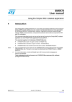
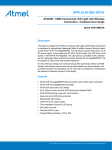
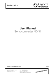
Figure 1.
LED Commercial Light Kit and Gateway.
LED Light Adapter
Lightweight Mesh
Device
Gateway
The lightweight Mesh version is V1.01. Refer to Atmel AVR2130: Lightweight Mesh
Developer Guide and Atmel AVR2131: Lightweight Mesh Getting Started Guide for
detailed lightweight Mesh introduction.
For this reference design, the hardware design files (schematic, BOM, and PCB
Gerber) and software source code can be downloaded from Atmel website. The
provided hardware documentation can be used with not limitations to manufacture
the reference hardware solution for the design.
42236A−MCU−02/2014
Table of Contents
1. Overview .............................................................................................. 3 1.1 Coordinator (Gateway kit) ................................................................................. 3 1.2 Device (Lighting Kit) .......................................................................................... 3 1.3 LED Light Adapter ............................................................................................. 3 1.4 The Whole System Topology ............................................................................ 3 2. Development Tools .............................................................................. 4 3. Gateway Firmware Introduction ........................................................... 4 3.1 Inside the Applications ...................................................................................... 4 3.1.1 Lightweight Mesh Task ....................................................................... 5 3.1.2 Lightweight IP Task ............................................................................ 6 3.1.3 Application Layer Task........................................................................ 8 3.2 Main API Introduction ........................................................................................ 9 3.2.1 Lightweight Mesh APIs ....................................................................... 9 3.2.2 Lightweight IP APIs ............................................................................. 9 3.3 Software Package Content ............................................................................. 11 4. Device Firmware Introduction ............................................................ 12 4.1 Device Link Mechanism .................................................................................. 12 4.2 LED Light Management .................................................................................. 12 4.3 Main API Introduction ...................................................................................... 13 4.4 Software Package Content ............................................................................. 13 5. Getting Started Guide ........................................................................ 14 5.1 Lightweight Mesh Parameters Configuration .................................................. 14 5.2 Lightweight IP Parameters Configuration ........................................................ 15 5.3 Program the Target Board .............................................................................. 16 5.4 Connecting to Ethernet ................................................................................... 18 6. Application Layer Communication Introduction .................................. 20 6.1 Communication Method .................................................................................. 20 6.2 Communication Command Set ....................................................................... 21 6.2.1 Device Link Request (CMD_DEV_LINK_REQ) ................................ 21 6.2.2 Request Command Query (CMD_CMD_QUERY_REQ) .................. 21 6.2.3 LED Light Grouping (CMD_LED_GROUPING) ................................ 22 6.2.4 Device Status Query (CMD_DEV_STAT_REQ) ............................... 22 6.2.5 Single LED Control (CMD_LED_SINGLE_CTRL) ............................ 23 6.2.6 Group LED Control (CMD_LED_ GROUP_CTRL) ........................... 23 6.2.7 Time Synchronization (CMD_TIME_SYNC) ..................................... 24 6.2.8 Single LED Timing Set (CMD_ LED _SINGLE_TIMING_SET) ......... 24 6.2.9 Group LED Timing Set (CMD_ LED _GROUP_TIMING_SET) ......... 24 Appendix A. Additional Information .................................................... 25 A.1 Lightweight Mesh Configuration ...................................................................... 25 A.2 Application Communication Command Set ..................................................... 25 Appendix B. Revision History ............................................................ 26 Atmel AT06700: LED Commercial Lighting Kit and Gateway Software User’s Guide
[APPLICATION NOTE]
42236A−MCU−02/2014
2
1.
Overview
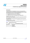
The LED Commercial light based on lightweight Mesh stack protocol communicating is designed to passively receive
data /command from a Coordinator (except the device request link command), it means the communication beginner is
always a Coordinator. A device can be set as an “End device” or a “Router”, when a device is set to a Router, this
device (Router) should route the data from a Coordinator or from an End device/Router if the target address is not for
itself. A typical application scenario is shown in Figure 1-1.
Figure 1-1. Typical Lightweight Mesh Network Application Scenario
1.1
Coordinator (Gateway kit)
The Coordinator which address is 0x0000 is in charge of:
•
•
•
Periodically collect Devices’ information, based on the device link list then report to PC server
Transfer PC server command to a device
Device’s request link command response and maintains device link list
Coordinator is usually integrated into TCP/IP-to-Lightweight Mesh Gateway. There are two roles for Gateway, TCP/IP
client for TCP/IP communication and Coordinator for lightweight Mesh communication.
1.2
Device (Lighting Kit)
The Device which could be End device or Router is deployed into LED commercial light for LED controlling and
information report through lightweight communication. Two responsibilities for the Device:
•
•
Request device link
Executes control command and responses query command from Coordinator
If the Device is configured as a Router it would route the data from a Coordinator or from an End device/Router if the
target address is not for itself.
1.3
LED Light Adapter
LED light adapter which is made by ATxmega8E5 is the power supply of LED light. In this application, we don’t plan to
introduce the function of LED light adapter and how to achieve the function. The elf file has been provided for its
programming. Refer to Section 5.3 Program the Target Board for the specific LED light adapter program operation.
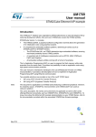
1.4
The Whole System Topology
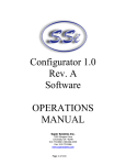
The system usually includes four parts: LED light, Gateway, TCP/IP Server and User (TCP/IP Client). The Gateway
would periodically communicate with Server for LED light information uploading after connected with the Server. The
Server and User can control LED light and collect LED light information through communicating with Gateway, but the
User can’t directly communicate with Gateway, it needs data transfer through the Server after collected with the Server.
Refer to Figure 1-2 for the whole system topology.
Atmel AT06700: LED Commercial Lighting Kit and Gateway Software User’s Guide
[APPLICATION NOTE]
42236A−MCU−02/2014
3
Figure 1-2. The Whole System Topology
Lightweight Mesh Network(LED light)
Server
TCP/IP
Gateway
TCP/IP
Internet
TCP/IP
TCP/IP
Gateway
TCP/IP
Gateway
2.
User
Development Tools
To program or debug the preprogrammed firmware, the following development tool chain is needed:
3.
•
•
•
•
Atmel Studio 6. Version: 6.1.2514 - beta or above
•
JTAGICE3 adapter: 50-mil 6-pin
Atmel Software Framework. Version: 3.5.1 or above
Programming and debugging device: Atmel JTAGICE3, SAM-ICE™ JTAG
SAM-ICE Adapter: a minimized (1.27mm pitch 10-pin header) adapter for Atmel SAM-ICE. For more details
refer to Atmel AVR2033: SAM-ICE Adapter - Hardware User Manual
Gateway Firmware Introduction
The Gateway is based on Atmel ATSAM3X8E microcontroller and Atmel AT86RF231 2.4GHz radio transceiver. For
gateway hardware design details, refer to Atmel AT2200: ZigBee® to Ethernet and Wi-Fi Gateway with SAM3X Hardware User's Guide.
3.1
Inside the Applications
There are two tasks in Gateway firmware, lightweight IP application task and lightweight Mesh application task. The
LED commercial light application task is integrated into lightweight IP application task. The content of main () function is
shown below:
int main(void)
{
sysclk_init();
board_init();
ledsInit();
/* Bring up the Ethernet interface & initializes timer 0, channel 0 */
LwIP_Init();
while(1){
/* Check if any packets are available and process if they are
* ready. That function also manages the lwIP timers */
LwIP_App_Task_Hander();
/* lwMesh initialization, Check if any packets are available and
process if they are
ready. also manages the LwMesh task and timers*/
LwMesh_App_Task_handler();
}
/* Never reached */
return 0;
}
Atmel AT06700: LED Commercial Lighting Kit and Gateway Software User’s Guide
[APPLICATION NOTE]
42236A−MCU−02/2014
4
Function sysclk_init(),board_init() and ledsInit() is respectively used to initialize MCU system clock, target board
configuration, and network status indicator LED initialization. Function LwIP_Init() , LwIP_App_Task_Hander() and
LwMesh_App_Task_handler() have been described in the code comment above.
3.1.1
Lightweight Mesh Task
Atmel lightweight Mesh is the easy-to-use proprietary low power wireless mesh network protocol from Atmel. It is
designed to work with all Atmel IEEE® 802.15.4 transceivers and SoCs. To find more detailed information about the
lightweight Mesh architecture and application development process, refer to Atmel AVR2130: Lightweight Mesh
Developer Guide.
The software block diagram lightweight Mesh software stack is given in Figure 3-1.
Figure 3-1. The Lightweight Mesh Software Block Diagram
Currently the public release version of lightweight Mesh software stack works with AVR®-based MCUs, but given its
extreme portability and low resource requirements, it can be run on almost any Atmel MCU. In this application, it‘s
integrated into ATSAM3X8E MCU for Gateway and ATmega256RFR2 for the LED commercial light, the version is
v1.01.
In order to improve the efficiency of Gateway information collection, maximum Device quantity is limited; the default is
200, 50 for Router and 150 for End device. So the Router address is from 0x0001 to 0x0032 and the End device is from
0x8001 to 0x8096.
Lightweight Mesh application task includes two parts: lightweight Mesh initialization SYS_Init() and lightweight Mesh
task handle SYS_TaskHandler():
Function LwMeshApp_Init() is as below:
static void LwMeshApp_Init(void)
{
/* Config LwMesh */
SYS_Init();
NWK_SetAddr(APP_ADDR);
NWK_SetPanId(APP_PANID);
PHY_SetChannel(APP_CHANNEL);
PHY_SetRxState(true);
NWK_OpenEndpoint(APP_ENDPOINT, rf_rx_handler);
nwk_data_req.dstEndpoint = 1;
nwk_data_req.srcEndpoint = 2;
nwk_data_req.options = 0;
nwk_data_req.confirm = rf_tx_finish_handler;
}
Atmel AT06700: LED Commercial Lighting Kit and Gateway Software User’s Guide
[APPLICATION NOTE]
42236A−MCU−02/2014
5
SYS_Init(), is called to initialize lightweight Mesh system stack and specific hardware interface configuration. Function
NWK_SetAddr() is used for lightweight Mesh Device address initialization. APP_ADDR Macro has two functions: one
for configuring Device address, another is to identify the Device is a Router (<0x8000) or an End device (>=0x8000).
For Gateway, Macro APP_ADDR must be 0 (Coordinator).
In order to create communication between Gateway and Device, The Gateway and Device must be configured as same
Personal Area Network ID, Physical Channel and Application Endpoint through function NWK_SetPanId(),
PHY_SetChannel() and NWK_OpenEndpoint ().
Macro APP_PANID with a range of 0-65535 is to predefine Personal Area Network ID number; Macro APP_CHANNEL
must be in the range of 11-26 for configuring communication Physical Channel number, for the specific channel
frequency, refers to AT86RF231 or Atmega256RFR2 datasheet. Macro APP_ENDPOINT with a range of 0-15 is to set
the Application Endpoint number, the callback function of lightweight Mesh data receive handle rf_rx_handler() is also
initialized through function NWK_OpenEndpoint ().
nwk_data_req.confirm = rf_tx_finish_handler is used to set lightweight Mesh application layer data send finished
callback function.
Function SYS_TaskHandler() is responsible for running lightweight mesh stack. Function NWK_DataReq() is
responsible for sending lightweight mesh application layer data. Make sure that the lightweight Mesh is idle
(NWK_Busy() is used to detect whether the lightweight Mesh is busy or not) before sending application layer data.
3.1.2
Lightweight IP Task
Lightweight IP is free third party software stack mainly for embedded operation platform, Refer to lightweight IP website
for more information.
Lightweight IP application task mainly includes two parts: lightweight IP initialization LwIP_Init() and lightweight IP task
handle LwIP_App_Task_Hander().
Function LwIP_Init() is in charge of lightweight IP stack initialization lwip_init() and Ethernet hardware interface
initialization ethernet_configure_interface(). We use static local IP address in this application, so the Ethernet hardware
initialization includes IP address initialization, subnet mask initialization, default gateway address initialization and MAC
address initialization. See following code in function LwIP_Init() below.
/* Default ip addr */
IP4_ADDR(&x_ip_addr, ETHERNET_CONF_IPADDR0, ETHERNET_CONF_IPADDR1,
ETHERNET_CONF_IPADDR2, ETHERNET_CONF_IPADDR3);
/* Default subnet mask */
IP4_ADDR(&x_net_mask, ETHERNET_CONF_NET_MASK0, ETHERNET_CONF_NET_MASK1,
ETHERNET_CONF_NET_MASK2, ETHERNET_CONF_NET_MASK3);
/* Default gateway addr */
IP4_ADDR(&x_gateway, ETHERNET_CONF_GATEWAY_ADDR0,
ETHERNET_CONF_GATEWAY_ADDR1,
ETHERNET_CONF_GATEWAY_ADDR2,
ETHERNET_CONF_GATEWAY_ADDR3);
netif_add(&gs_net_if, &x_ip_addr, &x_net_mask, &x_gateway, NULL,
ethernetif_init, ethernet_input);
Function ethernetif_init() called by function tcp_client_init() is responsible for the MAC address initialization and server
address initialization. The default server IP address is 192.168.1.58 and Port is 4008 as below.
static void static void tcp_client_init(void)
{
struct ip_addr ipaddr;
IP4_ADDR(&ipaddr,192,168,1,58);
Atmel AT06700: LED Commercial Lighting Kit and Gateway Software User’s Guide
[APPLICATION NOTE]
42236A−MCU−02/2014
6
struct tcp_pcb *pcb;
pcb = tcp_new();
gs_pcb = pcb;
if (pcb != NULL) {
tcp_err(pcb, tcp_err_handler);
tcp_bind(pcb, &gs_net_if.ip_addr, 0);
tcp_connect(pcb, &ipaddr, 4008, tcp_client_connected);
}
}
Lightweight IP task handle LwIP_App_Task_Hander() is in charge of lightweight IP stack polling and lightweight IP stack
timers updating through function ethernetif_input() and timers_update().
Callback function tcp_client_received() is responsible for receiving and handling TCP/IP application layer data and
function tcp_write() is called for sending application layer data to TCP/IP server.
Function tcp_client_connected() is invoked when a TCP/IP connection is established. It sends a string to TCP/IP server
after successful connection and set TCP client in receiving state by registering a callback function tcp_client_received().
Function status_callback() is the callback function for a status change in default network interface. It initializes the
Gateway as TCP/IP client by calling tcp_client_init().
Function tcp_err_handler() is the callback function for TCP error handler. It re-initializes Gateway to TCP/IP client if
connection is aborted or connection reset occurs in lightweight IP.
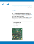
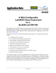
Refer to Figure 3-2 for specific lightweight IP stack running mechanism.
Figure 3-2. Lightweight IP Task Flow Diagram
lwip_init
ethernet_configure_interface
ethernet_task
Data received?
No
Yes
No
IP packet?
Yes
No
ARP packet?
ip_input
Yes
etharp_arp_input
TCP protocol?
No
Yes
tcp_input
Other protocol handler
tcp_client_received
tcp_write
tcp_output
Atmel AT06700: LED Commercial Lighting Kit and Gateway Software User’s Guide
[APPLICATION NOTE]
42236A−MCU−02/2014
7
3.1.3
Application Layer Task
Gateway application task mainly includes three functions:
1.
2.
3.
TCP/IP server command transfer and response TCP/IP Server query command.
LED light information periodic query, collection and report.
LED light link list maintaining.
TCP/IP Server command transfer and query command is based on the lightweight IP task, according to predefined
command set, application task decides whether the command should be transferred to LED light through lightweight
Mesh or not. For specific command definition, refer to Section 6.2 Communication Command Set.
There are two timer handle functions rfDataQueryTimerHandler() and rfDataCollectionTimerHandler() for LED light
information query. rfDataQueryTimerHandler () is to periodically start LED light information query and
rfDataCollectionTimerHandler() is to start a timer to collect selected LED light information.
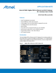
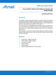
Refer to Figure 3-3 for the application task running mechanism.
Figure 3-3. Gateway Application Task Flow Diagram
Initialization
Light link list maintaining
Net data come?
Send relative
info to Server
no
Zigbee Device
link request
no
yes
no
Device info
query cmd?
ZigbeeDevice
query timer
timeout?
yes
no
yes
Got the
response
yes
yes
Finished?
yes
Update the device
link list
Got the
response
no
yes
no
Unicast cmd?
no
Send timeout
info to Server
Send request
query cmd to
Server
Send device info
query cmd based on
device link list
yes
Send success
info to Server
Response device link
request& update
device link list
yes
Send the Zigbee
control cmd
Send success
info to Server
yes
Timeout?
Command transfer and report
no
no
Timeout?
Light information query and collection
Atmel AT06700: LED Commercial Lighting Kit and Gateway Software User’s Guide
[APPLICATION NOTE]
42236A−MCU−02/2014
8
3.2
Main API Introduction
3.2.1
Lightweight Mesh APIs
The main APIs used in this application are as follows.
•
SYS_Init()
It initializes lightweight Mesh HAL, PHY, NWK layer and system timer. It is called from board_init().
•
SYS_TaskHandler()
It is the core API of lightweight Mesh. The PHY, NWK and system timer task handlers are called in
this API.
•
LwMesh_App_Task_Handler()
It is the application layer task handler of lightweight Mesh, also includes lightweight Mesh
initialization and lightweight Mesh core stack running.
•
rf_rx_handler()
The callback function registered by NWK_ NWK_OpenEndpoint(). It is called when valid data was
received from lightweight Mesh low level layer.
•
NWK_DataReq()
It is called for lightweight Mesh data sending, before calling this function, make sure that the network
is idle through calling NWK_Busy().
•
rf_tx_finish_handler()
It is initialized in LwMeshApp_Init(). It is called when the data sending is completed.
•
appRfNetworkTimeoutTimerHandler()
It is a timer timeout task handler of application layer and is used to indicate the waiting response
data timeout when the sending command is uni-cast command which needs a response.
•
appDataReceivedTimerHandler()
It is used to indicate through LED blinking that the system is receiving data through lightweight
stack.
•
appDataTransmitedTimerHandler()
It is used to indicate through LED blinking that the system is sending data through lightweight stack.
For more details about other APIs in lightweight Mesh, refer to the software package and documents inside. The latest
lightweight Mesh Software Stack package can be downloaded
from http://www.atmel.com/tools/LIGHTWEIGHT_MESH.aspx.
3.2.2
Lightweight IP APIs
The main APIs of lightweight IP used in application are as follows:
•
LwIP_Init()
It initializes lightweight IP Ethernet interface, related hardware and device link list.
•
LwIP_App_Task_Hander()
The lightweight IP Ethernet task handle, it polls the Ethernet tasks periodically; handles data transfer
between lightweight IP and lightweight Mesh, Device (LED light) data query and device link list
maintaining.
•
tcp_client_init()
It initializes the gateway as TCP/IP client. By default, static IP is assigned to gateway and a port
number is bound. In this function, it tries to connect to TCP/IP server with the default parameters.
•
tcp_client_received()
It’s the callback function invoked whenever a data packet is received from lightweight IP. For
Gateway, it stores data received from TCP/IP server in a buffer.
Atmel AT06700: LED Commercial Lighting Kit and Gateway Software User’s Guide
[APPLICATION NOTE]
42236A−MCU−02/2014
9
•
tcp_client_connected()
It’s the callback function invoked when a TCP connection is established. It sends a string to TCP
server after successful connection and set TCP client in receiving state by registering a callback
function tcp_client_received() in tcp_recv().
•
tcp_err_handler()
It’s the callback function for TCP error handle. It re-initializes Gateway to TCP/IP client if connection
is aborted or connection reset occurs in lightweight IP.
•
status_callback()
It’s the callback function for a status change in default network interface. It initializes the Gateway as
TCP/IP client by calling tcp_client_init().
•
rfDataQueryStartTimerHandler()
It is callback function for starting LED light information query. It is triggered by function
timers_update() through global timer table gs_timers_table[].
•
rfDataCollectionTimerHandler()
It is callback function for collecting LED light information after starting data query timer. It is
triggered by function timers_update() through global timer table gs_timers_table[].
For more details about lightweight IP APIs, refer to lightweight IP stack.
Atmel AT06700: LED Commercial Lighting Kit and Gateway Software User’s Guide
[APPLICATION NOTE]
42236A−MCU−02/2014
10
3.3
Software Package Content
The Gateway is developed based on ASF. The directory structure of the software package integrates ASF structure and
lightweight Mesh Software stack structure. For details of the structure of ASF, refer to Atmel AVR4029: Atmel Software
Framework - Getting Started. For the structure of lightweight Mesh, refer to Atmel AVR2130: Lightweight Mesh
Developer Guide.
The Gateway directory structure is shown as follows:
Figure 3-4. Gateway Directory Structure
Atmel AT06700: LED Commercial Lighting Kit and Gateway Software User’s Guide
[APPLICATION NOTE]
42236A−MCU−02/2014
11
4.
Device Firmware Introduction
In this application, Device is in charge of LED commercial light management and communicating with Gateway through
lightweight Mesh. The lightweight Mesh stack has been described in Gateway Function Introduction section, so in this
section, we would focus on Device link mechanism and LED light management from Device side.
4.1
Device Link Mechanism
In order to decrease possibility of the communication confliction between different devices, the random number
generator is used to produce the random time for requesting device link. Macro
NET_REQUEST_LINK_TIME_WINDOW is used to limit the time window, the default random time is from 0 to 32767
milliseconds.
Before using random number generator, the predefined Macro PHY_ENABLE_RANDOM_NUMBER_GENERATOR
must be enabled. Because the Gateway is designed to periodically query device information, so there is a timer insides
the Device to monitor the unicast data from the Gateway. If no data for NET_LOST_LINK_TIMEOUT milliseconds, the
Device would enter “no link “state, then the request data link function would be triggered. Figure 4-1 describes the
transfer of device link state.
Figure 4-1. Device Link Status
Initialization
Send “Request Device Link” command
Send “Request Device Link” command
Device isn’t linked
Device is linked
Wait command from Gateway timeout
Received unicast command
from Gateway
4.2
LED Light Management
Led light management includes five functions in this application:
•
LED self test: There is a dedicated timer TestTimer and function TestTimerHander() for LED self function
test.LED dimming value would be set from 0% to 100% then go back to 0% smoothly in the given time after
pressing the onboard button
•
LED timing control: The LED would be controlled by the preset timing value after enabling the timing settings
through communicating
•
•
LED manual control: The LED would be controlled through communication control command
•
Real time LED information collection: The system would collect the LED information periodically
LED autonomously control by light sensor: The LED would be controlled by the onboard light sensor
autonomously
Atmel AT06700: LED Commercial Lighting Kit and Gateway Software User’s Guide
[APPLICATION NOTE]
42236A−MCU−02/2014
12
4.3
4.4
Main API Introduction
•
APP_TaskHandler()
is in charge of lightweight Mesh initialization and application function initialization.
•
appDataInd()
is used for lightweight Mesh receiving data and handling.
•
appNetworkStatusTimerHandler()
is responsible for lightweight Mesh network status indictor and device link state timeout timing.
•
userKeyTimerHandler()
is used to judge whether the onboard button has been pressed down; it is designed for LED self test function.
•
appLinkingTimerHandler()
is called for Device link request.
•
appnetDataIndictorTimerHandler()
is used for receiving data indictor through LED display.
•
appCalendarReadTimerHandler()
is called to periodically update system time through reading calendar chip data.
•
appParameterUpdateTimerHandler()
is responsible for triggering LED parameters collection periodically.
Software Package Content
The LED light directory structure is as follows:
Figure 4-2. LED Light Directory Structure
Atmel AT06700: LED Commercial Lighting Kit and Gateway Software User’s Guide
[APPLICATION NOTE]
42236A−MCU−02/2014
13
5.
Getting Started Guide
In this chapter, it gives a step-by-step guide to configure the lightweight Mesh and lightweight IP and run the
preprogrammed firmware. It would have two sections for lightweight Mesh and lightweight IP configuration and
preprogrammed firmware.
5.1
Lightweight Mesh Parameters Configuration
Open the config.h file.
Figure 5-1. Device Lightweight Mesh Configuration
Figure 5-2. Gateway Lightweight Mesh Configuration
To start communication between End device, Router and Coordinator, the same APP_CHANNEL (frequency band),
APP_PANID (Personal Area Network ID), and APP_ENDPOINT (Application Endpoint) should be set. The default
configuration of End device, Router, and Coordinator in this application is:
1.
2.
3.
APP_CHANNEL = 0x0D
APP_PANID = 0x1234
APP_ENDPOINT = 1
Atmel AT06700: LED Commercial Lighting Kit and Gateway Software User’s Guide
[APPLICATION NOTE]
42236A−MCU−02/2014
14
Polling method in the Gateway is used to query the device information in the list. So the Device quantity would affect the
scan efficiency of the Gateway. In this application, the maximum Device quantity is 200, 50 for Router, and 150 for End
device. You can revise the predefine value through the Macro: MAX_ROUTER_NUM and MAX_END_DEVICE_NUM in
LwIPApp.h in Gateway project. The specific configuration requirement is as below:
•
•
•
End Device (LED light):
0x8000<APP_ADDRESS <0x8096
Router (LED light):
APP_ADDRESS <0x0033
Coordinator (Gateway):
APP_ADDRESS = 0x0000
The End device or Router configuration is only used for LED light.
Note that same device address (APP_ADDRESS) in same network is not allowed.
5.2
Lightweight IP Parameters Configuration
Refer to Figure 5-3 directory, open the src/apps/config/Conf_eth.h file. The MAC address, local IP address, and network
mask configuration are as follows.
Note that every device must have an exclusive MAC address and local IP address in a network.
/** MAC
#define
#define
#define
#define
#define
#define
address definition. The MAC address must be unique on the network. */
ETHERNET_CONF_ETHADDR0
0x00
ETHERNET_CONF_ETHADDR1
0x04
ETHERNET_CONF_ETHADDR2
0x25
ETHERNET_CONF_ETHADDR3
0x1C
ETHERNET_CONF_ETHADDR4
0xA0
ETHERNET_CONF_ETHADDR5
0x02
/** WAN Address: 192.168.1.50 */
/* The IP address being used. */
#define ETHERNET_CONF_IPADDR0
#define ETHERNET_CONF_IPADDR1
#define ETHERNET_CONF_IPADDR2
#define ETHERNET_CONF_IPADDR3
192
168
1
102
/** WAN gateway: 192.168.1.1 */
/*! The
#define
#define
#define
#define
gateway address being used. */
ETHERNET_CONF_GATEWAY_ADDR0
ETHERNET_CONF_GATEWAY_ADDR1
ETHERNET_CONF_GATEWAY_ADDR2
ETHERNET_CONF_GATEWAY_ADDR3
/** The
#define
#define
#define
#define
network mask being used. */
ETHERNET_CONF_NET_MASK0
ETHERNET_CONF_NET_MASK1
ETHERNET_CONF_NET_MASK2
ETHERNET_CONF_NET_MASK3
192
168
1
1
255
255
255
0
Atmel AT06700: LED Commercial Lighting Kit and Gateway Software User’s Guide
[APPLICATION NOTE]
42236A−MCU−02/2014
15
Figure 5-3. Gateway Lightweight IP Configuration
For the Server IP address and Port settings, refer to function tcp_client_init() in src/apps/gateway/LwIPApp.c file as
follows.
static void static void tcp_client_init(void)
{
…
IP4_ADDR(&ipaddr,192,168,1,58);
…
tcp_connect(pcb, &ipaddr, 4008, tcp_client_connected);
}
The default Server IP address is 192.168.1.58, Port is 4008.
5.3
Program the Target Board
Along with this document, three .elf files are provided. Gateway (CommecialLight_Gateway_ASF.elf), LED Commercial
light (CommercialLight.elf) and LED light adapter (BuckE5.elf).
To program the Gateway, SAM-ICE adaptor mentioned in Chapter 2 is needed. The steps are:
1.
2.
3.
4.
5.
6.
7.
8.
Connect SAM-ICE to the SAM-ICE adapter.
Connect SAM-ICE adapter to the Gateway programming header J2.
Power the Gateway via the USB cable.
Open Atmel Studio and select menu “Tools -> Device Programming”.
Choose SAM-ICE for Tool, ATSAM3X8E for Device and JTAG for Interface, and then click “Apply” button.
Click the Device signature “Read” button to check if the connection is correct.
Select the Memories tab and then select the pre-built image for the Gateway from “…” in Flash section.
Click Program. If the pre-built image is downloaded to the board, message “Verifying Flash…OK” appears.
Atmel AT06700: LED Commercial Lighting Kit and Gateway Software User’s Guide
[APPLICATION NOTE]
42236A−MCU−02/2014
16
Figure 5-4. Program the Gateway
To program the LED Commercial light, the steps are:
1.
2.
3.
4.
5.
6.
7.
Connect JTAG ICE3 adapter to the Lightweight Mesh device JTAG interface.
Power the JTAG ICE3 via the USB cable.
Open Atmel Studio and select menu “Tools -> Device Programming”.
Choose JTAG ICE3 for Tool, ATmega256RFR2 for Device and JTAG for Interface, and then click “Apply”
button.
Click the Device signature “Read” button to check if the connection is correct.
Select the Memories tab and then select the pre-built image for the LED light device from “…” in Flash section.
Click Program. If the pre-built image is downloaded to the board, message “Verifying Flash…OK” appears.
Figure 5-5. Program the LED Light
Atmel AT06700: LED Commercial Lighting Kit and Gateway Software User’s Guide
[APPLICATION NOTE]
42236A−MCU−02/2014
17
To program the LED light adapter, the steps are:
1.
2.
3.
4.
5.
6.
7.
Connect JTAG ICE3 adapter (50-mil 6-pin) to LED light adapter PDI interface.
Power the JTAG ICE3 via the USB cable.
Open Atmel Studio and select menu “Tools -> Device Programming”.
Choose JTAG ICE3 for Tool, ATXmega8E5 for Device and PDI for Interface, and then click “Apply” button.
Click the Device signature “Read” button to check if the connection is correct.
Select the Memories tab and then select the pre-built image for the LED light Adapter from “…” in Flash
section.
Click Program. If the pre-built image is downloaded to the board, message “Verifying Flash…OK” appears.
Figure 5-6. Program the LED Light Adapter
5.4
Connecting to Ethernet
In the preprogrammed firmware, the Gateway Ethernet is configured as below.
•
•
TCP/IP client
•
Gateway static IP: 192.168.1.102
Sub net mask:
255.255.255.0
Default Gateway: 192.168.1.1
Server IP:
Port:
192.168.1.58
4008
The Server IP and Port can be changed in the Gateway firmware file LwIPApp.c function tcp_client_init().
The Gateway TCP/IP client setting can be changed in file config_eth.h.
To directly connect the Gateway to PC via Ethernet, see the following steps:
1.
Configure PC IP address to 192.168.1.58
Sub net mask:
255.255.255.0
Default Gateway: 192.168.1.1 as shown in Figure 5-7.
Atmel AT06700: LED Commercial Lighting Kit and Gateway Software User’s Guide
[APPLICATION NOTE]
42236A−MCU−02/2014
18
Figure 5-7. PC Server IP Address Configuration
2.
3.
4.
Connect the Ethernet cable between the Gateway and the PC.
Power on the Gateway via the USB cable. Successful Ethernet connection is indicated by LED D6 (blink) on
the Gateway.
Open a third party Socket tools (such as TCP/UDP Socket debug tools). Create a TCP server service and the
listening Port is set to 4008. Starting listening and send command to the client after connected.
Atmel AT06700: LED Commercial Lighting Kit and Gateway Software User’s Guide
[APPLICATION NOTE]
42236A−MCU−02/2014
19
6.
Application Layer Communication Introduction
6.1
Communication Method
In this application the communication includes two parts:
1.
2.
TCP/IP communication between TCP/IP Server and TCP/IP Client (Gateway).
Lightweight Mesh communication between Gateway (Coordinator) and LED commercial light (End
device/Router).
From the communication property, the command includes broadcast command and unicast command. Refer to
Appendix A.2 for command property. When Gateway receives a broadcast command, it would transfer this command
and responses TCP/IP Server with “success (command + 0x80)”.
When Gateway receives a unicast command, it would transfer the command and waiting for the response from LED
light device based on the specific command:
1.
2.
If this is a query command, the LED light responses the specific information to Gateway, and then the Gateway
transfers this information to TCP/IP Server.
If this is a control / configuration command, the LED light responses the Gateway with “success (command +
0x80)”, and then the Gateway responses the TCP/IP Server with “success (command + 0x80)”.
If no response from LED light for a set time, the Gateway responses TCP/IP Server with “timeout (0xFF)”.
Figure 6-1. Gateway Command Handle Flow Diagram
TCP/IP Server
Data Come?
yes
Unicast CMD?
Send
success (CMD+0x80)
to Server
no
Transfer data to
LED light and
Send
success (CMD+0x
80) to Server
yes
Transfer the info
to Server
yes
Send
timeout(0xFF) to
Server
yes
Got response?
no
no
Query CMD?
no
yes
Timeout?
Got response?
no
Send
timeout(0xFF) to
Server
no
Timeout?
Atmel AT06700: LED Commercial Lighting Kit and Gateway Software User’s Guide
[APPLICATION NOTE]
42236A−MCU−02/2014
20
The lightweight IP and lightweight Mesh share the same command set and data package structure. The difference is
that lightweight IP communication needs an extra data head and target address.
Note that the data length in the cell below is 8 bits.
Communication data pack definition between TCP/IP Server and TCP/IP Client (Gateway) is as below.
Table 6-1.
TCP /IP Data Package Definition
HEAD0
HEAD1
0x04
0x0D
ADDRH
ADDRL
LEN
CMD
DATA0
DATA…
DATAn-1
Checksum
ADDRH…L: target Device address.
LEN = n + 2
Checksum = SUM (HEAD0 …DATA) MOD 256
Communication data package definition between Gateway (Coordinator) and LED light (End device/Router) is as below.
Table 6-2.
LEN
CMD
Lightweight Mesh Data Package Definition
DATA0
DATA…
DATAn-1
Checksum
LEN = n + 2
Checksum = SUM (LEN …DATA) MOD 256
6.2
Communication Command Set
6.2.1
Device Link Request (CMD_DEV_LINK_REQ)
The initiator is LED light to notice the Gateway that a LED light device is online and request link. After receives the
request, the Gateway would update device link list, responses the LED light.
After LED light device received the response, the LED light would stop sending this command until the LED light waiting
device information query timeout.
Note that this command only occurs between Gateway and LED light device through lightweight Mesh.
Table 6-3.
LEN
CMD
DATA0
DATA1
4
0x80
0
0
Table 6-4.
6.2.2
Device Link Request
Checksum
Device Link Request Response
LEN
CMD
DATA0
DATA1
4
0x00
0
0
Checksum
Request Command Query (CMD_CMD_QUERY_REQ)
According to the attached data content, the Gateway Request Command Query command includes three functions:
1.
2.
3.
No command request. It is mainly for maintaining connection with TCP/IP Server.
Request Device Status Query. After the Gateway completely collects the device information in the list, it would
send the Request Command Query command to TCP/IP Server.
Request Time Sync.
Atmel AT06700: LED Commercial Lighting Kit and Gateway Software User’s Guide
[APPLICATION NOTE]
42236A−MCU−02/2014
21
Table 6-5.
HEAD0
0x04
•
Request Command Query
HEAD1
ADDRH
ADDRL
LEN
CMD
DATA0
0x0D
0x00
0x00
3
0x01
Request
Checksum
Request:
0: No command request.
1: Request Device Status Query.
2: Request Time Sync.
Note that this command only occurs between Gateway and TCP/IP Server through lightweight IP.
6.2.3
LED Light Grouping (CMD_LED_GROUPING)
This command is to group the single LED light for LED light group control.
Table 6-6.
HEAD0
HEAD1
0x04
ADDRH
ADDRL
0x0D
•
LEN
CMD
DATA0
3
0x04
GROUP
LEN
CMD
DATA0
3
0x84
GROUP
Checksum
GROUP: LED light new group number.
Table 6-7.
6.2.4
LED Light Grouping
LED Light Grouping Response
HEAD0
HEAD1
0x04
0x0D
ADDRH
ADDRL
Checksum
Device Status Query (CMD_DEV_STAT_REQ)
The TCP/IP Server should send Device Status Query command after received Request Device Information Query
(CMD_CMD_QUERY_REQ); the Gateway would response the connected device information according the attached
data type.
Table 6-8.
Device Status Query
HEAD0
HEAD1
ADDRH
ADDRL
LEN
CMD
DATA0
0x04
0x0D
0x00
0x00
3
0x11
Request
•
Checksum
Request:
0x00: Request Device Status.
0x01: Request Device Link Status.
Table 6-9.
Device Status Query Response (Request Device Status)
HEAD0
HEAD1
ADDRH
ADDRL
LEN
CMD
DATA0
DATA1
DATA2
DATA3
0x04
0x0D
0x00
0x00
14
0x91
0x01
GROUP
RESERVD
CTR_MODE
DATA4
DATA5
DATA6
DATA7
DATA8
DATA9
DATA10
DATA11
Checksum
ALARML
ALARMH
TEMPL
TEMPH
DIM0
DIM1
DIM2
DIM3
• GROUP:
• CTR_MODE:
Current device group number
Current device LED control Mode
0x00: LED light manual control through sending LED control command.
0x01: Timing control through sending timing setting and control command.
0x02: Autonomously controlled by on-board light sensor.
Atmel AT06700: LED Commercial Lighting Kit and Gateway Software User’s Guide
[APPLICATION NOTE]
42236A−MCU−02/2014
22
• ALARM:
• TEMP:
• DIMx:
Alarm information report, reserved in this application
Device temperature in 0.1K
Channel x dimming value in percent
Table 6-10. Device Status Query Response (Request Device Link Status)
HEAD0
HEAD1
ADDRH
ADDRL
LEN
CMD
DATA0
DATA1
0x04
0x0D
0x00
0x00
4
0x91
0x00
CONN
•
Checksum
CONN:
0x00: Disconnected.
0x01: Connected.
6.2.5
Single LED Control (CMD_LED_SINGLE_CTRL)
Table 6-11. Signal LED Control
HEAD0
HEAD1
0x04
0x0D
ADDRH
ADDRL
LEN
CMD
DATA0
DATA1
DATA2
DATA3
DATA4
7
0x20
CTR_MODE
DIM0
DIM1
DIM2
DIM3
Checksum
• CTR_MODE: Current device LED control Mode
0x00: LED light manual control through sending LED control command.
0x01: Enable timing control.
0x02: Autonomously controlled by on-board light sensor.
• DIMx: Channel x dimming value in percent
Table 6-12. Single LED Control Response
6.2.6
HEAD0
HEAD1
0x04
0x0D
ADDRH
ADDRL
LEN
CMD
2
0xA0
Checksum
Group LED Control (CMD_LED_ GROUP_CTRL)
Table 6-13. Group LED Control
HEAD0
HEAD1
ADDRH
ADDRL
LEN
CMD
DATA0
DATA1
DATA2
DATA3
DATA4
0x04
0x0D
0x00
0x00
8
0x21
GROUP
CTR_MODE
DIM0
DIM1
DIM2
DATA5
Checksum
DIM3
• GROUP: Target device group number.
• CTR_MODE: Current device LED control Mode
0x00: LED light manual control through sending LED control command.
0x01: Enable group timing control.
0x02: Autonomously controlled by on-board light sensor.
• DIMx: Channel x dimming value in percent
Atmel AT06700: LED Commercial Lighting Kit and Gateway Software User’s Guide
[APPLICATION NOTE]
42236A−MCU−02/2014
23
6.2.7
Time Synchronization (CMD_TIME_SYNC)
Table 6-14. Time Synchronization
HEAD0
HEAD1
ADDRH
ADDRL
LEN
CMD
DATA0
DATA1
DATA2
DATA3
DATA4
0x04
0x0D
0x00
0x00
8
0x40
YEAR
MONTH
DAY
HOUR
MINUTE
DATA5
Checksum
SECOND
The LED light integrates an onboard calendar; this command is used to update LED light system time.
6.2.8
Single LED Timing Set (CMD_ LED _SINGLE_TIMING_SET)
Table 6-15. Single LED Timing Set
HEAD0
HEAD1
ADDRH
ADDRL
LEN
CMD
DATA0
DATA1
DATA2
DATA3
0x04
0x0D
0x00
0x00
9
0x41
CTR_MODE
HOUR_ON
MINUTE_ON
SECOND_ON
DATA4
DATA5
DATA5
HOUR_OFF
MINUTE_OFF
SECOND_OFF
Checksum
The single LED timing would take effect when the CTR_MODE = 0x01(Timing Control Mode).
6.2.9
Group LED Timing Set (CMD_ LED _GROUP_TIMING_SET)
Table 6-16. Group LED Timing Set
HEAD0
HEAD1
ADDRH
ADDRL
LEN
CMD
DATA0
DATA1
DATA2
DATA3
0x04
0x0D
0x00
0x00
10
0x42
GROUP
CTR_MODE
HOUR_ON
MINUTE_ON
DATA4
DATA5
DATA6
DATA7
SECOND_ON
HOUR_OFF
MINUTE_OFF
SECOND_OFF
Checksum
The Group LED timing would take effect when the CTR_MODE = 0x01(Timing Control Mode).
Atmel AT06700: LED Commercial Lighting Kit and Gateway Software User’s Guide
[APPLICATION NOTE]
42236A−MCU−02/2014
24
Appendix A.
A.1
Additional Information
Lightweight Mesh Configuration
Table A-1 lists the Lightweight Mesh Software Stack configuration used in this reference design and this configuration
can be modified in src/config/config.h.
Table A-1.
Lightweight Mesh Options
Option
Value
APP_ADDR
A.2
Description
Node network address. It should be 0 for the Gateway;
0x0001 to 0x0032 for Router; 0x8001 to 0x8096 for End device.
APP_CHANNEL
0x0D
Radio transceiver channel. Valid range for 2.4GHz radios is 11 – 26
(0x0B – 0x1A)
APP_PAN_ID
0x1234
Network identifier (0-65535)
APP_ENDPOINT
1
Application main data communication endpoint (0-16)
NWK_BUFFERS_AMOUNT
3
Number of buffers reserved for stack operation
Application Communication Command Set
Table A-2.
Command Set
No
CMD
Value
Property
Description
1
CMD_DEV_LINK_REQ
0x00
Unicast
Only for lightweight Mesh layer communication
2
CMD_CMD_QUERY_REQ
0x01
Unicast
Only for TCP/IP layer communication
3
CMD_LED_GROUPING
0x04
Unicast
4
CMD_DEV_STAT_REQ
0x11
Unicast
5
CMD_LED_ SINGLE _CTRL
0x20
Unicast
6
CMD_LED_ GROUP_CTRL
0x21
Broadcast
7
CMD_TIME_SYNC
0x40
Broadcast
8
CMD_ LED _SINGLE_TIMMING_SET
0x41
Unicast
9
CMD_ LED _GROUP_TIMMING_SET
0x42
Broadcast
Only for lightweight Mesh layer communication
Atmel AT06700: LED Commercial Lighting Kit and Gateway Software User’s Guide
[APPLICATION NOTE]
42236A−MCU−02/2014
25
Appendix B.
Revision History
Doc. Rev.
Date
Comments
42236A
02/2014
Initial document release
Atmel AT06700: LED Commercial Lighting Kit and Gateway Software User’s Guide
[APPLICATION NOTE]
42236A−MCU−02/2014
26
Atmel Corporation
Atmel Asia Limited
Atmel Munich GmbH
Atmel Japan G.K.
1600 Technology Drive
Unit 01-5 & 16, 19F
Business Campus
16F Shin-Osaki Kangyo Building
San Jose, CA 95110
BEA Tower, Millennium City 5
Parkring 4
1-6-4 Osaki, Shinagawa-ku
USA
418 Kwun Tong Road
D-85748 Garching b. Munich
Tokyo 141-0032
Tel: (+1)(408) 441-0311
Kwun Tong, Kowloon
GERMANY
JAPAN
Fax: (+1)(408) 487-2600
HONG KONG
Tel: (+49) 89-31970-0
Tel: (+81)(3) 6417-0300
www.atmel.com
Tel: (+852) 2245-6100
Fax: (+49) 89-3194621
Fax: (+81)(3) 6417-0370
Fax: (+852) 2722-1369
© 2014 Atmel Corporation. All rights reserved. / Rev.: 42236A−MCU−02/2014
Atmel®, Atmel logo and combinations thereof, AVR®, Enabling Unlimited Possibilities®, and others are registered trademarks or trademarks of Atmel Corporation
or its subsidiaries. ARM® and others are the registered trademark or trademarks of ARM Ltd. Other terms and product names may be trademarks of others.
Disclaimer: The information in this document is provided in connection with Atmel products. No license, express or implied, by estoppel or otherwise, to any intellectual property right is granted by this
document or in connection with the sale of Atmel products. EXCEPT AS SET FORTH IN THE ATMEL TERMS AND CONDITIONS OF SALES LOCATED ON THE ATMEL WEBSITE, ATMEL ASSUMES
NO LIABILITY WHATSOEVER AND DISCLAIMS ANY EXPRESS, IMPLIED OR STATUTORY WARRANTY RELATING TO ITS PRODUCTS INCLUDING, BUT NOT LIMITED TO, THE IMPLIED
WARRANTY OF MERCHANTABILITY, FITNESS FOR A PARTICULAR PURPOSE, OR NON-INFRINGEMENT. IN NO EVENT SHALL ATMEL BE LIABLE FOR ANY DIRECT, INDIRECT,
CONSEQUENTIAL, PUNITIVE, SPECIAL OR INCIDENTAL DAMAGES (INCLUDING, WITHOUT LIMITATION, DAMAGES FOR LOSS AND PROFITS, BUSINESS INTERRUPTION, OR LOSS OF
INFORMATION) ARISING OUT OF THE USE OR INABILITY TO USE THIS DOCUMENT, EVEN IF ATMEL HAS BEEN ADVISED OF THE POSSIBILITY OF SUCH DAMAGES. Atmel makes no
representations or warranties with respect to the accuracy or completeness of the contents of this document and reserves the right to make changes to specifications and products descriptions at any time
without notice. Atmel does not make any commitment to update the information contained herein. Unless specifically provided otherwise, Atmel products are not suitable for, and shall not be used in,
automotive applications. Atmel products are not intended, authorized, or warranted for use as components in applications intended to support or sustain life.