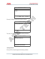
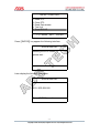
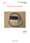
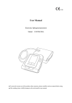
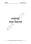
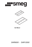
1
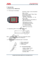
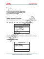
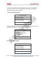
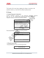
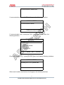
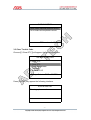
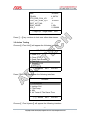
ADS5303
User manual
Dear user,
Thank you for purchasing ADS5303 (MOTO-SUZUKI). This manual contains
introduction, function, usage and after-sale, please read it carefully before
using.
CONTENT
I. Introduction ............................................................................................. 02
1.1 External view of mainframe ........................................................................ 02
1.1.1 Front layout of mainframe .......................................................................02
1.1.2 Operation guide for the top part of mainframe ....................................... 02
1.1.3 Operation guide for the bottom part of mainframe ................................. 02
1.2 Technical parameter ................................................................................. 02
II. Function ................................................................................................. 03
2.1 Mainframe power supply modes ............................................................... 03
2.2 Menu introduction of boot-strap ................................................................ 03
2.3 System diagnostic menu ........................................................................... 03
2.4 System information menu ......................................................................... 04
2.5 Software update menu .............................................................................. 04
III. Usage .................................................................................................... 05
3.1 System diagnostic introduction ................................................................. 05
3.2 Read trouble code .................................................................................... 05
3.3 Clear trouble code .................................................................................... 07
3.4 Read data stream ..................................................................................... 08
3.5 Action Testing ......................................................................................... 09
3.6 Read ECU ID ............................................................................................. 10
FAQ .................................................................................................................. 12
III. After-sale ................................................................................................ 12
-1-
I. Introduction
1.1 External View of Mainframe
1.1.1 Front layout of mainframe
Mainframe Length: 220mm Mainframe
Width: 150mm
Vision Screen Length: 104mm Vision
Screen Width: 81mm
Instruction of keyboard:
【ENTER】Confirmation to the
current option.
【EXIT】Negation to the problem or
return to the last menu.
【↑】Upward movement
【↓】Downward movement
【 → 】 Move forward
【 ← 】 Move backward
【RESET】 Function key
1.1.2 Operation guide for the top part of mainframe
Note: 1. Brightness adjusting knob of the Mainframe screen.
2. Power supply switch of the Mainframe.
1.1.3 Operation guide for the bottom part of mainframe
1. Power supply insert
2. Diagnose interface
3. USB interface
1.2
Technical Parameter
Working Voltage: DC12V
Working current: <1A
Working temperature: 0~40℃
Humidity: <80%
-2-
II. Function
2.1 Mainframe Power Supply Modes
MOTO-SUZUKI has several power supply modes:
1. Motorcycle diagnostic connector power supply.
2. A.C.transformer power supply
3. Provide electricity with USB interface, mainly used during the software
updating.
2.2 Menu Introduction of Boot-strap
After electrifying the mainframe, turn on the power supply. The mainframe
displays the application object of the scanner: MOTORCYCLE SCANNER.
After waiting for 1sec. It can enter the main menu automatically.
SUZUKI MOTOR
1.11..
System Diagnosis
m
s
m
2. System Informations
3. Software Updating
Select ENTER
The main menu displays the function menu of MOTO-SUZUKI. There are
three correlative function menus. As shown in the picture above, the black
item means the choosing item.
2.3 System Diagnosis Menu
d
d
C
SUZUKI MOTOR
C
1. System Diagnosis
2. System Information
3. Software Updating
Select ENTER
-3-
This menu is the main menu of this diagnostic scanner, all the diagnostic
functions enter from this menu. Because of its importance, we will give a
detailed description in the later section.
2.4 System Information Menu
SUZUKI MOTOR
1. System Diagnosis
2. System Information
3. Software Updating
Select ENTER
This menu displays some specific information of the diagnostic scanner. After
pressing the [ENTER] key, it appears the following interface.
System Information
MOTOR
System software:
03.00
d
C
Diagnostic software: 1.00
C
S/N:dOEM0001548
Press [ENTER] to confirm
2.5 Software Updating Menu
SUZUKI MOTOR
1. System Diagnosis
2. System Information
3. Software Updating
Select ENTER
-4-
This function will be used when updating the software. According to this
operation direction, you can finish the software update process.
III. Usage
3.1 System Diagnostic Introduction
Connect diagnostic connector to the motorcycle diagnostic connector
and turn on the ignition switch. Open the power supply switch of the
diagnostic scanner, and enter the following interface.
SUZUKI MOTOR
1. System Diagnosis
2. System Information
3. Software Updating
Select ENTER
Press the [ENTER] key to enter the following interface.
Diag.
1. SIEMENS SYSTEM
..
S
M
M
d SC
d
C
Select EXIT ENTER
3.2 Read Trouble Code
Press [ENTER] key to enter the following interface.
SUZUKI MOTOR
d
d
C
C
-5-
Communication, please wait...
If communication failure with ECU will appear the following interface.
SUZUKI MOTOR
Communication failure!
Press [ENTER] to confirm
If communication with motorcycle ECU is successful will enter the
followinginterface.
SELECT FUNCTION
.1. Read DTC
.2. Clear
d DTC
C
d
C stream
3. Read Data
4. Test Unit
5. Read ECU ID
↑→↓←Select
EXIT
ENTER
Choose【1.Read DTC】,press【ENTER】key it will display following interface.
SUZUKI MOTOR
Reading the DTCs, please wait...
d
d
C
C
When read trouble code finished it will appear the following interface.
-6-
SUZUKI MOTOR
P0105 Intake manifold pressure sensor
P0110 Intake air temperature sensor
DTC number:2
EXIT
3.3 Clear Trouble Code
Choose【2.Clear DTC】will appear the following interface.
SELECT FUNCTION
1. Read DTC
d
C
2. Clear DTC
d
C
3. Read Data stream
4. Test Unit
5. Read ECU ID
↑→↓←Select
EXIT
ENTER
Press [ENTER] key appear the following interface.
SUZUKI MOTOR
Clearing, please wait...
-7-
d
C
Later will appear the following interface.
SUZUKI MOTOR
Clearing has carried out!
Press [ENTER] to confirm
3.4 Read Data Stream
Choose【3.Read Data Stream】enter the following interface.
SELECT FUNCTION
1. Read DTC
d
C
2. Clear
DTC
d
C
3. Read Data stream
.4. Test
d Unita
m
.5. Read
d ECU
a ID m
↑→↓←Select
EXIT
ENTER
This function is used to display the current data condition of ECU system.
Using this data, you can estimate the vehicle working condition. Press
[ENTER]. After the guide information, it appears the following interface.
Data stream
-8-
AMP
CRASH
CTR_ERR_DYN_VR
CUR_IGC_DIAG_cyl1
DIST_ACT_MIL
ENG_HOUR
IGA_1
96.6kPa
4.9973V
0
0.0000V
0
1.50h
5.156699
←Page Up →Page Down
EXIT
Press【→】key continue to look over other data stream.
3.5 Action Testing
Choose【4.Test Unit】will appear the following interface.
SELECT FUNCTION
1. Read DTC
2. Clear DTC
3. Read Data stream
4. Test Unit
.5. Read
t ECU
t ID
.
t
t
↑→↓←Select
EXIT
ENTER
Press【ENTER】key appear the following interface.
Actuator
1. Fuel Injector
2. Ingition Coil
3. Fuel Pump
4. MIL
5. All Tests At The Same Time
↑→↓←Select
EXIT
ENTER
Choose【1.Fuel Injector】will appear the following interface.
-9-
.
1.50h
0.0000V
SELECT FUNCTION
1. ON
2. OFF
↑→↓←Select
EXIT
ENTER
Choose【1.ON】will appear the following interface.
SUZUKI MOTOR
Testing, please wait...
The carry out finished will display the following interface.
SUZUKI MOTOR
Test has carried out!
Press [ENTER] to confirm
3.6 Read ECU ID
Choose [5.Test Unit] will appear the following interface.
- 10 -
SELECT FUNCTION
1. Read DTC
2. Clear DTC
3. Read Data stream
4. Test Unit
5. Read ECU ID
↑→↓←Select
EXIT
ENTER
Press【ENTER】key appear the following interface.
SUZUKI MOTOR
Reading the ECU version,
please wait...
Later display the following information.
SUZUKI MOTOR
ECU VER:QG0100
Press [ENTER] to confirm
- 11 -
FAQ and solutions:
1. When testing the motorcycle ECU, it displays “Communication failure!”.
Pls check up whether the ignition switch turn on and whether the main test cable
is connected reliable.
2. After electrifying and turning on the device, it displays white screen or
black screen. Pls check up whether the powers supply voltage of the device is
normal and adjust the adjustable knob exa c t l y after re starting.
3. When the engine is working, pls make sure that the indoor is ventilation or
connect the exhaust gas equipment to the vehicle’s exhaust system.
4. Before use the device, pls make sure the motorcycle has been parked in a
stable state and don’t use the scanner during driving process.
5. When you operate the diagnostic scanner during the engine running, pls
keep enough distance from any running parts of the engine or the driving belt.
Because the running parts of engine or the driving belt may engulf
clothes, the connecting line of the diagnostic scanner or any part of the
Conner’s body to lead serious hurt.
6. Unless there is other operation direction, you must turn off the ignition switch
when connecting or removing the line of electronic circuit components.
7.When the engine is running, pls don’t touch the ignition coil, the ignition coil
terminals or the spark plug, which can produce very high voltage.
8. Although the diagnostic scanner has a safety design that the battery can
prevent from being connected reverse, but we still strongly remind you
must make sure the battery polarity before you connecting the scanner.
9. Never put the diagnostic scanner on the battery. Because it is
very likely to lead battery short-circuit, and cause personnel hurt, equipment
damage and vehicle trouble.
10. Don’t touch the exhaust, engine or radiator system when it is running or
just finished running. If you have to touch the hot parts, please wear the
tested heat-resistant gloves to avoid burn.
11. Don’t expose the scanner in the flammable gas or steam.
10. This diagnostic scanner belongs to precise electronic product, don’t
unweave or repair it by yourself.
12. If there is any change in the actual producing, we won’t give a prior notice.
IV. After-sale
1. Guarantee period: One year warranty.
2. URL:http://www.adsscan.com
3. Phone: +86-755-89368397
4. E-mail: [email protected]
- 12 -