1
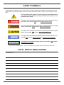
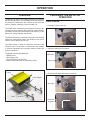
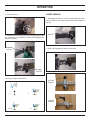
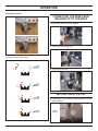
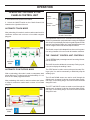
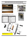
RW30110 RW30112 RW30120 ROBOTIC WELDER Safety, Operation and Maintenance USER'S MANUAL Copyright© The Stanley Works 2008 69893 4/2013 ver 6 TABLE OF CONTENTS SAFETY SYMBOLS................................................................................................................................................................................. 5 LOCAL SAFETY REGULATIONS............................................................................................................................................................ 5 SAFETY PRECAUTIONS......................................................................................................................................................................... 6 OPERATION........................................................................................................................................................................................... 11 OVERVIEW......................................................................................................................................................................................... 11 PREPARING THE RW30 FOR OPERATION..................................................................................................................................... 11 CLAW VERSION................................................................................................................................................................................ 11 CLAMP VERSION.............................................................................................................................................................................. 12 CONNECTING THE WIRE FEED/WELDING TIP TO THE RW30..................................................................................................... 13 SETTING THE STICK OUT................................................................................................................................................................ 13 OPERATING THE RW30 & THE CHARLIE CONTROL UNIT............................................................................................................ 14 INFORMATION ON DATA TRACKING............................................................................................................................................... 16 MANUAL DATA ENTRY...................................................................................................................................................................... 16 AUTOMATIC DATA ENTRY................................................................................................................................................................ 16 OPERATOR DIALOGUE.................................................................................................................................................................... 17 STOP AND RESTART OF WELDING CYCLE.................................................................................................................................... 20 ERROR MESSAGES.......................................................................................................................................................................... 20 EQUIPMENT MAINTENANCE & CARE................................................................................................................................................. 22 TROUBLESHOOTING........................................................................................................................................................................... 22 SPECIFICATIONS.................................................................................................................................................................................. 24 RW30 HEATER...................................................................................................................................................................................... 25 ACCESSORIES..................................................................................................................................................................................... 26 SPARE PARTS....................................................................................................................................................................................... 27 RW30110 / RW30112 PARTS LIST & ILLUSTRATION.......................................................................................................................... 29 RW30120 PARTS LIST & ILLUSTRATION............................................................................................................................................ 30 RW30110 / RW30112 / RW30120 LEFT SIDE ILLUSTRATION............................................................................................................. 31 RW30110 / RW30112 / RW30120 RIGHT SIDE ILLUSTRATION.......................................................................................................... 32 RW30110 / REW30112 / RW30120 MOTOR BOARD ILLUSTRATION................................................................................................. 33 RW30110 / RW30112 / RW30120 SUPPORT PLATFORM ILLUSTRATION......................................................................................... 34 RW30110 / RW30112 / RW30120 SUPPORT ASSEMBLY.................................................................................................................... 35 CLAMP ASSEMBLIES............................................................................................................................................................................ 36 TORCH SUPPORT................................................................................................................................................................................ 37 TORCH SUPPORT (PULL GUN)........................................................................................................................................................... 38 WARRANTY........................................................................................................................................................................................... 39 SERVICING THE STANLEY ROBOTIC WELDER: This manual contains safety, operation, and routine maintenance instructions. Stanley Hydraulic Tools recommends that servicing of hydraulic tools, other than routine maintenance, must be performed by an authorized and certified dealer. Please read the following warning. SERIOUS INJURY OR DEATH COULD RESULT FROM THE IMPROPER REPAIR OR SERVICE OF THIS TOOL. REPAIRS AND / OR SERVICE TO THIS TOOL MUST ONLY BE DONE BY AN AUTHORIZED AND CERTIFIED DEALER. MAKE NO ALTERATIONS OR MODIFICATIONS TO THE TOOL. SERIOUS INJURY COULD RESULT FROM IMPROPER CHANGES. MODIFICATIONS OR ALTERATIONS COULD ALTER THE PERFORMANCE OR INTEGRITY OF THE TOOL. IMPORTANT To fill out a Product Warranty Recording form, and for information on your warranty, visit Stanleyhydraulic.com and select the Warranty tab. (NOTE: The warranty recording form must be submitted to validate the warranty). 3 DECLARATION OF CONFORMITY ÜBEREINSTIMMUNGS-ERKLARUNG DECLARATION DE CONFORMITE CEE DECLARACION DE CONFORMIDAD DICHIARAZIONE DI CONFORMITA Hydraulic Tools ______________________________________________________________________ I, the undersigned: Ich, der Unterzeichnende: Je soussigné: El abajo firmante: lo sottoscritto: Weisbeck, Andy Surname and First names/Familiennname und Vornamen/Nom et prénom/Nombre y apellido/Cognome e nome hereby declare that the equipment specified hereunder: bestätige hiermit, daß erklaren Produkt genannten Werk oder Gerät: déclare que l’équipement visé ci-dessous: Por la presente declaro que el equipo se especifica a continuación: Dichiaro che le apparecchiature specificate di seguito: Robotic Welder 1. Category: Kategorie: Catégorie: Categoria: Categoria: 2. Make/Marke/Marque/Marca/Marca 3. Type/Typ/Type/Tipo/Tipo: 4. Serial number of equipment: Seriennummer des Geräts: Numéro de série de l’équipement: Numero de serie del equipo: Matricola dell´attrezzatura: Stanley RW30 All Has been manufactured in conformity with Wurde hergestellt in Übereinstimmung mit Est fabriqué conformément Ha sido fabricado de acuerdo con E’ stata costruita in conformitá con Directive/Standards Richtlinie/Standards Directives/Normes Directriz/Los Normas Direttiva/Norme CEE CEE CEE CEE CEE CEE CEE EN EN EN EN Machinery Directive No. Nr Numéro No n. 98/37/CEE:22/06/98 89/336/CEE:03/05/89 92/31/CEE:28/04/92 93/68/CEE:22/07/93 1999/5/CEE:09/03/99 73/23/CEE:19/02/73 93/68/CEE:22/07/93 60974/1:06/00 60974/1/1A:04/01 169:12/92 50199:01/97 2006/42/EC:2006 Approved body Prüfung durch Organisme agréé Aprobado Collaudato J. Sauron S.A. Self None 5. Special Provisions/Spezielle Bestimmungen/Dispositions particulières/Provisiones especiales/Disposizioni speciali: 6. Representative in the Union: Patrick Vervier, Stanley Dubuis 17-19, rue Jules Berthonneau-BP 3406 41034 Blois Cedex, France. Vertreter in der Union/Représentant dans l’union/Representante en la Union/Rappresentante presso l’Unione Done at/Ort/Fait à/Dado en/Fatto a Stanley Hydraulic Tools, Milwaukie, Oregon USA Signature/Unterschrift/Signature/Firma/Firma Position/Position/Fonction/Cargo/Posizione Engineering Manager 4 Date/Datum/le/Fecha/Data 6-22-11 SAFETY SYMBOLS Safety symbols and signal words, as shown below, are used to emphasize all operator, maintenance and repair actions which, if not strictly followed, could result in a life-threatening situation, bodily injury or damage to equipment. This is the safety alert symbol. It is used to alert you to potential personal injury hazards. Obey all safety messages that follow this symbol to avoid possible injury or death. This safety alert and signal word indicate an imminently hazardous situation which, if not avoided, will result in death or serious injury. This safety alert and signal word indicate a potentially hazardous situation which, if not avoided, could result in death or serious injury. This safety alert and signal word indicate a potentially hazardous situation which, if not avoided, may result in minor or moderate injury. This signal word indicates a potentially hazardous situation which, if not avoided, may result in property damage or damage to the equipment. This signal word indicates a situation which, if not avoided, may result in damage to the equipment. Always observe safety symbols. They are included for your safety and for the protection of the tool. LOCAL SAFETY REGULATIONS Enter any local safety regulations here. Keep these instructions in an area accessible to the operator and maintenance personnel. 5 SAFETY PRECAUTIONS Tool operators and maintenance personnel must always comply with the safety precautions given in this manual and on the stickers and tags attached to the tool and hose. These safety precautions are given for your safety. Review them carefully before operating the tool and before performing general maintenance or repairs. Supervising personnel should develop additional precautions relating to the specific work area and local safety regulations. If so, place the added precautions in the space provided on page 5. The RW30 Robotic Welder will provide safe and dependable service if operated in accordance with the instructions given in this manual. Read and understand this manual and any stickers and tags attached to the tool before operation. Failure to do so could result in personal injury or equipment damage. SHOCK HAZARD Contact with live electrical parts can cause fatal accidents or serious burns. The electrode work piece circuit is live when electricity is supplied to the outlet. The supply circuit and the internal circuits of the machine are also live when the current is switched on. When welding the wire, the feeder, the feeder control panel and any metal parts in contact with the wire are also live. Equipment that is incorrectly grounded constitutes a danger. • Do not touch any live part. • Wear insulated safety gloves that are both dry and without any holes, plus body protection. • Insulate yourself from the work piece and from the ground with appropriate insulation materiel to prevent any physical contact with either the work piece or the ground. • • Switch of the electricity supply or stop the machine before carrying out any maintenance on this machine. • • • Check the ground of the power supply regularly. Check that the ground wire of the mains cable is correctly connected to the ground terminal in the connection box or that the connector is connected to an output that is correctly grounded. • Switch off the machine when not in use. • • • • • Do not use cables that are worn, damaged, under dimensioned or badly spliced. Install and ground this machine correctly and in compliance with the instruction manual and with local, governmental or national legislation. When connecting the input, first connect the ground. Double check the connections. Check the state of the mains lead and the insulation of the wires regularly – replace the lead immediately if it is damaged as bare wires could cause fatal accidents. Do not wrap or carry cables around your body. If the work piece is to be grounded, ground it with a separate cable – do not use the clamp or the cable of the work piece. Do not touch the electrode if you are in contact with the work piece, the ground or another electrode of another machine. Only use properly maintained equipment. Repair or replace any damaged components immediately. Carry out 6 SAFETY PRECAUTIONS maintenance work on the machine according to the instructions manual. • Wear a safety harness when working above ground. • Anchor all panels and covers solidly. • Fix the cable to the work piece or work bench with a good metal-on-metal contact as near as possible to the construction. WELDING HAZARDS The RAYS OF THE ARC can burn the eyes and the skin, the NOISE can damage the ears, FLYING SLAG or SPARKS can damage the eyes. The welding arc produces intense visible and invisible rays (ultraviolet and infrared) which can burn the eyes and skin. The noise generated can damage the ears. Metal particle or slag are projected into the air when chipping, grinding and when joints are cooling. NOISE • Wear approved earplugs if the level of noise is high. RAYS FROM THE ARC • • • Wear a welding mask with an appropriate filter screen to protect your eyes and face while welding or watching (see standards EN 169). Wear approved eye-protection goggles that give lateral protection. Use screens or barriers to protect observers and ask others not to look at arc. Wear protective clothing made of appropriate fire-proof materiel and protective shoes. FUMES AND GASES Welding produces fumes and gases. Inhaling these substances can be damaging to your health. • • Avoid fumes. Do not inhale fumes. • If ventilation is insufficient, use an approved air respirator. • Read the safety recommendations concerning materials (MSDS) and the manufacturer’s instructions concerning metals, consumables, coverings, cleansers and degreasing agents. • • • Only work in confined places if is well ventilated or wearing an air respirator. Have a properly trained supervisor stand by. Welding fumes and gases can accumulate and starve the atmosphere of oxygen which can lead to fatal accidents. Check there is no danger in breathing the air. When working indoors, ventilate the area and / or use fumes evacuation equipment to evacuate welding fumes and gases. Do not weld in areas where others are degreasing, cleaning or spraying. Heat and arc rays can react with other vapors and form gases which are highly toxic or an irritant. Do not weld coated metals such as galvanized steel, lead or cadmium plated metal until the coating has been removed from the area to be welded. Make sure the area is well ventilated and, if necessary, wear an air respirator. 7 SAFETY PRECAUTIONS Coatings and the metals they contain can produce toxic fumes when welded. GAS CYLINDERS Cylinders of protective welding gas contain gas under pressure. If a cylinder is damaged, it can explode. As cylinders of gas are part of the welding environment, they should be handled with caution. • Protect gas cylinders from excessive heat, shock, slag, exposed flames, sparks from the welding arc. • Store cylinders upright in a stationary rack or cylinder holder so that they cannot fall over. • Keep cylinders away from welding circuits or any other electrical circuit. • Never place a welding torch on a gas cylinder. • • • • A welding electrode should never make contact with a gas cylinder. • • Keep the valve protection cap in place except when using or connecting the cylinder. Never weld a pressurised cylinder, there is a risk of explosion. Only use protective welding gas cylinders, regulators, hoses and fittings designed for this specific purpose, make sure they and associated items are in good condition. Do not stand in front of the gas outlet when opening the gas valve on a cylinder. Read and follow the instructions concerning the use of cylinders of compressed gas and associated equipment and the other publications listed in the safety standards. WELDING CAN CAUSE FIRE OR EXPLOSIONS Welding container-like objects such as tanks, drums or pipelines can cause such objects to burst. Sparks are projected from the welding arc. The projection of sparks, hot items and hot equipment can cause fire and burns. Accidental contact of the electrode with metal objects can cause sparks, explosions, overheating or fire. Before welding in such cases, check that there is no danger. • • • Protect yourself and others from the projection of sparks and hot metal. • Sparks and other hot welding matter can propagate from one area to another through small cracks and openings. • Check for any fire that may start and have a fire extinguisher to hand. • Do not weld container-like objects such as tanks, drums or pipelines unless they have been properly prepared. • Connect the cable to the work piece as near as possible to the welding area to avoid having to feed the current over long hazardous distances which could cause electrocution or fire. Do not weld in places where sparks can fall on flammable substances. Move flammable substances at least 10.7 metres/35 feet from the welding arc. If this is not possible, cover them carefully with approved protective covering. 8 SAFETY PRECAUTIONS • • • Do not use welding equipment to defrost frozen pipes. • Before welding, remove all flammable substances from your pockets such as matches or any type of lighter. When not in use, remove the rod from the electrode holder. Wear grease-free clothing such as leather gloves, a heavy shirt, hemless trousers, safety footwear and headgear. EXHAUST FUMES Exhaust fumes from the motor can cause fatal accidents. Motors emit toxic exhaust. • Use the equipment outdoors in an open and well ventilated area. • When using the equipment indoors, evacuate the exhaust fumes well away from any fresh air intake vents. MOTOR FUEL • Do not top up with fuel while smoking or when near a source of sparks or a naked flame. • Do not fill the tank to the brim – leave space for the fuel to expand. • Stop the motor and let it cool down before checking or topping up with fuel. • Do not spill fuel. If fuel spills, clean it up before starting the motor. MOVING ENGINE PARTS Moving engine parts such as fans, rotors and driving belts can cause serious hand injury. Articles of loose clothing can also get caught up in them. • Keep all trap doors, panels, properly in place or closed. • Only ask qualified personnel to remove the safety devices or other covers in order to carry out when necessary maintenance work or repairs. • To avoid the motor accidentally starting while carrying out maintenance work or repairs, disconnect the cable from the negative (-) terminal of the battery. • Keep hands, hair, loose clothing and tools away from engine parts. • After maintenance work or repairs, replace all trap doors, panels, covers and other protective devices before starting the motor. SPARKS Sparks can ignite BATTERY GASES and cause explosions, BATTERY ACID can cause burns to the eyes and skin. Batteries contain acid that give of explosive gases. • Always wear a protective screen over the face when working on the battery. • Stop the motor before connecting or disconnecting the cables from the battery terminals. • Avoid making sparks with tools while working on the batter Do not us welding equipment to other fast-starting equipment 9 SAFETY PRECAUTIONS • Respect the correct positive (+) and negative (-) terminal polarity of the battery. STEAM from HOT PRESSURISED COOLANTS cause burns to the eyes and skin. Only check the level of the coolant when the motor is cold to avoid being scalded. • When the motor is hot and it is coolant, follow the next two steps. • • Wear protective eyeglasses and gloves and place a cloth over the cap. Turn the cap slightly to release the pressure slowly. Allow the pressure to decrease completely before removing the cap. Avoid making sparks with tools while working. Moving engine parts can cause bodily injury. Before working on the generator, remove the spark plugs or fuel injectors to prevent the motor from accidentally starting. Block the flywheel while working on the generator. Metal and dirt particles can cause injury to the eyes. Wear safety glasses that also offer lateral protection. Static Electricity can damage the components on the electric board. Before manipulating cards or other components, connect an earth wire to the earth terminal. Use antistatic packing material for storing, moving or transporting PC cards. Magnetic fields created by high voltage can interfere with the workings of pacemakers. Pacemaker wearers should keep their distance. Pacemaker wearers should first consult their doctor before going near any place where welding operations are being carried out. Read the instructions. Only use original spare parts. Replace the fuel injectors and the fuel system air bleeder as indicated in the motor instruction manual. MAKE SURE SPARKS FROM THE ENGINE EXHAUST DO NOT START A FIRE 1. Use an approved spark arrester on the motor exhaust wherever or whenever required – check the legislation in vigour. LOW VOLTAGE AND FREQUENCIES can damage electrical equipment such as motors. 1. Switch off or disconnect the equipment before starting or stopping the motor. EXCESSIVE WEAR can cause EQUIPMENT TO OVERHEAT. 1. Allow time for equipment to cool. 2. Reduce the current or operating cycle before restarting to weld. 3. Respect the rated operating cycle. 10 OPERATION PREPARING THE RW30 FOR OPERATION OVERVIEW The RW30 is an electric arc welding controller to be used for gas-free sheathed wires. It is unbeatable on railroad worksites for performing maintenance and repairs on rails and track devices, railways, tramways, metros, shuttles, etc. CLAW VERSION 1. Position the claw on the rail. The RW30 after programming automatically executes the reloading of worn sections and accidental surface defects (on treads, rail butt joints, lateral wears, track devices), or the deposits of “safety stainless steel beads”. The RW30 controls the motorized movement of the welding head in the X-axis (length) and Y-axis (width) for work over a surface area of 400 mm by 350 mm. The RW30 frame is made of composites, aluminum and stainless steel. This principle of construction was retained to combine lightweight and excellent behavior under bad weather conditions. 2. Adjust the sliding jaw and tighten. The RW30 is sold as standard with : -1 RW30 Frame -1 Rail Gripping Set -1 Torch Support for the Pull Gun -1 Charlie Control Box with its Connecting Cable Adjustment Tighten Frame 3. Check the jaw angle and reference supports. Torch Support Jaw Angle Rack Reference Supports 11 OPERATION 4. Set anti-slip bolt. CLAMP VERSION 1. Disengage the stop pin on the mounting bracket, insert the rack, adjust to one of the three positions and engage the stop pin. Disengage Stop Pin 5. Assemble the mounting brackets by disengaging the stop pin, inserting the two brackets together and engaging the stop pin to secure. Disengage Stop Pin 2. Slide in and engage the stop pin to the rack. Engage Stop Pin Heel Jaw in the Fixed Position Summary of Steps shown above. 1. 2. Heel Jaw in the Mobile Position 3. & 4. 5. 12 OPERATION Adjusting the Clamp CONNECTING THE WIRE FEED/ WELDING TIP TO THE RW30 1. Place the welding tip into the support. 2. Support swivel blocking lever. Summary of steps shown above. 3. Support stick-out lever. SETTING THE STICK OUT The ideal setting is 30 mm. Use the template markers to check for proper distance. 30 mm Ideal Setting 13 OPERATION OPERATING THE RW30 & THE CHARLIE CONTROL UNIT Display Screen 1. Turn ON the main switch on the RW30. 2. Unlock the ON/OFF switch on the Charlie Control Unit located on the right side of the unit. Valid Button Direction Arrows Stop/Reset Button AUTOMATIC TRACK MODE After preheating, this mode is used on carbon steel track for continuous surface work on three or four-sided octagonal polygons. Charlie Control Unit A computerised control unit to command the welding cycle, Charlie® is presented in a polycarbonate-housing unit equipped with a liquid crystal display and a six-keypad keyboard under lexan for man-machine dialog. Its 5 metre shielded mains cord can be wrapped around its tubular-shaped chassis. The Charlie® control unit is adapted for on-site work. Its protection rating classifies it for uses under all weather conditions. THE “CHARLIE” CONTROL UNIT CONTROLS The SCREEN displays messages as well as tracing information for the user. Rail Automatic Mode The VALID is used to validate the current step. During a cycle, it is used to display the welding U and I. AUTOMATIC POINTS/FROG MODE The STOP button is used to return to the previous step. During a cycle, it is used to momentarily or definitively stop the welding cycle. With no preheating, this mode is used on manganese steel points and frogs. For strip-by-strip work alternately of 1 to 3 three or four-sided polygonal surfaces. The UP and DOWN arrows are used to scroll through the alphanumeric character list during the tracing data acquisition stage. In the setting stage, it is used to move the head along the Y-axis. After preheating, this mode is used on carbon steel points or frogs for continuous surface work on three or four-sided polygons. The LEFT and RIGHT arrows are used to scroll through the alphanumeric character list during the tracing data acquisition stage. In the setting stage, it is used to move the head along the X-axis. Crossing Automatic Mode 14 TRANSLAMATIC RW30 OPERATION J.SAURON areexamples screen examples of scrolling through thealphanumeric alphanumeric character list.list 3.1 Below Screen of scrolling through the character In tracing mode A--------- - B--------- - C--------- - B---------- A---------- -_--------- --_-------- -_ --------- --_-------- Examples: scrolling up the list C---------- Examples: scrolling down the list _---------- Examples: moving the cursor from left to right _---------- Examples: moving the cursor from right to left LINE - - ------ PK - - VALID -- VALID TRACK DATA ---------- Examples: moving forward through the operator dialogue TRACK DATA ---------- STOP PK - - -- STOP LINE - - --- --- Examples : moving back through the operator dialogue In welding mode WELDING CYCLE BEAD XX/XX STOP STOP CYCLE RESTART CYCLE ? VALID RESTART WELDING CYCLE Example: momentary stop in the welding cycle WELDING CYCLE BEAD XX/XX STOP STOP CYCLE RESTART CYCLE ? STOP END LAYER N° X LAYER N° Y VALID Example: definitive stop in the welding cycle 08 JS 063* du 17/12/2008 15 02/04/2009 PAGE : 6/68 OPERATION INFORMATION ON DATA TRACKING LANGUAGE SETTING Different languages may be accessed and selected when the first message “HELLO” appears by using the PLUS key. Translations of the message “HELLO” into different languages according to geographic areas are then displayed each time the PLUS key is pressed. MANUAL DATA ENTRY Some areas may require manual data entry: SETTING THE DATE AND TIME To set the date and time, scroll until “DATE AND TIME” is displayed. Set the date and time by pressing the PLUS or MINUS keys. Confirm using the VALID key. • Operator stamp • Location, district code, line, mileage point, track and rail line • Type of metal deposition • Type of power source • Type of rail • Type of resurfacing. Depending on how the unit is configured, the “DATE TIME” message may not be displayed if the most succinct level of operator dialogue is used. Two types of manual entries are possible: PRINTING DATA To print the data stored in memory: Pressing the PLUS or MINUS keys causes the allowable characters to be displayed each character is confirmed by the VALID key. 1. Make sure that the unit is connected to a power source. 2. Pre-programmed values. 2. Connect either a serial printer (9-pin connector) or a parallel printer if the unit is equipped with a parallel interface (25-pin connector). Pressing the PLUS or MINUS keys causes the various preprogrammed values to be displayed. Each value is then confirmed by pressing the VALID key. When the characters “----” appear, this indicates characters available for manual character-by-character entry. 1. Character by character mode. When using a serial printer, make sure: 1. that the serial printer communication parameters are set correctly: • 9600 bauds • no parity • 8 data bits • 1 stop bit AUTOMATIC DATA ENTRY Data can also be acquired by reading bar codes. Depending on the software installed in the unit and according to the user companies’ specifications, data may be acquired automatically. Depending on these specifications, data may be required or optional. 2. that the correct serial cable is used. 3. Make sure the printer is ONLINE and READY. The software includes a standard operator description card with a 30-digit ISO bar code. 4. Turn on the unit and scroll to the IMPRESSION step, available by the automatic detection by the system of the presence of a printer. 5. Select the output mode: • Welding number • Operator ID • Date • All 6. Confirm choice using the VALID key. 16 OPERATION Validate by pressing: OPERATOR DIALOGUE Power up: Corrections can be made by pressing: Memories Test Then: ALIGNMENT OK HELLO Change language - press the arrows: Note: This is also effective during all welding cycle. To go to the next step, press: or CTRL.PROG x.xxx CHARLIE Nxxxxxxx To step back to the previous step, press: Display software version and Charlie serial number. NO ALIGNMENT SPEED cm/mn This mode allows to perform free polygons from 3 to 4 sides. • Setting the points without restriction (beads direction : Position O1 to Position O2). : 30 Welding speed displayed cm/min (1 cm/min equals to 0.4 inch/min) (adjustable value in the parameter menu). • When setting the 4 points, point 4 can be out of the vertical alignment of point Position O1; without automatic control of any alignment. Allow to move the torch according into 2 axis « X » et « Z ». • Welding mode « bead by bead ». LAYER 1 TORCH: PO1 ALIGNMENT OK Set point Position O1. Define the resurfacing area. Simple welding mode: Shapes like rectangle, triangle and butt welding. TORCH: PO2 • Non stop welding our bead by bead. Set point Position O2. The torch cans only moves on the « X » axis. • Realization with or without surrounding. Changing welding modes by pressing: or TORCH: 17 PO3 OPERATION Display of the step between each bead, (distance in mm, 1 mm equals to 0.04 inch) and estimate welding time in minutes. Set point Position O3. The torch cans only moves on the « Z » axis. TORCH: BEADS 1 BY 1 ? YES - VALID PO4 or TORCH: BEADS 1 BY 1 ? NO - VALID PO4 Welding mode choice: bead by bead, « YES », or continue, « NO ». or TORCH: PO4 If « YES », welding bead by bead (Torch is moving at the beginning of the next bead right after previous bead is done). Set point Position O4. This point should only be set vertically from point Position O1 with automatic tone of this position. If « NO », beads are done in “continue”. WELDING CYCLE VALID LENGTH: xxmm WIDTH: xxmm If VALID key is pressed, Torch will move to starting point of Position O1. Welding will start. Display the length and the width of the setting shape (1 mm equals to 0.04 inch). While welding: SURROUND ? YES - VALID RETURN TORCH TO INITIAL POINT SURROUND ? NO - VALID Torch moves to starting point of the welding or at the beginning of the new bead if “bead by bead” mode has been selected. WELDING CYCLE SURROUND Surrounding selection: « YES », or « NO », (continuing bead from Position O1 to Position O2 then to Position O3 then to Position O4 and finally to Position O1). Surrounding welding if that option has been selected. NUMBER BEADS: xx WELDING CYCLE BEAD xxx/yyy Display the number of beads that will be made during the resurfacing (the surrounding is not included in this number). It is possible to modify this number if needed by pressing: Shows the bead’s number in welding, « xxx », and the total number of beads of the whole resurfacing of the area, «yyy». or If « bead by bead » option is selected, the following screen appears at the end of the previous bead and after the torch is set. SPACING: x.xx mm WELD.TIME: xxmin VALID TO START FOLLOWING BEAD 18 OPERATION If VALID key is pressed, torch will move to the starting point of the next bead. RETRACTING POINT RETURN TORCH TO INITIAL POINT Selection of Torch position after the welding of each bead (evacuation point). Torch return to starting point and start welding of the next bead. The setting is done as: END LAYER N : 1 LAYER N : 2 - VAL TORCH: Set point position O1. When resurfacing is over, the following message proposes to set a new resurfacing cycle: TORCH: If VALID key is pressed, you will have to set a new welding area. (As previously seen). PO2 Set point position O2. If RESET key is pressed: NEUTRAL POINT ? TRANSPORT - VALID TORCH: PO3 Set point position O3. Allow to place the torch in « Parking » position. TRIANGLE ? NO - VALID If VALID key is pressed, torch will move to « Parking » position. or If RESET key is pressed, back to message: TRIANGLE ? YES - VALID HELLO Triangle can be weld: if « NO », set point Position O4. If « YES », needed number of beads will be display. NO ALIGNMENT TORCH: Note: This is also effective during all welding cycle. PO4 Set point position O4. To go to the next step press the VALID key. NUMBER BEADS: xx To step back to the previous, press the RESET key. SPEED cm/mn PO1 : 30 Display the number of beads that will be made during the resurfacing (the surrounding is not included in this number). It is possible to modify this number if needed by pressing: Welding speed displayed cm/min (1 cm/min equals to 0.4 inch/min) (adjustable value in the parameter menu). or 19 OPERATION If RESET key is pressed: SPACING : x.xx mm WELD.TIME : xxmin NEUTRAL POINT ? TRANSPORT - VALID Display of the step between each bead, (distance in mm, 1 mm equals to 0.04 inch) and estimate welding time in minutes. Allow to place the torch in « Parking » position. -Setting can be made up to 3 shapes: If VALID key is pressed, torch will move to « Parking » position. SETTING SHAPE X ? NO - VALID If RESET key is pressed, back to message: HELLO SETTING SHAPE X ? YES - VALID STOP AND RESTART OF WELDING CYCLE Option to repeat the same shape or change the size and shape as previously indicated. During the welding, in whatever mode you have selected, stopping the welding cycle is always possible: During welding: Pressing the RESET key will stop the weld cycle. STOP CYCLE RESTART CYCLE ? RETURN TORCH TO INITIAL POINT To restart the welding cycle, press VALID key. Torch moves to starting point of the first bead. WELDING CYCLE BEAD xxx/yyy According to what mode you are using, a correction of the exact positioning of the torch during the stopping can be done: Shows the bead’s number in welding, « xxx », and the total number of beads of the whole resurfacing of the area, «yyy». -Maximum correction: 1 cm following the 2 axis « X » and « Z» To stop the welding cycle, press the RESET key. MOVE TORCH ERROR MESSAGES During the setting of the points, some errors message can appear: Torch will moves to retracting point after bead. VALID TO START FOLLOWING BEAD Set Position O2: MIN LEN : 30mm ! LENGTH : xx mm Press VALID key to start the next bead. END LAYER N : 1 LAYER N : 2 - VAL The distance between points Position O1 and Position O2 must be minimum or equal to 30mm on « X » axis. (This message will be displayed only if the distance between Position O1 and Position O2 < 30mm). Note : this distance (30mm equals to 1.18 inch) is set in the parameters menu. If VALID key is pressed, you will have to set anew welding area. (As previously seen). 20 OPERATION Set Position O4: -In mode « ALIGNMENT OK » UNVALID POINT RETURN TO PO1 Position O4 must be vertical from Position O1. When the beads number has been modified: ERROR !!! SPACING > xx.x mm The step is bigger than the maximum allowed step. Raise the number of beads. ERROR !!! SPACING < xx.x mm The step is smaller than the minimal allowed step. Reduce the number of beads. These 2 values can be modified in the parameters menu. ERROR BEADS NUMBER > 3 The number of beads must be superior at 3. DIV ERROR Show an inappropriate calculation not allow by the software. 21 J.SAURON 6 TROUBLE SHOOTING TRANSLAMATIC RW30 TROUBLESHOOTING The « ON » TRANSLAMATIC‘s green light does not work PROBABLE CAUSE CHECKS AND REMEDYS « ON/OFF » switch Check its good position and its good working order Alimentation’s cable cutted Check the alimentation’s cable Alimentation’s plug Check the alimentation’s plug Alimentation’s fuse or circuit breaker Check the primary alimentation The « ON » TRANSLAMATIC‘s green light works but the Charlie box does not work PROBABLE CAUSE CHECKS AND REMEDYS Link cable between the TRANSLAMATIC and Check the connexions or/and change the cable the Charlie box Charlie box’s fuse Check the fuse Respect the « ON »process order Put « ON » the Translamatic before putting the Charlie box “ON”. Charlie box Try with another Charlie box Interface card Check if the interface card alimentation’s green light is alight during the cycle. Call our After Sales Dpt Stabilized alimentation out of service Check the alimentation’s tension, normally 27V in CC. Call our After Sales Dpt The welding support head does not move on one or several axis PROBABLE CAUSE CHECKS AND REMEDYS Charlie box Try with another Charlie box Charlie box keyboard Check the good working order of the keyboard’s contacts. Check the good working order of the keyboard using it in the test mode for example. Call our After Sales Dpt Interface card Check the connexions Check if the card’s lights are alight during a moving command. Call our After Sales Dpt Axis engine’s cards Check if the card’s lights are alight during a moving command. Switch the connexions between the 2 engines and the recheck the moving of the torch (the movements are reversed) Call our After Sales Dpt Translation’s screw mechanically blocked Check if the screw is not top-blocked on the stop bumpers or on the ball bearing or on the cardan. Unscrew manually the screw if it is possible. Call our After Sales Dpt Uncontrolled speed of the torch and/or no high speed and/or speed not as usual. PROBABLE CAUSE CHECKS AND REMEDYS Charlie box Try with another Charlie box Change the Charlie box card 08 JS 063* du 17/12/2008 02/04/2009 22 PAGE : 8/68 J.SAURON TROUBLESHOOTING TRANSLAMATIC RW30 Coder’s pulses defect Check the coder connexion on the right side and on the bottom of the interface card (J3 connector side). Replace the interface card. Axis engine’s cards Check if the card’s lights are alight during a moving command. Switch the connexions between the 2 engines and the recheck the moving of the torch (the movements are reversed) Call our After Sales Dpt Interface card Check all the connexions Check if the card’s lights are alight during a moving command. Replace the interface card Call our After Sales Dpt Couple Engine + Coder. Replace the couple Engine + Coder. No wire feeding PROBABLE CAUSE CHECKS AND REMEDYS The PGA Close or set up the wire’s pressure with the PGA’s rollers. The Roll n’ Roll Check the wire’s drum and/or set the Roll n’ Roll brake Cables Check the connexions and the PGA‘s alimentation cable Charlie box Try with another Charlie box Check if the welding command light is alight on the interface card Link cable between the TRANSLAMATIC and Check the connexions or/and change the cable the Charlie box Welding trigger opened (Welding control Check the closing of the welding trigger with an connector) ohmeter (value < to 20 ohms) between the pins 3 and 4 of the 7 points connector or C an D of the Amphenol connector 19 points. Stabilized alimentation out of service Check the alimentation’s tension, normally 27V in CC. Call our After Sales Dpt Wire feeding OK but no welding PROBABLE CAUSE CHECKS AND REMEDYS Ground cable Make sure that the ground cable is well connected Interface card Check if the card’s lights are alight during a moving command. Call our After Sales Dpt Arc welder generator Check the parameters and the good operating of the arc welder Call our After Sales Dpt FOR ANY INTERNAL INTERVENTION OUT OF THESE POINTS ABOVE, THANKS TO CALL OUR AFTER SALES DEPARTMENT 23 SPECIFICATIONS RW30110 / RW30112 Power........................................................................................................................................................115V, 60Hz, 175W X Axis Movement.........................................................................................................................................400 mm / 15.7 in. Y Axis Movement.........................................................................................................................................350 mm / 13.7 in. Length.........................................................................................................................................................925 mm / 36.4 in. Width...........................................................................................................................................................650 mm / 25.5 in. Height..........................................................................................................................................................440 mm / 17.3 in. Weight...............................................................................................................................................................25 kg / 55 lbs Charlie Control Box Weight (with 5m of cable)................................................................................................... 3 kg / 6.6 lbs Pull Gun Weight (without wire reel)................................................................................................................ 12 kg / 26.4 lbs RW30120 Power....................................................................................................................................................... 230V, 60Hz, 150W X Axis Movement.......................................................................................................................................1250 mm / 49.2 in. Y Axis Movement.........................................................................................................................................350 mm / 13.7 in. Length.......................................................................................................................................................1510 mm / 59.4 in. Width...........................................................................................................................................................830 mm / 32.6 in. Height..........................................................................................................................................................430 mm / 16.9 in. Weight............................................................................................................................................................34 kg / 74.9 lbs Charlie Control Box Weight (with 5m of cable)................................................................................................... 3 kg / 6.6 lbs Pull Gun Weight (without wire reel)................................................................................................................ 17 kg / 37.4 lbs NOTICE In addition to the Safety Precautions in this manual, observe the following for equipment protection and care. • Check that the pin holder is not burnt or not holding the pin tightly. If not, remove the ring holder, clean all the parts and squeeze the fingers of the pin holder together. • Check the cables on the gun from time to time for damage. Replace as required. • Check that the lift level is correct with lift level tool. • Always store the tool in a clean dry space, safe from damage or pilferage. • Always keep critical equipment markings, such as warning stickers and tags legible. • Equipment repair should be performed by experienced personnel only. • Do not use the equipment for applications for which it was not intended. 24 RW30 HEATER INSTALLED 2009 OR EARLIER Heater Element Thermostat Front Cover Back Cover Charlie Heater 70722 RW30 COLD WEATHER UPDATE KIT (70716) INCLUDES THE FOLLOWING Part No. Description 70719 Heater Element (110 V, 400 W) 70720 Thermostat (Red) 70718 Back Cover 70717 Front Cover 70721 Screw Kit 70722 Charlie Heater Kit 70723 Butt End Flask 71000 Thermostat (Blue) Heater Element Thermostats (Red & Blue) See parts illustrations for heaters installed on units built in 2010 or later. 25 ACCESSORIES Part No. Description Part No. Description 52736 Cable - Welder, Robotic 69823 Roll Un Roll Drum Holder 52737 Kit - Track Wheel, Robotic 69824 Blue bag for Charlie 52738 Kit - Track Wheel Welder, Robotic 69827 52739 Wire - Coated Weld Std Rail Male base, 6 P + gnd (wire feeder electrical conn) 52740 Wire - Coated Weld Mn Rail 69828 Plug for Male Base (Protective) 52741 Box - Transport 69832 Male base, 3 P + gnd (power cord) 60872 15m Ground Cable 69822 Adaption Box 60875 Ground Clamp for Frog 60876 Ground Clamp for Rail 60822 Cable, Generator 15M Long (Europe) 60823 Cable, Generator 15M Long (Miller) 60824 Transport Box RW20110, USA 60825 Transport Box RW20120, USA 60826 Tracability Kit 62328 Carbon Frog Insert 62350 Angle Attachment 62386 1/16 in. / 1.6 mm Frog Build Wire 62387 1/16 in. / 1.6 mm Rail Build Wire 65439 Welding Cable (Negative 15 M) 65441 Welding Cable (Positive 15 M) 67090 Pre-Heater (Carbon Steel Frogs) 69835 PGA Power Supply Cable (Pull Gun) 69833 Lincoln (HD), Wire Feed Cable 69836 Screen for Charlie 65443 Pull Gun Head 65444 Torch 4 M 65447 Kit 65449 Stick Out Gauge 65450 Serial & Parallel Option 65451 Stick Holder 65452 Rotary Head Kit 65453 Pre-Heater Ramp 65457 Welding Current Kit 66642 Pull Gun 66643 Inverter 66644 Torch 66766 Tool Case (with Tools) 66767 Glasses 66768 Mask, Automatic Darkening 66769 Mask, Manual 69889 Charlie Main Board 66773 Cable, 10 M (Generator to Robot) 67090 Pre-Heater (Carbon Steel Frogs) Part No. Description Cables - RW30110BN Only 68208 Charlie to Robot Cable (All Models) 68209 Power Cable (RW30110BN Only) 68210 Wire Feed Cable (Miller, Lincoln) (RW30110BN Only) 68211 Wire Feed Cable (0X0) (RW30110BN Only) RW30110 / RW30112 / RW30120 Models Only 26 65445 Wire Feed Cable 65442 Power Cable without End Plug 68208 Charlie to Robot Cable SPARE PARTS Trigger Cord 70780 Charlie Box 65446 Power Cord Primary 70781 Charlie Main Board 69889 Rack 66551 (Includes Pinion Below) Interconnection Board 64969 Pinion 66551 (Includes Rack above) Motor Board 64961 Motor/Board Cable 70786 Power Supply 69830 PGA Cable 70787 No/Off Switch 69831 Charlie Cable 68208 Motor X 64963 Power Supply Cord 70785 Y axis Motor Y 64962 Power Supply Cord 70784 X Axis Power Cord LED 70782 Power Supply Cord 70783 Internal Charlie Box Fuse 70774 27 SPARE PARTS Bearing Y Axis 66533 Pad Clamp 70775 Bearing X Axis 64950 Coupling, Y Axis 66535 Nut 66529 Power Cable (115V) 68209 Male Crosspin Knob M10-45 73158 Beam, Souriau 70779 No Photo TEMPLATE GUAGE Template guage for setting the stick height (see page 13). Template guage with 4 height settings indicated in milimeters and inches. Removing wire feed tip using hex in template guage. MASTER POWER SWITCH 2009 OR EARLIER Master Power Switch Off Master Power Switch On, this picture indicates the fan is on but the outside ambient temperature is below -10°C/14°F, allow the unit to warm-up until the left power light comes on indicating the unit is safe to use. Do not operate the unit when the left power light is off with the power switch turned on. Master Power Switch and Fan On. MASTER POWER SWITCH 2010 OR LATER Master Switch OFF Power is On Heater Activated Unit On Heater Activated 28 Unit On Heater Off RW30110 / RW30112 PARTS LIST & ILLUSTRATION Item Part No. Qty Description Item Part No. Qty 1 64983 1 Rear Beam 12 64988 1 Cover 2 64984 1 Front Beam 13 69818 1 Left Side Assembly 3 71473 1 Ventilation Box 14 69819 1 Right Side Assembly 4 66530 1 X-Axis Slide 5 66526 1 X-Axis Screw 15 69816 1 Support Platform Assembly 6 --- -- --- 16 66543 1 Left Support 7 66529 1 Nut 17 66542 1 Right Support 8 66535 1 Coupling Y-Axis 9 66536 1 Chain Conduit 18 69815 1 Torch Support Assembly 66537 1 Clamp for Chain Conduite (not show) 19 66546 2 Frog clamp Assy 20 ----- -- --------- 10 70718 1 Back Cover 21 ----- -- --------- 11 70717 1 Front Cover 22 ----- -- --------- 23 70719 1 Heater Element 24 ----- -- --------- 25 ----- -- --------- 26 ----- -- --------- 27 ----- -- --------- 28 ----- -- --------- 29 ----- -- --------- 29 Description RW30120 PARTS LIST & ILLUSTRATION 9 5 7 11 1 11 8 4 3 10 2 Item Part No. Qty Description 1 66515 1 Rear Beam 2 66519 1 Front Beam 3 66517 1 Protection Plate 4 66531 1 X-Axis Slide 5 66528 1 X-Axis Screw 6 --- -- --- 7 66529 1 Nut 8 66535 1 Coupling Y-Axis 9 66536 1 Chain Conduit 10 66537 1 Clamp for Chain Conduite (not show) 11 66554 1 Hood 1252 30 Heater 23 Raising item M/F M435 24 item 25 RW30110Isolating / RW30112 / RW30120 Isolating item (push) 26 Screw TBHC M410 27 Washer MU N6 28 Left Side Assembly Isolating 29 PartCap No. 69818 27 24 1 4 4 4 4 4 4 LEFT SIDE ILLUSTRATION 30 31 APG11980001 APG01120144 ATC03920059 ATC03920059 ATC01120233 APG01120296 ATC09600002 32 33 34 28 29 22 23 19 18 25 2 26 20 21 3 4 17 27 Item 1 2 3 4 5 6 7 8 9 10 11 12 13 14 15 16 14 13 12 11 15 1 Part No. Qty Description 1 66524Engine side 1 Left Side Plate (Motor) Engine cards unit (X,Y and Interface) 2 69817 1 Motor Card Module Conic Stop Bumper 3 64945 1 Conical Stop Engine side end stop 4 Screw FHC M410 ( DIN 7991 ) 5 Engine Ball Bearing 6 64959 1 XBearing Flange Engine Coder 7 934 )X Axis 8 64963Nut HM51( DINMotor Flat slice M3 9 Nut HM3 10 Rounded head Screw TBHC M820 11 X engine support 12 Screw 1364957Rounded head 1 Motor TBHC SupportM416 Male plug 3P+T 14 Rounded head Screw TC fendue M316 15 Rounded head Screw TBHC M516 16 Charlie plug 17 8 Item 16 17 18 19 20 21 22 23 24 25 26 27 28 29 30 10 9 Part No. TAF12500013 TAF12500015 69826 APT05630000 ATC20460019 APG01120149 ATC08490037 ATC08660014 APG02140092 69831 APT02140014 APG02140016 APG01120226 ATC08490035 ATC01120177 72593 ATC01100033 APG02140176 ATC01120182 ATC01100000 7 6 5 Qty Description 1 1 1 Charlie box take off 1 1 Aluminium 2 Aluminium 1 1 2 1 Power On/Off 2 Switch 2 2 Inox 1 Aluminium 2 Assy InoxCarry Handle 2 (Fold Down) 1 2 Inox 2 Inox 1 Aluminium 31 08 JS 063 C du 03/12/2009 32 21/12/2009 31 PAGE : 59/72 33 70720 1 Thermostat (Red) 34 71000 1 Thermostat (Blue) 28 29 30 31 RW30110 Flat slice M14 ( NFE 25 513 ) Flat slice M14 ( DIN 6798 ) Nut HM14 ( DIN 934 ) Orange light 10 mm APG01120036 APG01120326 APG01120200 ATC05060108 2 2 2 1 / RW30112 / RW30120 RIGHT SIDE ILLUSTRATION 12 14 15 13 1 7 2 11 17 16 15 10 9 5 6 18 8 4 3 14 13 7 Right Side Assembly Part No. 69819 Ball bearing side 1 Alimentation (27V) 2 Item Part Qty headDescription Screw HC M516( ISO 7380 ) 3 No.Rounded 1 1 location Right Side Plate 466525 Ball bearing Ball bearing 569830 2 1 Power Supply Rounded head Screw HC M816( ISO 7380 ) 6 3 764956 Handle of 4 1 bearing Bearing Support Isolating head 8 5 64955 1 Bearing Rounded & cutted head screw M416(DIN84) 9 6 7 72593 2 64945 1 Carry Handle Assy (Fold Down) 08 JS 063 C du 03/12/2009 21/12/2009 8 9 10 11 12 13 14 15 16 17 18 Conical Stop 32 TAF12500012 ATC05060055 APG01120182 ATC08490030 ATC05630004 APG01120181 ATC01320001 ATC09600002 APG01120295 Aluminium Aluminium 1 1 2 1 1 1 2 4 4 PAGE : 60/72 RW30110 / REW30112 / RW30120 MOTOR BOARD ILLUSTRATION Motor Board Assembly Part No. 69817 Item D-1 D-2 D-3 D-4 D-5 D-6 D-7 D-8 D-9 D-10 Designation Axis card Item Part No. Interconnection card 1 64961 Interconnection card bundle 64969 Screw CHC2M4-10 ( DIN 912 ) Nut H-M4 ( DIN 934 ) Star washer M4 ( DIN 6798 ) Column F/F M4-15 Column M/F M4-15 Nylon washer M4 Column M/F M4-35 Reference Qty 2 1 33 ATC08660012 Description TAF00000001 Motor Board TAF00000023 Interconnection APG01120412Board APG02140092 APT01120002 APG01120355 APG01120378 APG01120261 APG01120144 Material Qty 2 1 1 2 1 3 2 1 6 3 RW30110 / RW30112 / RW30120 J.SAURONSUPPORT PLATFORM ILLUSTRATION TRANSLAMATIC RW30 6 11 19 12 8 17 17 21 13 7 32 27 9 Partmobil No. Plateau 15 31 26 16 5 32 3 4 33 29 Désignation Qty 10 24 25 2 1 22 14 15 28 Repère Item 1 21 32 43 54 65 76 87 98 10 9 11 10 12 11 13 12 14 13 15 14 16 15 17 16 18 17 19 20 33 21 22 23 20 5 18 Description 64986 Support Platform Fixation Moteur Y 1 Rail Y ------Equerre Support Torche 64985 1 Y-Rail Logement Roulement 66549 1 Jointed Wrist Bracket Motoréducteur Codeur 66532 1 Y Bearing Support Maintien de roulement Réducteur 64962 1 Moto Y-Axis Motor Vis roulée double filets Y 64959 1 Bearing Flange Flasque Ecrou Vis Y 66534 1 Y-Axis Screw Ecrou PTFE 64958 1 Axis Bracket Butée Y 66529 1 Nut Cardan Croisillon 66538 1 Y-Bump Stop Galet acier 66535 Coupling Y-Axis Axe cylindrique ø121 64948 4 Steel Roller Axe excentrique ø12-1 64949 2 Axle Roulement 2 Ecentric Axle Butée64950 conique 66533 Bearing Vis HC tête bombée 1M8-20 ( ISO 7380 ) Vis FHC M4-10 ( DIN ) 64945 2 7991 Conical Stop Ecrou69834 H-M8 ( NF E 225 401 ) Screw FHC Rondelle feutrine de graissage Rondelle de serrage écrou PTFE Vis H M5-30 ( DIN 933 ) 34 Référence Matière Qté TAF04000003 1 Aluminium ATC20460001 1 Aluminium TAF04000002 1 Aluminium Support Platform Assembly ATC20460009 1 Aluminium Part No. 69816 ATC20460016 1 Aluminium ATC08660013 1 ATC08490037 1 Aluminium ATC20460015 1 ATC08490036 1 Aluminium ATC21610001 1 PTFE ATC20460017 1 Aluminium ATC08830009 1 ATC02180007 4 Acier ATC02180008 2 Acier ATC02180009 2 Acier APG05630085 1 APT05630000 2 APG01120226 1 APG01120149 2 APG02140159 2 TAF00000101 1 APT01410089 1 Inox APG01120070 3 23 RW30110 / RW30112 / RW30120 SUPPORT ASSEMBLY Right Support Assembly Part No. 66542 Left Support Assembly Part No. 66543 Charlie Heater Part No. 70722 Charlie Control Box Part No. 65446 35 CLAMP ASSEMBLIES Frog Clamp Assembly Part No. 66546 Left Pivot Clamp Part No. 66548 Right Fixed Clamp Part No. 66547 Right Self Alignment Clamp Part No. 66544 Left Self Alignment Clamp Part No. 66545 36 TORCH SUPPORT PARTS LIST & ILLUSTRATION Torch Support Assembly Part No. 69815 Item Designation Reference Pinion Rack 25 mm dia. rack shaft ATC20460005 J-1 Rack ATC21910007 J-2 Torch support hub ATC20460006 J-3 Rack pinion axis J-4 Torch Clamp ATC21910006 Rack pinion ATC20460008 J-5 Torch retainer ATC08490024 J-6 Support clamping collar ATC20460011 J-7 Torch blocking unit ATC21910003 J-8 Torch clamping collar ATC20460010 J-9 TAF00000046 J-10 Torch clamping screw APG04650005 J-11 Female indexable lever M10 ATC04650018 J-12 Male indexable lever M10-40 APG04650008 J-13 Female cross-pin knob M10 ATC04650000 J-14 Male T handle M10 ATC04650019 J-15 Opening star knob M12 APG01120158 J-16 Screw FHC M4-10 (DIN 7991) Item Part No. head (ISO Qty7380) Description HC M4-10, round APG01120357 J-17 Screw dia. conical washer, series B (DINPinion 2093) - Rack APG01120194 J-18 12.5 mm 1 66551 1 2, 5) 513) APG01120211 J-19 Flat washer M10, stainless steel (NFE 25(Includes Torch Clamp Nut, low H-M10 (DIN 439) APG01120013 J-20 2 66552 1 (Includes 6-10, 15, 18) 3 66550 1 Material Qty Jointed Wrist 1 Assy Aluminum 1 Delrin 1 Aluminum 1 Stainless steel 1 Delrin 1 Aluminum 1 Aluminum 1 Aluminum 1 Aluminum 1 Stainless steel 1 1 1 1 1 1 1 1 3 1 Jointed Wrist Assy (Includes 1-5, 11-14, 16, 17, 19, 20) 37 TORCH SUPPORT (PULL GUN) ILLUSTRATION Torch Support Pull Gun Part No. 69837 38 WARRANTY IMPORTANT To fill out a Product Warranty Recording form, and for information on your warranty, visit Stanleyhydraulic.com and select the Warranty tab. (NOTE: The warranty recording form must be submitted to validate the warranty). 39 Stanley Hydraulic Tools 3810 SE Naef Road Milwaukie OR 97267-5698 503-659-5660 FAX 503-652-1780 www.stanleyhydraulic.com