1
4H358D0280003
INVERTER
7200GS
(SENSORLESS VECTOR)
INSTRUCTION MANUAL
220V Class
440V Class
3Φ 25~100HP
3Φ 25~400HP
Please hand this manual to the end-users. It will be of
great help for their daily operation, maintenance,
inspection and troubleshooting.
BEFORE INSTALLATION & USE
1. Ensure nameplate data corresponds with your requirements.
2. Ensure the apparatus is undamaged.
WARNING
The following safety precautions must be observed:
1. Electric apparatus and electricity can cause serious or fatal injury if the
apparatus is improperly installed, operated or maintained.
Responsible personnel must be fully trained to understand the
hazards to themselves and others before being involved in installing,
operating, maintaining and decommissioning electrical apparatus.
European Union Safety information can be obtained from such as:
BS4999; EN60204-11
IEE Wiring Regulations
EN292-1
EN294
Particular industries and countries have further safety requirements.
Refer to their trade safety bodies, British Standards Institution, Dept. of
Trade & Industry, etc., for further information. For instance, in the USA,
refer to NEMA MG2, the National Electrical Code, local safety
requirements, etc.
2. When servicing, all power sources to the apparatus and to the
accessory devices should be de-energized and disconnected and all
moving parts at standstill.
3. Safety guards and other protective, devices must neither be bypassed
nor rendered inoperative.
4. The apparatus must be earthed. Refer to relevant standards such as
EN60204-1, IEE Wiring Regulation etc.
5. A suitable enclosure must be provided to prevent access to live parts.
Extra caution should be observed around apparatus that is
automatically started or has automatic resetting relays or is remotely
started in case such starting means has not been properly disabled
and the apparatus starts unexpectedly.
CAUTION AND WARNING:
WARNING
z Do not change the wiring while power is applied to the circuit.
z After turning OFF the main circuit supply, do not touch circuit components until
CHARGE LED is extinguished.
z Never connect power circuit output U (T1), V (T2), W (T3) to AC power supply.
z When the retry function (Cn-36) is selected, motor may restart suddenly after being
stopped by momentary power loss.
!
CAUTION
z When mounting units in a separate enclosure, install a fan or other cooling device
to keep the intake air temperature below 45℃.
z Do not perform a withstand voltage test to the inverter.
z All the constants of the inverter have been factory preset. Do not change the
settings unnecessarily.
-
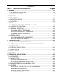
CONTENTS
PART I
INSTALLATION MANUAL
Pages
1. GENERAL ..............................................................................................................1-1
1.1 SAFE OPERATION NOTES .............................................................................1-1
1.2 PRODUCT CHANGES......................................................................................1-1
2. RECEIVING............................................................................................................2-1
3. INSTALLATION......................................................................................................3-1
3.1 MOUNTING SPACE..........................................................................................3-1
3.2 LOCATION........................................................................................................3-2
4. WIRING ..................................................................................................................4-1
4.1 NOTES ON WIRING TO PERIPHERAL UNITS ................................................4-1
4.2 CONNECTION DIAGRAM ................................................................................4-2
4.3 TERMINAL FUNCTION.....................................................................................4-3
4.3.1 MAIN CIRCUIT TERMINALS ..................................................................4-3
4.3.2 CONTROL CIRCUIT TERMINALS..........................................................4-3
4.3.3 MAIN CIRCUIT SCHEMATIC..................................................................4-4
4.4 WIRING PARTS ................................................................................................4-5
4.4.1 RECOMMENDED WIRING PARTS ........................................................4-5
4.4.2 CAUTIONS FOR WIRING ......................................................................4-7
5. TEST OPERATION ................................................................................................5-1
5.1 CHECK BEFORE TEST OPERATION ..............................................................5-1
5.2 SETTING THE LINE VOLTAGE SELECTING CONNECTOR ...........................5-1
6. MAINTENANCE .....................................................................................................6-1
6.1 PERIODIC INSPECTION..................................................................................6-1
6.2 SPARE PARTS .................................................................................................6-2
7. SPECIFICATIONS..................................................................................................7-1
8. DIMENSIONS.........................................................................................................8-1
9. PERIPHERAL AND OPTIONS...............................................................................9-1
9.1 AC REACTOR...................................................................................................9-1
9.2 NOISE FILTER..................................................................................................9-2
9.2.1 INPUT NOISE FILTER ............................................................................9-2
9.2.2 EMI SUPPRESSION ZERO CORE ........................................................9-3
9.3 BRAKING RESISTOR AND BRAKING UNIT ....................................................9-4
9.4 OTHERS ...........................................................................................................9-5
9.4.1 DIGITAL OPERATOR WITH EXTENSION WIRE ...................................9-5
9.4.2 ANALOG OPERATOR ............................................................................9-6
9.4.3 LED DIGITAL OPERATOR......................................................................9-6
9.4.4 OPTION CARDS.....................................................................................9-7
-
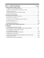
PART II
OPERATION MANUAL
Pages
1. DESCRIPTION OF USING 7200GS.......................................................................1-1
1.1 Using LCD (OR LED) digital operator ...............................................................1-1
1.2 DRIVE mode and PRGM mode displayed contents ..........................................1-3
1.3 Parameter description .......................................................................................1-4
1.4 Sample example of using LCD digital operator .................................................1-5
1.5 Control mode selection .....................................................................................1-7
2. SETTING USER CONSTANT ................................................................................2-1
2.1 Descriptions of Constant / function list ..............................................................2-1
2.2 Frequency Command An-□□ ..........................................................................2-2
2.3 Parameters Can Be Changed during Running Bn-□□ ....................................2-3
2.4 System Parameters Sn-□□.............................................................................2-10
2.5 Control Parameters Cn-□□ .............................................................................2-68
2.6 Monitoring Parameters Un-□□........................................................................2-88
3. FAULT DISPLAY AND TROUBLE SHOOTING .....................................................3-1
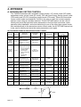
4. APPENDIX:
A. SENSORLESS VECTOR CONTROL .................................................................4-1
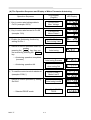
B. AUTO ENERGY-SAVING CONTROL IN PID CONTROL MODE........................4-4
C. PID CONTROL IN PID CONTROL MODE .........................................................4-9
D. PG FEEDBACK CONTROL ...............................................................................4-15
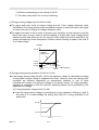
E. NOTES ON APPLICATION OF MOTORS ..........................................................4-19
F. PERIPHERAL UNIT NOTES ...............................................................................4-20
G. CIRCUIT PROTECTION AND ENVIRONMENTAL RATING NOTES .................4-21
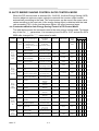
H. DRIVE INPUT FUSES........................................................................................4-23
I. CERTIFICATION FOR THE INVERTER ..............................................................4-24
-
PART I
INSTALLATION MANUAL
-
1. GENERAL
1.1 SAFE OPERATION NOTES
Read this installation manual thoroughly before installation, operation, maintenance
or inspection of the inverter. Only authorized personnel should be permitted to perform
maintenance, inspections or parts replacement.
In this manual, notes for safe operation are classified as:
"WARNING" or "CAUTION".
!
WARNING
: Indicates a potentially hazardous situation which, if not avoided,
could result in death or serious injury to personnel.
CAUTION
: Indicates a potentially hazardous situation which, if not avoided, may
result in minor or moderate injury to personnel and damage to
equipment. It may also be used to alert against unsafe practices.
This inverter has been placed through demanding tests at the factory before
shipment. After unpacking, check for the following:
1. Verify that part numbers on shipping carton and unit match the purchase order sheet
and/or packing list.
2. Do not install or operate any inverter which is damaged or missing parts.
3. Do not install or operate any inverter which has no QC marking.
Contact your local distributor or TECO representative if any of the above have been
found.
1.2 PRODUCT CHANGES
TECO reserves the right to discontinue or make modifications to the design of its
products without prior notice, and holds no obligation to make modifications to products
sold previously. TECO also holds no liability for losses of any kind which may result from
this action.
PARTⅠ
1-1
-
2. RECEIVING
!
CAUTION
This 7200GS has been put through demanding tests at the factory before shipment.
After unpacking, check the followings.
z Verify the received product with the purchase order sheet (invoice) and/or packing
list.
z Transit damage.
If any part of 7200GS is damaged or lost, immediately notify the shipper.
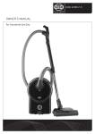
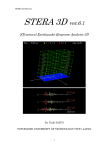
■ NAMEPLATE DATA ( 220V CLASS 75HP example )
MODEL
INPUT
OUTPUT
JNTEBGBA0075JK- - -
Inverter Model
220V CLASS INVERTER
AC 3PH 200-240V 50/60Hz
Input Spec.
Output Spec.
AC 3PH 0-240V 81KVA 212A
SER. NO.
Series No.
CE Mark
TECO Electric & Machinery Co., Ltd.
■ MODEL DESIGNATION
JNTEBGBA0075JK
--Reserved
Inverter Series
7200GS
Voltage
JK: 200~240V / 50, 60Hz
AZ: 380~480V / 50, 60Hz
Key pad
BG: LCD digital operator
BC: LED digital operator
Enclosures and
mountings
BA:Open chassis type(IEC IP00)
BB:Enclosed, wall-mounted type(NEMA-1)
PARTⅠ
2-1
Applicable maximum
motor output(HP)
0025:25HP
0400:400HP
-
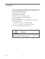
3. INSTALLATION
!
CAUTION
z Never move, lift or handle the 7200GS cabinet by the front cover.
z Lift the cabinet from the bottom.
z Do not drop the inverter.
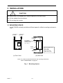
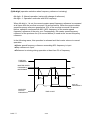
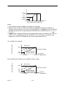
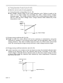
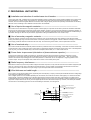
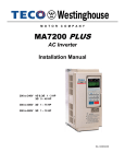
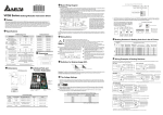
3.1 MOUNTING SPACE
Install 7200GS vertically and allow sufficient space for effective cooling as shown in
Fig. 1.
1.18in(30mm)
OR MORE
1.18in(30mm)
OR MORE
5.9in(150mm)
OR MORE
AIR
ALLOWABLE
TEMPERATURE OF
CONTROL PART:
131℉ (55℃)
FRONT
COVER
5.9in(150mm)
OR MORE
(a) Front View
AIR
OPEN CHASSIS TYPE:
113℉ (45℃)
ENCLOSED
WALL-MOUNTED
TYPE: 104℉ (40℃)
(b) Side View
Note: For product external dimensions and mounting dimensions,
refer to “DIMENSIONS” on page 23.
Fig. 1
PART Ⅰ
Mounting Spaces
3-1-
3.2 LOCATION
Location of the equipment is important to achieve proper performance
and normal operating life. The 7200GS should be installed in areas
where the following conditions exist:
z Protected from rain or moisture.
z Protected from direct sunlight.
z Protected from corrosive gases or liquids.
z Free from airborne dust or metallic particles.
z Free from vibration.
z Free from magnetic noise (e.g. welding machines, power units)
z Ambient temperature:
+14 to 104℉, -10 to +40℃ (For enclosed type),
+14 to 113℉, -10 to +45℃ (For open chassis type)
z Free from combustible materials, gases, etc.
!
CAUTION
When mounting multiple units in a common enclosure, install a
cooling fan or some other means to cool the air entering the
inverter to at least 113℉ (45℃) or below.
PART Ⅰ
3-2-
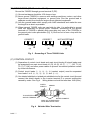
4. WIRING
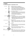
4.1 NOTES ON WIRING TO PERIPHERAL UNITS
Power Supply
MCCB
MC
AC REACTOR
z MCCB (molded case circuit breaker)
Please refer to Table 1. for MCCB selection.
Do not use a circuit breaker for start/stop operation.
When a ground fault interrupter is used, select the one
with no influence for high frequency. Setting current
should be 200mA or above and the operating time at
0.1 second or longer to prevent malfunction.
z MC (magnetic contactor)
It is not always necessary to have the MC on the input
side. However, an input MC can be used to prevent an
automatic restart after recovery from an external power
loss during remote control operation.
Do not use the MC for start/stop operation.
z AC REACTOR
To improve power factor or to reduce surge, install an
AC reactor. There is a DC choke built-in on 7200GS,
models 25HP(18.5 KW) and larger for 220V class and
30HP(22 KW) and larger for 440V class. The 440V 300
~ 400HP need to install AC reactor externally.
INPUT NOISE FILTER
z Input Noise Filter
When used with specified input noise filter, the
7200GS can comply with EN55011 class A. Please
refer to our EMC technical manual for noise filter
selection.
7200GS
z Inverter
Wire input to terminals L1, L2 and L3 for three phase
input. Make sure to connect the ground terminal to an
appropriate safety ground.
OUTPUT NOISE FILTER
3Φ AC
INDUCTION MOTOR
PART Ⅰ
z Output Noise Filter (EMI Suppression zero core)
When used with output noise filter, radiated and
conducted emissions may be reduced.
z Motor
When multiple motors are driven in parallel with an
inverter, the inverter rated current should be at least
1.1 times the total motor rated current. Make sure that
the motor and the inverters are separately grounded.
4-1-
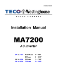
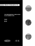
4.2 CONNECTION DIAGRAM
The following diagram shows interconnection of the main circuit and
control circuit. With the digital operator, the motor can be operated by
wiring the main circuit only. (Terminal Symbols: ◎ indicates main
circuit; ○ indicates control circuit).
BRAKING RESISTOR
UNIT (OPTION)
○
MCCB
POWER SUPPLYL1(R)
3-PHASE
200/208/220VAC,
L2(S)
50Hz
200/208/220/
230VAC, 60Hz
L2(S)
L3(T)
7200 GS
L3(T)
FORWARD
RUN/STOP
REVERSE
RUN/STOP
EXTERNAL
FAULT
1
2
FAULT RESET
STANDARD
FUNCTIONS
SET AT
FACTORY
PRIOR TO
SHIPMENT
B2
B1/P
L1(R)
MULTI-STEP SPEED SETTING 1
(MASTER/AUX)
3
EXTERNAL FAULT
4
RESET
6
7
EXTERNAL
COAST TO STOP
MOTOR
T2(V)
IM
T3(W)
PE
FORWARD RUN
AT CLOSED
REVERSE RUN
AT CLOSED
{GROUNDING
(100Ω OR LESS)}
FREQ. METER CALIBRATION
RESISTOR RV30YN20SB 20kΩ
21
ANALOG
MONITOR
5
MULTI-STEP
SPEED SETTING 2
JOG
COMMAND
T1(U)
MULTI-FUNCTION
INPUT
8
11
SEQUENCE
COMMON (0V)
(12)
FM
+
FREQ METER (METER SPECIFICATION: 3VDC 1mA)
18
19
12(G)
-
22
MULTI-FUNCTION ANALOG
OUTPUT *5
0 TO +10V
SIGNAL DURING RUNNING
IS SET AT FACTORY PRIOR
TO SHIPMENT
SHIELD
CONNECTION
20
FAULT CONTACT OUTPUT
CONTACT CAPACITY
250VAC 1A OR LESS
30VDC 1A OR LESS
2kΩ
EXTERNAL
FREQUENCY
COMMAND
2kΩ
0 TO +10V
3*
P
3*
4 TO 20mA
0 TO +10V
P
P
0V
15
13
SPEED SETTING POWER SUPPLY
+15V 20mA
MASTER SPEED REF.
0 TO 10V (20kΩ)
14
MASTER SPEED REF.
4 TO 20mA (250Ω)
16
17
MULTI-FUNCTION
ANALOG INPUT 0 TO 10V (20kΩ)
9
10
MULTI-FUNCTION
CONTACT OUTPUT
250VAC 1A OR LESS
30VDC 1A OR LESS
STANDARD OUTPUT AUX.
FREQUENCY REFERENCE
0V.
25
OPEN COLLECTOR 1
(ZERO SPEED SIGNAL IS
SET AT FACTORY)
26
OPEN COLLECTOR 2
(ZERO SPEED SIGNAL IS
SET AT FACTORY)
CAUTION
The connections of control circuit terminals
1 through 27 do not follow the terminal
numbering order. To connect them properly,
follow the figure below.
27
11 12 13 14 15 16 17 25 26 27
1 2 3 4 5 6 7 8 21 22
MULTI-FUNCTION OUTPUT
COMMON
9 10 18 19 20
Notes:
1.
indicates shielded wire and
P
twisted pair shielded wire.
2. Control circuit terminal 15 of +15V has maximum output current capacity of 20mA.
3. Either external terminal 13 or 14 can be used.
(For simultaneous input, two signals are internally added in the unit).
4. Multi-function analog output is an exclusive meter output such as frequency meter etc.
and not available for the feedback control system.
5. Control circuit terminal 12 is frame ground of the unit.
Fig. 2 Standard connection diagram.
PART Ⅰ
4-2-
MULTI-FUNCTION
OUTPUT
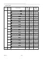
4.3 TERMINAL FUNCTION
4.3.1 MAIN CIRCUIT TERMINALS
Table 1.
HP Range
Terminals
R / L1
S / L2
T / L3
U / T1
V / T2
W / T3
B1/P
B2
-
○
220V: 25~100HP
440V: 30~400HP
440V: 25HP
Main Circuit Input Power Supply
Inverter Output
-
z B1/P - B2: Braking Resistor
- : DC power supply
z B1/P - ○
+
○
E ( PE,
Main Circuit Terminals
- : DC Power Supply or Braking Unit
+ ~○
z ○
-
)
Grounding (3rd Type Grounding)
4.3.2 CONTROL CIRCUIT TERMINALS
Table 2.
Terminal
1
2
3
4
5
6
7
8
9
10
11
12
13
14
15
16
17
18
19
20
21
22
25
26
27
PART Ⅰ
Control Circuit Terminals
Functions
Forward operation-stop signal
Reverse operation-stop signal
External fault input
Fault reset
Multi-function contact input: the following signals available to select. Forward/reverse select,
run mode select, multi-speed select, jog frequency select, accel/decel time select, external
fault, external coast to stop, hold command, inverter overheat prediction, DB command, aux.
input effective, speed search, energy-saving operation.
Multi-function contact output: one of the following signals available to output. Output during
running, zero speed, synchronized speed, arbitrary speed agreed, frequency detection,
overtorque, undervoltage, run mode, coast to stop, braking resistor overheat, alarm, fault.
Sequence control input common terminal.
Connection to shield sheath of signal lead.
Master speed voltage reference (0 to 10V).
Master speed current reference (4 to 20mA).
+15V
Aux. analog command: one of the following signals available to select. Frequency command,
frequency gain, frequency bias, overtorque detection level, voltage bias, accel/decel rate, DB
current.
Common terminal for control circuit (0V).
Fault contact output a (Closed at fault).
Fault contact output b (Open at fault).
Fault contact output common.
Multi-function analog monitor (+).
Output current or output
frequency is selectable.
Multi-function analog monitor (-).
Multi-function PHC output 1.
The same as terminals 9 and 10
Multi-function PHC output 2.
Multi-function PHC output common.
4-3-
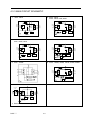
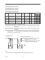
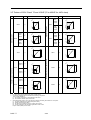
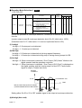
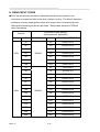
4.3.3 MAIN CIRCUIT SCHEMATIC
1. 440V : 25HP
2. 220V : 25HP
440V : 30HP, 40HP, 50HP
B1/P B2
+
○
DCL
R(L1)
R(L1)
U(T1)
+
S(L2)
T(L3)
U(T1)
+
S(L2)
V(T2)
V(T2)
T(L3)
W(T3)
W(T3)
○
○
RCC
E
CONTROL
CIRCUITS
RCC
X
CONTROL
CIRCUITS
E
X
3. 220V : 30HP, 40HP
440V : 60HP, 75HP
4. 220V : 50HP, 60HP, 75HP, 100HP
+
○
+
○
DCL
DCL
R(L1)
R(L1)
U(T1)
+
S(L2)
T(L3)
U(T1)
+
S(L2)
V(T2)
V(T2)
T(L3)
W(T3)
W(T3)
○
○
E
AC/
DC
CONTROL
CIRCUITS
RCC
CONTROL
CIRCUITS
RCC
X
E
5. 440V : 100HP
AC/
DC
X
6. 440V : 125HP, 150HP, 175HP, 215HP, 250HP
+
○
DCL
R(L1)
U(T1)
+
S(L2)
V(T2)
T(L3)
W(T3)
○
RCC
E
7. 440V : 300HP, 400HP
+
○
External
ACL
R(L1)
S(L2)
U(T1)
+
V(T2)
T(L3)
W(T3)
○
RCC
CONTROL
CIRCUITS
X
E
* External ACL is necessary
PART Ⅰ
4-4-
AC/
DC
X
CONTROL
CIRCUITS
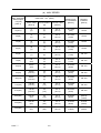
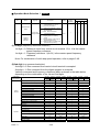
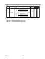
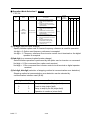
4.4 WIRING PARTS
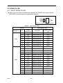
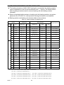
4.4.1 RECOMMENDED WIRING PARTS
Be sure to connect MCCBs between power supply and 7200GS input terminals
L1 (R), L2 (S), L3 (T). Recommended MCCBs are listed in Table 3.
When a ground fault interrupter is used, select the one with no influence for high
frequency. The current setting should be 200mA or over and operating time, 0.1 second
or over to prevent malfunction.
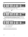
Table 3.
220V and 440V class applicable wire size and contactor
(a) 220V SERIES
Max. Applicable
Motor Output
HP (KW)
[Note 1]
Cable Size - mm2 (AWG)
Molded-Case
Circuit Breaker
[Note 4]
Magnetic
Contactor
[Note 4]
Power Cable
[Note 2]
Ground Cable E
[G]
Control Cable
[Note 3]
25(18.5)
22
(4)
14
(6)
0.5~2
(20-14)
TO-225S
(150A)
CN-80
30(22)
30
(2)
14
(6)
0.5~2
(20-14)
TO-225S
(175A)
CN-100
40(30)
60
(2/0)
22
(4)
0.5~2
(20-14)
TO-225S
(175A)
CN-125
50(37)
60×2P
(2/0)
22
(4)
0.5~2
(20-14)
TO-225S
(200A)
CN-150
60(45)
60×2P
(2/0×2P)
22
(4)
0.5~2
(20-14)
TO-225S
(225A)
CN-180
75(55)
60×2P
(2/0×2P)
30
(2)
0.5~2
(20-14)
TO-400S
(300A)
CN-300
100(75)
100×2P
(4/0×2P)
50
(1/0)
0.5~2
(20-14)
TO-400S
(400A)
CN-300
[Note] 1. For Constant Torque Load.
+ , ○
- , BR, U (T1),
2. Power Cable Include Cables to the Terminals R (L1), S (L2), T (L3), ○
V (T2), W (T3).
3. Control Cable Include Cables to the Control Terminals.
4. The Molded-Case Circuit Breaker and Magnetic Contactors Shown in Table are TECO
Products and are for reference only. Other manufactures' equivalent products may be
selected.
5. The Magnetic contactors S-K400 and S-K600 are Mitsubishi Products and are for reference
only. Other manufactures' equivalent products may be selected.
PART Ⅰ
4-5-
(b) 440V SERIES
Max. Applicable
Motor Output
HP (KW)
[Note 1]
Cable Size - mm2 (AWG)
Molded-Case
Circuit Breaker
[Note 4]
Magnetic
Contactor
[Note 4]
Power Cable
[Note 2]
Ground Cable E
[G]
Control Cable
[Note 3]
25(18.5)
8
(8)
8
(8)
0.5~2
(20-14)
TO-100S
(75A)
CN-50
30(22)
14
(6)
8
(8)
0.5~2
(20-14)
TO-100S
(100A)
CN-50
40(30)
22
(4)
8
(8)
0.5~2
(20-14)
TO-100S
(100A)
CN-65
50(37)
22
(4)
14
(6)
0.5~2
(20-14)
TO-125S
(125A)
CN-80
60(45)
38
(1)
14
(6)
0.5~2
(20-14)
TO-225S
(175A)
CN-100
75(55)
60
(2/0)
22
(4)
0.5~2
(20-14)
TO-225S
(175A)
CN-125
100(75)
60×2P
(2/0)
22
(4)
0.5~2
(20-14)
TO-225S
(225A)
CN-150
125(90)
60×2P
(2/0×2P)
30
(2)
0.5~2
(20-14)
TO-400S
(300A)
CN-300
150(110)
60×2P
(2/0×2P)
30
(2)
0.5~2
(20-14)
TO-400S
(300A)
CN-300
175(132)
100×2P
(4/0×2P)
50
(1/0)
0.5~2
(20-14)
TO-400S
(400A)
CN-300
215(160)
100×2P
(4/0×2P)
50
(1/0)
0.5~2
(20-14)
TO-400S
(400A)
CN-300
250(185)
250×2P
(2P)
50
(1/0)
0.5~2
(20-14)
TO-600S
(600A)
S-K400
[Note 5]
(450A)
300(220)
250×2P
(2P)
60
(2/0)
0.5~2
(20-14)
TO-800S
(800A)
S-K600
(800A)
400(300)
250×2P
(2P)
60
(2/0)
0.5~2
(20-14)
TE-1000
(1000A)
S-K600
(800A)
PART Ⅰ
4-6-
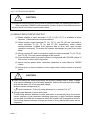
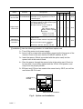
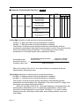
4.4.2 CAUTIONS FOR WIRING
!
CAUTION
The external interconnection wiring must be performed with the following procedures.
After completing 7200GS interconnections, be sure to check that connections are
correct. Never use control circuit buzzer check.
(A) MAIN CIRCUIT INPUT/OUTPUT
(1) Phase rotation of input terminals L1 (R), L2 (S), L3 (T) is available in either
direction. (Clockwise and counterclockwise).
(2) When inverter output terminals T1 (U), T2 (V), and T3 (W) are connected to
motor terminals T1 (U), T2 (V), and T3 (W), respectively, motor rotates
counterclockwise. (Viewed from opposite side of drive end, upon forward
operation command). To reverse the rotation interchange any two of the motor
leads.
(3) Never connect AC main circuit power supply to output terminals T1 (U), T2 (V),
and T3 (W). This may cause damage to the inverter.
(4) Care should be taken to prevent contact of wiring leads with 7200GS cabinet. If
this occurs, a short-circuit may result.
(5) Never connect power factor correction capacitors or noise filters to 7200GS
output.
(6) Never open or close contactors in the output circuit unless inverter is properly
sized.
!
CAUTION
z Lead size should be determined taking into account voltage drop of leads. Voltage
drop can be obtained by the following equation: select such lead size that voltage
drop will be within 2% of normal rated voltage.
phase-to-phase voltage drop (V)
= 3 x lead resistance ( Ω /km) X wiring distance(m) x current(A) X 10-3 .
z Wiring length between inverter and motor.
If total wiring distance between inverter and motor is excessively long and inverter
carrier frequency (main transistor switching frequency) is high, harmonic leakage
current from the cable will increase to effect the inverter unit or peripheral devices.
If the wiring distance between inverter and motor is long, reduce the inverter carrier
frequency.
PART Ⅰ
4-7-
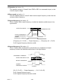
(B) GROUNDING (PE: Protective Earth)
Ground the 7200GS through ground terminal E (PE).
(1) Ground resistance should be 100 ohms or less.
(2) Never ground 7200GS in common with welding machines, motors, and other
large-current electrical equipment, or ground pole. Run the ground lead in
separate conduit from leads for large-current electrical equipment.
(3) Use the ground leads which comply with AWG standards and make the sure
the length is as short as possible.
(4) Where several 7200GS units are used side by side, it is preferable to ground
each unit separately to ground poles. However, connecting all the ground
terminals of 7200GS in parallel while grounding only one of the 7200GS’s to
the ground pole is also permissible (Fig. 3). Be sure not to form a loop with the
ground leads.
CORRECT
CORRECT
PE
PE
PE
PE
PE
(a)
PE
NOT ACCEPTABLE
PE
(b)
PE
PE
(c)
Fig. 3 Grounding of Three 7200GS Units
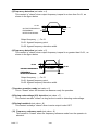
(C) CONTROL CIRCUIT
(1) Separation of control circuit leads and main circuit leads: All signal leads must
+ , ○
- , B2, T1 (U),
be separated from main circuit leads L1 (R), L2 (S), L3 (T), ○
T2 (V), T3 (W) and other power cables to prevent erroneous operation caused
by noise interference.
9 , ○
10 , ○
18 , ○
19 , ○
20 (contact output) must be separated
(2) Control circuit leads ○
21
22
25
26
27
11 ∼○
17 .
from leads 1 to 8, ○, ○, ○, ○, ○ and ○
(3) Use twisted shielded or twisted pair shielded wire for the control circuit line and
connect the shield sheath to the inverter terminal E to prevent malfunction
caused by noise. See Fig.4. Wiring distance should be less than 164ft (50m).
SHIELD
SHEATH
TO INVERTER SHIELD
SHEATH TERMINAL E
ARMOR
NEVER CONNECT
INSULATE THESE PARTS
WITH INSULATING TAPE.
Fig. 4 Shielded Wire Termination
PART Ⅰ
4-8-
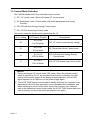
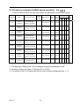
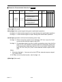
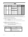
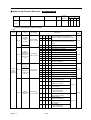
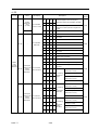
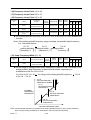
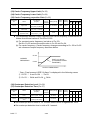
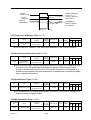
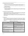
4.4.3 Fuse types
Drive input fuses are provided to disconnect the drive from power in the event that a component fails in the
drive’s power circuitry. The drive’s electronic protection circuitry is designed to clear drive output short circuits
and ground faults without blowing the drive input fuses. Below table shows the 7200GS input fuse ratings.
To protect the inverter most effectively, use fuses with current-limit function.
220V class
MODEL
HP
KVA
JNTEBG□□7R50JK
7.5
JNTEBG□□0010JK
Rated Input AMPS
FUSE Rating
10.3
100% CONT. Output
AMPS
24
29
50
10
13.7
32
38
60
JNTEBG□□0015JK
15
20.6
48
58
100
JNTEBG□□0020JK
20
27.4
64
77
125
JNTEBG□□0025JK
25
34
80
88
125
JNTEBG□□0030JK
30
41
96
106
150
JNTEBG□□0040JK
40
54
130
143
200
JNTEBG□□0050JK
50
57
160
176
250
JNTEBG□□0060JK
60
67
183
201
300
JNTEBG□□0075JK
75
85
224
246
350
JNTEBG□□0100JK
100
128
300
330
450
MODEL
HP
KVA
Rated Input AMPS
FUSE Rating
JNTEBG□□7R50AZ
7.5
10.3
100% CONT. Output
AMPS
12
14
25
JNTEBG□□0010AZ
10
13.7
16
19
30
JNTEBG□□0015AZ
15
20.6
24
29
50
JNTEBG□□0020AZ
20
27.4
32
38
60
JNTEBG□□0025AZ
25
34
40
48
70
JNTEBG□□0030AZ
30
41
48
53
80
JNTEBG□□0040AZ
40
54
64
70
100
JNTEBG□□0050AZ
50
68
80
88
125
JNTEBG□□0060AZ
60
82
96
106
150
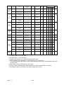
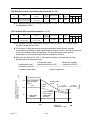
440V class
JNTEBG□□0075AZ
75
110
128
141
200
JNTEBG□□0100AZ
100
138
165
182
250
JNTEBG□□0125AZ
125
180
192
211
300
JNTEBG□□0150AZ
150
195
224
246
350
JNTEBG□□0175AZ
175
230
270
297
400
JNTEBG□□0215AZ
215
260
300
330
450
JNTEBG□□0250AZ
250
290
340
374
500
JNTEBG□□0300AZ
300
385
450
540
700
JNTEBG□□0400AZ
400
513
600
720
900
Fuse Type
UL designated SEMICONDUCTOR PROTECTION FUSES
Class
CC, J, T, RK1 or RK5
Voltage Range: 300V for drives with 230V class VFD
500V for drives with 460V class VFD
PART Ⅰ
4-9-
5. TEST OPERATION
To assure safety, prior to test operation, disconnect the coupling or belt
which connects the motor with the machine so that motor operation is
isolated. If an operation must be performed while the motor is directly
connected to the machine, use great care to avoid any possible
hazardous condition.
5.1 CHECK BEFORE TEST OPERATION
After completion of installation and wiring, check for
(1) proper wiring
(2) short-circuit due to wire clippings
(3) loose screw-type terminals
(4) proper load
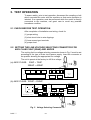
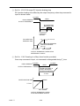
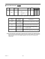
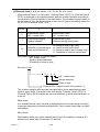
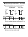
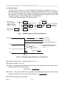
5.2 SETTING THE LINE VOLTAGE SELECTING CONNECTOR FOR
460V CLASS 30HP (22kW) AND ABOVE
The cooling fan line voltage selecting connector shown in Fig. 5 must be set
according to the type of main circuit power supply. Insert the connector at
the position showing the appropriate line voltage.
The unit is preset at the factory to 440 line voltage.
(a) 440V CLASS:
30HP ~ 75HP
300HP ~ 400HP
1 23CN 3
1 24CN 3
1 25CN 3
1 26CN 3
JP1
JP2
380V 400/415
1 21CN 4
FU2
JP3
JP4
440V
460V
1 22CN 4
R
1
TB2
S
(220) 2
R
1
(440) S
TB3
2
(b) 440V CLASS: 100HP ~ 250HP
33CN
TB4(220V)
SA4(220V)
FU1
2
26CN
1
TB3
440V
34CN
220V
35CN
32CN
25CN
36CN
VER.03
400/415
440V
460V
1 JP4
4P108C0010103
380V
1 JP3
DM1
440V
31CN
1 JP2
+
1 JP1
220V
Fig. 5 Voltage Selecting Connector
PART Ⅰ
5-1-
TB2
S
R
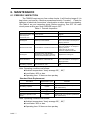
6. MAINTENANCE
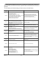
6.1 PERIODIC INSPECTION
The 7200GS requires very few routine checks. It will function longer if it is
kept clean, cool and dry. Observe precautions listed in "Location". Check for
tightness of electrical connections, discoloration or other signs of overheating.
Use Table 4 as your inspection guide. Before servicing, turn OFF AC main
circuit power and be sure that CHARGE lamp is OFF.
Table 4 Periodic Inspection
Component
Check
Corrective Action
External terminals, unit Loose screws
mounting bolts,
Loose connectors
connectors, etc.
Tighten
Tighten
Blow with dry compressed air of
39.2 ×10⁴ to 58.8 x 10⁴ Pa (57 to
85psi.) pressure.
Cooling fins
Build-up of dust and dirt
Printed circuit board
Blow with dry compressed air of
4
4
39.2 x10 to 58.8 x 10 Pa (57 to
Accumulation of conductive dust or oil 85psi.) pressure.
If dust and oil cannot be
removed, replace the board.
Cooling fan
Abnormal noise and vibration.
Whether the cumulative operation
time exceeds 20,000 hours or not.
Replace the cooling fan.
Power elements
Accumulation of dust and dirt
Blow with dry compressed air of
39.2 x10⁴ to 58.8 x 10⁴ Pa (57 to
85psi) pressure.
Smoothing capacitor
Discoloration or odor
Replace the capacitor or inverter
unit.
Note: Operating conditions as follows:
z Ambient temperature: Yearly average 30℃, 86℉
z Load factor: 80% or less
z Operating time: 12 hours or less per day
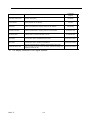
Standard Parts Replacement
Item Name
Cooling fan
Smoothing capacitor
Replacement Cycle
2 or 3 years
5 years
Remarks
Replace with a new product.
Replace with a new product. (Determine
after examination).
-
Determine after examination.
Fuse
10 years
Replace with a new product.
Aluminum capacitor on PC
board
5 years
Replace with a new product. (Determine
after examination).
Circuit Breakers and relays
Note: Operating conditions as follows:
z Ambient temperature: Yearly average 30℃, 86℉
z Load factor: 80% or less
z Operating time: 20 hours or less per day
PART Ⅰ
6-1-
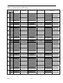
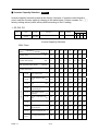
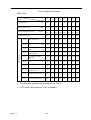
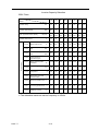
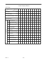
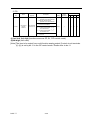
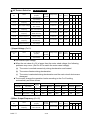
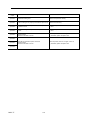
6.2 SPARE PARTS
As insurance against costly downtime, it is strongly recommended that
renewal parts be kept on hand in accordance with the table below. When
ordering renewal parts, please specify to your local distributor or TECO
representative the following information: Part Name, Part Code No. and
Quantity.
Table 5
Spare Parts for 220V Class
INVERTER & PARTS NAME
HP
25
30
40
50
60
75
100
PART Ⅰ
Control PC Board*
Power Board
Main Circuit
Transistor
Main Circuit Diode
Cooling Fan
MODEL
-
-
CM200DU-12H
DF200BA080
4E-230B
CODE
4H300D4820002
3P106C0670008
277810212
277192187
3M903D0450004
Qty
1
1
3
1
2
MODEL
-
-
CM200DU-12F
DF200BA080
4E-230B
CODE
4H300D4820002
4P106C02900B1
277810255
277192187
3M903D0450004
Qty
1
1
3
1
2
MODEL
-
-
CM300HA-12H
2R160E-080
4E-230B
CODE
4H300D4820002
3P106C06400D4
3H324D0460000
277051532
3M903D0450004
Qty
1
1
6
6
3
MODEL
-
-
CM400HA-12H
2RI60E-080
4E-230B
CODE
4H300D4820002
3P106C06400E2
277800179
277051532
3M903D0450004
Qty
1
1
6
6
3
MODEL
-
-
1MBI600NP-060
2RI60E-080
4E-230B
CODE
4H300D4820002
3P106C06400F1
277800195
277051532
3M903D0450004
Qty
1
1
6
6
3
MODEL
-
-
1MBI600NP-060
2RI60E-080
4E-230B
CODE
4H300D4820002
3P106C06400G9
277800195
277051532
3M903D0450004
Qty
1
1
6
6
3
MODEL
-
-
CM300HA-12H
2RI100E-080
S175-2-HWB
CODE
4H300D4820002
3P106C06400H7
3H324D0460000
277051516
279152115
Qty
1
1
12
6
3
SPEC
6-2-
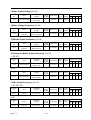
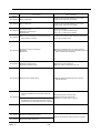
Table 6
Spare Parts for 440V Class
INVERTER &
PART NAME
HP
30
40
50
60
75
100
125
150
175
215
250
300
400
Power Board
Main Circuit Transistor
Main Circuit Diode
-
-
7MBP075RA120
DF75LA160
AFB0824SH-B
-
277831538
277192195
4H300D1050001
-
2
-
Cooling Fan
SPEC
MODEL
25
Control PC
Board*
CODE 4H300D4820002 3P106C06500C1
Qty
1
1
1
1
MODEL
-
-
CM100DU-24F
DF75LA160
A2123-HBT
ASB0624H-B
277810280
277192195
4M903D1890001
4H300D1060007
2
1
CODE 4H300D4820002 4P106C02900A2
Qty
1
1
3
1
MODEL
-
-
CM150DU-24F
DF100LA160
A2123-HBT
ASB0624H-B
277810298
277192217
4M903D1890001
4H300D1060007
2
1
CODE 4H300D4820002 4P106C02900A2
Qty
1
1
3
1
MODEL
-
-
CM200DU-24F
2U/DDB6U145N16L
A2123-HBT
ASB0624H-B
277810301
277190222
4M903D1890001
4H300D1060007
2
1
CODE 4H300D4820002 4P106C02900A2
Qty
1
1
3
1
MODEL
-
-
CM200DU-24F
2U/DDB6U145N16L
AFB1224SHE
AFB0824SH-B
277810301
277190222
4M903D1880006
4H300D1440004
2
1
CODE 4H300D4820002 4P106C02900A2
Qty
1
1
3
1
MODEL
-
-
CM300DU-24F
2U/DDB6U205N16L
AFB1224SHE
AFB0824SH-B
277810310
277190249
4M903D1880006
4H300D1440004
2
1
CODE 4H300D4820002 4P106C02900A2
Qty
1
1
3
1
MODEL
-
-
SKM400GB128D
SKKH106/16E
FFB1224EHE
ASB0624H-B
277810611
277112302
4H300D5110009
4H300D1060007
2
1
CODE 4H300D4820002 4P106C02900D7
Qty
1
1
3
3
MODEL
-
-
CM600HU-24F
2RI100G-160
AFB1224SHE
A2123-HBT
277800225
277051524
4M903D1880006
4M903D1890001
3
1
CODE 4H300D4820002 4P106C02700A1
Qty
1
1
6
6
MODEL
-
-
CM600HU-24F
2RI100G-160
AFB1224SHE
A2123-HBT
277800225
277051524
4M903D1880006
4M903D1890001
3
1
CODE 4H300D4820002 4P106C02700A1
Qty
1
1
6
6
MODEL
-
-
CM600HU-24F
2RI100G-160
AFB1224SHE
A2123-HBT
277800225
277051524
4M903D1880006
4M903D1890001
3
1
CODE 4H300D4820002 4P106C02700A1
Qty
1
1
6
6
MODEL
-
-
CM400HU-24F
2RI100G-160
EFB1524HHG
A2123-HBT
277800217
277051524
4M300D3680002
4M903D1890001
3
1
CODE 4H300D4820002 4P106C02700A1
Qty
1
1
12
6
MODEL
-
-
CM400HU-24F
2RI100G-160
EFB1524HHG
A2123-HBT
277800217
277051524
4M300D3680002
4M903D1890001
6
3
1
CODE 4H300D4820002 4P106C02700A1
Qty
1
1
12
MODEL
-
-
Skiip1203GB122-2DL
SKKH500/E16
2RRE45250﹡56R
-
4M903D2030006
4M903D2000000
4M903D1940009
-
3
2
-
CODE 4H300D4820002 3P106C0060009
Qty
1
1
3
MODEL
-
-
Skiip1513GB122-2DL
SKKH500/E16
2RRE45250﹡56R
-
4M903D2040001
4M903D2000000
4M903D1940009
-
3
3
2
-
CODE 4H300D4820002 3P106C0060009
Qty
PART Ⅰ
1
1
6-3-
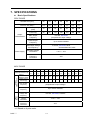
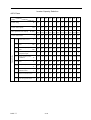
7. SPECIFICATIONS
z
Basic Specifications
220V CLASS
INVERTER (HP)
25
MAX. APPLICABLE MOTOR
OUTPUT HP (KW)*1
Inverter Capacity
(KVA)
Rated Output
Current (A)
Output
Max. Output
Characteristics
Frequency
30
50
60
75
100
25
30
40
50
60
75
100
(18.5)
(22)
(30)
(37
(45)
(55)
(75)
34
41
54
57
67
85
128
80
96
130
160
183
224
300
3-Phase, 200~240V
(Proportional to input voltage)
Rated Output
Frequency
Up to 400Hz available
3-Phase, 200~240V, 50Hz
200/208/220/230V, 60Hz
Rated Input Voltage
And Frequency
Power Supply
40
Allowable Voltage
Fluctuation
+10% ~ -15%
Allowable
Frequency
Fluctuation
±5%
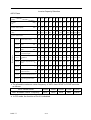
440V CLASS
Power
Supply
Output
Characteristics
INVERTER (HP)
MAX. APPLICABLE
MOTOR OUTPUT HP
(KW)*1
Inverter
Capacity (KVA)
Rated Output
Current (A)
25
30
40
50
60
75
100
125
175
215
250
300
400
25
30
40
50
60
75
100
125
150
175
215
250
300
400
(18.5)
(22)
(30)
(37)
(45)
(55)
(75)
(90)
(110)
(132)
(160)
(185)
(220)
(300)
34
41
54
68
82
110
138
180
195
230
260
290
385
513
40
48
64
80
96
128
165
192
224
270
300
340
450
600
Max. Output
Frequency
3-Phase, 380~480V
(Proportional to input voltage)
Rated Output
Frequency
Up to 400Hz available
Rated Input
Voltage And
Frequency
3-Phase, 380~480V, 50/60Hz
Allowable
Voltage
Fluctuation
+10% ~ -15%
Allowable
Frequency
Fluctuation
±5%
*1 Based on 4 pole motor
PART Ⅰ
150
7-1-
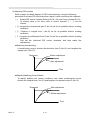
CHARACTERISTICS
Control Method
z Sine wave PWM
z Four control modes (switched by parameter)
- V/F control
- Sensorless vector control (With Auto-tuning)
- PID&Auto Energy Saving control
Environmental
Conditions
Protective Functions
Control Characteristics
- V/F+PG control
Starting Torque
z V/F control: 150% at 3Hz
z Sensorless Vector control: 150% at 1Hz
Speed Control Range
z V/F control: 1 : 10
z Sensorless Vector control:
Speed Response
1 : 60
5Hz (Sensorless Vector)
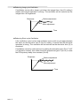
Speed Control Accuracy
z V/F control: ±1% (with slip compensation)
z V/F+PG Control : ±0.03%
Frequency Control Range
0.1 ~ 400.0Hz
Frequency Setting Resolution
Digital reference: 0.01Hz (100Hz Below); Analog reference: 0.06Hz/60Hz
Frequency Accuracy
Digital reference: ±0.01% (-10 ~ +40℃); Analog command: ±0.1% (25℃± 10℃)
Output Frequency Resolution
0.01Hz (1/30000)
Frequency Setting Signal
0 ~ 10VDC (20KΩ), 4~20mA (250Ω)
z Sensorless Vector control: ±0.5%
Overload Capacity
150% rated output current for 1 minute.
Accel/Decel Time
0.1 ~ 6000.0 sec (Accel/Decel time settings independently)
Efficiency at Rated Freq.
0.95 above
Braking Torque
Approx. 20% (Approx. 125% When using braking resistor)
Inverter of 220V 20HP (15KW) or less and 440V 25HP (18.5KW) or less have a
Built-in braking transistor
Motor Overload Protection
Electric thermal overload relay
Instantaneous Overcurrent (OC)
and Short Circuit Protection
Motor coasts to stop at approx. 200% rated output current.
Inverter Overheat Protection
(OL2)
150% inverter rated output current for 1 min.
Overvoltage (OV)
Motor coasts to stop if the main circuit voltage exceeds 410VDC (820VDC for
440V class)
Undervoltage (UV)
Motor coasts to stop if the main circuit voltage drops to 190VDC (380VDC for
440V class)
Momentary Power Loss
Immediately stop after 15 ms or longer power loss (at factory setting)
Continuous operation during power loss less than 2 sec. (standard)
Fin Overheat (OH)
Thermostat
Stall Prevention
Stall prevention during acceleration/deceleration and constant speed operation.
Ground Fault (GF)
Provided by electronic circuit.
Power Charge Indication
Indicates until main circuit voltage reaches 50V.
Location
Indoor (Protected from corrosive gases and dust)
Humidity
95% RH (non-condensing)
Storage Temperature
-20 ~+60℃ (for short period during shipping)
Ambient Temperature
-10 to +40℃ (for NEMA1 type); -10 to +45℃ (for open chassis type)
Altitude
1000m or below
Vibration
9.8m/s at 20Hz or below, up to 2m/s at 20 to 50Hz
2
2
Communication Function
MODBUS, PROFIBUS (option)
EMI
Meet EN 50081-2 (1994) with specified EMI filter
EMC Compatibility
Meet Pr EN50082-2
PART Ⅰ
7-2-
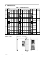
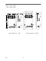
8. DIMENSIONS
Table 7 Dimension and Weight
Inverter Open Chassis Type (IP00) mm
Voltage
Weight
Capacity
(V)
(Kg)
W
H
D W1 H1 d
(HP)
Enclosed Type (NEMA1) mm
W
H
D
291.5
745
307
W1 H1
d
Weight
(Kg)
ACL/DCL
Reference
Figure
DCL Built-in
(Standard)
(b)
External ACL
(option)
(a)
25
283.5 525
307 220 505 M8
30
220 505 M8
33
30
40
220V
75
50
76
459
790 324.6 320 760 M10
82
462
1105
324.6 320 760 M10
60
79
85
75
79
88
100
599 1000 381.6 460 960 M12
120
602
1305
25
265
12
265
360
225
245 340 M6
291.5
745
307
220 505 M8
360
225 245 340 M6
283.5 525
307 220 505 M8
30
381.6 460 960 M12
36
130
12
38
40
36
38
50
47
50
60
47
344
440V
81
630 324.5 250 610 M8
50
352
945
324.5 250 610 M8
75
47
50
100
62
65
125
150
80
459
790 324.6 320 760 M10
175
81
85
462
1105
324.6 320 760 M10
81
215
250
1305
381.6 460 960 M12
400
176
730
1330
382
690 930 M12
190
196
W
W1
d
H
1
H
(a) 440V:25HP
H2
PART Ⅰ
DCL Built-in
(Standard)
139
170
730 1230 382 690 930 M12
(b)
DCL Built-in
(Standard)
86
139
602
132
300
DCL Built-in
(Standard)
86
132
599 1000 381.6 460 960 M12
DCL Built-in
(Standard)
8-1-
External ACL
(option)
D
(c)
(b) 220V:25HP∼100HP
440V:30HP∼250HP
W
W1
D
H
H
H1
H1
W
W1
D
d
d
(Open Chassis Type -IP00)
PART Ⅰ
(Wall-mounted Type-NEMA1)
8-2-
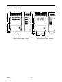
(d) 440V:300HP, 400HP
W
D
W
W1
D
W1
d
365
365
H
H
365
365
d
DRIVE
FW D
REV
REM O TE
SEQ REF
DRIVE
PRGM
FW D
REV
REM O TE
SEQ REF
DSPL
DRIVE
DATA
JO G
PRGM
EN TER
DSPL
DRIVE
FW D
DATA
JO G
REV
EN TER
RESET
RU N
FW D
STO P
REV
RESET
STO P
23
500
122
200
200
RU N
500
(Open Chassis Type -IP00)
PART Ⅰ
(Wall-mounted Type-NEMA1)
8-3-
9. PERIPHERAL AND OPTIONS
9.1 AC REACTOR
z When power capacity is significantly large compared to inverter capacity, or when
the power factor needs to be improved, externally connect an AC reactor.
z 7200GS 220V 25 ~ 100HP and 440V 30 ~ 250HP have built-in DC reactor as
standard. (When the power factor needs to be improved, externally connect an AC
reactor).
z 440V 25HP connects an optional AC reactor When the power factor needs to be
improved.
z 440V 300 ~ 400HP need to connect an AC reactor externally.
Table 8 AC REACTOR
Inverter
Voltage
220V
440V
PART Ⅰ
HP
AC Reactor
Rated current (A) Current (A) Inductance (mH)
25
80
90
0.12
30
96
120
0.09
40
130
160
0.07
50
160
200
0.05
60
183
240
0.044
75
224
280
0.038
100
300
360
0.026
25
40
50
0.42
30
48
60
0.36
40
64
80
0.26
50
80
90
0.24
60
96
120
0.18
75
128
150
0.15
100
169
200
0.11
125
192
200
0.11
150
224
250
0.09
175
270
330
0.06
215
300
330
0.06
250
340
400
0.05
300
450
500
0.04
400
600
670
0.032
9-1-
9.2 NOISE FILTER
9.2.1 INPUT NOISE FILTER
z When input noise filter is installed as indicated, the 7200GS will comply with the
EN61800-3 noise interference suppression directive.
Input Noise Filter
MCCB
1
4
PA
R/L1 U/T1
S
2
5
S/L2
T
3
6
T/L3 W/T3
R
IN
V/T2
I
Input Noise Filter Connection Example
Table 9 Input Noise Filter
Inverter
Voltage (V)
220V
440V
PART Ⅰ
Input Noise Filter
Rated current
Model NO.
(A)
FS6100-90-34
90A
25
Rated
current (A)
80A
30
96A
FS6100-150-40
150A
40
130A
FS6100-150-40
150A
50
160A
FS6100-250-99
250A
60
183A
FS6100-250-99
250A
75
224A
FS6100-400-99
400A
100
300A
FS6100-400-99
400A
25
40A
FS6101-50-52
50A
30
48A
FS6101-80-52
80A
40
64A
FS6101-80-52
80A
50
80A
FS6101-120-35
120A
60
96A
FS6101-120-35
120A
75
128A
FS6101-200-40
200A
100
165A
FS6101-200-40
200A
125
192A
FS6101-320-99
320A
150
224A
FS6101-320-99
320A
175
270A
FS6101-320-99
320A
215
300A
FS6101-400-99-1
400A
250
340A
FS6101-400-99-1
400A
300
450A
FS6101-600-99
600A
400
600A
FS6101-800-99
800A
HP
9-2-
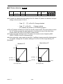
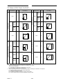
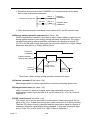
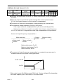
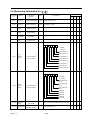
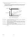
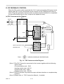
9.2.2 EMI SUPPRESSION ZERO CORE
z Model: JUNFOC046S - - - - - - z Code No.: 4H000D0250001
z According to the required power rating and wire size, select the matched ferrite core
to suppress the zero sequence EMI filter.
z The ferrite core can attenuate the frequency response at high frequency range (from
100KHz to 50MHz, as shown below). It should be able to attenuate the RFI from
inverter to outside.
z The zero-sequence noise filter ferrite core can be installed either on the input side or
on the output side. The wire around the core for each phase should be winded by
following the same convention and one direction. The more winding turns the better
attenuation effect. (Without saturation). If the wire size is too big to be winded, all the
wire can be grouped and go through these several cores together in one direction.
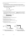
z Frequency attenuation characteristics (10 windings case)
attenuation value (dB)
0
-10
-20
-30
-40
101
102
103
104
Interference Frequency (kHz)
Example: EMI suppression zero core application example
DRIVE FWD REV
REMOTE
DIGITAL OPERATOR JNEP-31
PRGM
DRIVE
JOG
FWD
REV
RUN
DSPL
EDIT
ENTER
RESET
STOP
Note: All the line wire of U/T1, V/T2, W/T3 phase must pass through the same
zero-phase core in the same winding sense.
PART Ⅰ
9-3-
105
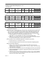
9.3 BRAKING RESISTOR AND BRAKING UNIT
z The braking transistor of 440V 25HP was built-in as standard, the braking resistor
+ directly. The others without
can be connected to main circuit terminals B2 and ○
built-in braking transistor need to connect braking unit with braking resistor
externally.
z When connecting braking resistor or braking unit with braking resistor, set system
parameter Sn-10=XX1X (i.e. stall prevention during deceleration not enabled).
z Braking resistor and braking unit selection table is shown below.
Table 10 Braking Resistor and Braking Unit
Inverter
Braking Resistor
Braking Torque (%)
Rated current
(A)
MODEL NO.
Number
used
MODEL NO.
Specs.
Number
used
25
80A
JNTBU-230
1
JNBR-4R8KW8
4800W/8Ω
1
119%(10%ED)
30
96A
JNTBU-230
1
JNBR-4R8KW6R8
4800W/6.8Ω
1
117%(10%ED)
40
130A
JNTBU-230
2
JNBR-3KW10
3000W/10Ω
2
119%(10%ED)
50
160A
JNTBU-230
2
JNBR-3KW10
3000W/10Ω
2
99%(10%ED)
60
183A
JNTBU-230
2
JNBR-4R8KW6R8
4800W/6.8Ω
2
117%(10%ED)
75
224A
JNTBU-230
3
JNBR-4R8KW6R8
4800W/6.8Ω
2
98%(10%ED)
100
300A
JNTBU-230
3
JNBR-4R8KW6R8
4800W/6.8Ω
3
108%(10%ED)
25
40A
-
-
JNBR-1R6KW50
1600W/50Ω
1
84%(10%ED)
30
48A
JNTBU-430
1
JNBR-4R8KW27R2
4800W/27.2Ω
1
117%(10%ED)
40
64A
JNTBU-430
1
JNBR-6KW20
6000W/20Ω
1
119%(10%ED)
50
80A
JNTBU-430
2
JNBR-4R8KW32
4800W/32Ω
2
119%(10%ED)
60
96A
JNTBU-430
2
JNBR-4R8KW27R2
4800W/27.2Ω
2
117%(10%ED)
75
128A
JNTBU-430
2
JNBR-6KW20
6000W/20Ω
2
126%(10%ED)
100
165A
JNTBU-430
3
JNBR-6KW20
6000W/20Ω
3
139%(10%ED)
125
192A
JNTBU-430
3
JNBR-6KW20
6000W/20Ω
3
115%(10%ED)
150
224A
JNTBU-430
3
JNBR-6KW20
6000W/20Ω
3
99%(10%ED)
175
270A
JNTBU-430
5
JNBR-6KW20
6000W/20Ω
5
134%(10%ED)
215
300A
JNTBU-430
6
JNBR-6KW20
6000W/20Ω
6
131%(10%ED)
250
340A
JNTBU-430
6
JNBR-6KW20
6000W/20Ω
6
115%(10%ED)
300
450A
JNTBU-430
6
JNBR-6KW20
6000W/20Ω
6
99%(10%ED)
400
600A
JNTBU-430
9
JNBR-6KW20
6000W/20Ω
9
109%(10%ED)
Voltage HP
220V
Braking Unit
440V
Note: Another choices are listed as below. (JUVPHV-0060 no UL certification.)
440V 50HP:(JUVPHV-0060+JNBR-9R6KW16)x1
440V 60HP:(JUVPHV-0060+JNBR-9R6KW13R6)x1
440V 100HP:(JUVPHV-0060+JNBR-9R6KW13R6)x2
440V 125HP:(JUVPHV-0060+JNBR-9R6KW13R6)x2
440V 175HP:(JUVPHV-0060+JNBR-9R6KW13R6)x3
440V 215HP:(JUVPHV-0060+JNBR-9R6KW13R6)x4
440V 250HP:(JUVPHV-0060+JNBR-9R6KW13R6)x4
440V 300HP:(JUVPHV-0060+JNBR-9R6KW13R6)x5
440V 400HP:(JUVPHV-0060+JNBR-9R6KW13R6)x6
PART Ⅰ
9-4-
9.4 OTHERS
9.4.1 DIGITAL OPERATOR WITH EXTENSION WIRE
z Used for the operation of LCD (or LED) digital operator or monitor when removed
from the front of inverter unit.
DRIVE FWD REV
REMOTE
SEQ
REF
DIGITAL OPERATOR JNEP-31
2
7200GS
PRGM
DRIVE
JOG
DSPL
EDIT
ENTER
FW D
REV
RUN
RESET
STOP
L
Cable
Length
1m
2m
3m
5m
10m
Extension Cable
Set*1
4H332D0010000
4H332D0030001
4H332D0020005
4H332D0040006
4H332D0130005
Extension Cable
Set*2
4H314C0010003
4H314C0030004
4H314C0020009
4H314C0040000
4H314C0060001
Blank Cover*3
4H300D1120000
*1 : Including special cable for LCD (or LED) operator, blank cover, fixed use screws and
installation manual.
*2 : One special cable for digital operator.
*3 : A blank cover to protect against external dusts, metallic powder, etc.
z The physical dimension of LCD (or LED) digital operator is drawn below.
E
T
O
M
E
R
V
E
R
D
W
F
E
V
I
R
D
F
E
R
Q
E
S
4
3
P
E
N
J
R
O
T
A
R
E
P
O
L
A
T
I
G
I
D
E
V
I
R
D
L
P
S
D
M
G
R
P
R
TE
I
T
D
N
EE
G
O
J
T
E
S
E
R
DV
WE
FR
P
O
T
S
N
U
R
Fig. 6 LCD Digital Operator Dimension
PART Ⅰ
9-5-
9.4.2 ANALOG OPERATOR
All 7200GS have the LCD (or LED) digital operator. Moreover, an analog operator
as JNEP-16 (shown in fig. 7) is also available and can be connected through wire as a
portable operator. The wiring diagram is shown below.
BREAKER
+
○
-
○
R/L1
R/L1
U/T1
S/L2
S/L2
T/L3
T/L3
V/T2
W/T3
RUN
STOP
REV
FWD
RESET
Master Freq. Ref.
976Ω, 1/4W
2kΩ
0 ~ 10V
-
FM
+
IM
1
○
2
○
3
○
7200GS
4
○
11
○
15
○
13
○
17
○
GND 0V
21
○
22
○
ANALOG
OUTPUT
Analog Operator
(JNEP-16)
Fig. 7 Analog Operator
9.4.3 LED DIGITAL OPERATOR
z All 7200GS have standard with LCD digital operator (JNEP-34). Moreover, an LED
digital operator JNEP-33 (shown in Fig. 10) is also available and can be connected
through the same cable and connector.
z The LED digital operator has the same installation and dimension with the LCD
digital operator.
PART Ⅰ
9-6-
○: Valid
╳: Invalid
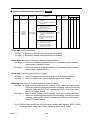
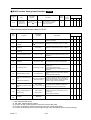
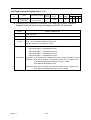
9.4.4 OPTION CARDS
Name
Code No.
Descriptions
Valid Access Levels
Install
Location
GP SL PID PG
MODBUS RTU protocol communication
optional card:
RS-485
z Communication method: Asynchronous
○
Communication 4H300D4560001
z Communication speed: 19.2Kbps
Card SI-M
(max.)
○
╳
╳
2CN
╳
╳
╳
○
3CN
○
╳
○
╳
3CN
○
○
○
╳
3CN
○
○
○
○
2CN
○
○
○
○
2CN
z Interface: RS-232, RS-422, RS-485
Permits compensation of speed variation
caused by slip, by speed feedback using a
pulse generator (PG) provided to the
motor:
z Phase A (signal pulse) input.
PG Speed
Controller Card 3H300D1180009 z PG frequency range: 50 to 65535Hz
FB-C
z Pulse monitor output: +12V, 20mA
z Input Voltage: +12V
External supply
z Input current: 300mA
Outputs pulse train signal corresponding
to the inverter output frequency
Digital pulse
z Output pulse: 1F, 6F, 10F, 12F, 36F
monitor Card 3H331C0060008
(F: output frequency)
PM-C
z Output voltage: +12V ±10% (isolated)
z Output current: 20mA max
Output analog signal for monitoring
inverter output state (output frequency,
output current etc.)
Analog monitor
4H300D3850005 z Output resolution: 11 bits (1/2048)
Card AO-12
z Output voltage: -10 to +10V
(non isolated)
z Output channel: 2 channels
Allows 8 bits digital speed reference set.
z Input signal: binary 8 bits/BCD 2 digits
Digital
+ code
reference Card 4H300D4570006
DI-08
z Input voltage: +24V (isolated)
z Input current: 8mA
Allows bipolar high precision, high
resolution analog speed reference set.
Analog
z Input signal level: 0 to ±10VDC (20KΩ)
reference Card 4H300D4580001
4 to 20mA (250Ω)
AI-14B
3 channels
z Input resolution: 13 bits + code (1/8192)
PART Ⅰ
9-7-
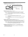
Name
Code No.
Valid Access Levels Install
GP SL PID PG Location
Descriptions
Converts the multi-function analog output
V/I Conversion
21 -○
22 ) signal from 0~10V to
○
3P103D0280001 (terminals ○
card V/I card
4~20mA signal
Outputs isolated type digital signal for
monitoring inverter run state (alarm signal,
zero speed detection etc.)
z Output channel: Photo coupler 6
channels
Digital output
○
(48V, 50mA or less)
card DO-08
Relay contact output 2
channels
250VAC, 1A or less
30VDC, 1A or less
PROFIBUS protocol communication
optional card:
PROFIBUS
z Communication method: Asynchronous
○
Communication
z Communication speed: 19.2Kbps
card GS-P
(max.)
○
○
○
3CN
○
○
╳
3CN
○
○
○
2CN
z Interface: RS-232, RS-422, RS-485
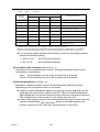
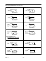
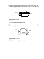
【Installation】Use the following procedure to install these option card.
1>. Turn off the main circuit power supply.
2>. Leave it off for a least one minute before removing the front cover of the
inverter. Check to be sure that the CHARGE indicator is OFF.
3>. Insert the spacer (Which is provided with the option card) into the
spacer hole at the control board.
4>. Pass the spacer through the spacer hole at the option card. Check to
be sure that it is precisely aligned with the 2CN or 3CN position, and
snap it into the proper position.
5> 2CN port and 1CN port are used at the same time by GS-P, so can’t be
work when GS-P is used.
CONTROL PC
BOARD
2CN
3CN
OPERATOR
1CN
CONTROL
TERMINAL
MAIN CIRCUIT TERMINAL
Fig. 8 Option card Installation
PART Ⅰ
9-8-
PART II
OPERATION MANUAL
PART Ⅱ
1-0
1. DESCRIPTION OF USING 7200GS
1.1 Using LCD (or LED) digital operator
z 7200GS are standard with LCD digital operator JNEP-34. Moreover, an LED digital
operator JNEP-33 is also available. Three two digital operator have the same
operation functions except the LCD and 7-segments LED display difference.
z The LCD and LED digital operator has 2 modes: DRIVE mode and PRGM mode.
When the inverter is stopped, DRIVE mode or PRGM mode can be selected by
PRGM
pressing the key DRIVE . In DRIVE mode, the operation is enabled. Instead, in the
PRGM mode, the parameter settings for operation can be changed but the operation
is not enabled.
a> The LCD digital operator component names and functions shown as below:
DRIVE
FWD
REV
REMOTE
SEQ
REF
34
DIGITAL OPERATOR JNEP-31
PRGM
DRIVE
DSPL
operation mode indicators
DRIVE : lit when in DRIVE mode
FWD : lit when there is a forward run command input
REV
: lit when there is a reverse run command input
SEQ
: lit when the run command is enabled from the control
circuit terminal or option card (REMOTE mode)
REF
: lit when the frequency reference from the control circuit
terminals (VIN or AIN) or option card enabled
(REMOTE mode)
LCD Display
Chinese Display: 2 row, each row has 8 characters at most
English Display: 2 row, each row has 20 characters at most
EDIT
JOG
ENTER
FWD
REV
RESET
Keys (Key functions are defined in Table 11)
RUN
STOP
Fig 9 LCD Digital operator component names and functions
b> The LED digital operator component names and functions shown as below:
DRIVE
FWD
REV
REMOTE
SEQ
REF
32
DIGITAL OPERATOR JNEP-31
33
PRGM
DRIVE
DSPL
EDIT
JOG
ENTER
FWD
REV
RESET
RUN
Keys (Key functions are defined in Table 11)
STOP
Fig 10
PART Ⅱ
operation mode indicators
DRIVE : lit when in DRIVE mode
FWD : lit when there is a forward run command input
REV
: lit when there is a reverse run command input
SEQ
: lit when the run command is enabled from the control
circuit terminal or option card (REMOTE mode)
REF
: lit when the frequency reference from the control circuit
terminals (VIN or AIN) or option card enabled
(REMOTE mode)
LED Display
5 digitals 7-degment LED.
LED Digital operator component names and functions
1-1
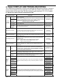
Table 11
Key’s functions
Key
Name
Function
PRGM
DRIVE
PRGM/DRIVE key
Switches between operation (PRGM) and operation
(DRIVE).
DSPL
DSPL key
Display operation status
JOG
JOG key
Enable jog operation from digital operator in operation
(DRIVE).
FWD
REV
FWD/REV key
Select the rotation direction from digital operator.
RESET key
Set the number of digital for user constant settings.
Also it acts as the reset key when a fault has occurred.
INCRENMNT key
Select the menu items, groups, functions, and user
constant name, and increment set values.
DECRENENT key
Select the menu items, groups, functions, and user
constant name, and decrement set values.
ENTER
EDIT/ENTER key
Select the menu items, groups, functions, and user
constants name, and set values (EDIT). After finishing
the above action, press the key (ENTER).
RUN
RUN key
Start inverter operation in (DRIVE) mode when
operator is used. The led will light.
STOP key
Stop 7200GS operation from LCD digital operator. The
key can be enable or disabled by setting a constant
Sn-05 when operating from the control circuit terminal
(in this case, the LED will light).
RESET
EDIT
STOP
RUN, STOP indicator lights or blinks to indicate the 3 operating status:
Inverter
output frequency
變頻器輸出頻率
STOP
RUN
STOP
頻率設定
Frequency
Setting
RUN
STOP
亮燈
ON
PART Ⅱ
閃爍
Blink
1-2
燈熄
OFF
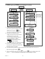
1.2 DRIVE mode and PRGM mode displayed contents
Power on
PRGM
DRIVE
PRGM mode
DSPL
An-□□ monitor
DRIVE mode
*1
*3
DSPL
Frequency reference
set
When faults
Occurred before
power supply
was turned off
DSPL
DSPL
Output Frequency
bn-□□ monitor set
DSPL
Sn-□□ monitor
*2
Output Current
set
DSPL
Cn-□□ monitor
*4
set
Display of faults which
occurred before power supply
was turned off
*1 : When the inverter is put into operation,
DSPL
the inverter system immediately enters into
Un-□□ monitor
DRIVE mode. Press the
PRGM
DRIVE
key,
DSPL
the system will switch into PRGM mode.
*2 : If the fault occurred before power
An-□□ monitor
supply was turned off, the fault contents
set
DSPL
are displayed when power ON.
bn-□□ monitor set
Fault occurrence order and display are
provided by
∧
or
∨
DSPL
key.
Un fault : n =1~4,the fault occurrence
*5
DSPL +
RESET
Sn-□□ monitor
Order, fault :the fault contents,
please refer to page 131~138,the fault display.
DSPL
Cn-□□ monitor
*3 : If no fault occurred before power supply
was turned off , display the monitored data
according to the bn-10 setting
*4 : This block will be by passed if no fault occurred before power supply was turned off or a
fault occurs and was reset by
RESET
*5 : When in the DRIVE mode, press the DSPL key and RESET key, the setting values of Snand Cn-□□ will only be displayed for monitoring but not for changing or setting.
PART Ⅱ
1-3
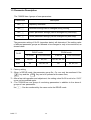
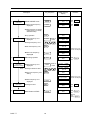
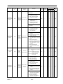
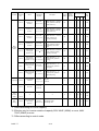
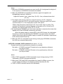
1.3 Parameter Description
The 7200GS has 4 groups of user parameters:
Parameters*4
Description
An-□□
Frequency command
bn-□□
Parameter settings can be changed during running
Sn-□□
System parameter settings (can be changes only after stop)
Cn-□□
Control parameter settings (can be changed only after stop)
The parameter setting of Sn-03 (operation status) will determine if the setting value
of different parameter groups are allowed to be changed or only to be monitored, as
shown below:
DRIVE mode
PRGM mode
Sn-03
*2
To be set
To be monitored
To be set
To be monitored
0000*1
An, bn
Sn, Cn
An, bn, Sn, Cn
-
0101*3
An
bn, Sn, Cn
An
bn, Sn, Cn
*1 : Factory setting
*2 : When in DRIVE mode, the parameter group Sn-, Cn- can only be monitored if the
RESET
key and the
DSPL
key are to be pressed at the same time,
*3 : After a few trial operation and adjustment, the setting value Sn-03 is set to be “0101"
so as not be modified again.
*4 : The 7200GS has one group of monitoring parameters in addition to the above 4
groups of user parameters.
Un-□□ : Can be monitored by the users under the DRIVE mode.
PART Ⅱ
1-4
1.4 Sample example of using LCD digital operator
Note :
Before operation: Control parameter Cn-01 value must be set as the input AC
voltage value. For example, Cn-01=380 if AC input voltage is
380.
This sample example will explain the operating of 7200GAS according to the following
time chart.
■ OPERATION MODE
(1)
(2)
(3)
(4)
(5)
(6)
FWD
60Hz
(7)
(8)
STOP
POWER
ON
FWD JOG
OPERATION
SET INPUT
VOLTAGE
REV RUN
FWD RUN
FREQUENCY
SETTING
REV
60Hz
FREQ REF.
VALUE CHANGE
■ Sample operation
Description
Key Sequence
(1) When POWER ON z Sect frequency reference
Input voltage
setting (e.g. AC
input voltage is
380V)
z Select PRGM mode
PRGM
DRIVE
z Select CONTROL
PARAMETER
DSPL
EDIT
ENTER
z Display Cn-01 setting
RESET
z Input Voltage 380V
(continued)
PART Ⅱ
Remarks
Freq. Cmd. 00.00Hz
TECO
value displayed
(2)
Digital Operator
Display
EDIT
ENTER
1-5
An-01
Freq. Cmd. 1
Press 3
times
LED DRIVE
OFF
Cn-01Input Voltage
Cn-01=440.0V
Input Voltage
Cn-01=380.0V
Input Voltage
Entry Accepted
Display for 0.5
sec
Description
Key Sequence
Digital Operator
Display
Remarks
(continued)
(3)
z Select DRIVE mode
PRGM
DRIVE
z Select output frequency
displayed
DSPL
Freq. Cmd. 00.00Hz
TECO
FWD JOG
Freq. Cmd. .0
TECO
Hz
LED
ON
DRIVE
LED
ON
FWD
z Select direction of rotation
(When power on, initially
defaulted FWD)
z Jog operation
(4)
Frequency setting
z Select frequency cmd
displayed
O/P Freq. 6.00 Hz
TECO
JOG
DSPL
Press 5
times
15Hz
z Change frequency cmd
RESET
z Set new frequency cmd
ENTER
Freq. Cmd. 00.00Hz
TECO
Freq. Cmd. 15.00Hz
TECO
Freq. Cmd. 15.00Hz
TECO
EDIT
Entry Accepted
(5)
FWD run
(6)
Frequency
command change
60Hz
z Select O/P frequency
displayed
DSPL
O/P Freq. .0 Hz
TECO
z Running operation
RUN
O/P Freq. 15.00 Hz
TECO
z Select frequency cmd
displayed
DSPL
z Change reference value
z Enter new frequency cmd
setting
RESET
EDIT
ENTER
Press 5
times
(7)
REV RUN
(8)
STOP
z Change to REV
z Decrement to STOP
DSPL
FWD
REV
STOP
LED
ON
RUN
Freq. Cmd. 15.00Hz
TECO
Freq. Cmd. 60.00Hz
TECO
Freq. Cmd. 60.00Hz
TECO
Entry Accepted
z Select frequency cmd
displayed
Display for 0.5 sec
Confirm the display.
Display for 0.5 sec
Confirm the display.
O/P Freq. 60.00 Hz
TECO
O/P Freq. -60.00 Hz
TECO
LED
ON
REV
O/P Freq. .0 Hz
TECO
LED
ON
STOP
(Blinking
while
RUN
decel.)
PART Ⅱ
1-6
1.5 Control Mode Selection
The 7200GS standard with four selectable control modes:
1 GP: V/F control mode (General Purpose V/F control mode).
○
2 SL: Sensorless Vector Control mode (with motor parameters auto tuning
○
function).
3 PID: PID with Auto Energy Saving Control mode.
○
4 PG: V/F+PG closed loop Control mode.
○
The control mode can be selected by parameter Sn-13:
Sn-13 setting
00
01
10
11
LCD Display (English)
Sn-13=00
Descriptions
GP: V/F control mode (factory setting)
V/F Ctrl Mode
Sn-13=01
SL: Sensorless Vector Control mode
SL Ctrl Mode
Sn-13=10
PID: PID with Auto Energy Saving
Control mode
PID Ctrl Mode
Sn-13=11
PG: V/F+PG closed loop Control mode
PG Ctrl Mode
Caution:
1. Factory setting as V/F control mode (GP mode), When the required control
mode is selected by Sn-13, the selected control mode is effective only after
turning off the power supply till the display of digital operator (LCD or LED
digital operator) is off, then turn on the power supply again.
2. The AUTO TUNE feature can be used to identify and store the important motor
parameters in the first time sensorless vector operation after installation, and
when switching to anyone of the other three control modes, then switched
back to the sensorless vector control mode, the AUTO TUNE feature has to be
used to identify and store the motor parameters once again.
PART Ⅱ
1-7
2. SETTING USER CONSTANT
2.1 Descriptions of constant/function list
■ Formate
Parameter
No.
Name
LCD Display (English)
Change
During
Operation
Setting Range
Setting
Unit
Factory
Setting
Valid Access Levels
GP SL PID PG
Ref.
Page
○
or
╳
■ Descriptions
z Parameter NO.: NO. of the parameter group An-□□, bn-□□, Sn-□□, Cn□□ and Un-□□.
z Name: Parameter function name.
z LCD Display (English): The LCD display contents.
z Change During Operation:
○ : The parameter setting can be changed during running.
╳ : The parameter setting can not be changed during running.
z Setting Range: The allowable setting range of the parameter.
z Setting Unit: The allowable setting unit (“-” means without unit).
z Factory Setting: Some of the parameter have different factory setting value
under different control mode.
z Valid Access Levels:
1 GP: V/F control mode (General Purpose V/F control mode).
○
2 SL: Sensorless Vector Control mode (with auto tuning function).
○
3 PID: PID with Auto Energy Saving Control mode.
○
4 PG: V/F+PG closed loop Control mode.
○
○ : The parameter is access valid under this control mode (i.e. the
parameter group can be monitored or set by the user)
╳ : The parameter is access invalid under this control mode.
Number (1~3): different number with different function definitions.
PART Ⅱ
2-1
2.2 Frequency command (in Multi-speed operation)
An-□ □
Under the DRIVE mode, the user can monitor the parameters and set their values.
Parameter
No.
Name
An-01
Frequency
Command 1
An-02
Frequency
Command 2
Frequency Command 2
An-03
Frequency
Command 3
Frequency Command 3
An-04
Frequency
Command 4
An-05
Frequency
Command 5
An-06
Frequency
Command 6
Frequency Command 6
An-07
Frequency
Command 7
Frequency Command 7
An-08
Frequency
Command 8
An-09
Jog Frequency
Command
LCD Display (English)
An-01=000.00Hz
Frequency Command 1
An-02=000.00Hz
An-03=000.00Hz
An-04=000.00Hz
Frequency Command 4
An-05=000.00Hz
Frequency Command 5
An-06=000.00Hz
An-07=000.00Hz
An-08=000.00Hz
Frequency Command 8
An-09=006.00Hz
Jog Command
Change
During
Operation
Setting Range
Setting
Unit
Factory
Setting
Valid Access Levels
GP SL PID PG
○
0.00~180.00 Hz 0.01Hz 00.00Hz ○
○
○
○
○
0.00~180.00 Hz 0.01Hz
0.00Hz
○
○
○
○
○
0.00~180.00 Hz 0.01Hz
0.00Hz
○
○
○
○
○
0.00~180.00 Hz 0.01Hz
0.00Hz
○
○
○
○
○
0.00~180.00 Hz 0.01Hz
0.00Hz
○
○
╳
╳
○
0.00~180.00 Hz 0.01Hz
0.00Hz
○
○
╳
╳
○
0.00~180.00 Hz 0.01Hz
0.00Hz
○
○
╳
╳
○
0.00~180.00 Hz 0.01Hz
0.00Hz
○
○
╳
╳
○
0.00~180.00 Hz 0.01Hz
6.00Hz
○
○
○
○
Ref.
Page
*1. The displayed "Setting Unit” can be changed through the parameter Cn-20.
*2. At factory setting, the value of "Setting Unit" is 0.01Hz.
*3. The setting of An-01~09 should be with the multi-function analog terminals ○
5 ~○
8 .
PART Ⅱ
2-2
bn-□ □
2.3 Parameters Can Be Changed during Running
Under the DRIVE mode, the Parameter group can be monitored and set by the
users.
Valid Access
Levels
LCD Display
(English)
Change
During
Operation
Setting Range
Acceleration
Time 1
bn-01=0010.0s
Acc. Time 1
○
0.0~6000.0s
0.1s
10.0s
○ ○ ○ ○
bn-02
Deceleration
Time 1
bn-02=0010.0s
Dec. Time 1
○
0.0~6000.0s
0.1s
10.0s
○ ○ ○ ○
bn-03
Acceleration
Time 2
bn-03=0010.0s
Acc. Time 2
○
0.0~6000.0s
0.1s
10.0s
○ ○ ○ ○
bn-04
Deceleration
Time 2
bn-04=0010.0s
Dec. Time 2
○
0.0~6000.0s
0.1s
10.0s
○ ○ ○ ○
bn-05
Analog
Frequency
Cmd. Gain
(Voltage)
bn-05=0100.0%
~Freq. Cmd. Gain
○
0.0~1000.0%
0.1%
bn-06
Analog
Frequency
Cmd. Bias
(Voltage)
bn-06=0000.0%
~Freq. Cmd. Bias
○
-100.0%~100.0%
0.1%
0.0%
○ ○ ○ ○
Torque
Boost
bn-07
Auto Torque
Boost Gain
(Ineffective
in Auto
energy-saving
mode)
bn-07=1.0
Auto_Boost Gain
○
0.0~2.0
0.1
1.0*
1
○ ○ ○ ○
2-5
Motor Slip
bn-08
Rated Slip of
Motor
bn-08 =0.0%
Motor Rated Slip
○
0.0~9.9%*
0.1%
0.0%
1
╳ ╳
2-6
2-7
Energy
Saving
bn-09
Energy Saving
Gain
bn-09=080%
Eg. Saving Gain
○
0~200%
1%
80%
○ ○ ╳ ○
2-7
bn-10
bn-10=1
Monitor No.
After power ON Power On. Contents
○
1~3
1
1
○ ○ ○ ○
2-7
bn-11
Multi-Function
bn-11=1.00
Analog Output
A01 Gain *3 ~Output A01 Gain
○
0.01~2.55
0.01
1.00
bn-12
Multi-Function
bn-12=1.00
Analog Output
~Output
A02 Gain
A02 Gain *3
○
0.01~2.55
0.01
1.00
1
bn-13
PID Detection
Gain
bn-13=01.00
PID Det. Gain
○
0.01~10.00
0.01
1.00
╳ ╳ ○ ╳
bn-14
PID
Proportional
Gain
bn-14=01.0
PID P-Gain
○
0.0~10.0
0.1
1.0
╳ ╳ ○ ╳
bn-15
PID Integral
Gain
bn-15=010.0s
PID I-Time
○
0.0~100.0s
0.1s
10.0s
╳ ╳ ○ ╳
bn-16
PID Differential
Time
bn-16=0.00s
PID D-Time
○
0.00~1.00s
0.01s
0.00s
╳ ╳ ○ ╳
bn-17
PID Bias
bn-17=000%
PID Bias
○
0~109%*
1%
0%
╳ ╳ ○ ╳
Function
Acc/Dec
time
Parameter
No.
Name
bn-01
Analog
Frequency
Command
A01 Gain
A02 Gain
PID
Control
Setting Factory
Unit Setting
GP SL PID PG
Ref.
Page
2-4
100.0% ○ ○ ○ ○
2-5
2
1
2
1
1
2
2-7~2-9
2
1
1
2
2-9
4-9
*1. The factory setting value is 1.2 for SL control mode.
*2. Cn-04 is to be the 100% level.
*3. When AO-12 option card used, bn-11 & bn-12 corresponding to gain of analog signal
AO1 & AO2 of AO-12.
PART Ⅱ
2-3
(1) Acceleration Time 1 (bn-01)
(2) Deceleration Time 1 (bn-02)
(3) Acceleration Time 2 (bn-03)
(4) Deceleration Time 2 (bn-04)
LCD Display
(English)
Change
During
Operation
Setting Range
Acceleration Time 1
bn-01=0010.0s
Acc. Time 1
○
bn-02
Deceleration Time 1
bn-02=0010.0s
Dec. Time 1
bn-03
Acceleration Time 2
bn-04
Deceleration Time 2
Parameter
No.
Name
bn-01
Setting
Unit
Factory
Setting
0.0~6000.0s
0.1s
○
0.0~6000.0s
bn-03=0010.0s
Acc. Time 2
○
bn-04=0010.0s
Dec. Time 2
○
Valid Access Levels
GP
SL
PID PG
10.0s
○
○
○
○
0.1s
10.0s
○
○
○
○
0.0~6000.0s
0.1s
10.0s
○
○
○
○
0.0~6000.0s
0.1s
10.0s
○
○
○
○
z Set individual Acceleration / Deceleration times
z Acceleration time: the time required to go from 0% to 100% of the maximum output
frequency.
z Deceleration time: the time required to go from 0% to 100% of the maximum output
frequency.
z If the acceleration / deceleration time sectors 1 and 2 are input via the multifunction
5 ~○
8 , the acceleration / deceleration can be switched between 2
inputs terminal ○
sectors even in the running status.
Output frequency
5 ~○
8
Control circuit terminals ○
Open select the 1st sector Acc. / Dec. time
(Parameters bn-01, bn-02 set)
Cn-02
Close select the 2nd sector Acc. / Dec. time
(Parameters bn-03, bn-04 set)
bn-01
bn-03
Time
bn-02
bn-04
Note:
1. To set the S-curve characteristics function, please refer to Sn-06.
PART Ⅱ
2-4
(5) Analog Frequency Cmd. Gain (Voltage) (bn-05)
(6) Analog Frequency Cmd. Bias (Voltage) (bn-06)
Parameter
No.
Name
LCD Display
(English)
Change
During
Operation
Setting Range
Setting
Unit
Factory
Setting
Valid Access Levels
GP
SL PID PG
bn-05
Analog Frequency
Cmd. Gain (Voltage)
bn-05=0100.0%
~Freq. Cmd. Gain
○
0.0~1000.0%
0.1%
100.0%
○
○
○
○
bn-06
Analog Frequency
Cmd. Bias (Voltage)
bn-06=0000.0%
~Freq. Cmd. Bias
○
-100.0%~100.0%
0.1%
0.0%
○
○
○
○
z bn-05: The input level when frequency reference voltage is 10V is set in units of 1%,
examples are shown below.
z bn-06: The input level when frequency reference voltage is 0V is set in units of 1%
FREQUENCY
REF.
%
bn-05
<Example>
1 bn-05 = 50.0
○
2 a: bn-06 = 10.0
○
bn-06
(a)
b: bn-06 = -10.0
bn-06 is positive value.
bn-06 is
negative value.
10
0
0V
10V
INPUT LEVEL
bn-06
(b) -10
(7) Auto Torque Boost Gain (bn-07)
Parameter
No.
Name
LCD Display
(English)
Change
During
Operation
Setting Range
Setting
Unit
Factory
Setting
bn-07
Auto Torque Boost Gain
(Ineffective in Auto
energy-saving mode)
bn-07=1.0
Auto_Boost Gain
○
0.0~2.0
0.1
1.0
Valid Access Levels
GP
SL
○
○
PID PG
○
○
z The inverter can increase the output torque to compensate the load increase
automatically through the auto torque boost function. Then the output voltage will
increase. As a result, the fault trip cases can be decreased. The energy efficiency is
also improved. In the case that the wiring distance between the inverter and the
motor is too long (e.g. more than 100m), the motor torque is a little short because of
voltage drop. Increase the value of bn-11 gradually and make sure the current will
not increase too much. Normally, no adjustment is required.
100%
torque
increase
Output
voltage
torque
decrease
Base frequency
※ bn-07 is ineffective when the Auto-Energy Saving function is effective (Sn-08=X1XX)
in the PID control mode (Sn-13=10).
PART Ⅱ
2-5
(8) Rated Slip of Motor (bn-08)
1. GP
Name
LCD Display
(English)
Change
During
Operation
Setting Range
Setting
Unit
Factory
Setting
Rated Slip of Motor
bn-08 =0.0%
Motor Rated Slip
○
0.0~9.9%
0.1%
0.0%
Parameter
No.
bn-08
Valid Access Levels
GP
1
SL PID PG
2
╳
╳
z Motor rated slip is set in units of 0.1%
TORQUE
f1
SMALL LOAD
Simplified speed control is performed
without encoder (PG or TG).
With frequency offset f1 to f2, speed
fluctuation due to load is reduced.
f2
LARGE LOAD
LOAD TORQUE
SPEED
z When the output current of the inverter is larger than motor no-load current (Cn-34),
the output frequency of the inverter is compensated.
z The amount of frequency compensation is determined by the formula below. The
maximum voltage frequency (Cn-04) is 100%.
z If the output current is equal to the motor rated current (Cn-09), the output frequency is
compensated for by the motor rated slip (bn-08).
z If frequency reference is equal to or smaller than minimum output frequency (Cn-07)
or motor is in a regeneration mode, slip compensation is not performed.
z The amount of output frequency compensation in a constant torque area and a
constant output area is shown in the figure below.
Amount of output frequency compensation =
motor rated slip
motor rated motor no-load
-
current
current
×
output
- motor no-load
current
current
Cn-04xbn-08
bn-08
Cn-02
Cn-04
Motor rated current: Cn-09
Motor no-load current: Cn-34
Motor rated slip:
bn-08
z When 0.0 is set in bn-08, output frequency compensation is not performed.
PART Ⅱ
2-6
2. SL
Parameter
No.
Name
LCD Display
(English)
Change
During
Operation
Setting Range
Setting
Unit
Factory
Setting
bn-08
Rated Slip of Motor
bn-08 =1.7Hz
Motor Rated Slip
○
0.0~20.0Hz
0.1Hz
1.7Hz*
Valid Access Levels
GP
1
SL PID PG
2
╳
╳
* Factory setting depending on inverter capacity (Sn-01 set value)
z To calculate the motor rated slop by the below equation:
Motor Rated Slop (Hz)= [rated speed (rpm)-nameplate full load speed (rpm)]
×
P
(Hz)
120
P=motor poles
(9) Energy Saving Gain (bn-09)
Parameter
No.
Name
LCD Display
(English)
Change
During
Operation
Setting Range
Setting
Unit
Factory
Setting
bn-09
Energy Saving Gain
bn-09=080%
Eg. Saving Gain
○
0~200%
1%
80%
Valid Access Levels
GP
SL PID PG
○
○
╳
○
z Input the energy-saving operation command (Sn-15~18=63), While a light load causes
the inverter output voltage to be reduced and save energy. Set this value as a
percentage of the V/F pattern. The setting range is 0~200%. The energy saving
function is disabled when energy saving gain (bn-09) is 100%.
z Please refer to page 2-56, the time chart when energy-saving operation command is
input.
(10) Monitor No. after Power ON (bn-10)
Parameter
No.
bn-10
Name
LCD Display (English)
Change
During
Operation
Setting Range
Setting
Unit
Factory
Setting
Monitor No. After
power ON
bn-10=1
Power On. Contents
○
1~3
1
1
Valid Access Levels
GP
SL PID PG
○
○
○
z Data to be monitored after turning on power supply is selected with constant NO.
bn-10=1:Frequency reference
bn-10=2:Output frequency
bn-10=3:Output current
(11) Multi-function Analog Output A01 Gain (bn-11)
(12) Multi-function Analog Output A02 Gain (bn-12)
PART Ⅱ
2-7
○
1. GP, SL, PID
Parameter
No.
Name
LCD Display
(English)
Change
During
Operation
Setting Range
Setting
Unit
Factory
Setting
bn-11
Multi-Function Analog
Output A01 Gain
bn-11=1.00
~Output A01 Gain
○
0.01~2.55
0.01
1.00
1
1
1
2
bn-12
Multi-Function Analog
Output A02 Gain
bn-12=1.00
~Output A02 Gain
○
0.01~2.55
0.01
1.00
1
1
1
2
Valid Access Levels
GP
SL PID PG
z To set the output voltage level of A01 channel of analog monitor optional card (AO-12)
by bn-11 and bn-12. The output voltage level is set in the form of 10V×bn-11 (or
bn-12).
Channel 1
(Select item to be output
from channel 1 by Sn-28)
10.0V × bn-11
Channel 1 (A01)
of AO-12 card
Channel 2
(Select item to be output
from channel 2 by Sn-28)
10.0V × bn-12
Channel 2 (A02)
of AO-12 card
21 .
z To set the output voltage level of multi-function analog output terminal ○
The output voltage level is set in the form of 10V×bn-11
21
Multi-function analog output terminal ○
(Select item to be output from terminal
21 by the 4th digit of Sn-05 and the 2nd
○
digit of Sn-09)
21
Terminal ○
10.0V × bn-11
2. PG
Parameter
No.
Name
LCD Display
(English)
Change
During
Operation
Setting Range
Setting
Unit
Factory
Setting
bn-11
Multi-Function Analog
21 items
Output ○
bn-11=2
Output Frequency
○
1~13
-
2
1
1
1
2
bn-12
Multi-Function Analog
21 Gain
Output ○
bn-12=
∼Output Gain
○
0.01~2.55
0.01
0.5
1
1
1
2
Valid Access Levels
GP
SL PID PG
21
z bn-11: Select the item to be output from terminal ○
bn-11 setting LCD Display (English)
01
Freq. Cmd.
02
O/P Freq.
03
O/P I
04
O/P V
05
DC Volt
06
O/P KW
07-11
Reserved
12
Sp. FBK
13
Sp. Compen.
PART Ⅱ
2-8
Functions
Frequency Command (Reference)
Output Frequency
Output Current
Output Voltage
DC Voltage
Output Power (KW)
Not used
Amount of speed feedback
Amount of speed control compensation
21 .
z bn-12: To set the output voltage level of multi-function analog output terminal ○
The output voltage level is set in the form of 10V×bn-12
21
Multi-function analog output ○
(Select item to be output from
21 by bn-11)
terminal ○
10.0V × bn-12
21
Terminal ○
※ The analog monitor optional card (AO-12) can not be used in PG control mode.
(13) PID Control function (bn-13~bn-17)
z Please refer to Appendix C “PID CONTROL”.
PART Ⅱ
2-9
2.4 System Parameters
Sn-□ □
Function
Parameter
No.
Name
LCD Display
(English)
Capacity
Setting
Sn-01
Inverter
Capacity
Selection
Sn-01=29
440V 25HP
V/F Curve
Sn-02
V/F Curve
Selection
Sn-02=01
V/F Curve
Display of
Operator
Operator
Status
Sn-03
Description
Factory
Setting
Change Valid Access Levels
During
Operation GP SL PID PG
Ref.
Page
Inverter Capacity Selection
*1
╳
1
2
1
1
2-14~
2-21
V/F pattern Selection
01
╳
○
╳
○
○
2-22~
2-24
0000
╳
○
○
○
○
2-25
0011
╳
○
○
○
○
2-26~
2-28
0000
╳
1
1
1
2
2-29~
2-30
0000
╳
○
○
○
○
2-31~
2-33
0000: Setting and reading of An-□
□, Bn-□□,Cn-□□, Sn-□
□ enabled
0101: Setting and reading of An-□
□, Readinng of Bn-□
Sn-03=0000
□,Cn-□□, Sn-□□
Operate Setting
enabled
1110: Constants Initialigation
(2-wire)*2
1111: Constants Initialigation
(3-wire)*2
Constants
Initialization
- - -0: Frequency Command =
13
Control circuit terminals ○
Operation Mode
Select
Operation
Mode
Select 1
Sn-04=0011
Sn-04
Stopping Method
Stopping
Method
Selection
14
or ○
- - -1: Frequency Command =
Frequency Command 1
(An-01)
- -0 -: RUN.STOP Command =
Control circuit terminals
- -1 -: RUN.STOP Command =
LCD Digital Operator
00- -: Stopping method = Ramp to
stop
01- -: Stopping method =Coasting
to stop
10- -: Stopping method =Full-range
DC injection branking stop
11- -: Stopping method = Coasting
stop (timer function
provided)
- - -0: Stop key effective during
operation from control
terminal
- - -1: Stop key effective during
operation from control
terminal
- -0 -: Reverse run enabled
- -1 -: Reverse run disabled
Operation
Mode
Select 2
Sn-05
I/O terminal
function
selection
1
- 0- -: Control input terminals ○
Sn-05=0000
I/O term. Fct
8 are scanned twice.
~○
1
- 1- -: Control input terminals ○
8 are scanned once.
~○
0- - -: Selection of item to be
analog output (terminals
21 , ○
22 )*3
○
1- - -: Selection of item to be
analog output (terminals
21 , ○
22 )*3
○
- -00: S curve=0.2sec
- -01: S curve=0.0sec (NO S
curve)
- -10: S curve=0.5sec
- -11: S curve=1.0sec
Operation
Mode
Select 3
Sn-06
S-curve and
frequency
Command
characteristics
-0 - -: Reference command has
forward characteristics
(0-10V or 4-20mA/0~100%)
Sn-06=0000
-1 - -: Reference command has
S-curve Cmd. Char.
reverse characteristics
(0-10V or 4-20mA/100~0%)
0- - -: Stop by reference input when
frequency reference is
missing
1- - -: Operation to continue with
80% of frequence reference
when frequency reference
is missing
PART Ⅱ
2-10
Function
Parameter
No.
Name
LCD Display
(English)
Description
Factory
Setting
Change Valid Access Levels Ref.
During
Page
Operation GP SL PID PG
- - -0: Overtorque detection disabled
- - -1: Overtorque detection enabled
- -0 -: Enabled only if at agreed
frequency
- -1 -: Enable during operation
(except during DC injection)
Operation
Mode Select 4
Sn-07
Overtorque
Detection
Sn-07=0000
- 0- -: Operation continued after
Over Tq. Detect
overtorque is detected
0000
╳
1
2
1
1
0100
╳
1
1
2
3
0000
╳
1
2
3
╳
0000
╳
○
○
○
○
2-34~
2-35
- 1- -: Coasts to stop if overtorque is
detected
0- - -: Overtorque detection with
current
1- - -: Overtorque detection with
torque
- - -0: Frequency reference input by
option card (AI-14B, DI-08 or
SI-M)
- - -1: Frequency reference input by
digital operetor or control
cirauit input terminals
Operation
Mode Select 5
Sn-08
Option
Card/Invater
Function
Selection
- -0 -: RUN/STOP command input by
option card (AI-14B, DI-08 or
SI-M)
- -1 -: RUN/STOP command input by
Sn-08=0100
digital operator or control
AI/DI & SI-M Card
circuit input terminals
2-36~
2-37
00- -: SI-M communication fault,
deceleration to stop (bn-02)
01- -: SI-M communication fault,
coast to stop
10- -: SI-M communication fault,
deceleration to stop (bn-04)
11- -: SI-M communication fault,
continue to run
- - -0: Analog output (tereminal
21 -○
22 ) depends on Sn-05 4th
○
digit and Sn-09 2nd digit.
- - -1: Analog output (tereminal
21 -○
22 ) is set by SI-M card.
○
- -0 -: Analog output (tereminal
Operation
Mode Select 6
Sn-09
Analog Output
Selection and
Slip
Compensetion
Sn-09=0000
~Output Select
21 -○
22 )
○
- -1 -: Analog output (tereminal
21 -○
22 )
○
2-38~
2-39
- 0- -: Not used
- 1- -: Not used
0- - -: No slip compensation during
regenerating
1- - -: Slip compensation even during
regenerating
- - -0: Stall prevention during
acceleration enabled
- - -1: Stall prevention during
acceleration disabled
Protective
Characteristic
Select 1
Sn-10
Stall
Prevention
Sn-10=0000
Stall Select
- -0 -: Stall prevention during
deceleration enabled
- -1 -: Stall prevention during
deceleration disabled
- 0- -: Stall prevention during running
enabled
- 1- -: Stall prevention during running
disabled
0- - -: Decel time during stall
prevention (bn-02 set value)
1- - -: Decel time during stall
prevention (bn-04 set value)
PART Ⅱ
2-11
2-40~
2-41
Function
Parameter
No.
Name
LCD Display
(English)
Description
Factory
Setting
Change Valid Access Levels
Ref.
During
Page
Operation GP SL PID PG
- - -0: Not used
- - -1: Not used
- -0 -: Fault contact is not energized
during Retry operation
Protective
Characteristic
Select 2
Sn-11
- -1 -: Fault contact is energized
during Retry operation
Retry and
Sn-11=0000
momentary
power loss Retry & Ride -Thru -0 - -: Operation stopped by
protection
momentary power loss
detection (UV1)
0000
╳
○
○
○
○
2-42
0100
╳
○
○
○
○
2-43
00
╳
○
○
○
○
2-44
0000
╳
○
○
○
○
2-45
-1 - -: Operation conticues after
momentary power loss
0- - -: Not used
1- - -: Not used
- - -0: External fault input (terminal
3 ) is NO-contact input
○
- - -1: External fault input: is
NC-contact input
- -0 -: External fault signal: always
detected
Protective
Characteristic
Select 3
Sn-12
External
Fault
Function
Selection
- -1 -: External fault signal: detected
during running only
Sn-12=0100
External Fault
00- -: External fault detected: ramp to
stop (major fault) by bn-02 set
value
01- -: External fault detected:
Coasting to stop (major fault)
10- -: External fault detected: ramp to
stop (major fault) by bn-04
set value
11- -: External fault detected:
opeation to continue (major
fault)
- -00: GP-V/F Control mode
Control Mode
Select
Sn-13
Control
Mode
Select
Sn-13=00
V/F Ctrl mode
- -01: SL-Sensorless Vector Control
mode
- -10: PID-PID With Auyo Energy
Soving Control mode
- -11: PG-V/F+PG closed loop
Control mode
- - -0: Motor overload (OL1)
protection: effective
- - -1: Motor overload (OL1)
protection: ineffective
- -0 -: Motor overload protection:
standard motor
- -1 -: Motor overload protection:
Inverter duty motor
Protective
Characteristic
Select 4
Sn-14
Electronic
Thermal
Overload
Protection
Sn-14=0000
Over Load
Select
- 0- -: Motor overload protection time
constants are standard time (8
minutes)
- 1- -: Motor overload protection time
constants are short-time (5
minutes)
0- - -: Inverter overload (OL2)
protection 103% continuous,
150% for one minute*2
1- - -: Inverter overload (OL2)
protection 113% continuous,
123% for one minute*2
PART Ⅱ
2-12
Function
Parameter
No.
Name
LCD Display
(English)
Description
Factory
Setting
Change
During
Operation
Valid Access Levels
GP
SL
Ref.
Page
PID PG
Sn-15
5
Terminal ○
Function
5 function
00 Selects terminal ○
~ (factory preset for multi-step
Term.5 Function 66
speed reference 1)
03
╳
○
○
○
○
2-46
Sn-16
6
Terminal ○
Function
6 function
00 Selects terminal ○
~ (factory preset for multi-step
Term.6 Function 66
speed reference 2)
04
╳
○
○
○
○
2-46
Sn-17
7
Terminal ○
Function
7 function
00 Selects terminal ○
~ (factory preset for jog
Term.7 Function 66
frequency reference)
06
╳
○
○
○
○
2-46
Sn-18
8
Terminal ○
Function
8 function
Selects terminal ○
00
~ (factory preset for external
Term.8 Function 66 baseblock by NO contact
input)
08
╳
○
○
○
○
2-46
Sn-19
Multi-function
analog input
16 )
(Terminal ○
00
╳
○
○
○
○
2-57
MultiFunction
Select
Sn-15=03
Sn-16=04
Sn-17=06
Sn-18=08
Sn-19=00
Multi-Fct
Input
16 function
00 Selects terminal ○
~ (factory preset for auxilary
0B frequency command)
Sn-20
Multi-function
9 - ○
10
00 Selects terminal ○
Sn-20=00
contact output
~ function (factory preset for
9 -○
10 ) Term. 9 Function 0E running)
(Terminal ○
00
╳
○
○
○
○
2-59
Sn-21
Multi-function PHC
output (Terminal
25 -○
27 )
○
25 - ○
27
00 Selects terminal ○
~ function (factory preset for
0E zero speed)
01
╳
○
○
○
○
2-59
Sn-22
Multi-function PHC
output (Terminal
26 -○
27 )
○
26 - ○
27
00 Selects terminal ○
~ function (factory preset for
0E Agreed frequency)
02
╳
○
○
○
○
2-59
Language
Sn-23
LCD Language
selection
0
╳
○
○
○
○
2-62
-
Sn-24
Not used
-
-
-
-
-
-
-
-
Option
Card
Function
Select
Sn-25
*3
*3
╳
1
2
3
4
○
╳
╳
○
╳
╳
Autotuning
~
Sn-21=01
Term. 25 Function
Sn-22=02
Term. 26 Function
Sn-23=0
0: English
Language: English
1: Chinese
Sn-24=00
Reserved
*3
*3
Motor parameters
Auto tuning
Selection
Motor Auto Test
Sn-28
Sn-29
Sn-29=0
0: Autotuning invalid
1: Autotuning valid
*1. Differs according to inverter capacity.
*2. Effective only for inverter models of capacity 220V 40HP (30KW) or more, 440V
75HP (55KW) or more.
*3. Differs according to control mode.
PART Ⅱ
2-13
2-63
4-16
2-67
▓ Inverter Capacity Selection
Sn-01
Inverter capacity has been preset at the factory. However, if a spare control board is
used, reset the inverter capacity referring to the table below. Control constant Cn- □□
factory setting values (initial values) differ according to Sn-01 setting.
1. GP, PID, PG
Parameter
No.
Name
LCD Display
(English)
Sn-01
Inverter Capacity
Selection
Sn-01=29
440V 25HP
Description
Inverter Capacity Selection
Factory
Setting
Change During
Operation
*1
╳
Valid Access Levels
GP
SL
PID
PG
1
2
1
1
Inverter Capacity Selection
220V Class
Data of Sn-01
Name
01
02
03
04
05
06
07
Inverter rating
HP
0.5
1
2
3
5
7.5
10
15
Inverter rated capacity
kVA
1.4
2.1
2.7
4.1
6.9
10.3
13.7
20.6
Max. applicable motor capacity
Factory Setting
0.5
1
2
3
5
7.5
10
15
(0.4)
(0.75)
(1.5)
(2.2)
(3.7)
(5.5)
(7.5)
(11)
A
3.2
4.8
6.4
9.6
16
24
32
48
A
1.9
3.4
6.1
8.7
13.5
20.1
25.1
36.7
HP (kW)
Inverter rated current
PART Ⅱ
00
Cn-09
Motor rated current
Cn-23
Carrier frequency upper
limit
kHz
15.0
15.0
15.0
15.0
15.0
15.0
15.0
15.0
Cn-24
Carrier frequency lower
limit
kHz
15.0
15.0
15.0
15.0
15.0
15.0
15.0
15.0
Cn-25
Carrier frequency
proportional gain
0
0
0
0
0
0
0
0
Cn-31
Motor phase-to-phase
resistance
2.407
1.583
0.684
0.444
0.288
0.159
Cn-32
Torque compensation iron
loss
W
48
64
108
142
208
252
285
370
Cn-33
Torque compensation limit
V
50
50
50
50
50
50
50
50
Cn-37
Momentary power loss
assurance time
s
0.7
1.0
1.0
1.0
2.0
2.0
2.0
2.0
Cn-40
Minimum baseblock time
s
0.5
0.5
0.5
0.5
0.5
0.7
0.7
0.7
Cn-41*
V/F during speed search
%
100
100
100
100
100
100
100
100
Ω
11.760 5.732
2-14
Inverter Capacity Selection
220V Class
Data of Sn-01
Name
08
09
0A
0B
0C
0D
0E
0F
Inverter rating
HP
20
25
30
40
50
60
75
100
Inverter rated capacity
kVA
27.4
34
41
54
68
78
95
130
Max. applicable motor capacity
Inverter rated current
Factory Setting
20
25
30
40
50
60
75
100
(15)
(18.5)
(22)
(30)
(37)
(45)
(55)
(75)
A
64
80
96
130
160
183
224
300
A
50.3
62.9
72.9
96.7
124
143.5
183.5
230
HP (kW)
Cn-09
Motor rated current
Cn-23
Carrier frequency upper
limit
kHz
15.0
15.0
15.0
10.0
10.0
3.0
*
3.0
*
3.0
*
Cn-24
Carrier frequency lower
limit
kHz
15.0
15.0
15.0
10.0
10.0
3.0
*
3.0
*
3.0
*
Cn-25
Carrier frequency
proportional gain
0
0
0
0
0
0
0
0
Cn-31
Motor phase-to-phase
resistance
0.109
0.077
0.060
0.041
0.033
0.028
0.019
0.007
Cn-32
Torque compensation iron
loss
W
471
425
582
536
641
737
790
1800
Cn-33
Torque compensation limit
V
50
50
50
50
50
50
50
50
Cn-37
Momentary power loss
assurance time
s
2.0
2.0
2.0
2.0
2.0
2.0
2.0
2.0
Cn-40
Minimum baseblock time
s
0.7
1.0
1.0
1.0
1.0
1.0
1.0
1.0
Cn-41*
V/F during speed search
%
100
100
100
80
80
80
80
80
Ω
* The allowable maximum carrier frequency is 10kHz
* In PG mode, the function of Cn-41 is disabled.
PART Ⅱ
2-15
Inverter Capacity Selection
440V Class
Data of Sn-01
20
21
22
23
24
25
26
27
28
29
2A
HP
0.5
1
2
3
5
7.5
10
15
20
25
30
kVA
1.4
2.1
3.4
4.1
6.9
10.3
13.7
20.6
27.4
34
41
Name
Inverter rating
Inverter rated capacity
Max. applicable motor capacity
HP (kW)
Factory Setting
Inverter rated current
A
1
2
3
5
7.5
10
15
20
25
30
(0.75)
(1.5)
(2.2)
(3.7)
(5.5)
(7.5)
(11)
(15)
(18.5)
(22)
1.6
2.6
4.0
4.8
8
12
16
24
32
40
48
1.0
1.7
2.9
4.0
6.8
10.1
12.6
18.6
24.8
31.1
36.3
Cn-09
Motor rated current
Cn-23
Carrier frequency upper
limit
kHz
15.0
15.0
15.0
15.0
15.0
15.0
15.0
15.0
15.0
10.0
10.0
Cn-24
Carrier frequency lower
limit
kHz
15.0
15.0
15.0
15.0
15.0
15.0
15.0
15.0
15.0
10.0
10.0
Cn-25
Carrier frequency
proportional gain
0
0
0
0
0
0
0
0
0
0
0
Cn-31
Motor phase-to-phase
resistance
Cn-32
Torque compensation iron
loss
W
48
64
108
142
208
252
285
370
471
425
582
Cn-33
Torque compensation limit
V
100
100
100
100
100
100
100
100
100
100
100
Cn-37
Momentary power loss
assurance time
s
1.0
1.0
1.0
1.0
2.0
2.0
2.0
2.0
2.0
2.0
2.0
Cn-40
Minimum baseblock time
s
0.5
0.5
0.5
0.5
0.5
0.7
0.7
0.7
0.7
1.0
1.0
Cn-41*
V/F during speed search
%
100
100
100
100
100
100
100
100
100
100
100
PART Ⅱ
A
0.5
(0.4)
Ω
47.02 22.929 9.629 6.333 2.735 1.776 1.151 0.634 0.436 0.308 0.239
2-16
Inverter Capacity Selection
440V Class
Data of Sn-01
Name
Inverter
HP
rating
Inverter rated capacity
Max. applicable motor capacity
(kW)
kVA
HP
Factory Setting
Inverter rated current
A
2B
2C
2D
2E
2F
30
31
32
33
34
35
36
40
50
60
75
100
125
150
175
215
250
300
400
54
68
82
110
138
180
195
230
260
290
385
514
215
250
300
400
40
50
60
75
100
(30)
(37)
(45)
(55)
(75)
64
80
96
128
165
192
224
270
300
340
450
600
145
175
205
235
290
348
465
125
150
(110)
175
(160) (185) (220) (300)
Cn-09
Motor rated current
A
48.7
59.0
70.5
80
114
Cn-23
Carrier frequency upper
limit
kHz
10.0
10.0
10.0
10.0
3.0
*
3.0
*
3.0
*
3.0
*
3.0
*
2.0
2.0
2.0
Cn-24
Carrier frequency lower
limit
kHz
10.0
10.0
10.0
10.0
3.0
*
3.0
*
3.0
*
3.0
*
3.0
*
2.0
2.0
2.0
Cn-25
Carrier frequency
proportional gain
0
0
0
0
0
0
0
0
0
Cn-31
Motor phase-to-phase
resistance
Ω
0.164 0.133
0.110 0.074 0.027 0.051 0.036 0.032
0.023
0.020
0.022
0.014
Cn-32
Torque compensation iron
loss
W
536
641
737
790
1800 1840 2900 2450 2500 2600 1850 3600
Cn-33
Torque compensation limit
V
100
100
100
100
100
100
100
100
100
100
100
100
Cn-37
Momentary power loss
assurance time
2.0
2.0
2.0
2.0
2.0
2.0
2.0
2.0
2.0
2.0
2.0
2.0
Cn-40
Minimum baseblock time s
1.0
1.0
1.0
1.0
1.0
1.0
2.0
2.0
2.0
2.0
2.0
2.0
Cn-41*
V/F during speed search
%
100
100
100
80
80
80
80
80
80
80
80
80
s
0
0
0
* The allowable maximum carrier frequency of 440V class 100HP to 215HP are to be
as follows:
440V Horse Power
100HP
125HP
150HP
175HP
215HP
Max. Allowable Carrier Frequency
8kHz
6kHz
6kHz
5kHz
10kHz
* In PG mode, the function of Cn-41 is disabled.
PART Ⅱ
2-17
2. SL
Parameter
No.
Name
LCD Display
(English)
Sn-01
Inverter Capacity
Selection
Sn-01=29
440V 25HP
Description
Inverter Capacity Selection
Factory
Setting
Change During
Operation
*1
╳
Valid Access Levels
GP
SL
PID
PG
1
2
1
1
Inverter Capacity Selection
220V Class
Data of Sn-01
Name
01
02
03
04
05
06
07
Inverter rating
HP
0.5
1
2
3
5
7.5
10
15
Inverter rated capacity
kVA
1.4
2.1
2.7
4.1
6.9
10.3
13.7
20.6
Max. applicable motor capacity
HP (kW)
0.5
1
2
3
5
7.5
10
15
(0.4)
(0.75)
(1.5)
(2.2)
(3.7)
(5.5)
(7.5)
(11)
Inverter rated current
A
3.2
4.8
6.4
9.6
16
24
32
48
Cn-09
Motor rated current
A
1.9
3.4
6.1
8.7
13.5
20.1
25.1
36.7
Cn-23
Carrier frequency upper
limit
kHz
15.0
15.0
15.0
15.0
15.0
15.0
15.0
15.0
Cn-24
Carrier frequency lower
limit
kHz
15.0
15.0
15.0
15.0
15.0
15.0
15.0
15.0
Cn-25
Carrier frequency
proportional gain
0
0
0
0
0
0
0
0
Cn-31
Motor phase-to-phase
resistance
11.760 5.732
2.466
1.600
0.707
0.398
0.222
0.230
Cn-32
Motor leakage inductance
mH
42.24
19.07
13.40
9.81
6.34
4.22
2.65
2.23
Cn-33
Torque limit
150
150
150
150
150
150
150
150
Cn-37
Momentary power loss
assurance time
s
0.7
1.0
1.0
1.0
2.0
2.0
2.0
2.0
Cn-40
Minimum baseblock time
s
0.5
0.5
0.5
0.5
0.5
0.7
0.7
0.7
Cn-41
V/F during speed search
%
100
100
100
100
100
100
100
100
bn-08
Rated slip of motor
Hz
2.9
2.5
2.6
2.9
3.3
1.5
1.3
1.7
Factory Setting
PART Ⅱ
00
Ω
%
2-18
Inverter Capacity Selection
220V Class
Data of Sn-01
Name
08
09
0A
0B
0C
0D
0E
0F
Inverter rating
HP
20
25
30
40
50
60
75
100
Inverter rated capacity
kVA
27.4
34
41
54
68
78
95
130
Max. applicable motor capacity
HP (kW)
20
25
30
40
50
60
75
100
(15)
(18.5)
(22)
(30)
(37)
(45)
(55)
(75)
A
64
80
96
130
160
183
224
300
Cn-09
Motor rated current
A
50.3
62.9
72.9
96.7
124
143.5
183.5
230
Cn-23
Carrier frequency upper
limit
kHz
15.0
10.0
10.0
10.0
10.0
3.0
*
3.0
*
3.0
*
Cn-24
Carrier frequency lower
limit
kHz
15.0
10.0
10.0
10.0
10.0
3.0
*
3.0
*
3.0
*
Cn-25
Carrier frequency
proportional gain
0
0
0
0
0
0
0
0
Cn-31
Motor phase-to-phase
resistance
0.138
0.102
0.080
0.067
0.045
0.035
0.028
0.019
Cn-32
Motor leakage inductance
mH
1.48
1.39
1.15
1.15
1.15
1.15
1.15
1.15
Cn-33
Torque limit
150
150
150
150
150
150
150
150
Cn-37
Momentary power loss
assurance time
s
2.0
2.0
2.0
2.0
2.0
2.0
2.0
2.0
Cn-40
Minimum baseblock time
s
0.7
1.0
1.0
1.0
1.0
1.0
1.0
1.0
Cn-41
V/F during speed search
%
100
100
100
80
80
80
80
80
bn-08
Rated slip of motor
Hz
1.6
1.7
1.7
1.8
1.3
1.6
1.5
1.4
Factory Setting
Inverter rated current
Ω
%
*The allowable maximum carrier frequency is 10kHz
PART Ⅱ
2-19
Inverter Capacity Selection
440V Class
Data of Sn-01
20
21
22
23
24
25
26
27
28
29
2A
HP
0.5
1
2
3
5
7.5
10
15
20
25
30
kVA
1.4
2.1
3.4
4.1
6.9
10.3
13.7
20.6
27.4
34
41
Name
Inverter rating
Inverter rated capacity
Max. applicable motor capacity
HP (kW)
Factory Setting
Inverter rated current
A
1
2
3
5
7.5
10
15
20
25
30
(0.75)
(1.5)
(2.2)
(3.7)
(5.5)
(7.5)
(11)
(15)
(18.5)
(22)
1.6
2.6
4.0
4.8
8
12
16
24
32
40
48
1.0
1.6
3.1
4.2
7
10.1
12.6
18.6
24.8
31.1
36.3
Cn-09
Motor rated current
Cn-23
Carrier frequency upper
limit
kHz
15.0
15.0
15.0
15.0
15.0
15.0
15.0
15.0
15.0
10.0
10.0
Cn-24
Carrier frequency lower
limit
kHz
15.0
15.0
15.0
15.0
15.0
15.0
15.0
15.0
15.0
10.0
10.0
Cn-25
Carrier frequency
proportional gain
0
0
0
0
0
0
0
0
0
0
0
Cn-31
Motor phase-to-phase
resistance
Cn-32
Motor leakage inductance
mH
Cn-33
Torque limit
%
Cn-37
Momentary power loss
assurance time
s
Cn-40
Minimum baseblock time
Cn-41
V/F during speed search
bn-08
Rated slip of motor
PART Ⅱ
A
0.5
(0.4)
Ω
47.02 22.929 9.629 6.333 2.735 1.776 1.151 0.634 0.436 0.308 0.239
168.7 80.76 53.25 40.03 24.84 16.87 10.59
8.93
5.90
5.54
4.59
150
150
150
150
150
150
150
150
150
150
150
1.0
1.0
1.0
1.0
2.0
2.0
2.0
2.0
2.0
2.0
2.0
s
0.5
0.5
0.5
0.5
0.5
0.7
0.7
0.7
0.7
1.0
1.0
%
100
100
100
100
100
100
100
100
100
100
100
Hz
2.7
2.6
2.5
3.0
3.2
1.5
1.3
1.7
1.6
1.7
1.7
2-20
Inverter Capacity Selection
440V Class
Data of Sn-01
Name
Inverter
HP
rating
Inverter rated capacity
kVA
HP
Inverter rated current
A
Factory Setting
Max. applicable motor capacity
(kW)
2B
2C
2D
2E
2F
30
31
32
33
34
35
36
40
50
60
75
100
125
150
175
215
250
300
400
54
68
82
110
138
180
195
230
260
290
385
514
215
250
300
400
40
50
60
75
100
(30)
(37)
(45)
(55)
(75)
64
80
96
128
165
192
224
270
300
340
450
600
145
175
205
235
290
348
465
125
150
(110)
175
(160) (185) (220) (300)
Cn-09
Motor rated current
A
48.7
59.0
70.5
80
114
Cn-23
Carrier frequency upper
limit
kHz
10.0
10.0
10.0
10.0
3.0
*
3.0
*
3.0
*
3.0
*
3.0
*
2.0
2.0
2.0
Cn-24
Carrier frequency lower
limit
kHz
10.0
10.0
10.0
10.0
3.0
*
3.0
*
3.0
*
3.0
*
3.0
*
2.0
2.0
2.0
Cn-25
Carrier frequency
proportional gain
0
0
0
0
0
0
0
0
0
Cn-31
Motor phase-to-phase
resistance
Cn-32
0
0
0
0.164 0.133
0.110
0.074 0.027 0.051 0.036 0.032
0.023
0.020
0.022
0.014
Motor leakage inductance
mH
3.59
2.60
2.26
0.49
0.49 0.49 0.49
0.49
0.49
0.49
0.49
0.49
Cn-33
Torque limit
150
150
150
150
150
150
150
150
150
150
150
150
Cn-37
Momentary power loss
assurance time
2.0
2.0
2.0
2.0
2.0
2.0
2.0
2.0
2.0
2.0
2.0
2.0
Cn-40
Minimum baseblock time s
1.0
1.0
1.0
1.0
1.0
1.0
2.0
2.0
2.0
2.0
2.0
2.0
Cn-41
V/F during speed search
%
100
100
100
80
80
80
80
80
80
80
80
80
bn-08
Rated slip of motor
1.8
1.3
1.6
1.5
1.4
1.4
1.4
1.4
1
2.9
1.2
1.2
Ω
%
s
Hz
* The allowable maximum carrier frequency of 440V class 100HP to 215HP are to be
as follows:
440V Horse Power
100HP
125HP
150HP
175HP
215HP
Max. Allowable Carrier Frequency
8kHz
6kHz
6kHz
5kHz
10kHz
PART Ⅱ
2-21
V/F Pattern Selection
Sn-02
Parameter
No.
Name
LCD Display
(English)
Sn-02
V/F Curve
Selection
Sn-02=01
V/F Curve
Description
V/F pattern Selection
Factory
Setting
Change During
Operation
01
╳
Valid Access Levels
GP
SL
PID
PG
○
╳
○
○
z V/F pattern is selected by the setting of Sn-02. When V/F pattern is selected, set input
voltage of the inverter in Cn-01.
0 - ○
E (of Sn-02): Change disabled
– Data ○
– Data ○
F (of Sn-02):
Change enabled
(V/F patterns are shown on the following pages).
z The V/F pattern is fixed to Sn-02=0F for the SL control mode; The users have to check
the V/F pattern to meet the load application if switched to one of the other three
control mode (GP, PID or PG) from SL control mode.
z To select the high starting torque V/F pattern for inverter mode of capacity 440V
100HP (75KW) or more is recommended.
z In the sensorless vector control mode (SL), if sufficient torque cannot be obtained at a
low speed, change the V/F pattern setting of Cn-02 to Cn-08 to high starting V/F.
[Example]
High starting V/F
Standard V/F
V (v)
V (v)
220
220
(Cn-06) 13
(Cn-06) 11
(Cn-08) 4.37
1 3
(Cn-07) (Cn-05)
PART Ⅱ
f (Hz)
(Cn-08)
5
1 3
(Cn-07) (Cn-05)
60
2-22
f (Hz)
60
V/F Pattern of 220V Class* 3 to 60 HP
Specifications
Sn-02
V/F PatternÉ
Specifications
Low
Starting
torque
(V)
220
0
○
0
○
16
11
(Hz)
50
General-purpose
0 1.3 2.5
60Hz
Saturation
1
○
F
(V)
220
2
○
60Hz
50Hz
Saturation
2
○
(V)
16
11
0 1.5 3
25
20
High
Starting
torque
9
○
Low
Starting
torque
A
50 60
High
Starting
torque
(Hz)
220
9
○
B
28
22
20
14 13
0 1.5 3
3
○
90Hz
(V)
220
6
○
11
9
0 1.3
4
○
25
50
(Hz)
0 1.5 3
2.5 4.5
Rated Output Operation (Machine tool)
Variable Torque Characteristics
60 72
5
○
Variable
torque 3
7
○
(V)
120Hz
D
○
D
38
20
16
11
0 1.5 3
3 6
60
120
(Hz)
(V)
220
E
○
180Hz
11
9
0 1.5
30
E
33
28
6
○
60
16
11
0 1.5 3
4.5 6
(Hz)
* For 440V class, 2 times voltage value shown in table above.
É Consider the following items as conditions for selecting a V/F pattern.
They must be suitable for:
(1) The voltage and frequency characteristics of the motor.
(2) The maximum rotation speed of the motor.
Ú Select high starting torque only in the following conditions. Normally, this selection is not required.
(1) The wiring distance is long [492ft (150m) and above].
(2) Voltage drop at startup is large.
(3) AC reactor is inserted in the input or output of the inverter.
(4) A motor smaller than the maximum applicable inverter is used.
PART Ⅱ
90
(Hz)
220
55
39
Variable
torque 4
60
220
(V)
7
○
60Hz
(Hz)
C
○
C
(Hz)
55
39
5
○
60
16
11
0 1.5 3
1.8 3.6
Variable
torque 2
A
○
(V)
16
11
50Hz
(Hz)
220
3
○
4
○
50
B
○
25
20
(V)
Variable
torque 1
8
○
220
220
72Hz
28
22
15
13
0 1.3 2.5
(V)
60Hz
1
○
F
○
V/F PatternÉ
8
○
50Hz
High Starting TorqueÚ
50Hz
Sn-02
2-23
60
180
(Hz)
V/F Pattern of 220V Class* 75 and 100HP (75 to 400HP for 440V class)
Specifications
Sn-02
V/F PatternÉ
Specifications
Low
Starting
torque
(V)
220
0
○
0
○
14
8
(Hz)
50
General-purpose
0 1.3 2.5
60Hz
Saturation
1
○
F
(V)
220
2
○
60Hz
50Hz
Saturation
2
○
(V)
8
○
220
9
○
0 1.5 3
9
○
Low
Starting
torque
A
50 60
High
Starting
torque
(Hz)
25
20
13
11
8
○
0 1.3 2.5
50
(Hz)
(V)
220
B
○
60Hz
1
○
F
○
14
8
High
Starting
torque
25
20
B
A
○
11
0 1.3 3
60
(Hz)
(V)
(V)
220
220
72Hz
V/F PatternÉ
50Hz
High Starting TorqueÚ
50Hz
Sn-02
3
○
3
○
90Hz
C
○
C
14
8
14
8
0 1.5 3
60 72
(Hz)
0 1.5 3
60
90
Variable Torque Characteristics
Variable
torque 1
É
Ú
(V)
220
5
○
50Hz
55
38
Variable
torque 2
5
○
Variable
torque 3
6
○
10
8
0 1.3
4
○
25
50
(Hz)
60Hz
120Hz
14
8
0 1.5 3
60
120
(Hz)
(V)
220
E
○
180Hz
10
8
0 1.5
30
E
14
8
6
○
0 1.5 3
60
(Hz)
For 440V class, 2 times voltage value shown in table above.
Consider the following items as conditions for selecting a V/F pattern.
They must be suitable for:
(1) The voltage and frequency characteristics of the motor.
(2) The maximum rotation speed of the motor.
Select high starting torque only in the following conditions. Normally, this selection is not required.
(1) The wiring distance is long [492ft (150m) and above].
(2) Voltage drop at startup is large.
(3) AC reactor is inserted in the input or output of the inverter.
(4) A motor smaller than the maximum applicable inverter is used.
# Up to 100HP (75kW) for 220V class.
PART Ⅱ
D
○
D
220
55
38
7
○
(V)
220
(V)
7
○
Variable
torque 4
*
4
○
Rated Output Operation (Machine tool)
(Hz)
2-24
60
180
(Hz)
Operator Status
Parameter
No.
Sn-03
LCD Display
(English)
Name
0000: Setting and reading of An-□□,
Bn-□□,Cn-□□, Sn-□□
enabled
0101: Setting and reading of An-□□,
Sn-03=0000
Readinng of Bn-□□,Cn-□□,
Operate Setting
Sn-□□ enabled
Display of
Operator
Sn-03
Description
Factory
Setting
Change
During
Operation
GP
SL
PID
PG
0000
╳
○
○
○
○
Valid Access Levels
1110: Constants Initialigation (2-wire)*2
1111: Constants Initialigation (3-wire)*2
Constants
Initialization
z The ability to set or read the different groups of constants is determined by Sn-03 as
show below.
DRIVE Mode
PRGM Mode
Sn-03
Remarks
Setting
Reading
Setting
Reading
0000
An, bn
Sn, Cn
An, bn, Sn, Cn
…
Factory setting
0101
An
bn, Sn, Cn
An
bn, Sn, Cn
*
* It is recommended that Sn-03 be set to 0101 and reading mode entered after test run adjustment.
Note: To read the Sn or Cn constants while in the DRIVE mode, depress the DSPL key with
RESET
key depressed.
z Initialization (Sn-03=1110, 1111)
After depressing the ENTER key, input the initial value of An-□□, bn-□□, Sn-□□,
Cn-□□, (except Sn-01,Sn-02) into NV-RAM. When the value is written in without an
error, “Entry accepted (End)” is displayed. When the value is written in with an error,
“□□** Error (Err)” alarm is displayed. The values of Sn-15 to -18 differ as follows
between initializations with Sn-03 = 1110 and with Sn-03 = 1111.
Multi-function
Terminal
1110
(2 Wire Sequence)
1111
(3 Wire Sequence)
Terminal 5 (Sn-15)
3* (Multi-step speed command 1)
0 (FWD/REV run select)
Terminal 6 (Sn-16)
4* (Multi-step speed command 2)
3 (Multi-step speed reference 1)
Terminal 7 (Sn-17)
6* (Jog frequency reference)
4 (Multi-step speed reference 2)
Terminal 8 (Sn-18)
8* (External baseblock command)
6 (Jog frequency reference)
* Values have been factory-set.
** □□ contents depend on the parameter setting items.
PART Ⅱ
2-25
Operation Mode Selection 1
Parameter
No.
LCD Display
(English)
Name
Operation Mode
Select
Sn-04=0011
Stopping Method
Sn-04
Sn-04
Stopping
Method
Selection
Description
Factory
Setting
Change
During
Operation
GP
SL
PID
PG
0011
╳
○
○
○
○
- - -0: Frequency Command = Control
13 or ○
14
circuit terminals ○
- - -1: Frequency Command =
Frequency Command 1 (An-01)
- -0 -: RUN.STOP Command = Control
circuit terminals
- -1 -: RUN.STOP Command =
LCD Digital Operator
Valid Access Levels
00- -: Stopping method = Ramp to stop
01- -: Stopping method =Coasting
to stop
10- -: Stopping method =Full-range DC
injection branking stop
11- -: Stopping method = Coasting stop
(timer function provided)
(1)1st digit (frequency reference selection)
1st digit = 0: Reference input from control circuit terminal 13 or 14 is the master
speed frequency reference.
1st digit = 1: Frequency reference 1 (An-01) is the master speed frequency
reference.
Note: For combination of multi-step speed operation, refer to pages 2-49.
(2)2nd digit (run command selection)
2nd digit = 0: Run command from control circuit terminal is accepted.
2nd digit = 1: Run command from the digital operator is accepted.
Valid run command and frequency references differ as shown in the table below,
depending on the combination of the 1st and 2nd digits.
CONSTANT
REFERENCE
SYSTEM CONSTANTS 4
Master Speed Frequency Reference
Control
Terminal
Operator
2nd digit
0
1st digit
1
An-01
2nd digit 1st digit
1
0
Control circuit
terminal 13, 14
○
×
2nd digit
1
1st digit
1
An-01
FWD Run Command
(Terminal 1)
○
REV Run Command
(Terminal 2)
○
○
×
×
External Fault
(Terminal 3)
○
○
○
○
Fault Reset
×
(Terminal 4)
Ä
Ä
Command of Terminal 5
○
○
Ä
É
Ä
É
Command of Terminal 6
○
○
○
○
Command of Terminal 7
○
○
○
○
Command of Terminal 8
○
○
○
○
Aux. Input
○
○
○
○
Fault Contact Output
○
○
○
○
Multi-function Contact Output
○
○
○
○
Multi-function PHC Output
○
○
○
○
RUN Key
×
×
○
○
○
JOG Key
×
×
○
STOP Key
Ú
Ú
○
○
FWD/REV Key
×
×
○
○
>/RESET Key
DRIVE/PRGM Key
REF LED
SEQ LED
Monitor display
PART Ⅱ
2nd digit 1st digit
0
0
Control circuit
terminal 13, 14
Ä
Ä
Ä
Ä
Valid only when
inverter stopped
Lit
Lit
Valid only when
inverter stopped
OFF
Lit
Valid only when
inverter stopped
Lit
OFF
Valid only when
inverter stopped
OFF
OFF
○
○
○
○
2-26
Ä Valid only when the inverter stops. (FWD run command, REV run command, and DC injection braking command are "open".)
É FWD/REV run command is not accepted.
Ú When the STOP key is depressed, processing differs as follows, depending on the setting of the 1st digit of Sn-05.
1st digit = 0: During running by signals from control circuit terminals, the STOP key from the operator is accepted.
If the STOP key is depressed, the inverter stops according to the setting of 3rd and 4th digits of Sn-04, while the STOP LED indicator
blinks. This stop command is held within the inverter until both the FWD run command and REV run command of control circuit
terminals become "open", or another frequency reference is selected in the multi-step speed command or jog frequency reference
section.
1st digit=1: During running by signals from control circuit terminals, the STOP key from the operator is not accepted.
(3)3rd digit, 4th digit (stop method selection)
Stop method differs by the setting of 3rd and 4th digits as shown below.
○
1 Sn-04 = 00 XX RAMP to stop
CLOSED
OPEN
RUN COMMAND
OUTPUT FREQUENCY
DECELERATION TIME
DC INJECTION BRAKING
START FREQUENCY
(Cn-10)
DC INJECTION
BRAKING
DC Injection Braking time
at Stopping (Cn-12)
○
2 Sn-04 = 01 XX Coast to stop
CLOSED
OPEN
RUN COMMAND
OUTPUT FREQUENCY
PART Ⅱ
WHEN STOP REFERENCE
IS INPUT, INVERTER
OUTPUT IS CUTOFF.
2-27
○
3 Sn-04 = 10 XX Full-range DC injection braking stop
DC injection braking time differs by the output frequency when stop command is
input as shown below.
CLOSED
OPEN
RUN COMMAND
OUTPUT FREQUENCY
DC INJECTION
BRAKING TIME
0.5s
CUTOFF OF
INVERTER
OUTPUT
Cn-12 x 10
DC INJECTION
BRAKING TIME
DC INJECTION BRAKING
TIME AT STOPPING
(Cn-12)
10% SPEED
100% SPEED
OUTPUT FREQUENCY WHEN STOP
REFERENCE IS INPUT
○
4 Sn-04 = 11 XX Coasting to a Stop (timer function provided)
Once stop command is input, run command is disregarded during T1 time.
RUN COMMAND
CLOSED
CLOSED
OPEN
OUTPUT FREQUENCY
WHEN STOP REF. IS
INPUT, INVERTER
OUTPUT IS CUTOFF.
T1 Time
DECELERATION TIME
T1 Time
100% SPEED
OUTPUT FREQUENCY WHEN
STOP REFERENCE IS INPUT.
PART Ⅱ
2-28
Operation Mode Selection 2
1. GP, SL, PID
Parameter
No.
LCD Display
(English)
Name
Sn-05
Description
Factory
Setting
Change
During
Operation
GP
SL
PID
PG
0000
╳
1
1
1
2
Valid Access Levels
- - -0: Stop key effective during
operation from control terminal
- - -1: Stop key effective during
operation from control terminal
- -0 -: Reverse run enabled
- -1 -: Reverse run disabled
I/O terminal
function
selection
Sn-05
Sn-05=0000
I/O term. Fct
1 ~○
8
- 0- -: Control input terminals ○
are scanned twice.
1 ~○
8
- 1- -: Control input terminals ○
are scanned once.
0- - -: Selection of item to be analog
21 , ○
22 )*3
output (terminals ○
1- - -: Selection of item to be analog
21 , ○
22 )*3
output (terminals ○
(1)1st digit
Select processing to be performed when the STOP key of the digital operator is
depressed during running by control circuit terminals.
1st digit = 0: During running by signals from control circuit terminals, the STOP key
from the digital operator is accepted. If the STOP key is depressed, the
inverter stops according to the setting of the 3rd and 4th digits of Sn-04
while the STOP LED indicator blinks. This stop command is held within
the inverter until both the FWD run command and REV run command of
control circuit terminals become "open", or other frequency reference is
selected in the multi-step speed command or jog frequency reference
section.
1st digit = 1: During running by signals from control circuit terminals, the STOP key
from the digital operator is not accepted.
(2)2nd digit (REV run prohibited)
2nd digit = 0: REV run command from control circuit terminals or the digital operator
is accepted.
2nd digit = 1: REV run command from control circuit terminals or the digital operator
is not accepted.
(3)3rd digit (selection of double scanning sequence command)
3rd digit = 0: Sequence command (control circuit terminals 1 to 8) is scanned twice.
3rd digit = 1: Sequence command (control circuit terminals 1 to 8) is scanned once.
(4)4th digit (selection of the multi-function analog output)
Multi-function analog output (control circuit terminals 21, 22) output signal can be
selected by Sn-05 4th digit and Sn-09 2nd digit.
Sn-05
4th Digit
Sn-09
2nd Digit
0
0
1
0
0
1
1
1
PART Ⅱ
Description
Outputs analog signal proportional to inverter output frequency.
(Max. frequency/100%)
Outputs analog signal proportional to inverter current.
(Rated current/100%)
Outputs analog signal proportional to inverter output voltage reference.
(Cn-01/100%)
Outputs analog signal proportional to inverter output power.
(Max motor capacity/100%)
2-29
2. PG
Parameter
No.
Name
LCD Display
(English)
Description
Factory
Setting
Change
During
Operation
GP
SL
PID
PG
0000
╳
1
1
1
2
Valid Access Levels
- - -0: Stop key effective during
operation from control terminal
- - -1: Stop key effective during
operation from control terminal
Sn-05
I/O terminal
function
selection
Sn-05=0000
I/O term. Fct
- -0 -: Reverse run enabled
- -1 -: Reverse run disabled
1 ~○
8
- 0- -: Control input terminals ○
are scanned twice.
1 ~○
8
- 1- -: Control input terminals ○
are scanned once.
0- - -: Not used
1- - -: Not used
(1)1st, 2nd, 3rd, digit (functions same as GP, SL, PID control mode)
(2)4th digit (Not used)
[Note] The item to be output from multi-function analog output (Control circuit terminals
21 -○
22 ) is set by bn-11 in the GP control mode. Please refer to bn-11.
○
PART Ⅱ
2-30
Operation Mode Selection 3
Parameter
No.
Sn-06
Sn-06
LCD Display
(English)
Name
S-curve and
frequency
Command
characteristics
Sn-06=0000
S-curve Cmd.
Char.
Description
- -00: S curve=0.2sec
- -01: S curve=0.0sec (NO S curve)
- -10: S curve=0.5sec
- -11: S curve=1.0sec
-0 - -: Reference command has forward
characteristics
(0-10V or 4-20mA/0~100%)
-1 - -: Reference command has reverse
characteristics
(0-10V or 4-20mA/100~0%)
0- - -: Stop by reference input when
frequency reference is missing
1- - -: Operation to continue with 80% of
frequence reference when
frequency reference is missing
Factory
Setting
Change
During
Operation
GP
SL
PID
PG
0000
╳
○
○
○
○
Valid Access Levels
(1)1st digit, 2nd digit (S-curve selection of soft starter)
The S-curve characteristics of the soft starter depend on the setting of the 1st and
2nd digits as follows:
2nd digit
0
0
1
1
1st digit
0
1
0
1
Contents
The S-curve characteristic is 0.2 second.
No S-curve characteristics.
The S-curve characteristic is 0.5 second.
The S-curve characteristic is 1 second.
OUTPUT FREQUENCY
FREQUENCY
REF.
TIME
S-CURVE
CHARACTERISTICS
TIME (TSC)
Note: S-curve characteristic time refers to the time from acceleration rate 0 to the time when a normal
acceleration rate determined by a specified acceleration time is obtained.
(a)Time chart at FWD/REV run change with S-curve characteristic
The figure below shows the time chart at FWD/REV run change during
deceleration and stop.
FWD RUN
COMMAND
REV RUN
COMMAND
ACCELERATION
DECELERATION*
MIN. OUTPUT
FREQUENCY
(Cn-07)
OUTPUT
FREQUENCY
MIN. OUTPUT
FREQUENCY
(Cn-07)
:
ACCELERATION
DC INJECTION
BRAKING TIME
AT STOPPING
(Cn-12)
DC INJECTION BRAKING
START FREQUENCY
(Cn-10)
DECELERATION*
S-CURVE CHARACTERISTIC
* When 1st and 2nd digits are 00, no S-curve characteristic at completion of deceleration.
PART Ⅱ
2-31
(b) The chart at FWD/REV run change without S-curve characteristic
The figure below shows the time chart at FWD/REV run change during
deceleration and stop.
FWD RUN
COMMAND
REV RUN
COMMAND
DECELER-
ACCELERATION
ATION*
MIN. OUTPUT
FREQUENCY
(Cn-07)
OUTPUT
FREQUENCY
MIN. OUTPUT
FREQUENCY
(Cn-07)
ACCELERATION
DC INJECTION
BRAKING TIME
AT STOPPING
(Cn-12)
DC INJECTION BRAKINC
START FREQUENCY
(Cn-10)
DECELERATION
(2)3rd digit (reverse characteristic selection)
The input characteristics of the master speed frequency reference depend on the set
value as follows. For the reverse characteristic, only + input is valid.
3rd digit = 0: Normal characteristic (0-10V or 4-20mA/0-100%)
3rd digit = 1: Reverse characteristic (10-0V or 20-4mA/0-100%)
3rd digit = 0
3rd digit = 1
100%
FREQUENCY
REFERENCE
0%
20mA
4mA
CURRENT INPUT (TERMINAL 14)
100%
FREQUENCY
REFERENCE
0%
10V
0V
VOLTAGE INPUT (TERMINAL 13)
PART Ⅱ
2-32
(3)4th digit (operation selection when frequency reference is missing)
4th digit = 0: Normal operation (varies with change of reference)
4th digit = 1: Operation continues with 80% frequency.
When 4th digit = 1 is set, the current master speed frequency reference is compared
at all times with the one that occurred 0.4 second before. When the current master
speed frequency reference goes below 10% of the one that occurred 0.4 second
before, operation continues with 80% (80% frequency) of the master speed
frequency reference of the prior one. Consequently, the master speed frequency
reference of the previous one (0.4 second before) is used as the current frequency
reference.
In the following cases, this operation is released and the inverter returns to normal
operation:
z Master speed frequency reference exceeding 80% frequency is input.
z Stop reference is input.
z Reference is missing during operation at less than 5% of frequency.
FWD RUN
COMMAND
MASTER SPEED
FREQUENCY
REFERENCE
80%
0.4
sec.
0.4
sec.
10%
80% OF
FREQUENCY
INVERTER
OUTPUT
FREQUENCY
PART Ⅱ
TIME CHART
2-33
Operation Mode Selection 4
1. GP, PID, PG
Parameter
No.
Name
Sn-07
LCD Display
(English)
Description
Factory
Setting
Change
During
Operation
GP
SL
PID
PG
0000
╳
1
2
1
1
Valid Access Levels
- - -0: Overtorque detection disabled
- - -1: Overtorque detection enabled
Sn-07
Overtorque
Detection
- -0 -: Enabled only if at agreed
frequency
- -1 -: Enable during operation (except
during DC injection)
Sn-07=0000
Over Tq. Detect - 0- -: Operation continued after
overtorque is detected
- 1- -: Coasts to stop if overtorque is
detected
0- - -: Overtorque detection with current
1- - -: Overtorque detection with torque
Define the operation at overtorque detection. Overtorque is detected by the following
formula:
Inverter output current B overtorque detection level (Cn-26, Initial value: 160%)
(Detection time Cn-27, Initial value: 0.1 second, Hysteresis fixed at 10%)
(1)1st digit
1st digit = 0: Overtorque is not detected.
1st digit = 1: Overtorque is detected.
(2)2nd digit
2nd digit = 0: Overtorque is detected only during agreed frequency.
2nd digit = 1: Overtorque is detected during stop or during running except for DB.
(3)3rd digit
3rd digit = 0: When overtorque is detected, “Over Torque (OL3) Alarm” blinks on the
digital operator and the operation continues.
3rd digit = 1: When overtorque is detected, “Over Torque (OL3) Fault” is displayed on
the digital operator and the inverter output is shut OFF. Fault contact
signal is output. (Treated as a fault).
MOTOR
CURRENT
Cn-26
HYSTERESIS 10%
TIME
MULTI-FUNCTION OUTPUT SIGNAL
(OVERTORQUE DETECTION SIGNAL)
ON
Cn-27
ON
Cn-27
Setting either Sn-20 or 22 to “0B” enables signal to be output at overtorque detection.
(4)4th digit (Not used)
PART Ⅱ
2-34
2. SL
Parameter
No.
Name
LCD Display
(English)
Description
Factory
Setting
Change
During
Operation
GP
SL
PID
PG
0000
╳
1
2
1
1
Valid Access Levels
- - -0: Overtorque detection disabled
- - -1: Overtorque detection enabled
Sn-07
Overtorque
Detection
- -0 -: Enabled only if at agreed
frequency
- -1 -: Enable during operation (except
during DC injection)
Sn-07=0000
Over Tq. Detect - 0- -: Operation continued after
overtorque is detected
- 1- -: Coasts to stop if overtorque is
detected
0- - -: Overtorque detection with current
1- - -: Overtorque detection with torque
(1)1st, 2nd, 3rd digit (functions same as GP, PID,PG control mode)
(2)4th digit
4th digit = 0: Overtorque detected with current.
4th digit = 1: Overtorque detected with torque.
PART Ⅱ
2-35
Operation Mode Selection 5
1. GP, SL
Parameter
No.
LCD Display
(English)
Name
Sn-08
Description
Factory
Setting
Change
During
Operation
GP
SL
PID
PG
0000
╳
1
1
2
3
Valid Access Levels
- - -0: Frequency reference input by
option card (AI-14B, DI-08 or
SI-M)
- - -1: Frequency reference input by
digital operetor or control cirauit
input terminals
Option
Card/Invater
Function
Selection
Sn-08
- -0 -: RUN/STOP command input by
option card (AI-14B, DI-08 or
SI-M)
Sn-08=0000
- -1 -: RUN/STOP command input by
digital operator or control circuit
AI/DI & SI-M Card
input terminals
00- -: SI-M communication fault,
deceleration to stop (bn-02)
01- -: SI-M communication fault, coast
to stop
10- -: SI-M communication fault,
deceleration to stop (bn-04)
11- -: SI-M communication fault,
continue to run
(1)1st digit (option/inverter change)
Specify whether option card or inverter frequency reference is used for operation.
1st digit = 0: Option card frequency reference is accepted.
1st digit = 1: Frequency reference from inverter control circuit terminals or the digital
operator is accepted.
(2)2nd digit (run command option/inverter change)
Select whether operation is performed by the option card or inverter run command.
2nd digit = 0: Run command from option card received.
2nd digit = 1: Run command from inverter control circuit terminal or digital operator
received.
(3)3rd digit, 4th digit (selection of stopping method at communication error detection)
Stopping method at communication error detection can be selected by
communication interface card (SI-M).
4th digit
3rd digit
0
0
1
1
0
1
0
1
PART Ⅱ
Contents
Ramp to stop by bn-02 (major fault)
Coast to stop (major fault)
Ramp to stop by bn-04 (major fault)
Operation to continue (minor fault)
2-36
2. PID
Parameter
No.
LCD Display
(English)
Name
Description
Factory
Setting
Change
During
Operation
GP
SL
PID
PG
0000
╳
1
1
2
3
Valid Access Levels
- - -0: Frequency reference input by
option card (AI-14B, DI-08 or
SI-M)
- - -1: Frequency reference input by
digital operetor or control cirauit
input terminals
Sn-08
Option
Card/Invater
Function &
Energy Saving
Selection
- -0 -: RUN/STOP command input by
option card (AI-14B, DI-08 or
SI-M)
Sn-08=0000
- -1 -: RUN/STOP command input by
AI/DI & Eg. Saving
digital operator or control circuit
input terminals
-0 - -: Auto Energy Saving function
ineffective (nornal V/F control
method)
-1 - -: Auto Energy Saving function
effective
0- - -: Not used
1- - -: Not used
(1)1st, 2nd, digit (functions same as GP, SL control mode)
(2)3rd digit (Auto Energy Saving selection)
3rd digit = 0: Auto Energy Saving (AES) function ineffective
3rd digit = 1: Auto Energy Saving function effective. (ref. To Appendix B)
(3)4th digit (Not used)
3. PG
Parameter
No.
Sn-08
Name
Option
Card/Invater
Function
Selection
LCD Display
(English)
Sn-08=0000
AI/DI Card
Description
- - -0: Frequency reference input by
option card (AI-14B, DI-08 or
SI-M)
- - -1: Frequency reference input by
digital operetor or control cirauit
input terminals
- -0 - -1 -0 - -1 - 0- - 1- - -
Not used
(1)1st digit (functions same as GP, SL control mode)
(2)2nd, 3rd, 4th digit (Not used)
PART Ⅱ
2-37
Factory
Setting
Change
During
Operation
GP
SL
PID
PG
0000
╳
1
1
2
3
Valid Access Levels
Operation Mode Selection 6
1. GP
Parameter
No.
Sn-09
LCD Display
(English)
Name
Description
Factory
Setting
Change
During
Operation
GP
SL
PID
PG
0000
╳
1
2
3
╳
Valid Access Levels
21 -○
22 )
- - -0: Analog output (tereminal ○
depends on Sn-05 4th digit and
Sn-09 2nd digit.
Analog Output
Selection and
Slip
Compensetion
Sn-09
Sn-09=0000
~Output Select
21 -○
22 )
- - -1: Analog output (tereminal ○
is set by SI-M card.
21 -○
22 )
- -0 -: Analog output (tereminal ○
21 -○
22 )
- -1 -: Analog output (tereminal ○
-0 - -1 - 0- - 1- - -
Not used
(1) 1st digit (selection of analog output)
Multi-function analog output signal contents can be set either by the inverter or
option card.
1st digit = 0: Output according to Sn-05 4th digit and Sn-09 2nd digit setting
contents.
1st digit = 1: Output according to contents set by communication interface card
(SI-M).
(2) 2nd digit (selection of multi-function analog output signal)
Multi-function analog output (control circuit terminals 21 - 22) output signal can be
selected according to Sn-05 4th digit and Sn-09 2nd digit set value. Output signal
level is set by bn-11.
Sn-05
4th Digit
Sn-09
2nd Digit
0
0
Outputs analog signal proportional to inverter output frequency.
(Max. frequency/100%)
1
0
Outputs analog signal proportional to inverter current.
(Rated current/100%)
0
1
Outputs analog signal proportional to inverter output voltage reference.
(Cn-01/100%)
1
1
Outputs analog signal proportional to inverter output power.
(Max. applicable motor capacity/100%)
Description
(3) 3rd, 4th digit (Not used)
PART Ⅱ
2-38
2. SL
Parameter
No.
LCD Display
(English)
Name
Description
Factory
Setting
Change
During
Operation
GP
SL
PID
PG
0000
╳
1
2
3
╳
Valid Access Levels
21 -○
22 )
- - -0: Analog output (tereminal ○
depends on Sn-05 4th digit and
Sn-09 2nd digit.
21 -○
22 )
- - -1: Analog output (tereminal ○
is set by SI-M card.
Analog Output
Selection and
Slip
Compensetion
Sn-09
Sn-09=0000
~Output Select
21 -○
22 )
- -0 -: Analog output (tereminal ○
21 -○
22 )
- -1 -: Analog output (tereminal ○
-0 - -: Not used
-1 - -: Not used
0- - -: No slip compensation during
regenerating
1- - -: Slip compensation even during
regenerating
(1)1st digit (functions same as GP control mode)
(2)2nd digit (selection of multi-function analog output signal)
Multi-function analog output (control circuit terminals 21 - 22) output signal can be
selected according to Sn-05 4th digit and Sn-09 2nd digit set value. Output signal
level is set by bn-11.
Sn-05
4th Digit
Sn-09
2nd Digit
0
0
1
0
0
1
1
1
Description
Outputs analog signal proportional to inverter output frequency.
(Max. frequency/100%)
Outputs analog signal proportional to inverter current.
(Rated current/100%)
Outputs analog signal proportional to inverter output voltage reference.
(Cn-01/100%)
Outputs analog signal proportional to inverter output torque.
(10V/250% motor rated torque)
(3)3rd digit (Not used)
(4)4th digit (Slip compensation during regenerating selection)
4th digit = 0: No slip compensation during regenerating.
4th digit = 1: Slip compensation even during regenerating.
3. PID
Parameter
No.
Name
LCD Display
(English)
Description
- - -0
- - -1
Sn-09
Analog Output
Selection and
Slip
Compensetion
Change
During
Operation
GP
SL
PID
PG
0000
╳
1
2
3
╳
Valid Access Levels
Not used
21 -○
22 )
- -0 -: Analog output (tereminal ○
Sn-09=0000
~Output Select
21 -○
22 )
- -1 -: Analog output (tereminal ○
-0 - -1 - 0- - 1- - -
Not used
(1) 1st digit (Not used)
(2) 2nd digit (functions same as GP control mode)
(3) 3rd, 4th digit (Not used)
PART Ⅱ
Factory
Setting
2-39
Protective Characteristic Selection 1
Parameter
No.
Name
LCD Display
(English)
Sn-10
Description
Factory
Setting
Change
During
Operation
GP
SL
PID
PG
0000
╳
○
○
○
○
Valid Access Levels
- - -0: Stall prevention during
acceleration enabled
- - -1: Stall prevention during
acceleration disabled
Sn-10
Stall Prevention
Sn-10=0000
Stall Select
- -0 -: Stall prevention during
deceleration enabled
- -1 -: Stall prevention during
deceleration disabled
- 0- -: Stall prevention during running
enabled
- 1- -: Stall prevention during running
disabled
0- - -: Decel time during stall prevention
(bn-02 set value)
1- - -: Decel time during stall prevention
(bn-04 set value)
(1) 1st digit (selection of stall prevention during acceleration)
1st digit = 0: Stall prevention during acceleration is enabled.
1st digit = 1: Stall prevention during acceleration is disabled.
The function of stall prevention during acceleration automatically extends
acceleration according to load status (inverter output current), thus preventing the
motor from stalling during acceleration. The stall prevention level during
acceleration in a constant output area is reduced as follows:
acceleration stall prevention
maximum voltage
Acceleration stall
level (Cn-28)
× frequency (Cn-04)
prevention level of
=
constant output field
output frequency
When the 1st digit of Sn-10 is 1, the output frequency increases at the rate
determined by acceleration time:
(2) 2nd digit (selection of stall prevention during deceleration)
2nd digit = 0: Stall prevention during deceleration is enabled.
2nd digit = 1: Stall prevention during deceleration is disabled.
The function of stall prevention during deceleration automatically extends
deceleration time according to the magnitude of the main circuit DC voltage, thus
preventing overvoltage during deceleration.
When the 2nd digit of Sn-10 is 1, the output frequency decreases at the rate
determined by deceleration time. For positioning applications, specify "stall
prevention during deceleration not provided" (2nd digit = 1) in order to obtain
stopping accuracy. With large inertia loads, use a braking resistor to prevent
overvoltage.
PART Ⅱ
2-40
(3) 3rd digit (stall prevention during running)
3rd digit = 0: Stall prevention during running is enabled.
3rd digit = 1: Stall prevention during running is disabled.
Stall prevention operation during running starts decelerating when the output
current reaches 100ms or greater than the set value of Cn-30 during frequency
coincidence (operation level of stall prevention during running). The inverter
decelerates as long as the output current exceeds the set value of Cn-30 (operation
level of stall prevention during running). When the output current goes below the
set value, the inverter reaccelerates. The deceleration time selected in the 4th digit
of Sn-10 is taken. Even during stall prevention while running, stall prevention during
deceleration and stall prevention during acceleration are enabled.
OUTPUT
FREQUENCY
DECELERATION TIME
ACCELERATION
TIME
HYSTERESIS
2%
DETECTION LEVEL OF
STALL PREVENTION
DURING RUNNING
RETURN LEVEL
INVERTER
OUTPUT CURRENT
DETECTION TIME: 100 ms
STALL PREVENTION DURING RUNNING
(4) 4th digit (selection of deceleration time during stall prevention while running)
4th digit = 0: The inverter decelerates for the deceleration time specified in bn-02.
4th digit = 1: The inverter decelerates for the deceleration time specified in bn-04.
PART Ⅱ
2-41
Protective Characteristic Selection 2
Parameter
No.
Name
LCD Display
(English)
Sn-11
Description
Factory
Setting
Change
During
Operation
GP
SL
PID
PG
0000
╳
○
○
○
○
Valid Access Levels
- - -0: Not used
- - -1: Not used
- -0 -: Fault contact is not energized
during Retry operation
Sn-11
Retry and
momentary
power loss
protection
Sn-11=0000
Retry & Ride-Thru
- -1 -: Fault contact is energized during
Retry operation
-0 - -: Operation stopped by momentary
power loss detection (UV1)
-1 - -: Operation conticues after
momentary power loss
0- - -: Not used
1- - -: Not used
(1) 1st digit (Not used)
(2) 2nd digit (fault contact signal during auto reset/restart operation)
2nd digit = 0: A fault contact signal is not output during auto reset/restart operation.
2nd digit = 1: A fault contact signal is output during auto reset/restart operation.
(3) 3rd digit (operation continued at momentary power loss)
3rd digit = 0: When momentary power loss is detected, “DC Volt. Low (Uv1) Fault”
occurs and the inverter output is shut OFF.
3rd digit = 1: If momentary power loss time is within momentary power loss ride-thru
time (Cn-37), the operation continues after the momentary power loss.
If the momentary power loss ride-thru time is exceeded, undervoltage
fault “DC Volt. Low (Uv1) Fault” occurs and the inverter output is shut
OFF.
Notes:
1. When the 3rd digit = 1, be sure not to shut OFF the external sequence signal.
(e.g. FWD, REV)
2. For lifters, do not use this function. (the 3rd digit = 0)
(4) 4th digit (Not used)
PART Ⅱ
2-42
Protective Characteristic Selection 3
Parameter
No.
LCD Display
(English)
Name
Sn-12
Description
Factory
Setting
Change
During
Operation
GP
SL
PID
PG
0100
╳
○
○
○
○
Valid Access Levels
3 )
- - -0: External fault input (terminal ○
is NO-contact input
- - -1: External fault input: is NC-contact
input
- -0 -: External fault signal: always
detected
Sn-12
External Fault
Function
Selection
Sn-12=0100
External Fault
- -1 -: External fault signal: detected
during running only
00- -: External fault detected: ramp to
stop (major fault) by bn-02 set
value
01- -: External fault detected: Coasting
to stop (major fault)
10- -: External fault detected: ramp to
stop (major fault) by bn-04 set
value
11- -: External fault detected: opeation
to continue (major fault)
When an external fault signal of terminal 3 is input, “External Fault 3 (EF3) Fault” is
displayed and a fault contact signal is output immediately. The inverter stops
according to the setting of the 3rd and 4th digits. The external fault signal is held within
the inverter until a fault reset signal is input.
(1) 1st digit (level selection of external fault signal)
1st digit = 0: NO contact input (when "closed", external fault operation is
performed).
1st digit = 1: NC contact input (when "open", external fault operation is performed).
(2) 2nd digit (acceptance of external fault signal)
2nd digit = 0: External fault signals are always accepted.
2nd digit = 1: External fault signals are accepted only during running.
(Not accepted during baseblock).
(3) 3rd digit, 4th digit (selection of processing at external fault detection)
4th digit
3rd digit
0
0
1
1
0
1
0
1
PART Ⅱ
Contents
Ramp to stop by bn-02 (major fault)
Coast to stop (major fault)
Ramp to stop by bn-04 (major fault)
Operation to continue (minor fault)
2-43
Control Mode Selection
Parameter
No.
Name
Sn-13
LCD Display
(English)
Description
Factory
Setting
Change
During
Operation
GP
SL
PID
PG
00
╳
○
○
○
○
Valid Access Levels
00: GP-V/F Control mode
Sn-13
Control Mode
Select
Sn-13=00
V/F Ctrl mode
01: SL-Sensorless Vector Control
mode
10: PID-PID With Auyo Energy Soving
Control mode
11: PG-V/F+PG closed loop Control
mode
z The four control mode can be selected by parameter Sn-13 as below.
Sn-13
setting
LCD Display
(English)
Descriptions
00
Sn-13=00
V/F Ctrl Mode
GP: V/F Control mode (factory setting)
01
Sn-13=01
SL Ctrl Mode
SL: Sensorless Vector Control mode
10
Sn-13=10
PID Ctrl Mode
PID: PID With Auyo Energy Soving
Control mode
11
Sn-13=11
PG Ctrl Mode
PG: V/F+PG closed loop Control mode
z When the required control mode is selected by Sn-13 setting, the selected control
mode functions are effective only after turning off power supply till the display of
digital operator (LCD or LED digital operator) is off, then turn on the power
supply again.
PART Ⅱ
2-44
Protective Characteristic Selection 5
Parameter
No.
Name
LCD Display
(English)
Sn-14
Description
Factory
Setting
Change
During
Operation
GP
SL
PID
PG
0000
╳
○
○
○
○
Valid Access Levels
- - -0: Motor overload (OL1) protection:
effective
- - -1: Motor overload (OL1) protection:
ineffective
- -0 -: Motor overload protection:
standard motor
Sn-14
Electronic
Thermal
Overload
Protection
- -1 -: Motor overload protection:
Inverter duty motor
Sn-14=0000
Over Load Select
- 0- -: Motor overload protection time
constants are standard time (8
minutes)
- 1- -: Motor overload protection time
constants are short-time (5
minutes)
0- - -: Inverter overload (OL2)
protection 103% continuous,
150% for one minute*2
1- - -: Inverter overload (OL2)
protection 113% continuous,
123% for one minute*2
(1) 1st digit (motor protection)
1st digit = 0: Electronic thermal motor protection is enabled.
1st digit = 1: Electronic thermal motor protection is disabled.
(2) 2nd digit (selection of electronic thermal characteristics)
2nd digit = 0: Electronic thermal characteristics are in accordance with reduced
torque motor (standard motor).
2nd digit = 1: Electronic thermal characteristics are in accordance with constant
torque motor (special motor).
(3) 3rd digit (electronic thermal time constant)
3rd digit = 1: Used for standard motor and special motor (standard ratings).
3rd digit = 1: Used for motors other than the above (short-time ratings).
(4) 4th digit (selection of inverter protective characteristics)
4th digit = 0: When inverter output current exceeds 103%, the inverter protection
electronic thermal characteristics start operating: Inverter protection
“Inverter overload (OL2) Fault” operates at 150% for one minute to
shut OFF inverter output.
4th digit = 1: When inverter output current exceeds 113%, the inverter protection
electronic thermal characteristics start operating: Inverter protection
“Inverter overload (OL2) Fault” operates at 123% for one minute to
shut OFF inverter output.
Note: This function is effective only for inverter models with capacity 40HP (30kW)
or larger (230V class), and 75HP (55kW) or larger (460V class).
PART Ⅱ
2-45
Multi - Function Contact Input Selection Sn-15 to Sn-18
LCD Display
(English)
Parameter
No.
Name
Sn-15
5
Terminal ○
Function
Term.5 Function
Sn-16
6
Terminal ○
Function
Term.6 Function
Sn-17
7
Terminal ○
Function
Term.7 Function
Sn-18
8
Terminal ○
Function
Term.8 Function
Set
Value
Function
Sn-15=03
Sn-16=04
Sn-17=06
Sn-18=08
Description
Valid Access Levels
Factory
Setting
Change
During
Operation
GP
SL
PID
PG
00~66
5 function (factory
Selects terminal ○
preset for multi-step speed reference 1)
03
╳
○
○
○
○
00~66
6 function (factory
Selects terminal ○
preset for multi-step speed reference 2)
04
╳
○
○
○
○
00~66
7 function (factory
Selects terminal ○
preset for jog frequency reference)
06
╳
○
○
○
○
8 function (factory
Selects terminal ○
00~66 preset for external baseblock by NO
contact input)
08
╳
○
○
○
○
LCD Display (English)
00
FWD / REV RUN
selection
01
Operation signal
selection
Local/Remote
02
Option / inverter
reference selection
Opt. Card Switch
03
Multi-step speed
reference 1
Multi-Fct Command 1
3-Wire RUN
Description
Open: FWD run,
Closed: REV run,
3-wire sequence mode (00
set in Sn-15) terminal 1-run ,
2-stop, 5 FWD / REV
selection.
SL
PID
PG
○
○
○
○
○
○
○
○
○
○
○
○
1
1
2
2
1
1
2
2
1
1
╳
╳
1
1
2
2
○
○
○
○
○
○
○
○
○
○
○
○
Open:
LOC/REMOT Control
Operated according to setting of Sn-04
1st and 2nd digits.
Closed: Operated by frequency reference and run
command from digital operator.
Valid Access Levels
GP
Open:
04
Multi-step speed
reference 2
Multi-Fct Command 2
05
Multi-step speed
reference 3
Multi-Fct Command 3
06
Jog frequency
reference selection
JOG Command
Operated by frequency reference from
option card.
Closed: Operated by frequency reference from the
inverter.
Combination of multi-step speed references 1 to 3
correspond to speed reference (master speed
An-01) and speed references 2 to 8 (An-02 to 08).
Closed: Jog frequency reference is selected.
Open:
07
Accel / decel time
selection
Acc. & Dec Switch
Accelerates/decelerates with ACCEL time
1 and DECEL time 1. (bn-01, bn-02 set
values)
Closed: Accelerates/decelerates with ACCEL time
2 and DECEL time 2. (bn-03, bn-04 set
values)
08
External baseblock
(NO contact input)
Ext. B.B. NO_Cont.
Closed: Inverter output is shut OFF.
(Frequency reference is held).
09
External baseblock
(NC contact input)
Ext. B.B. NC_Cont.
0A
Accel / decel speed
prohibit command
(HOLD command)
Inhibit Acc. & Dec.
Frequency reference is held.
(SFS operation is stopped).
○
○
○
○
0B
Inverter overheat
alarm
Over Heat Alarm
Closed: OH2 blinks on operator and operation
continues. (Mirror fault)
○
○
○
○
0C
Multi-function
analog input
enabled / disabled
Closed: Multi-function analog input is enabled.
(terminal 16)
Open: Multi-function analog input is disabled.
(terminal 16)
○
○
╳
○
PART Ⅱ
Cmd. Control
Open:
Inverter output is shut OFF.
(Frequency reference is held).
2-46
Set
Value
Function
LCD Display (English)
Description
Valid Access Levels
GP
SL
PID
PG
0D
No speed control
Speed Ctrl Select
Closed: Speed control is not provided.
╳
╳
╳
○
0E
Integral valve reset
in speed control
Integral Reset
Closed: Integral valve is reset in speed control
╳
╳
╳
○
0F
Not used
Reserved
-
-
-
-
10
UP command
UP Command
Closed: Output frequency increment
○
○
○
○
11
DOWN command
DOWN Command
Closed: Output frequency decrement
○
○
○
○
12
FJOG command
Forward Jog
○
○
○
○
13
RJOG command
Reverse Jog
○
○
○
○
-
-
-
-
○
○
○
○
○
○
○
○
-
Closed: Forward jog run
FWD LED lights. Display: 6Hz
Closed: Reverse jog run
Digital operator REV LED does not light.
Display: 6Hz
14 to
1F
Not used
Reserved
20 to
2F
External fault 5
External fault 5
30 to
3F
External fault 6
External fault 6
—
External fault signal input
40 to
4F
External fault 7
External fault 7
○
○
○
○
50 to
5F
External fault 8
External fault 8
○
○
○
○
60
DC injection braking
command
DC Braking Command
(JOG with priority)
Closed: DC injection braking applied when the
frequency output is less than the DC
injection start frequency and the DC
injection braking command is closed.
○
○
○
○
61
Search 1
Max. Freq. Sp_Search
Closed: Search from max frequency
○
○
○
╳
62
Search 2
Set Freq. Sp_Search
Closed: Search from set frequency
○
○
○
╳
63
Energy-saving
operation
Erg. Saving Run
Closed: Energy-saving
○
○
○
○
64
Search 3
O/P Freq. Sp_Search
○
○
╳
○
65
Integral valve reset
at PID control
Integral Reset
Closed: Integral value reset at PID control
╳
╳
○
╳
66
PID control cancel
PID Invalid
Closed: PID control canceled
╳
╳
○
╳
Not used
Reserved
-
-
-
-
67 to
FF
Closed: Speed search from output frequency
Open:
Base Block
-
Setting error “I/P Ferm. Incorrect (OPE3) Alarm” occurs by setting to Sn-15 to -18 in the following cases.
z When set values are not listed from smaller to the larger.
z When more than two search references of set values 61, 62 and 64 are set simultaneously.
When the following combination is set at Sn-15 to -18, set value fault “I/P Ferm. Incorrect (OPE3) Alarm”
occurs.
1. Set values are not in descending order.
2. More than two search commands of set values 61 and 62 are set.
3. UP/DOWN commands are not set simultaneously. (only one command can be set)
4. UP/DOWN and accel/decel prohibit commands are set simultaneously.
5. More than two set values except FF are set.
PART Ⅱ
2-47
(1) FWD/REV run selection (set value = 0)
When 0 is set in Sn-15, the mode becomes 3-wire sequence mode.
STOP
RUN
1
RUN COMMAND (RUNS WHEN "CLOSED")
2
5
STOP COMMAND (STOPS WHEN "OPEN")
FWD/REV RUN SELECT
11
"OPEN": FWD RUN
"CLOSED": REV RUN
(2) Operation signal selection (set value = 1)
Selection of operation signals is enabled only while the inverter is not running.
Open: The inverter operates according to the setting of 1st, 2nd digits.
Closed: The inverter operates by frequency reference and run command from
the digital operator.
< Example >
For local/remote mode selection, set Sn-04 = x x 00.
Open: Frequency reference and run command from control circuit terminals
are accepted.
Closed: Frequency reference and run command from the digital operator is
accepted.
(3) Option card/inverter reference selection (set value = 2)
Specify which of the option cards or inverter references is used for operation. The
option card/inverter selection is effective only while the inverter is not running.
Open: Option card frequency reference and operation signals are accepted.
Closed: Frequency reference and operation signals from the inverter control
circuit terminals or the digital operator are accepted.
(4) Selection of multi-step speed references 1 to 3 and jogging frequency
selection (set values = 3 to 6)
Up to nine step speeds can be selected by combinations of multi-step speed
references and jog frequencies.
PART Ⅱ
2-48
○: Closed
×: Open
-: No relation
Multi-Step Reference
Jog Frequency
Reference
Selection
3
2
1
×
×
×
×
Master speed frequency reference*
×
×
×
○
Auxiliary analog reference
×
×
○
×
Frequency reference 3 (An-03)
×
×
○
○
Frequency reference 4 (An-04)
×
○
×
×
Frequency reference 5 (An-05)
×
○
×
○
Frequency reference 6 (An-06)
×
○
○
×
Frequency reference 7 (An-07)
×
○
○
○
Frequency reference 8 (An-08)
○
-
-
-
Jog frequency (An-09)
Frequency Reference
* In operator mode (1st digit of Sn-04 is 1), frequency reference 1 (An-01) is enabled.
+ When the multi-function analog input is selected by functions other the frequency reference (Sn-19 = 0), frequency
reference 2 (An-02) becomes effective. When the multi-function analog input is not used, set F to the set value.
z For multi-step speed operation with frequency reference from digital operator,
perform the following setting:
○
1 Sn-04 = xxx1 → An-01 becomes effective.
○
2 Sn-19≠00
→ An-02 becomes effective.
(5) Accel/decel time selection (select value = 7)
Accel/decel time is switched when "closed". Switching is permitted even during
acceleration or deceleration.
Open: The accel/decel time set by bn-01 and bn-02 is accepted.
Closed: The accel/decel time set by bn-03 and bn-04 is accepted.
(6) External baseblock (set value = 8)
Baseblock is performed when "closed". External baseblock differs as follows
depending on the input status of the run command:
blinks on the
z When an external baseblock signal is input during running,
digital operator and inverter output is shut OFF. When the external baseblock
signal disappears, the inverter restarts with the frequency reference at that time.
The voltage returns to the set value in the voltage recovery time.
z When a stop signal is input and an external baseblock signal is input while the
inverter is decelerating, “B.B. (bb) Alarm” blinks on the digital operator, the
inverter output is shut OFF, and the output frequency is set to 0Hz.
PART Ⅱ
2-49
(7) External baseblock (set value =9)
Baseblock is performed when "open". All other operations are the same as when
set value = 8.
(8) Accel/decel speed prohibit command (set value = A)
As long as accel/decel speed prohibit command is input, accel/decel speed is
prohibited and the output frequency at that time is held. When stop command is
input, accel/decel speed prohibit state is freed and the system enters stop state. The
figure below shows a time chart.
FWD RUN
ACCEL/DECEL
SPEED
PROHIBIT
COMMAND
FREQUENCY
REFERENCE
OUTPUT FREQUENCY
Note: If the run command is input again after the stop command is input while the
accel/decel prohibit command is input, the holding output frequency is stored
unless the accel/decel prohibit command is released. Therefore, operation is
performed at the stored output frequency. Also when the power supply is
turned OFF in the accel/decel prohibit command input status, the holding
output frequency is still stored.
(9) Inverter overheat alarm (set value = B)
As long as an inverter overheat signal is input, “Over Heat (OH2) Alarm” blinks on
the digital operator.
(10)Auxiliary analog reference input (set value = C)
When this function is selected by the multi-function terminal, the function set in the
multi-function analog input is subject to the following restrictions.
Open: Multi-function analog input is not accepted.
(Same operation as when F is set in Sn-19)
Closed: Multi-function analog input is accepted.
(11)No Speed Control (set value = D)
To use or not use speed control can be switched over during operation. When the
contact for the speed control is closed, no speed control is available. Integral
value in speed control is held until the operation stops.
Open: Speed control provided (closed loop)
Closed: Speed control not provided (open loop)
PART Ⅱ
2-50
(12)Integral Value Reset in Speed Control (set value = E)
Integral value in speed control can be reset during operation.
Open: PI control (Integral value in speed control is added).
Closed: P control (Integral value in speed control is reset at time constant of
accel/decel time to be selected).
(13)UP command/DOWN command (set value = 10, 11)
Acceleration/deceleration is performed by inputting the UP/DOWN commands
without changing frequency reference in the forward (reverse) run command input
status and operation can be performed at a desired speed.
Set value = 10: UP command
Set value = 11: DOWN command
UP command
Closed
Open
Open
Closed
DOWN command
Open
Closed
Open
Closed
Status
Accel
Decel
Hold
Hold
The following time chart indicates when the UP/DOWN commands are used.
FWD RUN
UP
COMMAND
DOWN
COMMAND
UPPER
LIMIT SPEED
LOWER
LIMIT SPEED
D1 H
U
U
D
H
U
H
D
D1 H
U
U1 H
D
D1
H
OUTPUT
FREQUENCY
U = UP (accel) status
D = DOWN (decel) status
H = HOLD (constant speed) status
U1 = During clamp at upper limit speed even in UP status
D1 = During clamp at lower limit speed even in DOWN status
PART Ⅱ
2-51
Notes:
1. When the UP/DOWN commands are used, set Sn-04 1st digit and 2nd digit to 0,
if not equal to 0, UP/DOWN commands are disable.
2. When the UP/DOWN commands are selected, upper limit speed is set
disregarding frequency reference.
Upper limit speed = max. output freq. (Cn-02) × freq. reference lower limit
(Cn-14)
3. The largest value among minimum output frequency (Cn-07), frequency
reference lower limit (Cn-15) and main frequency reference input from control
circuit terminal 13 or 14 is employed as lower limit speed.
When output frequency lower than Cn-07, the inverter with no output. The
minimum of frequency command depend on the value of Cn-15 and Cn-07.
Besides, the inverter output when Cn-15 >Cn-07.
4. By inputting the FWD/REV run commands, operation is started at the lower limit
speed even if the UP/DOWN command is not input.
When the power supply is turned OFF in the HOLD status, the held output
frequency is stored. By inputting the FWD/REV run commands in the HOLD
status continuously after the power supply is turned ON, operation is performed
at the stored output frequency.
5. When the JOG run command is input during running by UP/DOWN commands,
the JOG run command has priority.
(14)FJOG command, RJOG command (set value = 12, 13)
Forward and reverse jog frequency operation is enabled.
Set value = 12 FJOG command: Forward run by jog frequency reference
(An-09) at closed.
Set value = 13 RJOG command: Reverse run by jog frequency reference
(An-09) at closed.
Notes:
1. When FJOG command or RJOG command is input during running, FJOG
command or RJOG command has priority.
2. When both FJOG and RJOG commands are closed for 500ms or more, the
inverter stops according to the stopping method selection (Sn-04).
3. FJOG or RJOG command can be set individually.
PART Ⅱ
2-52
(15)External faults 1 to 4 (set values = 2X, 3X, 4X, 5X: X is 0 to F)
When external faults 1 to 4 are input, “External Fault 3 (EF3)” to “External Fault 8
(EF8)” is displayed on the digital operator, and the inverter operates according to
combinations of four bits shown in the table below. The hexadecimal equivalent of
combinations of four bits shown below is set in the 1st digit of the setting value (2X,
3X, 4X, 5X) of external faults 1 to 4.
Bit No.
0
1
0
External fault input:
NO - contact input
External fault input:
NC - contact input
1
External fault signal:
Always detected
External fault signal:
Detected during running only
Selection of processing at
external fault detection
00: Ramp to stop (major fault)
01: Coast to stop (major fault)
10: Ramp to stop by bn-04 (major fault)
11: Operation to continue (minor fault)
3,2
<Example> External fault 1 is set as follows.
: NO - contact input
: Signal is always detected
: Processing is coast to stop
Set value = 24H
0
1
0
0
NO - contact input
Always detected
Coast to stop
5
External fault 1 signal is input from terminal ○
The inverter operates differently as described below when experiencing major
faults or minor faults. The digits in the error display “External Fault 3 (EF3)” to
“External Fault 8 (EF8)” indicate the terminal numbers in which external faults 1 to
4 are set.
Major faults
If an external fault is input, the fault is displayed and the inverter stops according
to process selection at external fault detection. Fault contact output relay is output
immediately.
Minor faults
Fault display blinks only when external fault is input (the display is made for 0.5
second even when input is less than 0.5 second).
PART Ⅱ
2-53
<Example> External faults 1 to 4 are set to multi-function terminals 1 to 4.
(Nos. of terminal 5 to 8)
Display on Digital Operator
No. of Fault
Multi-function
Terminal
(Major Fault)-Light
(Minor Fault)-Blinking
External Fault 5
Terminal 5
Ext. Fault 5 (EF5) Fault
Ext. Fault 5 (EF5) Alarm
External Fault 6
Terminal 6
Ext. Fault 6 (EF6) Fault
Ext. Fault 6 (EF6) Alarm
External Fault 7
Terminal 7
Ext. Fault 7 (EF7) Fault
Ext. Fault 7 (EF7) Alarm
External Fault 8
Terminal 8
Ext. Fault 8 (EF8) Fault
Ext. Fault 8 (EF8) Alarm
Additional Notes of External Faults:
1. External fault reset is enabled in baseblock status.
2. The following shows the priority order of process selection when more than one
external fault is input.
Coast to stop > ramp to stop by bn-04 > ramp to stop by bn-02.
3. Fault retry is disabled when an external fault is input.
(16)DC injection braking command (set value = 60)
When DC braking command is input when the inverter stops, DC braking
operation is performed. When operation signal or jog operation command is input,
the DC braking operation is stopped and the operation is started. (Privileged
operation)
DC INJECTION
BRAKING
COMMAND
FWD RUN
COMMAND
DC INJECTION
BRAKING
OUTPUT
FREQUENCY
PART Ⅱ
DC INJECTION
BRAKING START
FREQUENCY
(Cn-10)
2-54
DC INJECTION
BRAKING
(17)Search command (set value = 61,62)
To start the motor during coasting when commercial power supply/inverter
changing operation is performed, the motor can be operated without tripping by
using the speed search function.
Set value = 61: Speed search starts with the maximum frequency.
Set value = 62: Speed search starts with the frequency reference value when
search command is input.
Search commands with set values of 61 and 62 cannot be set at the same time.
By inputting the run command with the search command “closed" during
baseblock, speed search starts after shutting down the inverter output for the
minimum baseblock time (Cn-40).
Speed search operation starts when inverter output current is larger than the
set value of the speed search operation level (Cn-38). The frequency at which
inverter output current is smaller is determined as the speed synchronous point:
Re-acceleration/deceleration is performed in the set accel/decel time up to the set
frequency.
The following shows the time chart where the speed search command is
input.
FWD (REV) RUN
COMMAND
SEARCH
COMMAND
MAX. FREQUENCY
OR FREQUENCY
REF. VALUE WHEN
SEARCH COMMAND
IS INPUT
OUTPUT
FREQUENCY
AGREED SPEED
DETECTION
MIN. BASEBLOCK
TIME
VOLTAGE AT
SPEED SEARCH
OUTPUT
VOLTAGE
SPEED SEARCH
OPERATION
RETURN TO
THE VOLTAGE
AT NORMAL
RUNNING
Notes:
1. In momentary power loss operation continuation mode, speed search
operation is performed beginning with current output frequency, regardless of
the existence of search command. After completion of speed search, the
operation is performed according to the run command.
PART Ⅱ
2-55
2. Determine a sequence so that FWD/REV run command enters at the same
time or later than search command.
RELAY 1
<Example of Sequence>
RELAY 1
RELAY 2
SEARCH
COMMAND
FWD/REV RUN
COMMAND
3. More than two search commands for set values of 61 and 62 cannot be set.
(18)Energy-saving operation command (set value = 63)
When energy-saving operation command is input, output voltage is reduced only
during agreed frequency and energy-saving operation is performed. The output
voltage during energy-saving operation command is the product of normal V/F
(Cn-02 to Cn-08) and energy-saving gain (bn-09 initial value 80%). Output voltage
attenuates and returns in voltage recovery time.
FWD RUN
COMMAND
ENERGY-SAVING
OPERATION COMMAND
OUTPUT
VOLTAGE
ACCELERATION
V/F (Cn-02 to
Cn-08) x bn-09
DECELERATION
Time Chart - When energy-saving operation command is input
(19)Search command 3 (set value = 64)
Special application for power regeneration converter momentary power loss.
(20)Integral value reset (set value = 65)
Value I is reset to 0 when an integral value reset command is input from
multifunction contact input (terminal 5~8, set 65 either to Sn-15 to 18). Refer to
Appendix C.
(21)PID control cancel (set value = 66)
PID control circuit can be canceled by multifunction contact input signal. Set 66
either to Sn-15 to 18 and close the contact (either terminal 5 to 8) during running.
Then the PID control circuit is canceled and the aimed value signal is used as a
frequency reference signal without being changed. In this case, the signal input
level is 0 the 10V (or 4 to 20mA)/0 to 100%. Refer to Appendix C.
PART Ⅱ
2-56
Multi-Function Analog Input Selection
LCD Display
(English)
Parameter
No.
Name
Sn-19
Multi-function
analog input
16 )
(Terminal ○
Description
Sn-19=00
Multi-Fct
Sn-19
Input
Valid Access Levels
Factory
Setting
Change
During
Operation
GP
SL
PID
PG
00
╳
○
○
○
○
16 function
Selects terminal ○
00~0B (factory preset for auxilary
frequency command)
Select the set values shown below for Sn-19.
Set
value
LCD Display
(English)
Function
1
Description
GP
SL
PID PG
Used for MASTER/AUX frequency
reference selection.
○
○
○
○
00
AUX frequency reference*
01
Frequency reference gain
(F GAIN)
Freq. Cmd Gain
Total gain: Internal gain (bn-05) x F GAIN
○
○
○
○
02
Frequency reference bias 1
(F BIAS 1)
Cmd. Bias 1
Total bias: Internal bias (bn-06) + F BIAS 1
○
○
○
○
03
Frequency reference bias 2
(F BIAS 2)
Cmd. Bias 2
Total bias: Internal bias (bn-06) + F BIAS 2
○
○
○
○
04
Overtorque detection level
Over Tq. Level
Internal overtorque detection level (Cn-26)
ineffective.
○
○
○
○
05
V BIAS*
V BIAS addition after V/F conversion.
○
○
○
○
06
Accel/decel time reduction
coefficient
Acc. & Dec. coeff.
Accel/decel time varied by analog input.
○
○
○
○
DC Braking current
DC injection braking current varied by
analog input.
(10V/inverter rated current)
Internal DC braking current setting (Cn-11)
ineffective.
○
○
○
○
Stall level during running is set by analog
input.
Cn-30 becomes ineffective.
○
○
○
○
○
○
*3
○
○
○
*4
○
╳
*5
○
╳
-
-
-
-
2
Auxiliary Freq. Cmd
Valid Access Levels
V/F curve Cmd. Bias
07
DC braking current
08
Stall level during running
09
Frequency reference lower
limit
(PID Control selection)*
3
Run stall Level
Frequency reference lower limit value is set
Freq. Cmd. Low Bound by analog input. Either Cn-15 set value or
3
analog input whichever is larger becomes
(PID Command)*
3
effective. (PID Control performed)*
Setting prohibit frequency 4
0A
0B
Setting prohibit frequency is set.
Freq. Jump 4
The fourth value in addition to frequency
(Frequency reference lower
4
(Freq. Cmd. Low Bound)* values set by Cn-16 to 18 can be set.
4
limit)*
Setting prohibit frequency 2
(Torque limit)*
5
Freq. Jump 2
(Torque limit)*
5
Set prohibit freq. 2 (The 2nd value in
addition to frequency value set by Cn-16
can be set)
(Torque limit 10V/250%)*
0C to
0F
Not used
Reserved
-
5
*1. Not to be used with An-02.
*2. 440 class: V BIAS value 0 to 200V
*3. Function as PID control selection in the PID control mode (PID).
*4. Function as frequency reference low limit in the PID control mode (PID).
*5. Function as torque limit to the motor output torque in the sensorless vector control mode (SL).
PART Ⅱ
2-57
Multi-function Analog Input Characteristics
(1) Sn-19 = 0
(2) Sn-19 = 1
100%
2.00
FREQUENCY
REF.
0%
F GAIN 1.00
0V
10V
MULTI-FUNCTION
ANALOG INPUT
(3) Sn-19 = 2
0V
5V
10V
MULTI-FUNCTION
ANALOG INPUT
(4) Sn-19 = 3
10%
10%
F BIAS 1
F BIAS 2 0%
0%
(5) Sn-19 = 4
200%
OVERTORQUE
DETECTION
0%
LEVEL
-10%
0V
10V
MULTI-FUNCTION
ANALOG INPUT
0V
5V
10V
MULTI-FUNCTION
ANALOG INPUT
(6) Sn-19 = 5
100V
V BIAS
0V
10V
MULTI-FUNCTION
ANALOG INPUT
(7) Sn-19 = 6
10
REDUCTION
COEFFI1
CIENT
0V
0V
10V
MULTI-FUNCTION
ANALOG INPUT
(8) Sn-19 = 7
100%
DC
INJECTION
BRAKING
CURRENT 0%
1V
10V
MULTI-FUNCTION
ANALOG INPUT
0V
10V
MULTI-FUNCTION
ANALOG INPUT
Actual accel/decel time =
Accel/decel time (bn-01~04)
Reduction coefficient
(9) Sn-19 = 08
200%
STALL
LEVEL
30%
DURING
0V
RUNNING
(10) Sn-19 = 09
MAX. OUTPUT FREQUENCY
(Cn-02)
FREQUENCY
REFERENCE
LOWER LIMIT
0V
10V
MULTI-FUNCTION
ANALOG INPUT
1.5V
10V
MULTI-FUNCTION
ANALOG INPUT
(11) Sn-19 = 0A
(12) Sn-19 = 0B (at SL mode)
MAX. OUTPUT FREQUENCY
(Cn-02)
SETTING
PROHIBIT
FREQUENCY
0V
10V
MULTI-FUNCTION
ANALOG INPUT
PART Ⅱ
250%
TORQUE
LIMIT
0V
10V
MULTI-FUNCTION
ANALOG INPUT
2-58
Multi-Function Contact Output Selection Sn-20 to -22
Parameter
No.
Name
LCD Display
(English)
Sn-20
Multi-function
contact output
9 -○
10 )
(Terminal ○
Sn-21
Multi-function PHC
output
25 -○
27 )
(Terminal ○
Term. 25 Function
Sn-22
Multi-function PHC
output
26 -○
27 )
(Terminal ○
Term. 26 Function
Sn-20=00
Term. 9 Function
Sn-21=01
Sn-22=02
Description
Valid Access Levels
Factory
Setting
Change
During
Operation
GP
SL
PID
PG
00~0E
9 - ○
10 function
Selects terminal ○
(factory preset for running)
00
╳
○
○
○
○
00~0E
25 - ○
27 function
Selects terminal ○
(factory preset for zero speed)
01
╳
○
○
○
○
00~0E
26 - ○
27 function
Selects terminal ○
(factory preset for Agreed frequency)
02
╳
○
○
○
○
z Select the set values shown below for Sn-20 to -22. Contact output for 0.1 sec. while
detecting signal.
Set
value
Function
LCD Display
(English)
Valid Access Levels
GP
SL
PID PG
Closed: During running
○
○
○
○
Closed: Zero speed
○
○
○
○
○
○
○
○
Closed: Set value 2 in agreed frequency status and
(Cn-21-Cn-22)≦output frequency≦(Cn-21
+Cn-22)
○
○
○
○
00
During running
01
Zero speed
02
Agreed frequency
Frequency Arrive
03
Agreed frequency
setting
Agreed F Arrive
04
Frequency detection
1
Freq. Det. 1
Closed: Output frequency ≦ Cn-21
○
○
○
○
05
Frequency detection
2
Freq. Det. 2
Closed: Output frequency ≧ Cn-21
○
○
○
○
06
Inverter operation
ready
Run Ready OK!
Closed: Inverter operation ready
○
○
○
○
07
During undervoltage
detection
Low Volt Detect
Closed: During undervoltage detection
○
○
○
○
08
During baseblock
Closed: During inverter output baseblock
○
○
○
○
09
Frequency reference
mode
Freq. Cmd. Operator
Open: From control circuit terminal
Closed: From operator
○
○
○
○
0A
Control command
Run Source Operator Open: From control circuit terminal
○
○
○
○
0B
Overtorque detection
Over Tq. Detect
Closed: During overtorque reference missing
○
○
○
○
0C
Frequency reference
missing
Freq. Cmd. Missing
Closed: While frequency reference missing
○
○
○
○
0D
Not used
-
-
-
-
0E
Fault
○
○
○
○
0F
Not used
-
-
-
-
PART Ⅱ
Running
Description
Zero speed
Output B.B.
Closed:
Frequency ref.
Output
Frequency ref.
-Cn-22
≦frequency≦
+Cn-22
Closed: From operator
Reserved
Fault
-
Closed: Fault (except CPF 00, CPF 01)
Reserved
-
2-59
(1) Operation (set value = 0)
The operation contact is "closed" when FWD or REV run command is input, or the
inverter outputs voltage.
(2) Zero-speed (set value = 1)
The zero-speed contact is "closed" when inverter output frequency is less than the
minimum output frequency.
(3) Agreed frequency (set value = 2)
This is "closed" when output frequency is within the detection width shown in the
figure below.
DETECTION WIDTH Cn-22
OUTPUT FREQUENCY
AGREED FREQUENCY
SIGNAL
OPERATING COMMAND
FREQUENCY REF.
CLOSED
(Frequency ref. -Cn-22) ≦ Output frequency ≦ (Frequency ref. + Cn-22)
Cn-22: Agreed frequency detection width.
(4) Agreed frequency (Set value = 3)
This is "closed" when acceleration or deceleration is completed and output
frequency is within the detection width shown in the figure below.
FREQUENCY COMMAND
DETECTION WIDTH Cn-22
Cn-21
OUTPUT FREQUENCY
AGREED
FREQUENCY SIGNAL
CLOSED
(Cn-21 -Cn-22) ≦ Output frequency ≦ Cn-21 +Cn-22)
Cn-21: Agreed frequency point.
Cn-22: Agreed frequency detection width.
PART Ⅱ
2-60
(5) Frequency detection (set value = 4)
This contact is "closed" when output frequency is equal to or less than Cn-21, as
shown in the figure below.
Cn-22
Cn-21
OUTPUT FREQUENCY
CLOSED
FREQUENCY
DETECTION SIGNAL
Output frequency ≦ Cn-21
Cn-21: Agreed frequency point.
Cn-22: Agreed frequency detection width.
(6) Frequency detection (set value = 5)
This contact is "closed" when output frequency is equal to or greater than Cn-21, as
shown in the figure below.
Cn-22
Cn-21
OUTPUT FREQUENCY
CLOSED
FREQUENCY
DETECTION SIGNAL
Output frequency ≧ Cn-21
Cn-21: Agreed frequency point.
Cn-22: Agreed frequency detection width.
(7) Inverter operation ready (set value = 6)
This is "closed" when the inverter has become ready for operation.
(8) During undervoltage (UV) detection (set value = 7)
This contact remains "closed" as long as the inverter is detecting undervoltage.
(9) During baseblock (set value = 8)
This contact is always "closed" when inverter output is shut OFF.
(10) Frequency reference mode (set value = 9)
This contact is "closed" when the frequency reference mode from the operator is
selected.
PART Ⅱ
2-61
(11) Control command (set value = A)
This contact is "closed" when the control command from the keyboard is selected.
(12) Overtorque detection (set value = B)
This contact remains "closed" as long as the inverter is detecting overtorque. Set
overtorque detection level in Cn-26 and set overtorque detection time in Cn-27.
(13) Frequency reference missing (set value = C)
This is "closed" when frequency reference missing is detected.
(14) Not used (set value = D)
Multi-function contact output not used.
(15) Fault (set value = E)
This contact is "closed" when the inverter detects a major fault. However, in the
event of a fault in the watchdog (CPF00) or transmission between the mainframe
and operator, the inverter is not operated.
(16) Not used (set value = F)
Multi-function contact output not used.
LCD Language Selection
Sn-23
Parameter
No.
Name
LCD Display (English)
Sn-23
LCD Language
displayed selection
Sn-23=0
0: English
Language: English
1: Chinese
PART Ⅱ
Description
2-62
Factory
Setting
Change
During
Operation
GP
SL
PID
PG
○
╳
○
○
○
○
Valid Access Levels
Option Card Function Selection
Parameter
No.
Sn-25 to Sn-28
Name
LCD Display (English)
Description
Factory
Setting
Change
During
Operation
GP
SL
PID
PG
*
*
*
*
╳
1
2
3
4
Valid Access Levels
Sn-25
~
Sn-28
* Differs according to control mode.
1. GP
Function Sn-□□
Sn-25
Name
Analog
Reference
Card
(AI-14B)
LCD Display
Sn-25=0000
AI-14B Fun. Select
-
Sn-26
Digital
Reference
Sn-26=0000
Card (DI-08)
Ferquency DI-08 Fun. Select
reference set
mode
Digital
Output Card
(DO-08)
Option
Card
Function
Selection
Sn-27
Sn-28
PART Ⅱ
Sn-27=0010
Digital pulse
Monitor Card
(PM-C)
DO-08 & PM-C
Analog
Sn-28=0100
Monitor Card
AO-12 Fun. Select
(AO-12)
Factory
Setting
Descriptions
4th 3rd 2nd 1st
digit digit digit digit Positive/negative values of frequency
reeference determine FWD/REV operation
-
-
-
0
-
-
-
1
Positive frequency reference value
determine forward operation Chegative=0
output
0
0
0
-
Not used
0
0
0
0
BCD input 1% resolution
0
0
0
1
BCD input 0.1% resolution
0
0
1
0
BCD input 0.01% resolution
0
0
1
1
BCD input 1Hz resolution
0
1
0
0
BCD input 0.1Hz resolution
0
1
0
1
BCD input 0.01Hz resolution
0
1
1
1
BINARY input 255/100%
1
0
0
0
BINARY input (input value sisplayed in
decimal on operator)
-
-
-
0
Selects item 1 to be output from DO-08
-
-
-
1
Selects item 21 to be output from DO-08
0
0
0
-
1F (F: output frequency)
0
0
1
-
6F (F: output frequency)
0
1
0
-
10F (F: output frequency)
0
1
1
-
12F (F: output frequency)
1
0
0
-
36F (F: output frequency)
-
-
0
0
Output frequency
(max. frequency/100%)
-
-
0
1
Output current
(Rated current/100%)
-
-
1
0
Output voltage
(Cn-01/100%)
-
-
1
1
DC voltage
(220V: 400V/100%,
440V: 800V/100%)
0
0
-
-
Output frequency
(max. frequency/100%)
0
1
-
-
Output current
(Rated current/100%)
1
0
-
-
Output voltage
(Cn-01/100%)
1
1
-
-
DC voltage
(220V: 400V/100%,
440V: 800V/100%)
2-63
0000
0000
0010
Channd 1
0100
Channd 2
2. SL
Function Sn-□□
Sn-25
Name
Analog
Reference
Card
(AI-14B)
LCD Display
Sn-25=0000
AI-14B Fun. Select
-
Sn-26
Digital
Reference
Sn-26=0000
Card (DI-08)
Ferquency DI-08 Fun. Select
reference set
mode
Digital
Output Card
(DO-08)
Option
Card
Function
Selection
Sn-27
Sn-27=0010
Digital pulse DO-08/ Fun. Select
Monitor Card
(PM-C)
Factory
Setting
Descriptions
4th 3rd 2nd 1st
digit digit digit digit Positive/negative values of frequency
reeference determine FWD/REV operation
-
-
-
0
-
-
-
1
Positive frequency reference value
determine forward operation Chegative=0
output
0
0
0
-
Not used
0
0
0
0
BCD input 1% resolution
0
0
0
1
BCD input 0.1% resolution
0
0
1
0
BCD input 0.01% resolution
0
0
1
1
BCD input 1Hz resolution
0
1
0
0
BCD input 0.1Hz resolution
0
1
0
1
BCD input 0.01Hz resolution
0
1
1
1
BINARY input 255/100%
1
0
0
0
BINARY input (input value sisplayed in
decimal on operator)
-
-
-
0
Selects item 1 to be output from DO-08
-
-
-
1
Selects item 21 to be output from DO-08
0
0
0
-
Not used
0
0
1
-
Not used
0
1
0
-
Not used
0
1
1
-
Not used
1
0
0
-
Not used
-
-
0
0
-
-
0
1
-
-
1
0
-
-
1
1
0000
0000
0010
Output frequency
(max. frequency/100%)
Output current
(Rated current/100%)
Output voltage
Channel 1
(Cn-01/100%)
DC voltage
Sn-28
PART Ⅱ
Analog
Sn-28=0100
Monitor Card
AO-12
Fun. Select
(AO-12)
0
0
-
-
0
1
-
-
1
0
-
-
1
1
-
-
2-64
(220V: 400V/100%,
440V: 800V/100%)
0100
Output frequency
(max. frequency/100%)
Output current
(Rated current/100%)
Torque monitor
(motor rated torque/100)
Output power
(motor rated power/100%)
Channel 2
3. PID
Function Sn-□□
Sn-25
Name
Analog
Reference
Card
(AI-14B)
LCD Display
Sn-25=0000
AI-14B Fun. Select
-
Sn-26
Digital
Reference
Sn-26=0000
Card (DI-08)
Ferquency DI-08 Fun. Select
reference set
mode
Factory
Setting
Descriptions
4th 3rd 2nd 1st
digit digit digit digit Positive/negative values of frequency
reeference determine FWD/REV operation
-
-
-
0
-
-
-
1
Positive frequency reference value
determine forward operation Chegative=0
output
0
0
0
-
Not used
0
0
0
0
BCD input 1% resolution
0
0
0
1
BCD input 0.1% resolution
0
0
1
0
BCD input 0.01% resolution
0
0
1
1
BCD input 1Hz resolution
0
1
0
0
BCD input 0.1Hz resolution
0
1
0
1
BCD input 0.01Hz resolution
0
1
1
1
BINARY input 255/100%
1
0
0
0
BINARY input (input value sisplayed in
decimal on operator)
-
-
-
0
Not used
-
-
-
1
Not used
0
0
0
-
1F (F: output frequency)
0
0
1
-
6F (F: output frequency)
0
1
0
-
10F (F: output frequency)
0
1
1
-
12F (F: output frequency)
1
0
0
-
36F (F: output frequency)
-
-
0
0
-
-
0
1
-
-
1
0
-
-
1
1
0000
0000
-
Option
Card
Function
Selection
Sn-27
Sn-27=0010
Digital pulse PM-C Fun. Select
Monitor Card
(PM-C)
0010
Output frequency
(max. frequency/100%)
Output current
(Rated current/100%)
Output voltage
Channd 1
(Cn-01/100%)
DC voltage
Sn-28
Analog
Sn-28=0100
Monitor Card
AO-12 Fun. Select
(AO-12)
0
0
-
-
0
1
-
-
1
0
-
-
1
1
-
-
(220V: 400V/100%,
440V: 800V/100%)
(max. frequency/100%)
Output current
(Rated current/100%)
Output voltage
(Cn-01/100%)
DC voltage
PART Ⅱ
2-65
0100
Output frequency
(220V: 400V/100%,
440V: 800V/100%)
Channd 2
4. PG
Function Sn-□□
Sn-25
Name
Analog
Reference
Card
(AI-14B)
LCD Display
Sn-25=0000
Option
Card
Function
Selection
Sn-27
Sn-28
PART Ⅱ
-
-
-
1
Positive frequency reference value
determine forward operation Chegative=0
output
0
0
0
-
Not used
-
-
-
-
Not used
-
-
-
-
Not used
-
-
-
-
Not used
Sn-26=0000
-
-
-
-
Not used
Reserved
-
-
-
-
Not used
-
-
-
-
Not used
-
-
-
-
Not used
-
-
-
-
Not used
-
-
-
0
Speed control provided
-
-
-
1
Speed control not provided
-
-
0
-
Inteqral control during accel/decel provided
-
-
1
-
Inteqral control during accel/decel not
provided
0
0
-
-
0
1
-
-
1
0
-
-
1
1
-
-
-
-
0
0
PG Speed
Control Card
Sn-27=0100
(FB-C)
FB-C
Function 1
Function
Selection 1
PG Speed
Control Card
Sn-28=0101
(FB-C)
FB-C
Function 2
Function
Selection 2
Factory
Setting
4th 3rd 2nd 1st
digit digit digit digit Positive/negative values of frequency
reeference determine FWD/REV operation
-
-
-
0
-
AI-14B Fun. Select
-
Sn-26
Descriptions
-
-
0
1
-
-
1
0
-
-
1
1
0
0
-
1
-
-
1
0
-
-
1
1
-
-
2-66
0000
Ramp to a stop
0100
(decel time 1: bn-02)
Processing
at PG Line
Baker
Coasting to a stop
Ramp to a stop
(decel time 2: bn-04)
Operation to continne
Ramp to a stop
(decel time 1: bn-02)
Processing
at
Overspeed
Detection
Coasting to a stop
Ramp to a stop
(decel time 2: bn-04)
Operation to continne
Ramp to a stop
-
0
0000
Processing
at
Excessive
Speed
Deviation
(decel time 1: bn-02)
Coasting to a stop
Ramp to a stop
(decel time 2: bn-04)
Operation to continne
0101
Motor Parameters Auto tuning Selection
Parameter
No.
Name
LCD Display (English)
Sn-29
Motor parameters
Auto tuning
Selection
Motor Auto. Test
PART Ⅱ
Sn-29=0
Sn-29
Description
0: Autotuning invalid
1: Autotuning valid
2-67
Factory
Setting
Change
During
Operation
GP
SL
PID
PG
○
╳
╳
○
╳
╳
Valid Access Levels
2.5 Control Parameters
Function
Cn- □ □
Change
Setting
During Setting Range
Unit
Operation
Parameter
No.
Name
LCD Display
(English)
Cn-01
Input Voltage
Cn-01=220.0V
Input Voltage
╳
150~255.0V*1
Cn-02
Max. Output
Frequency
Cn-02=060.0Hz
Max. O/P Freq.
╳
Cn-03
Max. Output Voltage
Cn-03=220.0V
Max. Voltage
Cn-04
Max. Voltage
Frequency
Cn-05
V/F
Pattern
Setting
DC
Braking
Function
GP
SL
0.1V
220.0V*2
○
○
○
○
50.0~400.0Hz
0.1Hz
60.0Hz
○
○
○
○
╳
0.1~255.0V*1
0.1V
220.0V*2
○
○
○
○
Cn-04=060.0Hz
Max. Volt Frequency
╳
0.1~400.0Hz
0.1Hz
60.0Hz
○
○
○
○
Middle Output
Frequency
Cn-05=003.0Hz
Middle O/P Freq.
╳
0.1~400.0Hz
0.1Hz
3.0Hz
○
○
╳
○
Cn-06
Voltage At Middle
Output Frequency
Cn-06=016.5V
Middle Voltage
╳
0.1~255.0V*1
0.1V
16.5V*1
1
2
╳
1
Cn-07
Min Output
Frequency
Cn-07=001.5Hz
Min O/P Freq.
╳
0.1~400.0Hz
0.1Hz
1.5Hz
1
2
1
1
Cn-08
Voltage At Min.
Output Frequency
Cn-08=011.0V
Min. Voltage
╳
0.1~255.0V*2
0.1V
11.0V*1
1
2
3
1
Cn-09
Motor Rated Current
Cn-09=031.0A
Motor Rated I
╳
*3
0.1A
31A*4
○
○
○
○
Cn-10
DC Injection Braking
Starting Frequency
Cn-10=01.5Hz
DC Braking Start F
╳
0.1~10.0Hz
0.1Hz
1.5Hz
○
○
○
○
Cn-11
DC Braking Current
Cn-11=050%
DC Braking Current
╳
0~100%
1%
50%
○
○
○
○
Cn-12
DC Injection Braking
Time At Stop
DC Braking Stop Time
╳
0.0~25.5s
0.1s
0.5s
1
1
2
1
Cn-13
DC Injection Braking
Time At Start
DC Braking Start Time
╳
0.0~25.5s
0.1s
0.0s
○
○
○
○
Cn-14
Frequency
Command Upper
Bound
╳
0~109%
1%
100%
○
○
○
○
Cn-15
Frequency
Command Lower
Bound
╳
0~109%
1%
0%
○
○
○
○
Cn-16
Frequency Jump
Point 1
Cn-16=000.0Hz
Frequency Jump 1
╳
0.0~400.0Hz
0.1Hz
0.0Hz
○
○
○
○
Cn-17
Frequency Jump
Point 2
Cn-17=0.0Hz
Frequency Jump 2
╳
0.0~400.0Hz
0.1Hz
0.0Hz
○
○
╳
○
Cn-18
Frequency Jump
Point 3
Cn-18=0.0Hz
Frequency Jump 3
╳
0.0~400.0Hz
0.1Hz
0.0Hz
○
○
╳
○
Cn-19
Jump Frequency
Width
Cn-19=01.0Hz
Freq. Jump Width
╳
0.0~25.5Hz
0.1Hz
1.0Hz
○
○
○
○
Cn-20
Digital Operator
Display Unit
Cn-20=00000
Operator DSPL Unit
╳
0~39999
1
0
○
○
○
○
Cn-21
Frequency Agree
Detection Level
Cn-21=000.0Hz
F Agree Det. Level
╳
0.0~400.0Hz
0.1Hz
0.0Hz
○
○
○
○
Cn-22
Frequency Agree
Detection Width
Cn-22=02.0Hz
F Agree Det. Width
╳
0.1~25.5Hz
0.1Hz
2.0Hz
○
○
○
○
Cn-23
Carrier Frequency
Upper Limit
Carry-Freq. Up Bound
Cn-24
Carrier Frequency
Lower Limit
Carry-Freq. Low Bound
Cn-25
Carrier Frequency
proportion Gain
Cn-25=00
Carry-Freq. P_ Gain
Frequency
Limit
Frequency
Jump
Display
Unit
Agreed
Speed
Detection
Carrier
Frequency
PART Ⅱ
Valid Access Levels
Factory
Setting
Cn-12=00.0s
Cn-13=00.0s
Cn-14=100%
Freq. Cmd. Up Bound
Cn-15=000%
Freq. Cmd. Low Bound
Cn-23=6.0KHz
Cn-24=6.0KHz
PID PG
╳
0.4~15.0KHz*6 0.1KHz 6.0KHz*6
○
○
○
○
╳
0.4~15.0KHz*6 0.1KHz 6.0KHz*6
○
○
○
○
○
○
○
○
╳
2-68
0~99
1
0*5
Ref.
Page
Change
Setting
During Setting Range
Unit
Operation
Parameter
No.
Name
LCD Display
(English)
Cn-26
Overtorque
Detection Level
Cn-26=160%
Over Tq. Det. Level
╳
30~200%
Cn-27
Overtorque
Detection Time
Cn-27=00.1s
Over Tq. Det. Time
╳
Cn-28
Stall Prevention
Level During
Acceleration
Cn-28=170%
ACC. Stall
Cn-29
Constant HP Area
stall prevention
Cn-30
Valid Access Levels
Factory
Setting
GP
SL
1%
160%
○
○
○
○
0.0~25.5s
0.1s
0.1s
○
○
○
○
╳
30~200%
1%
170%
○
○
○
○
Cn-29=050%
CH* ACC. Stall
╳
30~200%
1%
50%
○
○
○
○
Stall Prevention
Level During
Running
Cn-30=160%
Running Stall
╳
30~200%
1%
160%
○
○
○
○
Cn-31
Motor Terminal
Resistance
Cn-31=0.308Ω
Motor Line R
╳
0~65.535Ω
○
○
○
○
Cn-32
Motor Iron Loss
Cn-32=425W
Core Loss
╳
0~65535W
1W
425W*4
1
2
1
1
Cn-33
Torque
Compensation
Limiter
Cn-33=100V
Tq. Comp. Limiter
╳
0~50V*1
1V
100V*4
1
2
1
1
Cn-34
Motor No Load
Current
Cn-34=030%
Motor No_Load I
╳
0~99%
1%
30%*5
○
○
╳
╳
Cn-35
Slip Compensation
Delay time
Cn-35=02.0s
Slip Comp Time
╳
0.0~25.5s
0.1s
2.0s
1
2
╳
╳
Fault
Retry
Cn-36
Number of Auto
Reatart Attempt
Cn-36=00
Retry Times
╳
0~10
1
0
○
○
○
○
Ride-thru
Time
Cn-37
Power Loss
Ride-thru Time
Cn-37=2.0s
Ride-thru Time
╳
0~2.0s
0.1s
2.0s*4
○
○
○
○
Cn-38
Speed Search
Detection Level
Cn-38=150%
SP_Search Level
╳
0~200%
1%
150%
○
○
○
╳
Cn-39
Speed Search Time
Cn-39=02.0s
SP_Search Time
╳
0.1~25.5s
0.1s
2.0s
○
○
○
╳
Cn-40
Min. Baseblock Time
Cn-40=1.0s
Min. B.B. Time
╳
0.5~5.0s
0.1s
1.0s*4
○
○
○
○
Cn-41
V/F Curve in Speed
Search
SP_Search V/F Curve
╳
10~100%
1%
100%
○
○
○
╳
Cn-42
Voltage Recovery
Time
Cn-42=0.3s
Voltage Recovery
╳
0.1~5.0s
0.1s
0.3s
○
○
○
○
Cn-43
~
Cn-60
PID, PG function*7
╳
╳
1
2
Function
OVERTorque
Detection
Stall
Prevention
Torque
Boost
Control
Simplified
Speed
Control
Speed
Search
Control
PID, PG
functions
Cn-41=100%
╳
0.001Ω 0.308Ω*4
PID PG
Ref.
Page
*1 For 220V class. × 2 for 440V class.
*2 For 220V class. × 2 for 440V class.
*3 Setting range becomes 10 to 200% of inverter rated current.
*4 Factory settings differ depending on inverter capacity (Sn-01 set value).
This example shows combination of 440V 25HP (18.5KW) inverter and TECO standard motor 440V
4P 60Hz 25HP
*5 Motor rated current (Cn-09) becomes 100% level.
*6 Factory setting and setting range differ depending on inverter capacity (Sn-01 set value).
*7 Parameter for PID or PG Control mode. Refer to Appendix C and D.
PART Ⅱ
2-69
V/F Pattern Selection
Cn-01 to Cn-08
Change
Setting
Setting Range
During
Unit
Operation
Parameter
No.
Name
LCD Display
(English)
Cn-01
Input Voltage
Cn-01=220.0V
Input Voltage
╳
150~255.0V*
Cn-02
Max. Output
Frequency
Cn-02=060.0Hz
Max. O/P Freq.
╳
50.0~400.0Hz
Cn-03
Max. Output Voltage
Cn-03=220.0V
Max. Voltage
╳
0.1~255.0V*
Cn-04
Max. Voltage
Frequency
Cn-04=060.0Hz
Max. Volt Frequency
╳
Cn-05
Middle Output
Frequency
Cn-05=003.0Hz
Middle O/P Freq.
Cn-06
Voltage At Middle
Output Frequency
Cn-07
Cn-08
1
Factory
Setting
2
Valid Access Levels
GP
SL
PID
PG
○
○
○
○
○
○
○
○
○
○
○
○
0.1V
220.0V*
0.1Hz
60.0Hz
0.1V
220.0V*
0.1~400.0Hz
0.1Hz
60.0Hz
○
○
○
○
╳
0.1~400.0Hz
0.1Hz
3.0Hz
○
○
╳
○
Cn-06=016.5V
Middle Voltage
╳
0.1~255.0V*
0.1V
16.5V*
1
2
╳
1
Min Output
Frequency
Cn-07=001.5Hz
Min O/P Freq.
╳
0.1~400.0Hz
0.1Hz
1.5Hz
1
2
1
1
Voltage At Min.
Output Frequency
Cn-08=011.0V
Min. Voltage
╳
0.1~255.0V*
0.1V
11.0V*
1
2
3
1
1
1
2
2
1
1
(1) Input Voltage (Cn-01)
Parameter
No.
Name
LCD Display
(English)
Cn-01
Input Voltage
Cn-01=220.0V
Input Voltage
Change
Setting
Setting Range
During
Unit
Operation
╳
150~255.0V*
1
0.1V
Factory
Setting
220.0V*
2
Valid Access Levels
GP
SL
PID
PG
○
○
○
○
z Set inverter input voltage.
z When the set value of n-01 is larger than the motor rated voltage, the following
problems may occur. (Set Cn-01 to match the motor rated voltage).
(a) The motor is excited excessively during deceleration and heated.
(b) The motor vibrates during deceleration.
(c) The motor is saturated during deceleration and the main circuit devices are
damaged.
z The inverter change the operation levels according to the Cn-01 setting
automatically as below shown.
Input Voltage (Cn-01)
0V Level
BTR Level
LVH
Signal Detection Return Detection Return
UV Level
Detection
Return
375
210
220
760
750
420
440
660
650
420
440
Inverter
Set value
220 Class
255 or less
L
400
380
380
440 Class
Set value≧400
L
800
760
440 Class
Set value<400
H
700
660
(2) Max. Output Frequency (Cn-02)
Parameter
No.
Name
LCD Display
(English)
Cn-02
Max. Output
Frequency
Cn-02=060.0Hz
Max. O/P Freq.
PART Ⅱ
Change
Setting
Setting Range
During
Unit
Operation
╳
2-70
50.0~400.0Hz
0.1Hz
Valid Access Levels
Factory
Setting
GP
SL
PID
PG
60.0Hz
○
○
○
○
(3) Max. Output Voltage (Cn-03)
Parameter
No.
Name
LCD Display
(English)
Cn-03
Max. Output Voltage
Cn-03=220.0V
Max. Voltage
Change
Setting
Setting Range
During
Unit
Operation
╳
0.1~255.0V*
1
0.1V
Factory
Setting
220.0V*
2
Valid Access Levels
GP
SL
PID
PG
○
○
○
○
(4) Max. Voltage Frequency (Cn-04)
Parameter
No.
Name
LCD Display
(English)
Cn-04
Max. Voltage
Frequency
Cn-04=060.0Hz
Max. Volt Frequency
Change
Setting
Setting Range
During
Unit
Operation
Valid Access Levels
Factory
Setting
GP
SL
PID
PG
0.1Hz
60.0Hz
○
○
○
○
Change
Setting
Setting Range
During
Unit
Operation
Factory
Setting
Valid Access Levels
GP
SL
PID
PG
3.0Hz
○
○
╳
○
╳
0.1~400.0Hz
(5) Middle Output Frequency (Cn-05)
Parameter
No.
Name
LCD Display
(English)
Cn-05
Middle Output
Frequency
Cn-05=003.0Hz
Middle O/P Freq.
╳
0.1~400.0Hz
0.1Hz
(6) Voltage At Middle Output Frequency (Cn-06)
1. GP, PG
Parameter
No.
Name
LCD Display
(English)
Cn-06
Voltage At Middle
Output Frequency
Cn-06=016.5V
Middle Voltage
Parameter
No.
Name
LCD Display
(English)
Cn-06
Voltage At Middle
Output Frequency
Cn-06=011.0V
Middle Voltage
Change
Setting
Setting Range
During
Unit
Operation
╳
0.1~255.0V
0.1V
Valid Access Levels
Factory
Setting
GP
SL
PID
PG
16.5V
1
2
╳
1
2. SL
Change
Setting
Setting Range
During
Unit
Operation
╳
0.1~255.0V*
1
0.1V
Valid Access Levels
Factory
Setting
GP
SL
PID
PG
11.0V
1
2
╳
1
(7) Min Output Frequency (Cn-07)
1. GP, PID, PG
Parameter
No.
Name
LCD Display
(English)
Cn-07
Min Output
Frequency
Cn-07=001.5Hz
Min O/P Freq.
Parameter
No.
Name
LCD Display
(English)
Cn-07
Min Output
Frequency
Cn-07=001.0Hz
Min O/P Freq.
Change
Setting
Setting Range
During
Unit
Operation
╳
0.1~400.0Hz
0.1Hz
Valid Access Levels
Factory
Setting
GP
SL
PID
PG
1.5Hz
1
2
1
1
2. SL
PART Ⅱ
Change
Setting
Setting Range
During
Unit
Operation
╳
2-71
0.1~400.0Hz
0.1Hz
Valid Access Levels
Factory
Setting
GP
SL
PID
PG
1.0Hz
1
2
1
1
(8) Voltage At Min. Output Frequency (Cn-08)
1. GP, PG
Parameter
No.
Name
LCD Display
(English)
Cn-08
Voltage At Min.
Output Frequency
Cn-08=011.0V
Min. Voltage
Parameter
No.
Name
LCD Display
(English)
Cn-08
Voltage At Min.
Output Frequency
Cn-08=004.3V
Min. Voltage
Parameter
No.
Name
LCD Display
(English)
Cn-08
Voltage At Min.
Output Frequency
Cn-08=013.0V
Min. Voltage
Change
Setting
Setting Range
During
Unit
Operation
╳
0.1~255.0V*
2
0.1V
Valid Access Levels
Factory
Setting
GP
SL
PID
PG
11.0V
1
2
3
1
2. SL
Change
Setting
Setting Range
During
Unit
Operation
╳
0.1~255.0V*
2
0.1V
Valid Access Levels
Factory
Setting
GP
SL
PID
PG
4.3V
1
2
3
1
3. PID
Change
Setting
Setting Range
During
Unit
Operation
╳
0.1~255.0V*
2
0.1V
Valid Access Levels
Factory
Setting
GP
SL
PID
PG
13.0V
1
2
3
1
z Set inverter output frequency/voltage characteristics. (V/F characteristics).
(a) Changing V/F characteristics
Sn-02 = 0 to E: V/F characteristics determined by set value. Settings of Cn-02
to Cn-08 cannot be changed. (Refer to page 2-23).
Sn-02 = F:
Any V/F characteristic can be obtained by the set values of
constants Cn-02 to Cn-08.
(b) Voltage values (Cn-03, Cn-06, Cn-08) displayed in the operator depend on the
set value of Sn-02 (V/F selection) as follows:
y Sn-02 = 0 to E: Proportional computation is performed with input voltage
(Cn-01) as 100%
<Example> When Cn-01 = 220V and V/F pattern Sn-02 = 1, the following
display is shown on the operator:
y Cn-03 = 220
220
= 16.5V
200
220
y Cn-08 = 10V x
= 11V
200
y Sn-02 = F: The set value is displayed.
y Cn-06 = 15V x
(c) When V/F characteristics are a straight line, the same value as Cn-07 is set in
Cn-05. The set value of Cn-06 is disregarded.
PART Ⅱ
2-72
V
V Max.
(Cn-03)
VC
(Cn-06)
V Min.
(Cn-08)
0
F Min.
FB
FA
F Max.
(Cn-07) (Cn-05)(Cn-04) (Cn-02)
F
Notes:
1. The maximum output voltage is limited by input voltage.
2. When the set values of Cn-02 to Cn-08 do not satisfy the following conditions, a
setting error occurs and “ V/F Curve Incorrect (OPE10) “ is displayed. The set value is
checked at power ON and switching from PRGM mode to DRIVE mode. FMax. > FA >
FB > FMin.
3. Actual output voltage is limited to the following value even if an arbitrary V/F is set as
Sn-02 = F. For setting without limit, set Sn-02 = FF. In this case, the inverter may
malfunction unless V/F suitable for the motor characteristics is set.
OUTPUT VOLTAGE
7.5 to 30HP (5.5 to 22kW)
SET VALUE
250V
(FOR 220V CLASS)
OUTPUT VALUE
AFTER LIMITING
20V
2.5V
0
Cn-04/40
Cn-04
OUTPUT
FREQUENCY
OUTPUT VOLTAGE
40 to 100HP (30 to 75kW), (40 to 400HP for 440V class)
SET VALUE
250V
(FOR 220V CLASS)
20V
15V
2.5V
0
PART Ⅱ
OUTPUT VALUE
AFTER LIMITING
Cn-04/40
Cn-04
2-73
OUTPUT
FREQUENCY
(9) Motor Rated Current (Cn-09)
Parameter
No.
Name
LCD Display
(English)
Cn-09
Motor Rated Current
Cn-09=031.0A
Motor Rated I
Change
Setting
Setting Range
During
Unit
Operation
*
╳
0.1A
Valid Access Levels
Factory
Setting
GP
SL
PID
PG
31A
○
○
○
○
z Set motor rated current by the electronic thermal function in units of 0.1A for motor
overload protection. The range of setting is 10% to 200% of inverter rated current.
When the 1st digit of Sn-14 is 1, the electronic thermal function is disabled and the
motor is not protected from overheating due to overload.
* Setting range becomes 10 to 200% of inverter rated current.
(10) DC Injection Braking Starting Frequency (Cn-10)
Parameter
No.
Name
LCD Display
(English)
Cn-10
DC Injection Braking
Starting Frequency
Cn-10=01.5Hz
DC Braking Start F
Change
Setting
Setting Range
During
Unit
Operation
╳
0.1~10.0Hz
0.1Hz
Valid Access Levels
Factory
Setting
GP
SL
PID
PG
1.5Hz
○
○
○
○
z Set a frequency for starting DC braking at deceleration stop in units of 0.1Hz.
When a set value is not greater than Cn-07 (minimum output frequency), DC
braking is started with the minimum output frequency.
(11) DC Braking Current (Cn-11)
Parameter
No.
Name
LCD Display
(English)
Cn-11
DC Braking Current
Cn-11=050%
DC Braking Current
Change
Setting
Setting Range
During
Unit
Operation
╳
0~100%
1%
Valid Access Levels
Factory
Setting
GP
SL
PID
PG
50%
○
○
○
○
z Set DC braking current in units of 1%. Inverter rated current is 100%.
(12) DC Injection Braking Time At Stop (Cn-12)
1. GP, SL, PG
Valid Access Levels
Parameter
No.
Name
LCD Display (English)
Change
During
Operation
Setting
Range
Setting
Unit
Factory
Setting
GP
SL
PID
PG
Cn-12
DC Injection Braking
Time At Stop
Cn-12=00.5s
DC Braking Stop Time
╳
0.0~25.5s
0.1s
0.5s
1
1
2
1
z Set the duration of DC braking at stopping in units of 0.1 second. When a set value
is 0, DC braking is not performed, and inverter output is shut OFF at the start of
DC braking.
2. PID
Valid Access Levels
Parameter
No.
Name
LCD Display (English)
Change
During
Operation
Setting
Range
Setting
Unit
Factory
Setting
GP
SL
PID
PG
Cn-12
DC Injection Braking
Time At Stop
Cn-12=00.0s
DC Braking Stop Time
╳
0.0~25.5s
0.1s
0.0s
1
1
2
1
z Factory setting 0.0sec, DC braking is not performed.
PART Ⅱ
2-74
(13) DC Injection Braking Time At Start (Cn-13)
Valid Access Levels
Parameter
No.
Name
LCD Display (English)
Change
During
Operation
Setting
Range
Setting
Unit
Factory
Setting
GP
SL
PID
PG
Cn-13
DC Injection Braking
Time At Start
Cn-13=00.0s
DC Braking Start Time
╳
0.0~25.5s
0.1s
0.0s
○
○
○
○
z Set the duration of DC braking at starting in units of 0.1 second. When a set value
is 0, DC braking is not performed, and acceleration begins with the minimum
output frequency.
Cn-10
DC BRAKING START
FREQUENCY
Cn-7
MIN. OUTPUT
FREQUENCY
Cn-13
DC BRAKING TIME
AT STARTING
Cn-12
DC BRAKING TIME
AT STOPPING
(14) Frequency Command Upper Bound (Cn-14)
(15) Frequency Command Lower Bound (Cn-15)
Valid Access Levels
Parameter
No.
Name
LCD Display (English)
Change
During
Operation
Setting
Range
Setting
Unit
Factory
Setting
GP
SL
PID
PG
Cn-14
Frequency Command
Upper Bound
Cn-14=100%
Freq. Cmd. Up Bound
╳
0~109%
1%
100%
○
○
○
○
Cn-15
Cn-15=000%
Frequency Command
Lower Bound
Freq. Cmd. Low Bound
╳
0~109%
1%
0%
○
○
○
○
z Set the lower limit of frequency reference in units of 1%. Cn-02 (maximum
frequency) is regarded as 100%. When the run command is input with a
frequency reference of 0, acceleration continues from the minimum frequency to
the lower frequency reference limit, and operation continues in the lower
frequency reference limit.
Cn-14
FREQUENCY REFERENCE
UPPER LIMIT
INTERNAL
FREQUENCY
REFERENCE
Cn-15
FREQUENCY
REFERENCE
LOWER LIMIT
SETTING FREQUENCY REF.
PART Ⅱ
2-75
(16) Frequency Jump Point 1 (Cn-16)
(17) Frequency Jump Point 2 (Cn-17)
(18) Frequency Jump Point 3 (Cn-18)
Change
Setting
Setting Range
During
Unit
Operation
Parameter
No.
Name
LCD Display
(English)
Cn-16
Frequency Jump
Point 1
Cn-16=000.0Hz
Frequency Jump 1
╳
0.0~400.0Hz
Cn-17
Frequency Jump
Point 2
Cn-17=0.0Hz
Frequency Jump 2
╳
Cn-18
Frequency Jump
Point 3
Cn-18=0.0Hz
Frequency Jump 3
╳
Valid Access Levels
Factory
Setting
GP
SL
PID
PG
0.1Hz
0.0Hz
○
○
○
○
0.0~400.0Hz
0.1Hz
0.0Hz
○
○
╳
○
0.0~400.0Hz
0.1Hz
0.0Hz
○
○
╳
○
z Set a setting prohibit frequency in units of 0.1Hz. A set value of 0.0Hz disables this
function.
Note: If the setting prohibit frequency ranges overlap, set prohibit (skip) frequency
1 to 3 as shown below:
Cn-18
<
Cn-17
<
Cn-16
setting prohibit
setting prohibit
setting prohibit
frequency 3
frequency 2
frequency 1
(19) Jump Frequency Width (Cn-19)
Valid Access Levels
Parameter
No.
Name
LCD Display (English)
Change
During
Operation
Setting
Range
Setting
Unit
Factory
Setting
GP
SL
PID
PG
Cn-19
Jump Frequency
Width
Cn-19=01.0Hz
Freq. Jump Width
╳
0.0~25.5Hz
0.1Hz
1.0Hz
○
○
○
○
z Set the range of setting prohibit (skip) frequency in units of 0.1Hz. The range of the
setting prohibit (skip) frequency is determined a follows, depending on
combinations with Cn-16 to Cn-18.
Cn-16 to Cn-18 -Cn-19 < the range of the setting prohibit frequency < Cn-16
to Cn-18 +Cn-19.
Cn-19
SETTING PROHIBIT
FREQUENCY RANGE
Cn-17
SETTING PROHIBIT
FREQUENCY
INTERNAL
FREQUENCY
REFERENCE
Cn-16
SETTING PROHIBIT
FREQUENCY
Cn-18
SETTING PROHIBIT
FREQUENCY
SETTING FREQUENCY REF.
Note: Constant speed operation is prohibited in the setting prohibit frequency range. Output frequency
does not jump during acceleration or deceleration, which is performed smoothly.
PART Ⅱ
2-76
(20) Digital Operator Display Unit (Cn-20)
Valid Access Levels
Parameter
No.
Name
LCD Display (English)
Change
During
Operation
Setting
Range
Setting
Unit
Factory
Setting
GP
SL
PID
PG
Cn-20
Digital Operator
Display Unit
Cn-20=00000
Operator DSPL Unit
╳
0~39999
1
0
○
○
○
○
z The setting unit of frequency references 1 to 8 and jog frequency reference
depends on the set value of operator display mode (Cn-20) as follows:
Cn-20
Setting / Reading Unit
0
Units of 0.01Hz
1
Units of 0.01%
Set in the units of r/min (0 to 39999).
2 to 39
r/min = 120 x frequency reference (Hz)/Cn-20
(Set the number of motor poles in Cn-20).
The position of decimal point is set by the value of the 5th digit of Cn-20.
Value of 5th digit = 0: Displayed as XXXX
Value of 5th digit = 1: Displayed as XXX.X
Value of 5th digit = 2: Displayed as XX.XX
Value of 5th digit = 3: Displayed as X.XXX
40 to 39999
A set value of 100% frequency is determined by the 1st digit to 4th digit of Cn-20.
Example 1: When the set value of 100% speed is 200.0, Cn-20 = 12000 is set.
100% speed is displayed as 200.0 at Cn-20 = 12000.
60% speed is displayed as 120.0
Example 2: When the set value of 100% speed is 65.00, Cn-20 = 26500 is set.
60% speed is displayed as 39.00 at Cn-20 = 26500.
PART Ⅱ
2-77
(21) Frequency Agree Detection Level (Cn-21)
(22) Frequency Agree Detection Width (Cn-22)
Change
Setting
Setting Range
During
Unit
Operation
Parameter
No.
Name
LCD Display
(English)
Cn-21
Frequency Agree
Detection Level
Cn-21=000.0Hz
F Agree Det. Level
╳
0.0~400.0Hz
Cn-22
Frequency Agree
Detection Width
Cn-22=02.0Hz
F Agree Det. Width
╳
0.1~25.5Hz
Valid Access Levels
Factory
Setting
GP
SL
PID
PG
0.1Hz
0.0Hz
○
○
○
○
0.1Hz
2.0Hz
○
○
○
○
z Set an agreed frequency detection width in units of 0.1Hz. The relationship with
the multi-function contact outputs are shown in the four figures below [(a) to (d)].
(a) Agreed frequency (set value of multi-function contact output = 2)
This is "closed" when output frequency is within the detection width shown in
the following figure.
DETECTION WIDTH Cn-22
FREQUENCY REF.
CLOSED
OUTPUT FREQUENCY
AGREED FREQUENCY
SIGNAL
OPERATING COMMAND
(Frequency ref. -Cn-22)
≤
Output frequency
≤
(Frequency ref. +Cn-22)
Cn-21: Agreed frequency point.
Cn-22: Agreed frequency detection width.
(b) Agreed frequency (set value of multi-function contact output = 3)
This is "closed" when acceleration or deceleration is completed and output
frequency is within the detection width shown in the figure below.
FREQUENCY COMMAND
DETECTION WIDTH Cn-22
Cn-21
OUTPUT FREQUENCY
AGREED
FREQUENCY SIGNAL
(Cn-21 -Cn-22) < Output frequency < (Cn-21 +Cn-22)
Cn-21: Agreed frequency point.
Cn-22: Agreed frequency detection width.
PART Ⅱ
2-78
(c) Frequency detection contact (set value of multi-function contact output = 4)
This contact is "closed" when output frequency is equal to or less than Cn-21,
as shown in the figure below.
Cn-22
Cn-21
OUTPUT FREQUENCY
CLOSED
FREQUENCY
DETECTION SIGNAL
Output frequency
≤Cn-21
Cn-21: Agreed frequency point.
Cn-22: Agreed frequency detection width.
(d) Frequency detection contact (set value of multi-function contact output = 5)
This contact is "closed" when output frequency is equal to or more than Cn-21,
as shown in the figure below.
Cn-22
Cn-21
OUTPUT FREQUENCY
CLOSED
FREQUENCY
DETECTION SIGNAL
Output frequency
≥
Cn-21
Cn-21: Agreed frequency point.
Cn-22: Agreed frequency detection width.
PART Ⅱ
2-79
(23) Carrier Frequency Upper Limit (Cn-23)
(24) Carrier Frequency Lower Limit (Cn-24)
(25) Carrier Frequency proportion Gain (Cn-25)
Change
Setting
Setting Range
During
Unit
Operation
Parameter
No.
Name
LCD Display
(English)
Cn-23
Carrier Frequency
Upper Limit
Cn-23=6.0KHz
Carry-Freq. Up Bound
Cn-24
Carrier Frequency
Lower Limit
Carry-Freq. Low Bound
Cn-25
Carrier Frequency
proportion Gain
Cn-25=00
Carry-Freq. P_ Gain
Cn-24=6.0KHz
Factory
Setting
Valid Access Levels
GP
SL
PID
PG
╳
0.4~15.0KHz*
6
0.1KHz 6.0KHz*
6
○
○
○
○
╳
0.4~15.0KHz*
6
0.1KHz 6.0KHz*
6
○
○
○
○
╳
0~99
○
○
○
○
1
0*
5
z The relationship between output frequency and carrier frequency is determined as
follows from the set values of Cn-23 to Cn-25.
(a) For constant carrier frequency (set value of Cn-23):
Set 0 in Cn-25 and set the same value in Cn-23 and Cn-24.
(b) For carrier frequency: Carrier frequency changes according to Cn -23 to Cn-25
set values and output frequency as shown below.
Cn-23
CARRIER
FREQUENCY
FOUT x Cn-25 x K
(K: INTERNAL FIXED
CONSTANT)
Cn-24
OUTPUT FREQUENCY
“ Carry_Freq Incorrect (OPE11) Alarm” is displayed in the following cases:
○
1 Cn-25 > 6 and Cn-24 > Cn-23
○
2 Cn-23 > 5kHz and Cn-24
≤
5kHz
(26) Overtorque Detection Level (Cn-26)
(27) Overtorque Detection Time (Cn-27)
Change
Setting
Setting Range
During
Unit
Operation
Parameter
No.
Name
LCD Display
(English)
Cn-26
Overtorque Detection
Level
Cn-26=160%
Over Tq. Det. Level
╳
30~200%
Cn-27
Overtorque Detection
Time
Cn-27=00.1s
Over Tq. Det. Time
╳
0.0~25.5s
Valid Access Levels
Factory
Setting
GP
SL
PID
PG
1%
160%
○
○
○
○
0.1s
0.1s
○
○
○
○
z Set overtorque level in units of 1%. Inverter rated current is regarded as 100%.
z Set overtorque detection time in units of 0.1 second.
PART Ⅱ
2-80
(28) Stall Prevention Level During Acceleration (Cn-28)
Parameter
No.
Name
LCD Display
(English)
Cn-28
Stall Prevention Level
During Acceleration
Cn-28=170%
ACC. Stall
Change
Setting
Setting Range
During
Unit
Operation
30~200%
╳
1%
Valid Access Levels
Factory
Setting
GP
SL
PID
PG
170%
○
○
○
○
z Set stall prevention level during acceleration in units of 1%. Inverter rated current
is regarded as 100%.
(29) Constant HP Area stall prevention (Cn-29)
Parameter
No.
Name
LCD Display
(English)
Cn-29
Constant HP Area
stall prevention
Cn-29=050%
CH* Acc. Stall
Change
Setting
Setting Range
During
Unit
Operation
╳
30~200%
1%
Valid Access Levels
Factory
Setting
GP
SL
PID
PG
50%
○
○
○
○
z Set constant HP (kW) area stall prevention level in units of 1%. Inverter rated
current is regarded as 100%.
z The function of stall prevention during acceleration automatically extends
acceleration according to load status (inverter output current), thus preventing the
motor from stalling during acceleration. The stall prevention level during
acceleration in a constant output area is reduced as follows:
z When the 1st digit of Sn-10 is 1, the output frequency increases at the rate
determined by acceleration time:
Maximum voltage
Acceleration stall
Acceleration stall
×
frequency (Cn-04)
prevention level(Cn-28)
prevention level of
= ————————————————————————
constant output area
Output frequency
STALL PREVENTION LEVEL
DURING ACCEL (%)
(Cn-28 SET VALUE)
110
STALL PREVENT
AREA DURING
ACCEL
112%
100
50
ACCEL
RATE
Cn-28
Cn-29
×
SET VALUE
SET VALUE
ADJUSTMENT
START POINT
CONSTANT
OUTPUT
CONSTANT
TORQUE
120
60
(FA)
PART Ⅱ
ACCEL STOP
POINT
180
OUTPUT
FREQUENCY (Hz)
2-81
(30) Stall Prevention Level During Running (Cn-30)
Parameter
No.
Name
LCD Display
(English)
Cn-30
Stall Prevention Level
During Running
Cn-30=160%
Running Stall
Change
Setting
Setting Range
During
Unit
Operation
30~200%
╳
1%
Valid Access Levels
Factory
Setting
GP
SL
PID
PG
160%
○
○
○
○
z Set a proportion as a stall prevention level during running in units of 1%. Inverter
rated current is regarded as 100%
z Stall prevention during running starts deceleration when the output current is
greater than the setting value of Cn-30 during agreed frequency for more than
100ms. The inverter decelerates as long as the output current exceeds the setting
value of Cn-30 (stall prevention level during running). When the output current
goes below the setting value, the inverter reaccelerates. The deceleration time
selected in the 4th digit of Sn-10 is taken.
z Even during stall prevention while running, stall prevention during deceleration and
stall prevention during acceleration are enabled.
OUTPUT
FREQUENCY
DECELERATION TIME
ACCELERATION
TIME
HYSTERESIS
2%
DETECTION LEVEL OF
STALL PREVENTION
DURING RUNNING
RETURN LEVEL
INVERTER
OUTPUT CURRENT
DETECTION TIME: 100ms
OPERATION OF STALL PREVENTION
DURING RUNNING
(31) Motor Terminal Resistance (Cn-31)
Parameter
No.
Name
LCD Display
(English)
Cn-31
Motor Terminal
Resistance
Cn-31=0.308Ω
Motor Line R
Change
Setting
Setting Range
During
Unit
Operation
╳
0~65.535Ω
0.001Ω
Valid Access Levels
Factory
Setting
GP
SL
PID
PG
0.308Ω
○
○
○
○
z It is for torque compensation function. The default setting depends upon the
inverter capacity (Sn-01). Normally, the setting does not need to be altered.
PART Ⅱ
2-82
(32) Motor Iron Loss (Cn-32)
1. GP, PID, PG
Parameter
No.
Name
LCD Display
(English)
Cn-32
Motor Iron Loss
Cn-32=425W
Core Loss
Change
Setting
Setting Range
During
Unit
Operation
╳
0~65535W
1W
Valid Access Levels
Factory
Setting
GP
SL
PID
PG
425W
1
2
1
1
z It is for torque compensation function. The default setting depends upon the
inverter capacity (Sn-01). Normally, the setting does not need to be altered.
2. SL
Parameter
No.
Name
Cn-32
Motor Leakage
Induetance (LS)
LCD Display
(English)
Cn-32=005.54mH
Equivalent Leakage L
Change
During
Operation
╳
Valid Access Levels
Setting
Unit
Factory
Setting
GP
SL
PID
PG
0.00~200.00mH 0.1mH
5.54mH*
1
2
1
1
Setting Range
z Set motor leakage inductance in the units 0.01mH.
z Set motor leakage inductance and externally-mounted reactor values when a
reactor is connected between the inverter and motor.
* Factory settings differ depending on inverter capacity (Sn-01 set value).
(33) Torque Compensation Limiter (Cn-33)
1. GP, PID, PG
Parameter
No.
Name
LCD Display
(English)
Cn-33
Torque
Compensation
Limiter
Cn-33=100V
Tq. Comp. Limit
Change
Setting
Setting Range
During
Unit
Operation
╳
0~50V*
1
1V
Valid Access Levels
Factory
Setting
GP
SL
PID
PG
100V
1
2
1
1
z For 440V class, the setting range and initial value are doubled.
z Factory settings differ depending on inverter capacity (Sn-01 set value).
2. SL
Valid Access Levels
Parameter
No.
Name
LCD Display
(English)
Change
During
Operation
Setting Range
Setting
Unit
Factory
Setting
GP
SL
PID
PG
Cn-33
Torque Limiter
Cn-33=150%
Torque Limit
╳
0~200%
1%
150%
1
2
1
1
z Sets the upper limit of motor torque in the units of 1%. For example, When it is set
to 150%, motor generating torque becomes 1.5 times as large as motor rated
torque at the maximum.
PART Ⅱ
2-83
(34) Motor No Load Current (Cn-34)
Parameter
No.
Name
LCD Display
(English)
Cn-34
Motor No Load
Current
Cn-34=030%
Motor No_Load I
Change
Setting
Setting Range
During
Unit
Operation
╳
0~99%
1%
Valid Access Levels
Factory
Setting
GP
SL
PID
PG
30%
○
○
╳
╳
z Set motor no load current in units of 1%. Motor rated current (Cn-09) is regarded
as 100%.
z When the output current of the inverter is larger than motor no-load current
(Cn-34), the output frequency of the inverter is compensated.
z The amount of frequency compensation is determined by the formula below.
z The maximum voltage frequency (Cn-04) is 100% level.
If the output current is compensated for by the motor rated slip (bn-08).
If frequency reference is equal to or smaller than minimum output frequency
(Cn-07) or motor is in a regeneration mode, slip compensation is not performed.
Amount of output frequency compensation =
Motor rated slip
——————————————— ×
Motor rated _ Motor no-load
current
current
Output
current
_ Motor no-load
current
Motor rated current: Cn-09
Motor no load current: Cn-34
Motor rated slip: bn-08
z The amount of output frequency compensation in a constant torque area and a
constant output area is shown in the figure below.
Cn-04 x bn-08
bn-08
Cn-04
Cn-02
* Motor rated current (Cn-09) becomes 100% level. Factory settings differ depending
on inverter capacity (Sn-01 Set value) in SL control mode.
PART Ⅱ
2-84
(35) Slip Compensation Delay time (Cn-35)
1. GP, PID, PG
Parameter
No.
Name
LCD Display
(English)
Cn-35
Slip Compensation
Delay time
Cn-35=02.0s
Slip Filter
Change
Setting
Setting Range
During
Unit
Operation
╳
0.0~25.5s
0.1s
Valid Access Levels
Factory
Setting
GP
SL
PID
PG
2.0s
1
2
╳
╳
z Set slip compensation primary delay time in units of 0.1 second.
2. SL
Parameter
No.
Name
LCD Display
(English)
Cn-35
Slip Compensation
Delay time
Cn-35=0.2s
Slip Filter
Change
Setting
Setting Range
During
Unit
Operation
╳
0.0~25.5s
0.1s
Valid Access Levels
Factory
Setting
GP
SL
PID
PG
0.2s
1
2
╳
╳
(36) Number of Auto Reatart Attempt (Cn-36)
Parameter
No.
Name
LCD Display
(English)
Cn-36
Number of Auto
Reatart Attempt
Cn-36=00
Retry Time
Change
Setting
Setting Range
During
Unit
Operation
╳
0~10
1
Valid Access Levels
Factory
Setting
GP
SL
PID
PG
0
○
○
○
○
z Set the number of auto reset/restart operation. Setting of zero causes no auto
reset/restart operation.
z Each time one of these faults occur: OC, OV, OL1, OL2, OL3, OH, UV1 (OC, GF,
OV, rr or UV1), one is added to the number of auto reset/restart operation, and
auto reset/restart operation is performed according to the following procedure.
However, auto reset/restart operation is not performed in the following cases:
1 When operation not continued at momentary power loss
(3rd
○
digit of Sn-11 = 0) is specified, UV1 fault is not automatically reset.
2 When OC or OV fault occurs due to external fault during deceleration stop or
○
DC injection braking stop, inverter output is shut OFF.
z The number of auto reset/restart operation is cleared to zero when:
1 No fault occurs for 10 minutes or more.
○
2 A fault reset signal is input from control circuit terminals or digital operator.
○
z Auto reset/restart operation
1 When a fault is detected, inverter output is shut OFF for the minimum
○
baseblock time (Cn-40). During shut OFF of inverter output, a fault occurring
in the operator is displayed.
2 When the minimum baseblock time (Cn-40) elapses, the fault is automatically
○
reset, and speed search operation is performed with the output frequency at
the time of the fault.
3 When the total number of faults exceeds the number of auto restart attempts
○
(Cn-36), automatic reset is not performed and inverter output is shut OFF. At
this time, fault contact output is output.
PART Ⅱ
2-85
FAULT
DETECTION
FAULT
CONTACT
WHEN 2ND DIGIT
OF Sn-11 = 1,
FAULT CONTACT
IS OUTPUT.
OUTPUT
FREQUENCY
NUMBER OF
REVOLUTIONS
OF MOTOR
2
○
1
○
(37) Power Loss Ride-thru Time (Cn-37)
Parameter
No.
Name
LCD Display
(English)
Cn-37
Power Loss Ride-thru
Time
Cn-37=2.0s
Ride-thru Time
Change
Setting
Setting Range
During
Unit
Operation
╳
0~2.0s
0.1s
Factory
Setting
2.0s*
4
Valid Access Levels
GP
SL
PID
PG
○
○
○
○
z Set in units of 0.1 second. The initial value depends on the inverter capacity.
(38) Speed Search Detection Level (Cn-38)
Parameter
No.
Name
LCD Display
(English)
Cn-38
Speed Search
Detection Level
Cn-38=150%
SP_Search Level
Change
Setting
Setting Range
During
Unit
Operation
╳
0~200%
1%
Valid Access Levels
Factory
Setting
GP
SL
PID
PG
150%
○
○
○
╳
z When inverter output current immediately after power recovery is larger than the
set value of Cn-38, speed search operation is started. When inverter output
current is smaller than the set value of Cn-38, the frequency is interpreted as a
speed synchronization point and acceleration or deceleration is performed again
up to a specified frequency.
(39) Speed Search Time (Cn-39)
Parameter
No.
Name
LCD Display
(English)
Cn-39
Speed Search Time
Cn-39=02.0s
SP_Search Time
Change
Setting
Setting Range
During
Unit
Operation
╳
0.1~25.5s
0.1s
Valid Access Levels
Factory
Setting
GP
SL
PID
PG
2.0s
○
○
○
╳
z Set deceleration time during speed search in units of 0.1 second. A setting of 0.0
second causes no speed search.
(40) Min. Baseblock Time (Cn-40)
Parameter
No.
Name
LCD Display
(English)
Cn-40
Min. Baseblock Time
Cn-40=1.0s
Min. B.B. Time
PART Ⅱ
Change
Setting
Setting Range
During
Unit
Operation
╳
2-86
0.5~5.0s
0.1s
Valid Access Levels
Factory
Setting
GP
SL
PID
PG
1.0s
○
○
○
○
z On detecting momentary power loss, the inverter shuts OFF output and maintains
the baseblock state for a given time. Set a time in Cn-40 when residual voltage is
expected to be almost zero.
z When momentary power loss time is longer than the minimum baseblock time,
speed search operation is started immediately after power recovery.
WHEN MIN. BASEBLOCK
TIME IS LONGER THAN
MOMENTARY POWER
LOSS TIME.
WHEN MIN. BASEBLOCK
TIME IS SHORTER THAN
MOMENTARY POWER
LOSS TIME.
MOMENTARY
POWER
LOSS TIME
MOMENTARY
POWER
LOSS TIME
MIN.
BASEBLOCK
TIME
MIN.
BASEBLOCK
TIME
INVERTER
BASEBLOCK
TIME
INVERTER
BASEBLOCK
TIME
(41) V/F Curve in Speed Search (Cn-41)
Parameter
No.
Name
LCD Display
(English)
Cn-41
V/F Curve in Speed
Search
Cn-41=100%
SP_Search V/F Curve
Change
Setting
Setting Range
During
Unit
Operation
╳
10~100%
1%
Valid Access Levels
Factory
Setting
GP
SL
PID
PG
100%
○
○
○
╳
z To ensure that a fault such as OC does not occur during speed search operation,
V/F must be reduced during speed search operation, as compared with that
during normal operation. Set V/F during speed search as follows by the set value
of Cn-41:
V/F during speed search = V/F at normal operation × Cn-41
(42) Voltage Recovery Time (Cn-42)
Parameter
No.
Name
LCD Display
(English)
Cn-42
Voltage Recovery
Time
Cn-42=0.3s
Voltage Recovery
Change
Setting
Setting Range
During
Unit
Operation
╳
0.1~5.0s
0.1s
Valid Access Levels
Factory
Setting
GP
SL
PID
PG
0.3s
○
○
○
○
z Set in Cn-42 the time between completion of speed search operation and return to
V/F at normal operation. The setting of voltage recovery time is set as follows:
220V class: Time required to raise voltage from 0 to 230V
440V class: Time required to raise voltage from 0 to 460V
PART Ⅱ
2-87
2.6 Monitoring Parameters U n - □ □
Parameter
No.
Name
LCD Display
(English)
Un-01=60.00Hz
Un-01
Frequency
Command
Frequency Command
Un-02
Output
Frequency
Output Frequency
Un-03
Output
Current
Output Current
Un-04
Output
Voltage
Output Voltage
Un-05
Main Circuit
DC Voltage
Un-05=310.0V
Un-06
Output
Power
Un-06=
Un-02=60.00Hz
Un-03=12.5A
Un-04=220.0V
DC Voltage
KW
Unit
Descriptions
0.01Hz
0.01Hz
GP
SL
Display frequency command, the displayed unit
is determined by Cn-20
○
○
○
○
Display output frequency, the displayed unit is
determined by Cn-20
○
○
○
○
0.1A
Display inverter output current
○
○
○
○
0.1V
Display output voltage command of inverter
○
○
○
○
0.1V
Display DC voltage of inverter main circuit
○
○
○
○
○
○
○
○
○
○
○
○
○
○
○
○
0.1KW Display output power of inverter
Output Power
Valid Access Levels
PID PG
0 0 0 0 0 0 0 0
0:OPEN
1:CLOSE
1
Input terminal ○
Un-07
Input
Terminal
Status
2
Input terminal ○
*1
Un-07=00000000
3
Input terminal ○
-
I/P Term. Status
4
Input terminal ○
5
Input terminal ○
6
Input terminal ○
7
Input terminal ○
8
Input terminal ○
0 0 0 0 0 0 0 0
0:OPEN
1:CLOSE
Output terminal
9 -○
10
○
Un-08
Output
Terminal
Status
Output terminal
*2
Un-08=00000000
25 -○
27
○
-
Output terminal
26 -○
27
○
O/P Term. Status
Reversed
Reversed
Reversed
Reversed
Reversed
Un-09
LED Lamp
Cheek
Un-10
S/W Version
PART Ⅱ
Un-09=65535
LED Cheek
Un-10=00001
Software Version
-
LED Lamp Cheek (for JNEP-33 Digital operator)
○
○
○
○
-
-Manufacturing use-
○
○
○
○
2-88
Parameter
No.
Name
LCD Display
(English)
Setting
V/F Ctrl Mode
Setting
Un-11
Control Mode
Select
SL Ctrl Mode
Setting
PID Ctrl Mode
Setting
PG Ctrl Mode
Un-12=100%
Output Torque
Un-12
Monitoring
Output Select
Un-12=0.9
Output P.F.
Un-12=100.0%
Speed Feedback
Un-13
Amount of
Speed Control
Compensation
Un-13=10.0%
Speed Ctrl Comp.
Unit
Descriptions
GP
SL
PID PG
○
○
○
○
╳
1
2
3
╳
╳
╳
○
V/F Control mode while Sn-13=00
-
(factory setting)
-
Sensorless Vector Control mode while Sn-13=01
-
PID with Auto Energy Saving Control mode while
Sn-13=10
-
V/F=PG Closed loop Control mode while
Sn-13=11
Output torque at SL Control mode
1%
(motor rated torque=100%)
0.1
Output Power factor at PID Control mode
0.1%
Amount of speed feedback at PG Control mode.
(display unit=0.1% of max. output frequency)
Amount of speed control compensation at PG
0.1% Control mode. (display unit=0.1% of max. output
frequency)
*1. The display status for JNEP-33 LED operator :
OFF: OPEN
LIT : CLOSED
terminal
terminal
terminal
terminal
terminal
terminal
terminal
terminal
1
○
2
○
3
○
4
○
5
○
6
○
7
○
8
○
*2. The display status for JNEP-33 LED operator
OFF: OPEN
LIT : CLOSED
terminal R2A-R2C
terminal D01-DCOM
terminal R1A-R1C
PART Ⅱ
Valid Access Levels
2-89
3. FAULT DISPLAY AND TROUBLESHOOTING
The 7200GAS has protection functions and warning self-diagnosis functions. If a fault a
occurs, the protection functions operate to shut OFF the inverter output and the motor
18 -○
20 ,○
19 -○
20 ) is output.
coasts to stop, at the same time, the fault contact signal (terminal○
A). PROTECTIVE FUNCTIONS AND TROUBLESHOOTING
Protection function
Explanation
When the inverter power voltage drops, torque becomes insufficient and
motor is overheated.
Inverter output is stopped when the main circuit DC voltage becomes lower
than the low voltage detection level for 15 ms or longer. or about 2 seconds
Momentary
or longer if the momentary power loss redo-thru function is used.
power loss
Detection level: Approximately 210V or less for 220V class
protection
and 420V or less for 440V class
Control circuit The inverter output is shut-off when he control circuit voltage drops below
low voltage
the low voltage level.
Man circuit
The inverter output is shut-off when no answer back is received from the
soft charge
main circuit soft-start contactor.
contactor
defective
LCD display
(English)
Main circuit
low voltage
Low
voltage
protection
Overcurrent protection
Ground-fault protection
Overvoltage protection
Cooling fin overheat
Motor
Overload
protection
Inverter
Over torque
detection
The inverter output is shut-off when the inverter output current becomes
approx. 200% and above of inverter rated current.
The inverter output is shut-off when a ground-fault occurs at the inverter
output side and the ground-fault current exceeds approximately 50% of the
inverter rated current.
The inverter output is shut-off when the main circuit DC voltage becomes
excessive because or regeneration energy caused by motor deceleration
and negative load.
Detection. Approx. 800V for input voltage set 400V and above
Level
: Approx. 700V for input voltage set 400V or less
Approx. 400V for 200V class
The inverter output is shut-off when the ambient temperature rises and the
heat sink fin reaches 105℃. Please check for a detective cooling fan or
clogged filter.
Inverter output is stopped when motor overload is detected by the electronic
thermal overload in the inverter. Either a inverter duty constant-torque
specialized motor or general-purpose motor can 9 selected. If more than
one motor is driven. overload protection should be disabled. Use a thermal
relay or thermal protector for each motor.
The inverter output is shut-off when the electronic thermal overload reaches
or exceeds the inverse time limit of 103% of the inverter's rated current
occurs. Maximum rated overload: 110%. 1 min.
The motor operates according to a preset mode when the inverter output
current execeeds the overtorque detection level. This function is used to
protect the machine or to monitor the output torque.
1
Fault (UV1)*
DC Volt. Low
1
Fault (UV2)*
C/B DC Volt. Low
1
Fault (UV3)*
MC Ans. Fault
1
Fault (OC)*
Over Current
1
Fault (GF)*
Ground Fault
1
Fault (OV)*
Over Voltage
Fault (OH)*
Over Heat
1
1
Fault (OL1)*
Motor Over Load
1
Fault (OL2)*
Inverter Over Load
1
Fault (OL3)*
Over Torque
1
Fault (EF3)*
External Fault 3
1
Fault (EF5)*
5
Terminal ○
External Fault 5
When an external alarm signal is input. the inverter operates according to a
1
Fault (EF6)*
6
Terminal ○
preset stop method (coasting to a stop, continuous operation. or ramp to
External Fault 6
stop)
1
Fault (EF7)*
7
Terminal ○
External Fault 7
1
Fault (EF8)*
8
Terminal ○
External Fault 8
1
Control Circuit
Fault (CPF02)*
Fault
Logic board Fault
1
Fault (CPF03)*
EEPROM fault
EEPROM Fault
1
Fault (CPF04)*
EEPROM BCC
The inverter output is shut-off when a transmission error occurs in the
CODE Error
EEPROM CODE Err.
control circuit or a component fails. The inverter output is also shut-off when
1
CPU ADC
Fault (CPF05)*
a specialized option such as the digital operator is not properly connected.
Fault
A/D Fault
1
Option Card
Fault (CPF06)*
Fault
Opt. Card A/D Fault
1
EPROM
Fault (CPF30)*
EPROM Add. Err.
Address Error
3
Terminal ○
External
fault
signal
input
Control
Circuit
Fault
PART Ⅱ
3-1
The warning and self-diagnosis functions do not operate fault contact output (except OH1
warning function) and returns to the former operation status automatically when the factor is
removed.
The fault display and troubleshooting are listed as shown in the table below.
Fault Contact
output
Error causes
Action to be taken
Operation
zInverter capacity is too small.
zVoltage drop due to wiring.
zCheck the power capacity and power system.
zInverter power voltage selection is wrong
zUV display appears when the inverter power is
zA motor of large capacity (11 kW or greater) connected to
turned off while operation signal is input. Remove
the same power system has been started.
the power after stopping the inverter.
zRapid acceleration with generator power supply
(Set the third and fourth bits of Sn-04 to 01.)
zOperation sequence when power is off
zDefective electromagnetic contactor
Operation
zExtremely rapid accel/decel
zMotor on/off switching at the inverter output side
zShort-circuit or ground-fault at the inverter output side
zMotor of a capacity greater than the inverter rating has
been started
zHigh-speed motor or pulse motor has been started.
Transistor error may occur. Investigate the error cause,
correct it, then restart.
Operation
zMotor dielectric strength is insufficient.
zLoad wiring is not proper.
Check for ground-fault in motor or load wiring.
Operation
zOver voltage
zInsufficient deceleration time
zRegenerative load (Motor is turned by the load.)
zHigh input voltage compared to motor rated voltage
If braking torque is not proper, extend the decel time or
use a braking resistor. (If braking resistor is already
installed, verify that Sn-10. 2nd digit to 1.)
Operation
zDefective cooling fan.
zAmbient temperature rise
zClogged filter
Replace the cooling fan and clean the filter.
Ambient temperature:
104℉ (40℃) or less for enclosed type
122℉ (45℃) or less for open chassis
Operation
Overload, low speed operation or extended acceleration
time, improper V/f characteristic setting
Investigate the cause of overload and review the
operation pattern, V/f characteristic, and motor/inverter
capacities. (If inverter is repeatedly reset after an
overload occurs, the inverter may fault. Investigate and
correct the cause of overload.)
Operation
Motor current exceeds the preset value because of
machine error or overload.
Check the use of the machine. Correct the overload
cause or set a higher detection level which is within the
allowable range.
Operation
External fault condition occurred.
Correct the Cause of the fault input.
Operation
zExternal noise
zExcess vibration or shock.
zCPF 02: Control circuit fault.
zCPF 03: NVRAM (SRAM) fault.
zCPF 04: NVRAM BCC Code error.
zCPF 05: AD converter fault in CPU.
zCPF 06: Option Card fault.
zCPF 30: EEPROM Addressing Error.
Check data in Sn-01 and Sn-02. Record all data, then
use, Sn-03 for initializing.
Turn off power, then turn on again. If error is persistent,
contact your TECO representative.
PART Ⅱ
3-2
Protection function
Explanation
LCD display
(English)
1
Fault (Err)*
Parameter
Parameter Setting Error
Parameter Setting Error
PG line broken
Stopping method can be selected
Fault (PGo)*
PG Open
Overspeed
Excessive PG speed fault, stopping method can be selected.
Fault (oS)*
PG Over Sp.
Excessive deviation
Excessive speed deviation, stopping method can be selected.
Fault (dEu)*
Sp. Deviat. Over
AI-14B A/D fault
zAI-14B option card A/D fault
zExternal noise or excessive vibration or shock.
Fault (CPF20)*
AI-14B A/D Fault
Watchdog Error
(SI-M card)
Communication option card Watchdog time active.
Fault (CPF21)*
SI-M Comm. Fault 1
Dual Port RAM FAULT
(SI-M card)
Communication option card Dual port RAM fault.
Fault (CPF23)*
SI-M Comm. Fault 2
SI-M transmission error
When any communication error between communication option card
(SI-M) and master controver occurs, the inverter operates according to a
preset stop method (Sn-08)
Fault (buS)*
SI-M Comm. Fault 3
1
1
1
1
1
*1. The display contents of LED digital operator.
PART Ⅱ
1
3-3
1
Fault Contact
output
Error causes
Action to be taken
Operation
zParameter setting error
zCheck the parameter setting.
Operation
zThe PG wiring is not properly connected or open-circuit.
zCheck the PG wiring.
Operation
zImproper setting of ASR parameter or over-speed
protection level.
zCheck the parameter of ASR and the protection
level.
Operation
zImproper setting of ASR parameter or speed deviation
level.
zCheck the parameter of ASR and speed deviation
level.
Operation
zAI-14B option card A/D Fault.
zExternal noise.
zExcessive vibration or shock.
zTurn off power, then turn on again. If error is
persistent, replace the option card.
zRS-485 communication option card fault.
zExternal noise.
zExcessive vibration or shock.
zTurn off power, then turn on again. If error is
persistent, replace the option card.
Operation
Operation
Operation
PART Ⅱ
3-4
B.) Warning and Self-Diagnosis Functions
Explanation
LCD display
(English)
Low-voltage protection
main circuit voltage
insufficient
Monitor display appears if low voltage protection conditions such as a drop
in main circuit voltage or momentary power loss occur while the inverter
output is OFF.
(blinking)
1
Alarm (UV)*
DC Volt. Low
High voltage protection
Monitor display appears when the main circuit DC voltage rises above the
detection level while the inverter output is OFF.
(blinking)
1
Alarm (OV)*
Over Voltage
Cooling fin overheat warning
Monitor display appears when a separate thermal protector contact is input
to the external terminal.
(blinking)
1
Alarm (OH2)*
Over Heat
Overtorque detection
This function is used to protect the machine and to monitor the inverter
output torque. The inverter output reacts in a preset manner when the
inverter output current exceeds the over torque detection level. The
monitor display blinks when “operation continue” is preset.
(blinking)
1
Alarm (OL3)*
Over Torque
Protection function
Stall prevention
Accel/decel is
accomplished
with maximum
capacity of the
inverter without
tripping on
over-current or
overvoltage a
Inverter acceleration is stopped when 150% of or more of the inverter rated
During
current is required by the load. This prevents overload protection (OL2) or
acceleration overcurrent (OC) from occurring. When current is reduced to less than
170%, acceleration is enabled.
During
normal
operation
Output frequency is decreased when 130% of the inverter rated current or
greater is required by the load. This prevents motor and inverter overload
(OL1, OL2). When current is reduced below 130%, inverter acceleration is
than enabled.
Deceleration is stopped when the DC voltage is caused to rise by motor
During
regenerative energy. This prevents overvoltage trips (OV). When DC
deceleration
voltage decreases, deceleration to the set value then resumes
Simultaneous normal and
reverse rotation commands
When forward and reverse rotation commands are simultaneously
detected for a period of time exceeding 500 ms, the inverter is stopped
according to the preset stop method.
3
Terminal ○
External Fault
Signal Input
(Minor fault)
-
It is indicated on the monitor when the mode after external signal input is
5
Terminal ○
set to "Operation continue."
5 ~ ○
8 setting.
zRef. to the external faults ○
3 (Sn-12=11XX)
Minor fault setting - terminal ○
6
Terminal ○
5 (Sn-15=2C)
terminal ○
6 (Sn-16=3C)
terminal ○
7 (Sn-17=4C)
terminal
○
7
Terminal ○
8 (Sn-18=5C)
terminal ○
8
Terminal ○
(blinking)
1
Alarm (EF)*
Input Error
(blinking)
1
Alarm (EF3)*
External Fault 3
(blinking)
1
Alarm (EF5)*
External Fault 5
(blinking)
1
Alarm (EF6)*
External Fault 6
(blinking)
1
Alarm (EF7)*
External Fault 7
(blinking)
1
Alarm (EF8)*
External Fault 8
1
Operator transmission fault 1
(Initial fault)
Alarm (CPF00)*
OP comm. Error 1
Operator transmission fault 2
(on lime fault)
Alarm (CPF01)*
OP comm. Error 2
Digital Operator
communication error
External baseblock signal
input (Minor failure)
main circuit transistor
instantance shut-off
Invalid parameter setting
PART Ⅱ
1
When an external base block signal is input, the motor coasts to a stop.
When the external base block signal is removed, the inverter output is
immediately turned on at the previously set frequency.
When an invalid parameter is set, it is indicated on the monitor at power up
or when the inverter is changed from the PRGM mode to the DRIVE mode.
3-5
(blinking)
1
Alarm (bb)*
B.B.
Alarm (OPE01)*
Set Cap. Error
1
Alarm (OPE02)*
Parameter
Incorrect
1
Fault Contact
output
Error causes
Action to be taken
Non Operation zInput voltage drop
Check the main circuit DC voltage in Un-xx. If the
voltage is low, adjust the input voltage.
Non Operation zInput voltage rise
Check the main circuit DC voltage in Un-xx. If the
voltage is high, adjust the input voltage.
Non Operation
zOverload
zCooling fan fault
zAmbient temperature rise
zClogged filter
Replace the cooling fan and clean the filter.
Ambient temperature:
104℉ (40℃) or less for enclosed type
122℉ (45℃) or less for open chassis
Non Operation
zMotor current exceeded the set value because of
machine fault or overload.
Check the driven machine and correct the cause of the
fault or set to a higher value.
zInsufficient power for accel/decel
Non Operation zOverload
zPhase loss
Non Operation
zSet proper accel/decel time for smooth operation.
zFor stall prevention during normal operation lighten the
load or increase inverter capacity.
zOperation sequence error
z3-wire/2-wire selection error
zRecheck the control sequence.
zRecheck system constant (Sn-15 to -18)
zTake appropriate measurement for the cause of
external fault input.
Non Operation zExternal fault conditions set-up
zTransmission between the inverter and digital operator
cannot be established 5 seconds after supplying
power.
zInsert the operator connector again.
Non Operation
zCheck the wiring of control circuit.
zTransmission between the inverter and digital operator zReplace the control board or operator.
is established once after supplying power, but later
transmission fault continued for more than 2 seconds.
-
-
Non Operation zInverter KVA setting (Sn-01) error
zReview the parameter setting range and conditions.
Non Operation zParameter setting range error
PART Ⅱ
3-6
Protection function
Invalid parameter setting
of Sn-15 to Sn-18.
Explanation
zWhen set value of Sn-15 to Sn-18 are not listed from smaller to the
larger.
zMore than two search commands of set values 61 and 62 are set.
zUP/DOWN commands are not set simultaneously.
zUP/DOWN and accel/decel prohibit commands are set simultaneously.
zMore than two set values except FF are set.
LCD display
(English)
1
Alarm (OPE03)*
I/P Ferm. Incorrect
1
PG constant set value fault
V/F curve constant set
value fault
PG constant, number of poles or PG division ratio setting fault.
Alarm (OPE04)*
PG Const. Incorrect
1
zImproper setting of V/F characteristic. (Cn-02~Cn-08)
Alarm (OPE10)*
V/F Curve Incorrect
Carrier frequency constant
zImproper setting of carrier frequency. (Cn-23~Cn-25)
set value fault
Alarm (OPE11)*
Carry-Freq Incorrect
Parameter read error
1
Alarm (Err)*
Read Error
zParameter read error
1
Fault 1
zCommunication option card Watchdog timer active and the stopping
method after communicating error of Sn-08 is to continue to run
(Sn-08=11xx)
(blinking)
1
(CPF21)*
RS-485 comm. Fault 1
Fault 2
zCommunication option card dual port RAM fault and the stopping method
after communicating error of Sn-08 is to continue to run (Sn-08=11xx)
(blinking)
1
(CPF23)*
RS-485 comm. Fault 2
RS-485 Communication
Ready
zWhen the inverter with communication option card (SC-C, GA-M or
GA-P) does not receive correct data from master controller.
(CALL)*
RS-485 comm. Ready
PG lime broken
zPG lime broken and the stopping method after PG lime broken of Sn-27
is to continue to run.
Over speed
zExcessive PG speed fault and the stopping method after overspeed of
Sn-28 is to continue to run.
Excessive deviation
zExcessive speed deviation and the stopping method after excessive
deviation of Sn-28 is to continue to run.
RS-485
Communication
Fault
*1. The display contents of LED digital operator.
PART Ⅱ
3-7
1
(blinking)
1
Alarm (PGo)*
PG open
(blinking)
1
Alarm (oS)*
PG Over Sp.
(blinking)
1
Alarm (dEu)*
Sp. Deviat. Over
Fault Contact
output
Error causes
Action to be taken
Non Operation zParameter setting incorrect.
z Review the parameter setting.
Non Operation zPG constant set value incorrect.
z Review the parameter (Cn-43 or Cn-44) setting.
Non Operation
zThe set values of Cn-02 to Cn-08 do not satisfy
Fmax ≧ FA > FB ≧ Fmin conditions.
z Review the parameter (Cn-02 or Cn-08) setting.
Non Operation
zThe set values of Cn-23 to Cn-25 do not satisfy
- Cn-25>6 and Cn-24>Cn-23
-Cn-23>5KHz and Cn-24≦5KHz
z Review the parameter (Cn-23 or Cn-25) setting.
Non Operation
zEEPROM internal data did not match when initializing the
constant
zTurn off power, then turn on again. If error is
persistent, replace the control board.
zRS-485 communication option card fault.
zExternal noise
zExcess vibration or shock.
zTurn off power, then turn on again. If error is
persistent, replace the option card.
Non Operation
Non Operation
zPoor connection.
Non Operation
zDefective communication software (in master controller).
zCheck for communication cable between
communication option card and master controller
(PLC).
zCheck for communication software.
Non Operation zThe PG Qiring is not properly connected or open circuit.
zCheck the PG wiring.
Non Operation
zImproper setting of ASR parameter or overspeed
protection level (Cn-52)
zCheck the parameter of ASR and the protection
level.
Non Operation
zImproper setting of ASR parameter or speed deviation
level (Cn-51)
zCheck the parameter of ASR and the speed
deviation level.
PART Ⅱ
3-8
4. APPENDIX
A. SENSORLESS VECTOR CONTROL
The 7200GAS standard with selectable control modes, V/F control mode (GP mode),
sensorless vector control mode (SL mode), PID with Auto Energy Saving control mode
(PID mode) and V/F+PG closed loop control mode (PG mode). When the Sensorless
vector control mode is selected(Sn-13=0001), be sure to make the inverter capacity
and the motor rating are suitably matched. The AUTOTUNE feature can be used to
identity and store the important motor parameters in the first time sensorless vector
operation after installation, and when switching to one of the other three control mode,
then switched back to the sensorless vector control mode, the AUTOTUNE feature has
to be used to identity and store the motor parameters once again.
(a) Constants related to Sensorless Vector Control
Valid Access
Levels
Parameter
Name and
Descriptions
LCD Display
(English)
Setting
Unit
Setting Range
V/F curve
Sn-02
Fixed to OF for the SL
mode
Ref. to Sn-02
descriptions
-
0F
0F
○
○
○
○
Over
torque
Detection
Sn-07
Used the 4th digit to
select overtorque
detection by current or
torque
Ref. to Sn-07
descriptions
-
-
0000
1
2
1
1
Ref. to
Sn-05,Sn-09
descriptions
-
-
0000
1
2
3
╳
Ref. to Sn-19
descriptions
-
00-0F
00
○
○
○
○
Sn-29=0
Auto tuning invalid
-
-
0
╳
○
╳
╳
Function
1
○
Operation
mode
selection
Sn-09
Factory
Setting
GP SL PID PG
Analog output
21 -○
22 )
(terminal ○
can be selected as
inverter output
torque signal
2 Slip compensation
○
during
regenerating
selection
Analog
Input
Selection
Sn-19
Sn-19=OB, the analog
16 )
input (terminal ○
function as torque limit
Auto
tuning
Sn-29
Motor parameters
auto tuning selection
Motor slip
Bn-08*
Rated slip of motor
Bn-08=1.7HZ
Motor Rated Slip
0.1HZ
0.0~20.0HZ
1.7HZ
1
2
╳
╳
-
Cn-09*
Motor Rated current
Cn-09=031.0A
Motor Rated I
0.1A
-
31A
○
○
○
○
-
Cn-31*
Motor terminal
resistance (R1)
Cn-31=0.308Ω
Motor Line R
0.001Ω
0~65.535Ω
0.308Ω
○
○
○
○
-
Cn-32*
Motor Leakage
Inductance (Ls)
Equivalent Leakage L
0.00~200.00mH 5.54mH
1
2
1
1
-
Cn-33
Torque limiter
-
Cn-34*
Motor no load current
-
Cn-35
Slip compensation
delay time
Cn-32=005.54mH
0.1mH
Cn-33=150%
Torque Limiter
1%
0~200%
150%
1
2
1
1
Cn-34=030%
Motor No-Load I
1%
0~99%
30%
○
○
╳
╳
Cn-35=0.2S
Slip Filter
0.1S
0.0~25.5S
0.2S
1
2
╳
╳
z The Induction Motor Y-equivalent model.
R1
I2
Ls
Im
Lm
PART Ⅱ
4-1
R2/S
(b) The Sequence of Motor Parameter Autotuning
(1) Disconnect the motor load and make sure that the wiring between the inverter and
the motor is suitable. Check the class difference of inverter capacity and motor rating
is less than 2 class or equal.
(2) Switch to PRGM operation mode by pressing the digital operator
PRGM
DRIVE
key.
(3) Key in motor rated voltage data to Cn-13, motor rated slip to bn-08 and motor rated
current to Cn-09 according to the motor’s nameplate.
(4) Enable the autotuning function by setting Sn-29=1.
(5) Switch to DRIVE operation mode by pressing the
by pressing the RUN key
PRGM
DRIVE
key, than run the inverter
(6) The inverter system immediately enters into the autotuning operation, while
complete(normally, about 20 seconds), the inverter return to stopped condition. The
value of motor parameter will be automatically stored in Cn-31.
(7) Switch to normal operation mode(set Sn-29=0), then run the inverter by pressing the
RUN key in the DRIVE operation mode.
(c) The Operation and Adjustments of Sensorless Vector Control.
(1) Adjust the setting bn-08, if the speed accuracy needs to improve. When the actual
speed is lower than the setting speed, increase the set value and when the speed is
higher, decrease the set value.
(2) If the motor speed is not stable or the load inertia is too large, increase the slip
compensation delay time (Cn-35) setting. Decrease the set value to improve the
speed response when the load inertia is smaller.
(3) If sufficient torque cannot be obtained at a low speed, change the V/F pattern setting
of Cn-02 to Cn-08 to high starting V/F or increase the auto torque boost gain (bn-07).
[Note] The autotuning feature is an off-line autotuning functions, used the AUTOTUNING
function to identity and store the motor parameter only in the first time sensorless
vector operation after installation, the inverter will adjust the related motor
parameters to an optimum value during running automatically.
PART Ⅱ
4-2
(d) The Operation Sequence and Display of Motor Parameter Autotuning.
LCD Display
(English)
Operation Sequence
1 Key in motor rated voltage data to
○
Cn-03 (example: 220V)
Cn-03=220V
Max. Voltage
2 Key in motor rated current to Cn-09
○
(example: 31A)
Cn-09=031A
Motor Rated I
3 Enable the Autotuning function by
○
setting Sn-29=1
Sn-29=1
Auto tuning Valid
4 Switch to DRIVE operation mode by
○
PRGM
pressing the DRIVE key, then run
the inverter by pressing the RUN
key
→ Autotuning operation completed.
(success)
Auto tuning
Auto tuning Success
→ Autotuning operation fail.
Auto tuning Fail
5 To read the motor terminal resistance.
○
(eaample:0.308Ω)
Cn-31=0.308Ω
Motor Line R
6 Switch to normal operation by setting
○
Sn-29=0
Sn-29=0
Auto tuning invalid
→ Selected DRIVE mode
PART Ⅱ
Freq. Cmd. 00.00Hz
TECO
4-3
LED Display
B. AUTO ENERGY-SAVING CONTROL IN PID CONTROL MODE
When the PID control mode is selected (Sn-13=0010), the Auto Energy Saving (AES)
function adjust an optimum output voltage to minimize the inverter output current
automatically according to the load. The output power can be saved, the saved value
varies according to the load ratio. Little energy-saving effect is obtained with the load
ratio exceeding 70%. As the load becomes lighter, the effect becomes larger.
<a> Constants rebted to Auto Energy-Saving Control in PID Control Mode.
The table below shows the constants need in the auto energy-saving mode. To change
any of the On-□□ parameters, it is necessary to set Sn-03 to 1010, and set Sn-03 to
0000 after changed On-□□ parameters for safe.
Function
Parameter
Sn-08
-
EnergySaving
Voltage
Limit
EnergySaving
Tuning
Operation
EnergySaving
Motor
Constants
*1
Energy-
Saving
Power
Detection
PART Ⅱ
-1--: Energy Saving function
effective
(English)
Sn-08=0000
Option/IW Eg. Saving
Cn-45=120%
Energy Saving Voltage
Upper Limit(60HZ)
Hi-spd. Sav. V-Upper
Cn-46
Energy Saving Voltage
Upper Limit(6HZ)
Lo-spd. Sav. V- Upper
Cn-47
Energy Saving Voltage
Lower Limit(60HZ)
Hi-spd. Sav. V-Lower
Cn-48
Energy Saving Voltage
Lower Limit(6HZ)
Lo-spd. Sav. V- Lower
Cn-49
Tuning operation voltage
limit
Sav. Tuning V-Limit
Cn-50
Tuning operation control
cycle
Sav. Tuning period
Cn-51
Tuning operation voltage
step(100% output voltage)
Sav. Tuning Gain 1
Cn-52
Tuning operation voltage
step(5% output voltage)
Sav. Tuning Gain 2
Cn-53
Not used
Cn-54
Not used
Cn-55
Not used
Cn-56
Not used
Cn-57
Not used
Cn-58
Energy-Saving Coefficient
K2(60HZ)
Eng. Saving Coeff.
Cn-59
Energy-Saving Coefficient
reduction ratio(6HZ)
K2 Reduce Ratio
Cn-60
Motor Code
On-15
Power detection filter
changing width
K2
Energy-
-0--: Energy Saving function
ineffective (V/F)
LCD Display
Cn-45
Saving
Coefficient
Name and Descriptions
On-16
Power detection filter
Time constant
Cn-46=16%
Cn-47=050%
Cn-48=12%
Cn-49=00%
Cn-50=01.0s
Cn-51=00.5%
Cn-52=00.2%
Cn-53=
Reserved
Cn-54=
Reserved
Cn-55=
Reserved
Cn-56=
Reserved
Cn-57=
Reserved
Cn-58=115.74*1
Cn-59=100%
Cn-60=29*2
440V 25HP
On-15=010%
Power-Det. Dead Zone
Setting Range
Factory
Setting
-
-
0000
1
1
2
3
1%
0~120%
120%
╳
╳
1
2
1%
0~25%
16%
╳
╳
1
2
1%
0~100%
50%
╳
╳
1
2
1%
0~25%
12%
╳
╳
1
2
1%
0~20%
0%
╳
╳
1
2
0.1s
0.1~10.0s
1.0s
╳
╳
1
2
0.1%
0.1~10.0%
0.5%
╳
╳
1
2
0.1%
0.1~10.0%
0.2%
╳
╳
1
2
0
-
-
╳
╳
○
╳
0
-
-
╳
╳
○
╳
0
-
-
╳
╳
○
╳
0
-
-
╳
╳
○
╳
0
-
-
╳
╳
○
╳
0.01
0.00~655.35
115.74*1
╳
╳
○
╳
1%
50~100%
100%
╳
╳
○
╳
-
00~FF
29*2
╳
╳
○
╳
1%
0~100%
10%
╳
╳
○
╳
╳
╳
○
╳
On-16=020
1
Power-Det. Time Const
(7ms)
4-4
Valid Access Levels
Setting Unit
1~255
20
(140ms)
GP SL PID PG
*1. Difference depending on the setting of Cn-60.
*2. The same value as Sn-01 is set by initializing.
(1) Energy-saving voltage limit (Cn-45 to Cn-48)
z The upper and lower limits of output voltage are set. If the voltage reference value
calculated in the energy-saving mode exceeds the upper or lower limit value, this upper
or lower limit value is output as voltage reference value.
z The upper limit value is set in order to prevent over excitation at low frequency and the
lower limit value is set in order to prevent stalling at a light load. Limit voltage values
obtained at 6Hz and 60Hz are set: for any limit value other than at 6Hz and 60Hz, the
values calculated by linear interpolation of these values. Setting is made in the units of
% of rated voltage.
Voltage
Cn-45
Voltage
Upper Limit
Cn-47
Cn-46
Cn-48
Voltage
Lower Limit
6Hz
60Hz
frequency
(2) Energy-saving tuning operation (Cn-49 to Cn-52)
z In the energy-saving mode (Sn-09 = X1XX) the optimum voltage is calculated according
to load power and the voltage is supplied to the load. However, since the setting motor
constants are different depending on temperature variation or use of other
manufactures’-motors, the optimum voltage is not always output. At tuning operation,
operation is controlled so that the optimum operating status can be obtained by fine
adjustment of voltage.
(a) Tuning Operation voltage Limit (Cn-49)
z Limits the range where voltage is controlled by tuning operation. Setting is made in
the units of % of rated voltage. By setting this value to 0, tuning operation is not
performed.
Cn-49
-Cn-49
VHOLD
PART Ⅱ
4-5
(b) Tuning Operation Control Cycle (Cn-50)
z Sets the control cycle of tuning operation.
(c) Tuning Operation voltage Step (Cn-51, 52)
z Sets voltage variation width of one tuning operation cycle. Setting is made in the
units of % of rated voltage. By increasing this value, rotation speed variation
becomes larger. This voltage variation width is set at tuning stanting voltage 100%
and 5%. With the other voltage value, voltage variation width obtained by linear
interpolation is set.
Voltage
Variation
Width
Cn-51
Cn-52
5%
100%
Output Voltage
(3) Energy-saving coefficient K2 (Cn-58)
z Voltage at which the motor efficient will be the maximum is calculated by using this
coefficient at operation in the energy-saving mode, and the calculated value is to be
voltage reference. This value is already set to the value of a TECO motor as the initial
value. By increasing the energy-saving coefficient, output voltage becomes larger.
(4) Energy-saving coefficient reduction ratio (Cn-59)
z In order to prevent over excitation in the low frequency area, this constant reduces output
voltage at low frequency. Set in the reduction ratio at 6Hz. According, to this value,
output voltage is reduced with the reduction ratio (Cn-59) when output voltage of 15Hz
or less is 6Hz or with the reduction ratio obtained by linear interpolation of reduction
ratio (100%) at 15Hz.
Reduction ratio
100%
Cn-59
6
PART Ⅱ
Output frequency
15
60Hz
4-6
(5) Motor code (Cn-60)
z By setting this code, energy-saving coefficient is set to Cn-58 when a TECO motor is
used. This motor code is the same as that used for motor constant setting (Sn-01) By
setting the capacity and initializing by Sn-01, the same code is written to Cn-60.
Therefore, when the inverter and motor has the same capacity, setting is not needed.
When exclusive use motor or other manufacturer's motor is used and its motor constant
is not known or when the inverter and motor has the different capacity, try to set the
mother code corresponding to the motor voltage and capacity to Cn-60. The motor
codes are shown in the table below.
(220V class)
Cn-60
00
01
02
03
04
05
06
07
08
09
0A
0B
0C
0D
0E
0F
PART Ⅱ
Motor
Capacity
1/2
1
2
3
5
7.5
10
15
20
25
30
40
50
60
75
100
(440V class)
Cn-58
Initial value
288.20
223.70
169340
156.80
122.90
94.75
72.69
70.44
63.13
57.87
51.79
46.27
38.16
35.78
31.35
23.10
20
21
22
23
24
25
26
27
28
29
2A
2B
2C
2D
2E
2F
Motor
Capacity
1/2
1
2
3
5
7.5
10
15
20
25
30
40
50
60
75
100
Cn-58
Initial value
576.40
447.40
388.80
313.60
245.60
189.50
145.38
140.88
126.26
115.74
103.58
92.54
76.32
71.56
67.20
46.20
30
31
32
33
34
35
36
125
150
175
215
250
300
400
41.22
36.23
33.88
30.13
29.20
27.13
21.76
Cn-60
4-7
<b> Energy-Saving operation procedures
(1) Enter the energy-saving mode by setting the third digit of operation mode selection
5 (Sn-09) to 1. (The energy-saving mode is already set at prior to shipping.)
(2) Set Cn-60 to the motor code (refer to page) which is determined by the motor
capacity and voltage.
(3) Set operation frequency.
(4) Input the run command
The motor accelerates up to the set frequency (bn-01), when it reaches to the set
value, the energy-saving mode is entered and operation is performed at voltage
according to the load.
<c> Verification of Energy-saving Power
Energy-saving power can be verified by comparing power in the V/f control mode
operation (Sn-09 third digit to 0) with power in the energy-saving mode operation
(Sn-08 third digit to 1). Power can be monitored by Un-06.
Energy saved value varies according to the load ratio. Little energy-saving effect is
obtained with the load ratio exceeding 70%. As the load becomes lighter, the effect
becomes larger.
<d> Adjustment
Since the constants used in the energy-saving mode are already set to the optimum
values as initial values, adjustment is not needed in the normal status. However,
when the motor characteristics are much different from those of the TECO standard
motors or if a fault occurs because of improper constant setting, perform the following,
adjustment.
Adjustment at fault Occurrence
Fault
Corrective Action
Power does not change in the energy-saving mode.
Does setting frequency exceed 100Hz? If it does,
the energy-saving mode is released.
Power variation is very small in the energy-saving
mode.
Is the load ratio excessively large? When the load
ratio is excessively large, energy saved value
becomes larger as the load becomes lighter.
Hunting at a light load
Increase the time constant (On-16) of power
detecting filter.
Current increases to cause OL1 or OL2 although
within rated load torque (Especially at low
frequency).
Decrease the value (Cn-46) of energy-saving
voltage upper limit at 6Hz. Or decrease the
energy-saving coefficient reduction ratio (Cn-59).
When the energy-saving mode is entered after
completion of acceleration, the motor stalls to a
stop (Especially at a light load).
Increase the lower (Cn-47 or Cn-48).
Revolutions change periodically and its cycle is
almost equal to Cn-50 set value.
Decrease search operation voltage stop (Cn-51 or
Cn-52)
PART Ⅱ
4-8
C. PID CONTROL IN PID CONTROL MODE
When the PID control mode is selected *Sn-13=0010), there are standard with Auto
Energy Saving function (AES, as appendix B shown) and PID control function.
The PID control function is a control system that matches a feedback value )i.e. a
detected value) to the set target value. Combining proportional (P), integral (I), and
derivative (D) control makes control possible even for a mechanical system with dead
time. This section explains the PID control applications and operations, along with the
constant settings and tuning procedure.
<a> Constants related to PID Control Mode
Valid Access
Levels
Parameter
NO
Name
An-01
Setting of aimed value 1
(Frequency command 1)
An-01=060.00Hz
0.01Hz 0.00~400.00Hz 60.00Hz ○
Frequency command 1
○
○ ○
An-02
Setting of aimed value 2
(Frequency command 2)
An-02=000.00Hz
0.01Hz 0.00~400.00Hz
Frequency command 2
0.00Hz
○
○
○ ○
An-03
Setting of aimed value 3
(Frequency command 3)
An-03=000.00Hz
0.01Hz 0.00~400.00Hz
Frequency command 3
0.00Hz
○
○
○ ○
An-04
Setting of aimed value 4
(Frequency command 4)
An-04=000.00Hz
0.01Hz 0.00~400.00Hz
Frequency command 4
0.00Hz
○
○
○ ○
An-09
Setting of aimed value 5
(Frequency command 5)
6.00Hz
○
○
○ ○
bn-13
Setting of detected
value adjustment (PID
Detection Gain)
bn-13=01.00
PID Gain
0.01
0.01~10.00
1.00
╳
╳
○ ╳
bn-14
Setting of proportional
Gain (P)
bn-14=01.0
PID P-Gain
0.1
0.0~10.0
1.0
╳
╳
○ ╳
bn-15
Setting of integral time
(I)
bn-15=010.0S
PID I-Time
0.1S
0.0~100.0S
10.0S
╳
╳
○ ╳
bn-16
Setting of differential
time (D)
bn-16=0.00S
PID D-Time
0.01S
0.00~1.00S
0.00S
╳
╳
○ ╳
bn-17
PID offset adjustment
(PID Bias)
bn-17=000%
PID Bias
1%
0~109%
0%
╳
╳
○ ╳
Cn-43
PID integral upper
Bound
Cn-43=100%
PID I-Upper
1%
0~109%
100%
╳
╳
1
*2
Cn-44
PID primary delay time
constant
Cn-44=0.0S
PID Filter
0.1S
0.0~2.5S
0.0S
╳
╳
1
*2
Integral
value reset
Sn-15 ~
Sn-18
Integral value reset by
external contact signal
-
-
-
-
○
○
○ ○
PID Control
Cancel
Sn-15 ~
Sn-18
PID Control Canceled
by external contact
signal
-
-
-
-
○
○
○ ○
PID Control
selection
Sn-19
PID Control mode is
entered by setting
Sn-19=09
-
-
-
-
○
○
○ ○
Control
mode
selection
Sn-13
Control mode selection
Sn-13=0010
PID Mode
-
-
-
○
○
○ ○
Function
Setting of
PID Control
aimed value
*1
Setting
of PID
Control
Constant
LCD Display
(English)
An-09=006.00Hz
Jog command
Setting
Setting Range
Unit
0.01Hz 0.00~400.00Hz
Factory
Setting
GP SL PID PG
*1. The unit and setting range of An-□□ can be changed according to the setting of the
operator display mode (Cn-20).
*2. Cn-43, Cn-44 have different function in the PG control mode (Ref. To appendix D).
PART Ⅱ
4-9
<b> How to input PID control signals
16 ) or
For setting of aimed values, the multi-function analog input (control terminal ○
Constant An-01 ~ 04 can be selected. The detected feedback value can be input from
13 (0 ~ 10V voltage signal) or Control terminal ○
14 . (4 ~ 20mA current
control terminal ○
signal), as shown below.
7200GS
2KΩ
15 (+15V Power Supply)
○
16
○
2KΩ
13
○
Detected Value Input
14
○
Aimed Value Setting (0 to 10V)
(when Sn-19=09)
In case of Voltage Signal (0 to 10V)
In case of Current Signal
(4 to 20mA)
17
○
16 is used: set Sn-04 = XXX0.
(1) When only control terminal ○
(2) When constant An for frequency reference is used:
Set the aimed values to An-01 to 04 and 09 The aimed value to be used can be
selected by combination of multi-step speed reference 1 or 2 and jog command
(setting by constant Sn-15 ~ 18), as the table below shown.
Selection of Aimed Values
Jog Command
Multi-step Speed 2
Multi-step Speed 1
Value to be Selected
OFF
OFF
OFF
An-01
OFF
OFF
ON
An-02
OFF
ON
OFF
An-03
OFF
ON
ON
An-04
ON
-
-
An-09
16 terminal signal is used instead of An-01. An-01 is used
*: When Sn-04 = XXX0 is set, ○
when Sn-04 = XXX1.
PART Ⅱ
4-10
<c> How to adjust
The PID control function is a control system that matches a feedback value (ie., a
detected value) to the aimed value. Combining P (Proportional, bn-14), I (Integral,
bn-15), and D (Derivated, bn-16) makes control possible even for a mechanical system
with dead time. The PID control function, using different detected sensors, can be used
for speed, pressure, flow or temperature etc. applications.
(1) PID control Block Diagram and Step Porpoise
Aimed Value
(Multi-functional
analog input AUX
When Sn-19=09)
-
bn-14
bn-13
Limit
±109%
I
Upper limit Value +
+
bn-15
(I)
(D)
Detected Value
(VIN or AIN)
Offset Value
bn-17
(P)
+
+
+
Cn-43
Primary Lag Time Constant
+
Frequency
Cn-44
Reference
bn-16
Fig 11
Block Diagram of PID Control Section
Deviation
Aimed Value
Deviation
偏差
Detected Value
(P Output=Deviation×bn-14)
(P)
(Output I becomes the same
as deviation after lapse of
bn-15.)
bn-15
Deviation
偏差
(I)
(Variation×
bn − 16
)
7 m sec
(D)
t
20 msec
Fig 12
Response when Deviation is of Step Form
z Deviation = Aimed value – detected value × bn-13
z P output = Deviation × bn-14
z I output = Integration of deviation, the additional value obtained at every 7msec can be
calculated by the following equation:
[ Deviation ×
7m sec
]
bn − 15 set value
z D output = the output is obtained by multiplying the difference between the value before
7msec of deviation and the current value by gain of (
z The PID final outputs are all added.
PART Ⅱ
4-11
bn − 16 set value
).
7 m sec
(2) PID control operations.
In order to distinguish the separate PID control operations. The figure below shown
the changes in the control input when the deviation between the target value and
the feed back is held constant.
Deviation
Time
PID control
D control
Control input
I control
P control
Time
Fig. 13
PID Control Operations
z P Control:
A control input proportional to the deviation is output. The deviation
cannot be zeroed by P control alone.
z I Control:
A control input which is an integral of the deviation is output. This is
effective for matching the feedback to the target value. Sudden changes,
however, cannot be followed.
z D Control:
A control input which is an integral of the deviation is output. Quick
response to sudden changes is possible.
z PID Control: Optimum control is achieved by combining the best features of P, I, and D
control.
PART Ⅱ
4-12
(3) Adjusting PID constant
Refer to page, the block diagram of PID control selection, using the following
procedure to activate PID control and then adjust it while monitoring the response.
( I ) Enable PID control function (Setting Sn-19 = 09, and if any constant Sn-15 ~
5 ~ ○
8 can be
18 setting value is 66, then none of control terminal ○
closed).
( II ) Increase the proportional gain P (bn-14) as far as possible without creating
oscillation.
( III ) Reduce in integral time I (bn-15) as far as possible without creating
oscillation.
( IV ) Increase the differential time D (bn-16) as far as possible without creating
oscillation.
First set the individual PID control constants, and then make fine
adjustments.
z Reducing Overshooting
If overshooting occurs, shorten the derivative time D (bn-16) and lengthen the
integral time I (bn-15)
Response
Before adjustment
After adjustment
Time
z Rapidly Stabilizing Control Status
To rapidly stabilize the control conditions even when overshooting occurs,
shorten the integral time I (bn-15) and lengthen the derivative time D (bn-16)
Response
After adjustment
Before adjustment
Time
PART Ⅱ
4-13
z Reducing Long-cycle Oscillation
If oscillation occurs with a longer cycle than the integral time I (bn-15) setting it
means that integral operation is strong. The oscillation will be reduced as the
integral time I is lengthened.
Response
Before adjustment
After adjustment
Time
z Reducing Short-cycle Oscillation
It the oscillation cycle is short and oscillation occurs with a cycle approximately
the same as the derivative time D (bn-16) setting, it means that the derivative
operation is strong. The oscillation will be reduced as the derivative time (D) is
shortened.
If oscillation cannot be reduced even by setting the derivative time (D) to "0.00"
(no derivative control), then either lower the proportional gain P (bn-14) or raise
the PID's primary delay time constant (Cn-44).
Response
Before adjustment
After adjustment
Time
PART Ⅱ
4-14
D. PG FEEDBACK CONTROL
When the PG control mode is selected (Sn-13=11) and mounted the PG speed control
option card FB-C on the control board of the inverter unit the 7200GAS can utilize a
motor PG (pulse generator) which provides a means of speed feedback to compensate
for speed fluctuations due to slip, to improve the speed accuracy.
(a) FB-C Interconnection Diagram
GS
MCCB
L1(R)
T1(U)
L2(S)
T2(V)
L3(T)
T3(W)
IM
FB-C
MNT+
MNT -
P
A(+)
3CN
3CN
G(E)
12(G)
12
PG
P
A(-)
+12V
0V
E
E
PULSE
MONTOR
+12V ±10%
20mA MAX
P
CONTROL
POWER UNIT
7
200 TO 240 VAC ±10%
8
50/60Hz ±3Hz
Note :
Fig. 14
6
P
+12V
(L)
(N) 0V
FG
1
2
3
4
P
indicates twisted-pair shielded leads.
FB-C Interconnection Diagram
[Note 1] The FB-C Cannot be connected to the inverter together with the following
option cards:
yCommunication card:SI-M
yAnalog monitor card:AO-12
yPulse monitor card:PM-C
yDigital monitor card:DO=08
[Note 2] The PG interface only allows the open-collector interface or complementary
interface.
[Note 3] Please refer to「FB-C Instruction Manual」for details.
PART Ⅱ
4-15
(b) Constants related to PG Control
Parameter
NO
Name
MultiFunction
Selection
Sn-15
~
Sn-18
Sn-15~18=0D:
Speed control
valid/invalid control
Sn-15~18=0E:
Integral value is reset
in speed control
FB-C
Function
Selection
Sn-27
~
Sn-28
Function
MultiFunction
Analog
Output
Setting
Unit
Setting Range
Ref. to Sn-15~18
descriptions
-
-
-
○
○
○
○
Ref. To Sn-27, Sn-28
descriptions
-
-
-
-
1
2
3
4
bn-11
bn-11=12:
Amount of speed
feedback
bn-12=13:
Amount of control
compensation
Ref. to bn-11
descriptions
-
1
1
1
2
Un-12
Amount of speed
feedback at PG control
mode
Un-12=100.0%
Speed Feedback
0.1%
-
-
╳
1
2
3
Un-13
Amount of speed control
compensation
Un-13=10.0%
Speed Comp.
0.1
-
-
╳
╳
╳
○
Cn-43
PG constant
0.0P/R
╳
╳
1
2
Cn-44
Number of motor poles
Cn-44=0.4 P
Motor Pole
2P
0~32P
4P
╳
╳
1
2
Cn-45
ASR Proportional gain 1
Cn-45=0.00
ASR Gain 1
0.01
0.00~2.55
0.00
╳
╳
1
2
Cn-46
ASR integral time 1
Cn-46=01.0s
ASR Intgl. Time 1
0.1s
0.1~10.0s
1.0s
╳
╳
1
2
Cn-47
ASR Proportional gain 2
Cn-47=0.02
ASR Gain 2
0.01
0.00~2.55
0.02
╳
╳
1
2
Cn-48
ASR integral time 2
Cn-48=01.0s
ASR Intgl. Time 2
0.1s
0.1~10.0s
1.0s
╳
╳
1
2
Cn-49
ASR Upper bound
Cn-49=05.0%
ASR Up. Bound
0.1%
0.1~10.0%
5.0%
╳
╳
1
2
Cn-50
ASR Lower bound
Cn-50=00.1%
ASR Low. Bound
0.1%
0.1~10.0%
0.1%
╳
╳
1
2
Cn-51
Excessive speed
deviation detection level
Cn-51=10%
Sp. Deviat. Det. Level
1%
1~50%
10%
╳
╳
1
2
Cn-52
Over speed detection
level
Cn-52=110%
Over Sp. Det. Level
1%
1~120%
110%
╳
╳
1
2
Monitoring
parameter
Speed
Control
parameters
PART Ⅱ
Valid Access
Levels
LCD Display
(English)
Cn-43=000.0 P/R
PG Parameter
4-16
0.1P/R 0.0~3000.0P/R
Factory
Setting
GP SL PID PG
(1) PG Constant (Cn-43)
This constant determines the number of output pulses per revolution of the pulse
generator (PG). When PG is connected to motor shaft via a mechanism such as a gear,
speed ratio may occur. In this case, multiply the ratio by the constant. If 0 is set, speed
detection and speed control are not executed.
Where PG constant: 900 P / R,
1
Gear ratio:
8
1
Set 112.5 (900 x
) to Cn-43.
8
(2) Number of Motor Poles (Cn-44)
The number of motor poles is set. If the set value of Cn-43 or Cn-44 does not satisfy the
following condition, a setting error occurs and
is displayed. Set values are
checked when the power supply is turned ON or when the program mode is changed to
the drive mode.
2 ×Cn − 43 ×Cn − 02
Cn − 44
≤
65535
(3) ASR Proportional Gain 1 (Cn-45)
ASR proportional gain at 0% output frequency is set.
(4) ASR Integral Time 1 (Cn-46)
ASR integral time at 0% output frequency is set.
(5) ASR Proportional Gain 2 (Cn-47)
ASR proportional gain at 100% output frequency is set.
(6) ASR Integral Time 2 (Cn-48)
ASR integral time at 100% output frequency is set.
Cn-47
Cn-48
PROPORTIONAL
GAIN
Cn-45
INTEGRAL
TIME
Cn-46
0%
100% OUTPUT
FREQUENCY
Fig. 15 Relation between Output
Frequency and Proportional Gain
PART Ⅱ
4-17
0%
100% OUTPUT
FREQUENCY
Fig. 16 Relation between Output
Frequency and Integral Time
(7) ASR Upper Bound (Cn-49)
ASR Upper Bound is set in units of 1% ratio for the maximum frequency.
(8) ASR Lower Bound Negative Limit (Cn-50)
ASR Lower Bound is set in units of 1% ratio for the maximum frequency.
FREQUENCY
COMMAND
(100%/30000)
SPEED
DETECTION
VALUE
(100%/30000)
+
SOFT
STARTER
OUTPUT
FREQUENCY
+
Cn-45, 47
-
INCREASE
RATE LIMIT
+
GAIN
LIMITER
+
Cn-49
0
+
SELECTION FOR
PG SPEED
CONTROL
Cn-50
INTEGRAL TIME
Ts
Cn-46, 48
Ts: SAMPLING TIME (7 ms)
Fig. 17 ASR Block Diagram when PG Speed Control Card is Connected
(9) Excessive Speed Deviation Detection Level (Cn-51)
The level to detect excessive speed deviation is set in units of 1% ratio for the maximum
frequency.
(10) Excessive Speed Detection Level (Cn-52)
The level to detect excessive speed is set in units of 1% ratio for the maximum
frequency.
OUTPUT
FREQUENCY
(AFTER SOFT
START)
DURING
MOMENTARY
POWER LOSS &
BASEBLOCK
ABSOLUTE
1.0 s
TIMER
+
-
EXCESSIVE
SPEED DEVIATION
DETECTION LEVEL
(Cn-51)
+
COMPARE
COMPARE
-
SPEED
FEEDBACK
1.0 s
TIMER
+
0% SPEED
-
EXCESSIVE
DEVIATION
PG LINE
BROKEN
COMPARE
MIN. OUTPUT
FREQUENCY (Cn-07)
EXCESSIVE SPEED
DETECTION LEVEL
(Cn-52)
+
COMPARE
1.0 s
TIMER
-
+
20% SPEED
-
COMPARE
Fig. 18 Fault Detection Block Diagram
PART Ⅱ
4-18
EXCESSIVE
SPEED
E. NOTES ON APPLICATION OF MOTORS
Motor Application Notes for Standard Motors
A standard motor driven by the inverter generates slightly less power
than it does when it is driven with commercial power supply.
Also, the cooling effect deteriorates in low speed range so that the
motor temperature rise increases. Reduce load torque in the low speed
range. Allowable load characteristics of the standard motor are shown
in the figure. If 100% continuous torque is required in the low speed
range, use an inverter duty motor.
■ High speed operation
25% ED(OR 15MIN)
40% ED(OR 20MIN)
60% ED(OR 40MIN)
100
82
Torque 70
(%)
60
50
0
3 6 20
60
FREQUENCE (Hz)
Allowable Load Characteristics
of the Standard Motor
When the motor is used above 60Hz, motor mechanical design should be verified. Contact your motor manufacturer.
■ Torque characteristics
Motor torque characteristics vary when the motor is driven by an inverter instead of commercial power supply. Check the load torque
characteristics of the machine to be connected.
■ Vibrations
Because of the high carrier modulation technique for PWM control, the 7200GAS series reduces motor vibration to a level equal to
running with a commercial power supply. Larger vibrations may occur under the following conditions:
(1) Response at resonant frequency of the mechanical system.
Special care is required if a machine which has previously been driven at a constant speed, is to be driven at varying speeds.
Installation of anti-vibration rubber padding under the motor base and frequency jump control are recommended.
(2) Rotator residual imbalance
Special care is required for operation at 60Hz or higher frequencies.
■ Noise
Inverter operation is as quiet as operation with commercial power supply.
cooling fan.
At above rated speed (60Hz), noise may increase by motor
Application to Special Purpose Motors
Motors with Brakes
Use brake-equipped motors with an independent power supply. Connect the brake power supply to the
inverter primary side. When the brake Operates (the motor stops) it turns the inverter output OFF. Some
types of brakes may make abnormal sounds in low speed range.
Pole Change Motors
Select the inverter with a capacity exceeding the rated current of each pole. Pole change should be made
only after the motor stops. If a pole is changed while the motor is rotating, the regenerative overvoltage or
overcurrent protection circuit is activated and the motor coasts to a stop.
Submersible Motors
Since the rated current of underwater motors is large compared with general purpose motors, select an
inverter with a larger capacity. If the wire length between the inverter and the motor is large, use cables
with sufficiently large diameter.
Explosion-proof Motors
Explosion-proof motors which are applied to inverters must be currently approved as explosion-proof
equipment. The inverter is not explosion-proof and should not be located where explosive gases exist.
Geared Motors
Lubrication method and continuous rotation limit differ with manufacturers. When oil lubrication is
employed, continuous operation only in low speed range may cause burnout. Before operating the motor
at more than 60Hz, you should consult the motor manufacturer.
Single-phase Motors
Single-phase motors are not suitable for variable speed operation with an inverter. If the inverter is applied
to a motor using a capacitor stack, a high harmonic current flows and the capacitor may be damaged. For
split-phase start motors and repulsion start motors, the internal centrifugal switch will not be actuated and
the starting coil may be burned out. Therefore, only use 3-phase motors.
■ Power Transmission Mechanism (Gear Reduction, Belt, Chain, etc.)
When gear boxes and change/reduction gears lubricated with oil are used in power transmission systems,
(Continuous low speed operation decreases the oil lubrication function). Also, operation at more than 60Hz may result in noise, reduced
life, etc.
PART Ⅱ
4-19
F. PERIPHERAL UNIT NOTES
■ Installation and selection of molded-case circuit breaker ————————————
On the input power side, a molded case circuit breaker (MCCB) to protect inverter primary wiring should be installed. The inverter power
factor (depending on power voltage, output frequency, and load) must be taken into account for selecting the MCCB. For standard
selection, see If a full electromagnetic MCCB is to be used, select a larger capacity because the operating characteristics are altered by
harmonic current. A leakage current breaker of inverter use is recommended.
■ Use of input side magnetic contactor ————————————————————
The inverter can be used without an input side magnetic contactor (MC). An input MC can be used to prevent an automatic restart after
recovery from an external power loss during remote control operation. However, do not use the MC frequently for start/stop operation, or
it will lead to a reduced reliability. When the digital operator is used, automatic restart after power failure is disabled so that MC starting is
impossible. Although the MC can stop the inverter, regeneration braking is disabled and the motor coasts to stop.
■ Use of secondary magnetic contactor ————————————————————
In general, magnetic contactors on the output of the inverter for motor control should not be used. Starting a motor with the inverter
running will cause large surge currents and the inverter overcurrent protector to be triggered. If an MC is used for switching to commercial
power supply, switch MC after the inverter and the motor stop. To switch during motor rotation, use the speed search function.
■ Use of overload relay ———————————————————————————
The inverter includes an electronic thermal protective function to protect the motor from overheating. If more than one motor is driven with
a single inverter or when a multi-pole motor is used, place an overload relay between the inverter and the motor. Set 1 to the first position
of Sn-14 (xxx1), and set the overload relay to the current nameplate value at 50Hz, or 1.1 times of that at 60 Hz.
■ Power-factor improvement (elimination of phase advance capacitor) ———————
To improve the power-factor, install an AC reactor on the inverter's primary side. Power-factor improvement capacitors or surge
suppressors on the inverter output side will be damaged by the harmonic component in the inverter output. Also, the overcurrent
caused in the inverter output will trigger the overcurrent protection. To avoid this, do not use capacitors or surge suppressors in the
inverter's output. To improve the power-factor, install an AC reactor on the inverter primary side.
■ Radio frequency interference ————————————————————————
Because the inverter I/O (main circuit) contains a higher harmonics component, it may emit RFI noise to communication equipment (AM
radio, etc.) near the inverter. Use a noise filter to decrease the noise. Use of a metallic conduit between the inverter and motor and
grounding the conduit is also effective. Proper routing of input and output leads is also recommended.
■ Wire thickness and cable length ———————————————————————
If the inverter is connected to a distant motor, (especially when low frequency is output,) motor torque decreases because of voltage drop
in the cable. Use sufficiently heavy wire.
When a digital operator is to be installed separately from the inverter, use the TECO connection cable (option). For remote control with
analog signals, connect the operating pot or operating signal terminal and the inverter within 30m of the inverter. The cable must be
routed separately from power circuits (main circuit and relay sequence circuit) so that it is not subjected to inductive interference by other
equipment. If frequencies are set not only from the digital operator but also with external frequency controller, use twisted pair shielded
wire as shown in the following figure and connect the shielding to terminal E, not to the ground.
SPEED SETTING POWER SUPPLY
12 +15V 200mA
○
SHIELDED INSULATED WIRE
CONNECTION TERMINAL
2kΩ
FREQUENCY
CONTROLLER
15
○
3 0 TO +10V
2kΩ
2
1
4 TO 20mA P
0 TO +10V
0V
P
P
TWISTED PAIR
INSULATED WIRE
PART Ⅱ
4-20
13
○
14
○
16
○
MASTER SPEED REFERENCE
0 - 10V (20kΩ)
MASTER SPEED REFERENCE
4 - 20mA (250Ω)
AUX. FREQ. REFERENCE
0 - 10V (20kΩ) INPUT
17
○
0V.
G. CIRCUIT PROTECTION AND ENVIRONMENTAL RATINGS NOTES
■ Circuit Protection
The maximum rms symmetrical amperes and voltage of 7200GS series are to listed as
follows
Device Rating
Voltage
HP
25 ~ 50
220V
51 ~ 100
25 ~ 50
440V
51 ~ 200
201 ~ 400
Short circuit Maximum
Rating (A) Voltage (V)
5,000
10,000
5,000
10,000
18,000
240V
480V
■ Environmental Ratings
The 7200GS is suitable for use in pollution degree 2 environments.
■ Field Wiring Terminals and Tightening Torque
The wiring terminals and tightening torque as follows.
(The main circuit terminal specifications – use 60/75°C copper wire only)
(a) 220V class
Circuit
Inverter
Rating (HP)
25
30
40
Main
Circuit
50
60
75
100
Control
Circuit
PART Ⅱ
All series
Cable Size
Terminals
(AWG)
Terminals Mark
L1, L2, L3, T1, T2, T3, B2,
L1, L2, L3, T1, T2, T3,
L1, L2, L3, T1, T2, T3,
L1, L2, L3, T1, T2, T3,
L1, L2, L3, T1, T2, T3,
L1, L2, L3, T1, T2, T3,
L1, L2, L3, T1, T2, T3,
,
,
,
,
,
,
,
1 ~ 33
4-21
Tightening
Torque (pound-in.)
4
M6
35
6
M6
35
4
M8
78
6
M10
156
2/0
M8
78
4
M10
156
2/0
M8
78
4
M10
156
2/0 x 2P
M8
78
4
M10
156
2/0 x 2P
M8
78
2
M10
156
4/0 x 2P
M10
156
1/0
M10
156
24 - 14
M3
5
(b) 440V class
Circuit
Inverter
Rating
(HP)
25
30
40
50
60
75
100
Main
Circuit
125
150
175
215
250
300
400
Control
Circuit
PART Ⅱ
All series
Terminals Mark
L1, L2, L3, T1, T2, T3, B2,
L1, L2, L3, T1, T2, T3, B2,
L1, L2, L3, T1, T2, T3,
L1, L2, L3, T1, T2, T3,
L1, L2, L3, T1, T2, T3,
L1, L2, L3, T1, T2, T3,
L1, L2, L3, T1, T2, T3,
L1, L2, L3, T1, T2, T3,
L1, L2, L3, T1, T2, T3,
L1, L2, L3, T1, T2, T3,
L1, L2, L3, T1, T2, T3,
L1, L2, L3, T1, T2, T3,
L1, L2, L3, T1, T2, T3,
L1, L2, L3, T1, T2, T3,
,
,
,
,
,
,
,
,
,
,
,
,
,
,
1 ~ 33
4-22
Cable
Size
(AWG)
Terminals
Tightening
Torque
(pound-inch)
8
M4
10
8
M6
35
8
M4
10
8
M6
35
6
M6
35
8
M10
156
4
M6
35
6
M10
156
4
M8
78
6
M10
156
1
M8
78
4
M10
156
2/0
M8
78
4
M10
156
2/0 x 2P
M10
156
4
M10
156
2/0 x 2P
M10
156
2
M10
156
2/0 x 2P
M10
156
2
M10
156
4/0 x 2P
M10
156
1/0
M10
156
4/0 x 2P
M10
156
1/0
M10
156
4/0x 2P
M10
156
2/0
M10
156
650 x 2P
M10
156
2/0
M10
156
20 - 14
M3
5
H. DRIVE INPUT FUSES
Drive input fuses are provided to disconnect the drive from power in the
event that a component fails in the drive’s power circuitry . The drive’s electronic
protection circuitry is designed to clear drive output short circuits and ground
faults without blowing the drive input fuses . Below table shows the 7200GS
input fuse ratings.
Drive Input Fuse Ratings
(Semiconductor protection)
Inverter
Voltage
220V
440V
PART Ⅱ
HP
Amps
Fuse Type (FERRAZ)
25
125
A30QS125-4
30
150
A30QS150-4
40
175
A30QS175-4
250
A30QS250-4
60
250
A30QS250-4
75
350
A30QS350-4
100
450
A30QS450-4
25
60
A50QS60-4
30
70
A50QS70-4
40
90
A50QS90-4
50
125
A50QS125-4
60
125
A50QS125-4
75
175
A50QS175-4
225
A50QS225-4
300
A50QS300-4
150
350
A50QS350-4
175
400
A50QS400-4
215
450
A50QS450-4
250
500
A50QS500-4
300
600
A50QS600-4
400
900
A50QS900-4
50
100
125
Rated Voltage
300VAC
500VAC
4-23
I. CERTIFICATION FOR THE INVERTER
CE Mark
y The 7200GS drives conform to the European Union Electromagnetic Compatibility
Directive, when installed according to the recommendations described in the “EMC
Installation Guideline” manual.
y The tests were made in accordance with the following basic standards:
EN55011
(2000-05) : Conducted Emission and Radiated Emission.
EN61000-4-2 (1995-03) : ESD
EN61000-4-3 (1998 ) : RFI Immunity
EN61000-4-4 (1995-03) : Fast Transient (Burst)
EN61000-4-5 (1995-03) : Slow Transient (Surge)
EN61000-4-6 (1996-07) : RF Common Mode Immunity
EN61000-4-11(1994) : Voltage Dips, Short Interruptions and
Voltage Variations Immunity
PART Ⅱ
4-24
TECO Electric & Machinery Co., Ltd.
10F., No.3-1, Yuancyu St., Nangang District,
Taipei city 115, Taiwan
Tel : +886-2-6615-9111
Fax : +886-2-6615-0933
http://www.teco.com.tw
Ver.05 Jun. 2006