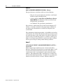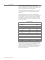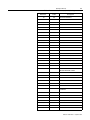
1
Allen-Bradley Reel Tension Paster Adapter (Bulletin 1395) User Manual Important User Information Because of the variety of uses for the products described in this publication, those responsible for the application and use of this control equipment must satisfy themselves that all necessary steps have been taken to assure that each application and use meets all performance and safety requirements, including any applicable laws, regulations, codes and standards. The illustrations, charts, sample programs and layout examples shown in this guide are intended solely for purposes of example. Since there are many variables and requirements associated with any particular installation, Allen-Bradley does not assume responsibility or liability (to include intellectual property liability) for actual use based upon the examples shown in this publication. Allen-Bradley publication SGI-1.1, Safety Guidelines for the Application, Installation and Maintenance of Solid-State Control (available from your local Allen-Bradley office), describes some important differences between solid-state equipment and electromechanical devices that should be taken into consideration when applying products such as those described in this publication. Reproduction of the contents of this copyrighted publication, in whole or part, without written permission of Allen-Bradley Company, Inc., is prohibited. Throughout this manual we use notes to make you aware of safety considerations: ! ATTENTION: Identifies information about practices or circumstances that can lead to personal injury or death, property damage or economic loss. Attention statements help you to: • identify a hazard • avoid a hazard • recognize the consequences Important: Identifies information that is critical for successful application and understanding of the product. DriveTools is a trademark of Rockwell International or its subsidiaries. Table of Contents Preface Who Should Use This Manual . . . . . . . . . . . . . . . . . . . . . . Purpose of This Manual . . . . . . . . . . . . . . . . . . . . . . . . . . . Safety Precautions . . . . . . . . . . . . . . . . . . . . . . . . . . . . . . . Contents of This Manaul. . . . . . . . . . . . . . . . . . . . . . . . . . . Related Documentation . . . . . . . . . . . . . . . . . . . . . . . . . . . Common Techniques Used in This Manual . . . . . . . . . . . . Product Receiving. . . . . . . . . . . . . . . . . . . . . . . . . . . . . . . . Allen-Bradley Support. . . . . . . . . . . . . . . . . . . . . . . . . . . . . P-1 P-1 P-2 P-4 P-4 P-5 P-5 P-5 Chapter 1 Drive Description Drive System . . . . . . . . . . . . . . . . . . . . . . . . . . . . . . . . . . . Controller . . . . . . . . . . . . . . . . . . . . . . . . . . . . . . . . . . . . . . 1-1 1-1 Chapter 2 Description of Operation Drive System . . . . . . . . . . . . . . . . . . . . . . . . . . . . . . . . . . . Drive System Modes . . . . . . . . . . . . . . . . . . . . . . . . . . . . . Global RTP Drive – USA/Europe/Asia-Pacific . . . . . . . . . . 2-1 2-1 2-7 Chapter 3 Start-Up Instructions Introduction . . . . . . . . . . . . . . . . . . . . . . . . . . . . . . . . . . . . Terminology . . . . . . . . . . . . . . . . . . . . . . . . . . . . . . . . . . . . Preliminary Steps . . . . . . . . . . . . . . . . . . . . . . . . . . . . . . . . Start-Up Checklist . . . . . . . . . . . . . . . . . . . . . . . . . . . . . . . Control Boards . . . . . . . . . . . . . . . . . . . . . . . . . . . . . . . . . . Cross Reference . . . . . . . . . . . . . . . . . . . . . . . . . . . . . . . . Speed Match . . . . . . . . . . . . . . . . . . . . . . . . . . . . . . . . . . . Dancer Calibration . . . . . . . . . . . . . . . . . . . . . . . . . . . . . . . 3-1 3-1 3-2 3-3 3-7 3-9 3-16 3-16 Chapter 4 Troubleshooting Introduction . . . . . . . . . . . . . . . . . . . . . . . . . . . . . . . . . . . . Adapter . . . . . . . . . . . . . . . . . . . . . . . . . . . . . . . . . . . . . . . Digital Reference Fault Messages . . . . . . . . . . . . . . . . . . . Multi-Comm Fault Messages . . . . . . . . . . . . . . . . . . . . . . . RIO Faults . . . . . . . . . . . . . . . . . . . . . . . . . . . . . . . . . . . . . DH+ Only Faults . . . . . . . . . . . . . . . . . . . . . . . . . . . . . . . . Press Speed, Magnetic Pickup . . . . . . . . . . . . . . . . . . . . . 4-1 4-2 4-4 4-5 4-5 4-5 4-6 Index Publication 1395-RTP-5.1 - September 1997 Table of Contents This page intentionally left blank. Publication 1395-RTP-5.1 September 1997 Preface Preface Read this preface to familiarize yourself with the rest of the manual. This preface covers the following topics: Who Should Use This Manual • who should use this manual • the purpose of this manual • safety precautions • contents of this manual • related documentation • conventions used in this manual • product receiving • Allen-Bradley support Use this manual if you are responsible for installing an Allen-Bradley 1395 Reel Tension Paster (RTP) Drive. If you do not have a basic understanding of the 1395 Drive, the RTP adapter, or the digital reference adapter for RTP applications, contact your local Allen-Bradley representative for information before using this product. Purpose of This Manual This manual describes the digital reference adapter board functionality for firmware version 4.xx. (The “xx” designator may vary, but it does not affect information in this manual.) Use this manual if you are responsible for installing, wiring, starting up, or troubleshooting RTP control systems. This manual is intended for qualified service personnel responsible for setting up and servicing the 1395 digital DC Drive and RTP accessories. You must have previous experience with and a basic understanding of electrical terminology, programming procedures, required equipment, and safety precautions before attempting to service the 1395 Drive for RTP applications. Publication 1395-RTP-5.1 - September 1997 P-2 Preface Safety Precautions The following general precautions apply to Bulletin 1395 Drives and to RTP applications: ! ATTENTION: Only those familiar with the RTP system, the products used in the system, and the associated machinery should plan or implement the installation, startup, and future maintenance of the system. Failure to comply can result in personal injury and/or equipment damage. ATTENTION: Verify that all sources of AC and DC power are deenergized and locked out or tagged out in accordance with the requirements of ANSI/NFPA 70E, Part II. ATTENTION: Servicing energized industrial control equipment can be hazardous. Severe injury or death can result from electrical shock, burn, or unintended actuation of controlled equipment. Hazardous voltages may exist in the cabinet even with the circuit breaker in the off position. Recommended practice is to disconnect and lock out control equipment from power sources, and discharge stored energy in capacitors, if present. If it is necessary to work in the vicinity of energized equipment, the Safety Related Practices of NFPA 70 E, “ELECTRICAL SAFETY FOR EMPLOYEE WORKPLACES” must be followed. DO NOT work alone on energized equipment! ATTENTION: The system may contain stored energy devices. To avoid the hazard of electrical shock, verify that all voltage on capacitors has been discharged before attempting to service, repair, or remove a Drive system or its components. You should only attempt the procedures in this manual if you are qualified to do so and are familiar with solid-state control equipment and the safety procedures in publication NFPA 70E. ATTENTION: An incorrectly applied or installed Drive can result in component damage and/or a reduction in product life. Wiring or application errors — such as undersizing the motor, incorrect or inadequate AC supply, and excessive ambient temperatures — can result in the malfunction of the Drive equipment. Publication 1395-RTP-5.1 - September 1997 Preface ! P-3 ATTENTION: This Drive system contains ESD (electrostatic discharge) sensitive parts and assemblies. Static control precautions are required when installing, testing, or repairing this assembly. Component damage can result if ESD control procedures are not followed. If you are not familiar with static control procedures, refer to Allen-Bradley publication 8000-4.5.2, Guarding Against Electrostatic Damage or any other applicable ESD protection handbook. ATTENTION: Potentially fatal voltages may result from improper usage of an oscilloscope and other test equipment. The oscilloscope chassis may be at potentially fatal voltage if not properly grounded. If an oscilloscope is used to measure high voltage waveforms, use only a dual channel oscilloscope in the differential mode with X100 probes. It is recommended that the oscilloscope be used in the A minus B Quasi-differential mode with the oscilloscope chassis correctly grounded to an earth ground. Refer to equipment safety instructions for all test equipment before using with the Drive. Publication 1395-RTP-5.1 - September 1997 P-4 Preface Contents of This Manual Chapter Title Contents Preface Purpose, background, and scope of this manual 1 Drive Description Description of equipment and specifications 2 Description of Operation Drive system modes and the global RTP 3 Start-Up Instructions Terminology, parameter set-up and configurations 4 Troubleshooting Digital reference adapter fault messages Related Documentation The following documents contain additional information concerning related Allen-Bradley products and related standards. To obtain a copy of Allen-Bradley publications, contact your local Allen-Bradley office or distributor. For Read This Document Detailed description of the enhanced programming terminal Enhanced Programming Terminal Manual 1300-5.4 Detailed description of the programming terminal Programming Terminal Manual 1300-5.5 Information on the 1395 digital DC Drive 1395 User manual 1395-5.40 Information on troubleshooting the 1395 digital DC Drive 1395 Troubleshooting Manual 1395-5.45 Information on the digital reference adapter for RTP applications Digital Reference Adapter for RTP Applications User Manual 1395-RTP-5.2 A description of Drive Tools™ software Drive Tools Software Brochure 9303-1.0 Information on the Intelligent Terminal System (ITS) Bulletin 1300 Intelligent Terminal System Documentation Set D1300-L00 An article on wire sizes and types for grounding electrical equipment National Electrical Code ANSI / NFPA 70 Published by the National Fire Protection Association of Boston, MA An article on safety procedures Standard for Electrical Safety Requirements for Employee Workplaces ANSI / NFPA 70E A complete listing of current Allen-Bradley documentation, including ordering instructions. Also indicates whether the documents are available on CD-ROM or in multi-languages Allen-Bradley Publication Index SD499 A glossary of industrial automation terms and abbreviations Allen-Bradley Industrial Automation Glossary AG-7.1 Publication 1395-RTP-5.1 - September 1997 Document Number Preface Common Techniques Used in This Manual P-5 The following conventions are used throughout this manual: • Bulleted lists such as this one provide information, not procedural steps. • Numbered lists provide sequential steps or hierarchical information. • When we refer you to another location, the section name appears in italics. • The exclamation point inside of a triangle followed by the word “ATTENTION” indicate circumstances that can lead to personal injury, death, property damage, or economic loss. Product Receiving You, the customer, are responsible for thoroughly inspecting the equipment before accepting the shipment from the freight company. Check the item(s) that you receive against your purchase order. If any items are obviously damaged, it is your responsibility to refuse delivery until the freight agent has noted the damage on the freight bill. Should you discover any concealed damage during unpacking, you are responsible for notifying the freight agent. Leave the shipping container intact and request that the freight agent make a visual inspection of the equipment. Allen-Bradley Support Allen-Bradley offers support services worldwide, with Sales/Support Offices, authorized distributors, and authorized Systems Integrators located throughout the United States, plus representatives in every major country in the world. Local Product Support Contact your local Allen-Bradley representative for: • sales and order support • product technical training • warranty support • support service agreements Technical Product Assistance If you need to contact Allen-Bradley for technical assistance, please review the product and troubleshooting information in this manual first. Then, call your local Allen-Bradley representative. For the quickest possible response, we recommend that you have the catalog numbers of your products available when you call. Publication 1395-RTP-5.1 - September 1997 P-6 Preface This page intentionally left blank. Publication 1395-RTP-5.1 - September 1997 Chapter 1 Drive Description Drive System The Drive System is designed to utilize tension feedback from an Unwind Dancer to regulate paper roll tension, allowing for continuous, non-stop pasting of the new roll to the existing web. Controller The Drive System utilizes a Bulletin 1395 microprocessor based Drive to control the speed and torque of the associated motor. The Drive employs line overcurrent devices to reduce the potential for damage to power semiconductor devices caused by short circuit currents. The Drive also utilizes three microprocessors on the main control board to control the regulator, control logic functions, and control SCR firing and system communication functions. In addition, the digital reference adapter utilizes another microprocessor to provide for a digital-to-digital line speed reference as well as special Dancer potentiometer circuitry and on-board drive state machines for outer loop control of the Drive. Extensive diagnostics are built into the Drive to aid in troubleshooting, thus, correcting many Drive and related system problems. The Drive resolves all internal faults to guard against needless Drive trips during normal operation. To better understand the associated Drive, refer to the appropriate Bulletin 1395 Instruction Manual to obtain in-depth knowledge of the Drive functions. Publication 1395-RTP-5.1 - September 1997 2 Drive Description This page intentionally left blank. Publication 1395-RTP-5.1 - September 1997 Chapter 2 Description of Operation Drive System The RTP Drive utilizes a three phase, armature regeneration, digital DC Bulletin 1395 Drive to control the DC motor in a surface driven unwind. The speed demand for the Unwind Drive is generated from press speed via a zero speed magnetic pickup. In normal operation, the press speed reference is trimmed by dancer position error to maintain constant dancer position. The Drive allows for speed matching, automatic slack take-up, paying off to full dancer storage, regenerative stopping under current limit control and regenerative stopping with controlled deceleration. Drive System Modes The Drive operation modes are grouped as follows. Refer to Logic State Diagrams in the System Binder as required. Mode Description 0 to 14 Drive logic 20 to 3l Drive reference control The status of each input and output signal to the Drive Digital Reference Adapter Board is tabulated at the end of this section. This table may be used to diagnose the status of the system if a fault is suspected. LED indicators are employed on the Adapter Board to assist in identifying which inputs and outputs are ON at any given time. Mode 0 DRIVE READY When the Drive is at standstill with the contactor open in a ready condition, it will be in Mode zero. In this Mode, the Drive is waiting for any type of run command. Mode 1 NORMAL RUN (Motor controller follows press speed trimmed by dancer position) A “Drive Permit” signal is received which starts the Drive. A pulsed “Emulate” signal is also received, approximately 2 seconds in length, which allows the Drive to pull the dancer into position without detecting a web out. Publication 1395-RTP-5.1 - September 1997 2-2 Description of Operation The press speed is measured with a magnetic pickup and fed into the Digital Reference Adapter Board on the Drive. This signal serves as the basic speed reference for the unwind belts. The press speed signal is linked to the Drive Velocity Reference (Parameters 153 and 154) and sent through the Drive Ramp Control. The dancer input is fed into the analog input channel on the Drive and linked to the Process Trim Reference (Parameter 161) and sent through the Process Trim Control. The output of the ramp control is summed with the output of the process trim to obtain the final velocity reference. The position of the dancer is continuously monitored, in all Normal Run Modes, so that if a web break occurs, the motor controller will regenerate to zero speed under current limit control. The Drive Permit input will remain present for 15 seconds after zero speed is reached, keeping the Main Contactor closed. At the end of 15 seconds, the Drive Permit input drops out causing the Main Contactor to open and the Drive will turn off. (See Mode 10.) Mode 2 PASTE CYCLE (Motor controller follows press speed with no dancer trim) When the “Tension Remove” input is received, the belts are removed from the expiring roll and the dancer trim is turned OFF; hence, the motor controller follows press speed only. At this point, the Goss core brake has control of the expiring roll. Mode 3 DECEL CYCLE (Decelerate under ramp control: 2 seconds after initiating a paste.) After 2 seconds, determined by Parameter 580, after receiving the “Tension Remove” signal, the press speed reference is removed and the Drive velocity reference is set to zero (preset speed 3 with a value of zero RPM). This will ramp the Drive down to zero speed with the main contactor remaining energized and the Drive active. The ramp rate is set by Drive Parameter 652. At this point, the turret indexes and a new roll of paper is positioned under the raised belts. When the new roll is in position, the belts may be lowered. Mode 4 ACCEL CYCLE (The belts accelerate a new roll of paper to speed match with the press.) When the “Accel” signal is received, the press speed reference is once again used as the velocity reference for the Drive. The belts ramp up to the press speed. The accel rate is set by Drive Parameter 651. Publication 1395-RTP-5.1 - September 1997 Description of Operation 2-3 When the belts have accelerated to line speed, the up-to-speed algorithm in the Drive energizes the “Speed Match” output. The belts should be fully down on the new roll before the accelerate mode is initiated. When the “Speed Match” signal is present the new roll is ready to splice. Mode 5 SPEED MATCH (The new roll is spliced in and the belt Drive system returns to Mode 1.) When the new roll has been accelerated to speed match with the press and the new web has been pasted onto the web from the old roll, the knife will fire to cut off the old roll. At the same time the knife fires, the “Tension Reset” signal is sent momentarily. This resets the tension remove timer and resets the Drive to Mode 1. When the “Tension Reset” signal is received, dancer control will return to the belts and the Goss core brake will be disabled. To enter Mode 5, the “At Speed” signal must be ON and the motor CANNOT be at Zero Speed. Mode 6 NORMAL STOP When the “Decel” input is received in Modes 4 or 5, the belt Drive system is stopped by ramping to zero speed and opens the main contactor. At zero speed, the operator initiated “Tension Reset” signal is received, returning the Drive to Mode zero, Drive ready. Mode 7 AUTO SLACK, WEB TIGHT The Auto Slack Mode is designed so that the belts will slowly pay off web whenever the dancer is tensioned. In the Auto Slack Mode as in the Normal Run Mode, the web out detector compares the dancer position with an acceptable dancer range. The Drive is allowed to enter Mode 7 when the dancer is below the dancer mid-position level, which is halfway between the dancer center and dancer full positions. When the “Auto Slack” signal is received, the Drive automatically starts in Mode 7 and runs at a preset speed (adjustable with Drive Parameter 633) which is set above the press thread (inch) speed. Thus during Mode 7, the reel is paying-out paper. The belts will run from this internal speed reference with no dancer trim. The normal exit from Mode 7 is to Mode 8 when the Dancer reaches full position. If the Drive receives a “Drive Permit” signal (DI2), the Drive reverts to Mode 1 (Normal Run). Publication 1395-RTP-5.1 - September 1997 2-4 Description of Operation Mode 8 AUTO SLACK, WEB LOOSE With the “Auto Slack” signal present, the web out detector is de-energized when the dancer reaches full position and the web becomes fully slack. This sets the torque reference to zero which will allow the motor to free-wheel, (no armature current or torque) but keeps the Drive energized. The normal exit from Mode 8 is back to Mode 7 via the Dancer reaching mid-position unless both inputs DI2 and DI7 are low, in which case, Mode 8 exits to Mode 11. Mode 9 REVERSE RUN, DANCER HIGH The Reverse Run Mode is designed so the belts will slowly run in reverse to pull the dancer to the center position. In the Reverse Run Mode, a “Slack Removal” signal is received by the Drive. This sets the Drive logic command to start the Drive and follow the internal preset 2 speed reference. This signal is adjustable with Drive Parameter 634 and requires a negative number for reverse operation. When the web out detector senses the web out of position on the slack side of center, the belts will reverse slowly. The Drive logic command ensures that the Drive will run from the preset 2 speed reference with no dancer trim. Mode 10 WEB OUT If the web breaks when the Drive is in any Normal Run Mode (Modes 1 through 5), the Drive goes into a regenerative stop. Configuration Parameter 572, Bit 2 will determine if Drive will go into a full regen stop or a ramped regen stop. Refer to Logic State Diagrams. When the Drive senses that the dancer has gone fully slack (dancer full up), the Drive loses its run command. The main contactor will remain energized until the Drive senses zero speed. ! Publication 1395-RTP-5.1 - September 1997 ATTENTION: If the “Drive Permit” signal is high, the Drive will start as soon as dancer is pulled down below web-out position. Description of Operation 2-5 Mode 11 REGENERATIVE STOP This mode is entered if Drive Permit drops out during any of the Modes 1 to 5. This mode is also entered when exiting Mode 8 (Auto Slack,Web Loose), Mode 9 (Reverse Run, Dancer High) and Mode 14 (Reverse Run, Dancer Center). This stops the roll by sending the controller into a regenerative stop. Configuration Parameter 572, Bit 2 will determine if Drive will go into a full regen stop or a ramped regen stop. Refer to Logic State Diagrams. Mode 12 INTERNAL DRIVE FAULT If the Drive detects an internal fault, the main contactor will open and set the belt emergency brake. The Drive will latch in a faulted state and must be stopped, reset, and restarted once the fault has been corrected. For detailed troubleshooting information, refer to the Bulletin 1395 Installation and Maintenance Manual. Mode 13 DRIVE NOT READY Any time the Drive ready bit, Bit 7, in the logic status word (Parameter 100) goes low, the Drive will go to Mode 13. Refer to the Bulletin 1395 Installation and Maintenance Manual for more information on logic status. The Drive will not exit Mode 13 until Bit 7 goes high and inputs 2, 7 and 8 are all low. Mode 14 RUN REVERSE DANCER CENTER This mode is entered from Mode 9, Run Reverse Dancer High, when slack is removed, pulling dancer to center position. If dancer moves above center position, Drive enters Mode 9, and returns to Mode 14 when dancer reaches center position. The normal exit out of Mode 14 is back to Mode 9 which occurs when the dancer moves above center position, but if a Drive permit (DI2) is received the Drive goes directly into Mode 1 Normal Run. Mode 20 SPEED REFERENCE RESET The Drive does not have a speed reference in this mode. It has not gone into a normal run, auto slack, or slack remove mode. Publication 1395-RTP-5.1 - September 1997 2-6 Description of Operation Mode 21 LINE SPEED REFERENCE When the Drive is in a normal run (Mode 1) or accel cycle (Mode 4), the Drive will follow the press speed reference. Mode 22 PRESET 1 SPEED REFERENCE When the Drive is in auto slack with the web tight (Mode 7), the Drive will follow the Preset 1 speed reference. This is a low forward speed reference which is adjustable in Drive Parameter 633. Mode 23 PRESET 2 SPEED REFERENCE When the Drive is in run reverse, dancer high (Mode 9), the Drive will follow the Preset 2 speed reference. This is a low reverse speed reference which is adjustable in Drive Parameter 634. Mode 24 TORQUE SELECT The torque select Parameter in the Drive (Parameter 625) is normally set so the Drive is a velocity regulator. When running in auto slack with the dancer in the full up position, the torque select Parameter is set to zero which is zero torque command. This prevents any motor armature current and torque while keeping the Drive energized with the main contactor picked up. This will prolong contactor life by eliminating the cycling ON and OFF of the contactor during web up. Mode 25 TORQUE SELECT TORQUE REFERENCE REVERSE This mode is used for reverse run only. When in logic Mode 9, the Drive will run slowly in reverse at preset 2 speed reference until dancer is centered, then reference will change to torque mode with zero torque command. This prevents motor armature current and torque while keeping the Drive energized with the main contactor picked up. Mode 26 PROCESS TRIM DISABLE Any time the Drive is in the paste cycle, the dancer trim is disabled. This allows the Drive to run from the velocity reference only. The velocity reference could be zero or press speed reference. Publication 1395-RTP-5.1 - September 1997 Description of Operation 2-7 Mode 27 PROCESS TRIM ENABLE This enables the process trim in the Drive to allow proper tensioning of the web. Movement of the dancer will either add or subtract from the press speed reference in order to hold the dancer close to the center position at all times during normal run. Global RTP Drive – USA / Europe / Asia-Pacific Two new drive reference control modes have been added to allow for adjustable Auto-Slack Speed Control (Asia-Pacific), or for adjustable Emulate Speed Reference Control (Europe). Either of these customer inputs will enter the Drive at analog input number 2 of the Digital Reference Adapter (DRA) board of the Bulletin 1395 Drive. Parameter 572 is a configuration Parameter that is to be used to determine if analog input number 2 will be used for either adjustable Emulate Speed Reference (ESR), or adjustable Auto-Slack Reference, defined as Auto-Slack Tight Variable Reference (ASTVR). Digital input number 9 of the DRA board must also be held high to access mode 30, ESR. Parameter 572 The Parameter 572 configuration truth table follows. Refer to the Logic State Diagrams in Chapter 6 of this manual. Bit 2 Bit 1 Bit 0 0 0 0 = USA 0 0 1 = Europe – ESR Mode 30 0 1 0 = Asia-Pacific – ASTVR Mode 31 Note: Parameter 572 Bit 2 is set to a value of one for CT50P design. Without making any link changes to the Drive, these two new modes of operation can be accessed by the proper configuration of Parameter 572 and the customer supplied inputs to analog input number 2 of the Digital Reference Adapter board. Following are the descriptions of the two additional reference control modes. Publication 1395-RTP-5.1 - September 1997 2-8 Description of Operation Mode 30 EMULATE SPEED REFERENCE (ESR) – Europe The speed reference to the Drive will be one of the following: • The press line speed, which enters the Drive at the Digital Reference input of the DRA board. • A preset speed for Auto-Slack and Run Reverse Dancer High (RRDH) (Slack Remove). Refer to the State Logic Diagram in the system binder. • An “Emulated” line speed from a potentiometer. Drive reference control mode 30 can be observed in Parameter 597 which is a “read only” Parameter if the proper input conditions are met. Refer to the Drive Reference Control State Diagram in the system binder. The combination of digital input number 9 of the DRA board and bit 0 of Parameter 572 set high will determine which speed reference will be used by the Drive to enter either mode 21 or mode 30. Mode 30 is used for testing and calibrating purposes, to simulate a running press. Mode 21 is the normal speed reference mode for the Drive to follow the line speed of the press during normal running conditions. Mode 31 AUTO-SLACK TIGHT VARIABLE REFERENCE (ASTVR) – Asia-Pacific With the proper input conditions present as shown on the Drive Reference Control State Diagram in the system binder, Mode 31 will be entered and allow the Auto-Slack speed to be adjustable by an external means such as a potentiometer connected to analog input number 2. The combination of Bit 1 of Parameter 572 set high, and the Auto-Slack digital input number 7 set high will access this mode, which can be observed in the “read only” Parameter (ROP) 597. Publication 1395-RTP-5.1 - September 1997 Chapter 3 Start-Up Instructions Introduction The following start-up instructions should be used to fine tune the operation of the RTP Drive. The complete start-up procedure for the associated Drive can be found in the Bulletin 1395 Installation and Maintenance Manual. Read and understand the complete procedure prior to attempting start-up of the RTP Drive. Important: Before attempting to operate the Drive, ensure that the mechanics of the associated press system have been checked and properly set up. Check the: • gearbox fluid level • type of lubricant used • belt tension • associated wiring • mag pick-up gap per Goss specifications Pre-Power Drive Checks – 1. Power Terminations within the Drive are tight 2. All control wiring is secure 3. All wiring and cabinets are properly grounded 4. All control boards are secure 5. All terminal blocks are secure Terminology Parameter Memory location used to store Drive set-up data, or to monitor real time input or output information. Each parameter is assigned a name and number which does not change. Set-Up Parameter Parameter whose values do not change during normal operation of the Drive. The Set-Up Parameters are used for scaling and calibration of specific Drive functions which are application and/or hardware dependent. Read-Only Parameter Parameter whose value cannot be changed by any external device. Special Parameter used only for the purpose of monitoring several internal strategic variables. Publication 1395-RTP-5.1 - September 1997 3-2 Start-Up Instructions Configuration Parameter Parameter whose value may be changed during normal operation of the Drive. The Configuration Parameters are used to input reference and feedback information to the Drive, and to provide monitoring points for control signals. The Configuration Parameters are one of two types, termed Source or Sink Parameters. Refer to the Bulletin 1395 Installation and Maintenance manual for detailed description of Source and Sink Parameters. Source Parameter which may be used as a source of data for output to a sink. Sink Parameter which acts as an input of data from a source. Linking The process of connecting a Sink Parameter to a Source Parameter. Preliminary Steps These steps should already have been accomplished in a Custom Drive Manufactured and Shipped as an RTP Unwind Drive. 1. If a Drive that has already been installed is receiving a Digital Adapter Board as an added feature then all of the necessary configuration links, etc. will have to be made. 2. If a given Drive for any reason loses the EE memory information, it will also be necessary to go through the necessary software steps in order to perform the links and set defaults of the setup Parameters. These steps will vary from one installation to the next dependent upon the capability of the support equipment available. 3. Should there be a need to check or download Parameters to the Drive, use of the ITS device will prove to be one of the most efficient methods. ITS (Monitor) To monitor Parameters: – From Main Menu, Select Diagnostics, ENTER key, Select “Monitor”, ENTER key, Select “Table”, ENTER key Publication 1395-RTP-5.1 - September 1997 Start-Up Instructions 3-3 ITS (Download) To download from ITS to Drive: From Main Menu, Select “Drive Data”, Select “Edit” ENTER key, Select “Parameter”, (cursor through Parameters), make changes, ESC, Select “EEPROM”, ENTER key, Select “Save”, ENTER key DHT (Hand-Held Programming Terminal) From Main Menu, Select “Parameters”, Type Parameter number, ENTER key, Arrow-down cursor to value and type new value, ENTER key, When changes are completed, depress “MENU” key, The DHT will prompt “SAVE CHANGES”? Select “Yes”, ENTER key Start-Up Checklist Verify J6 and J7 jumpers on the Digital Reference Adapter Board are in Position 1-2. Verify J1 jumper on Feedback section of the PSI/Switcher Board of the 1395 Drive is in Position 3. Verify J8, J9, and J10 jumpers on the Main Control Board of the 1395 Drive to be in Position 1-2 (Figure 3-1). Verify burden resistors on Feedback Board to be 25.2 Ohms on TB1 and 80 Ohms on TB3, for a 1395-B68, or, 13.8 Ohms on TB1 and 45.9 Ohms on TB3 for a 1395-B70. Verify incoming AC line to Drive, L1, L2, and L3, to 380 or 460 VAC, ± 10%. Publication 1395-RTP-5.1 - September 1997 3-4 Start-Up Instructions Connect hand held programming terminal to Drive at DHT Connector, located to the left of TB3 at the bottom of the Drive. Upon power-up, communications are initialized as indicated by the letter I in Drive graphically displaying a moving pendulum. Check LEDs on Digital Reference Adapter Board for +12V, -12V, +5V, and +24V Status. (See Troubleshooting section for further explanation.) Verify links and parameters match the tables provided using the Programmable Terminal. To access links, enter “Drive Set Up” mode, select “Read Edit”, and view the next link each time the “ENTER” key is depressed. If necessary, parameters and links can be entered with the DHT or the Intelligent Terminal System, (ITS), if available or Drive Tools software. Table 1: Link List Parameter Links Sink Source 450 TO 100 151 TO 400 152 TO 200 153 TO 404 154 TO 403 161 TO 407 163 TO 405 164 TO 408 165 TO 410 166 TO 411 250 TO 100 The following Parameter list is a quick reference table showing the set-up parameters and values associated with an RTP start-up. (The motor data is for G.E. and Baldor Motors, refer to proper – 18 drawings for other motors). Refer to Bulletin 1395 Drive Installation & Maintenance Manual or associated schematics for complete Parameter list and descriptions. Publication 1395-RTP-5.1 - September 1997 Start-Up Instructions 3-5 Table 2: Parameter List, Factory (Initial) Settings Parameter * Value Description 551 0.0 ANALOG OFFSET #1 553 0.0 DIGITAL OFFSET #1 * 558 1500 DANCER FULL POSITION * 559 750 DANCER MID-POSITON * 561 131 PRESS REF PPR * 562 2566 MAX PRESS REF RPM 563 400 VELOCITY KI LOW 564 1700 VELOCITY KI HIGH 565 150 VELOCITY KP LOW 566 425 VELOCITY KP HIGH 567 50 PROCESS REG KI * 569 30 VP KI/KP SWITCH RPM * 570 -20 LOW SUM RRDH 571 0 600 625 VEL INDIRECT 1 (P.163) 601 721 VEL INDIRECT 2 (P.164) 602 659 VEL INDIRECT 3 (P.165) 603 660 VEL INDIRECT 4 (P.166) 606 1750 BASE MOTOR SPEED * 607 -20 * 608 1560 FORWARD SPEED LIMIT BELT MOTOR RPM PER CHART 609 210 ENCODER PPR 610 500 RATED MOTOR VOLTAGE 611 20.6 MOTOR ARMATURE FLA 612 1.2 RATED FIELD MOTOR CURRENT 613 6 614 5.78 615 40 RATED ARMATURE BRIDGE CURRENT 616 2.1 RATED FIELD BRIDGE CURRENT 617 460 RATED AC LINE VOLTAGE 621 0 FEEDBACK DEVICE TYPE 628 1 PROCESS TRIM SELECT * 633 20 PRESET SPEED 1 * 634 -20 PRESET SPEED 2 635 0 PRESET SPEED 3 LOW SUM NORMAL REVERSE SPEED LIMIT MOTOR INERTIA ARMATURE RESISTANCE Publication 1395-RTP-5.1 - September 1997 3-6 Start-Up Instructions Table 2: Parameter List, Factory (Initial) Settings (Continued) Parameter Value Description 651 20 ACCEL TIME 652 10 DECEL TIME 659 400 KI VELOCITY LOOP 660 150 KP VELOCITY LOOP 661 65535 KF VELOCITY LOOP 663 150 FORWARD BRIDGE CURRENT LIMIT 664 150 REVERSE BRIDGE CURRENT LIMIT 713 0 PROCESS TRIM FILTER 714 0 INTEGRAL PRELOAD 715 0 KI INTEGRAL GAIN 716 4096 KP PROPORTIONAL GAIN 717 -165 PROCESS TRIM LOW LIMIT 718 165 PROCESS TRIM HIGH LIMIT 719 -1 720 150 721 0 PROCESS TRIM LOW SUM 722 1750 PROCESS TRIM HIGH SUM 724 75 ABSOLUTE OVERSPEED 725 10 EXTERNAL OVERTEMP DELAY 726 10 SCR OVERTEMP DELAY 727 2 STALL DELAY 728 1 AC LINE TOLERANCE DELAY 730 1 FIELD FAILURE DELAY 731 15 TACH LOSS CEMF 732 0.5 TACH LOSS VELOCITY 733 1 734 155 K DISCONTINOUS 735 1659 KP ARMATURE LOOP 736 136 KI ARMATURE LOOP 737 16384 KP FIELD LOOP 738 512 KI FIELD LOOP * 739 12350 K ARM VOLTS * 740 7200 K AC VOLTS P/I REGULATOR OUTPUT GAIN OVERLOAD PENDING LEVEL ARM BRIDGE TYPE * DEFAULTS may be adjusted per installation as required. Publication 1395-RTP-5.1 - September 1997 Start-Up Instructions Control Boards 3-7 Main Control Board (A8) – Figure 3-1 illustrates the major hardware points on the board. The board performs all control functions of the Bulletin 1395 Drive. Hardware located on the board is used to support operation of the microprocessor program. The primary functions performed include: • Microbus Interface • Control Firmware • Analog Signal Interface • Develop gate control signals sent to the Power Stage Interface Publication 1395-RTP-5.1 - September 1997 3-8 Start-Up Instructions Figure 3.1 Main Control Board Overview Publication 1395-RTP-5.1 - September 1997 Start-Up Instructions Cross Reference 3-9 The printing diameter Tables 3 through 6 provide the proper tracking information such as the number of gear teeth for the magnetic pickup gear, the maximum belt motor speed and the press shaft speed at maximum press impressions per hour. The main tracking Parameter (Parameter 562) should be set at the maximum press shaft speed that corresponds to the maximum press impressions per hour. The value used for default is 2566. Table 3: Cross Reference (Printing Diameter = 14-1/32; Gear Teeth = 131) IMP/ HOUR RTP PRESS SPD. SENSOR FREQ (HZ) WEB VELOCITY (FT/MIN) BELT MOTOR RPM PRESS DRIVE SHAFT RPM 100 7.28 3.06 2.08 3.33 400 29.11 12.24 8.32 13.33 600 43.67 18.37 12.48 20.00 800 58.22 24.49 16.64 26.67 1000 72.78 30.61 20.80 33.33 1200 87.33 36.73 24.96 40.00 2000 145.56 61.22 41.60 66.67 4000 291.11 122.45 83.20 133.33 6000 436.67 183.67 124.80 200.00 8000 582.22 244.89 166.40 266.67 10000 727.78 306.11 208.00 333.33 12000 873.33 367.34 249.60 400.00 14000 1018.89 428.56 291.20 466.67 16000 1164.44 489.78 322.80 533.33 18000 1310.00 551.00 374.40 600.00 20000 1455.55 612.23 416.00 666.67 22000 1601.11 673.45 457.60 733.33 24000 1746.66 734.67 499.20 800.00 26000 1892.22 795.89 540.80 866.67 28000 2037.78 857.12 582.40 933.33 30000 2183.33 918.34 624.00 1000.00 32000 2328.89 979.56 665.60 1066.67 34000 2474.44 1040.78 707.20 1133.33 36000 2620.00 1102.01 748.80 1200.00 38000 2765.55 1163.23 790.39 1266.67 Publication 1395-RTP-5.1 - September 1997 3-10 Start-Up Instructions Table 3: Cross Reference (Printing Diameter = 14-1/32; Gear Teeth = 131) (Continued) Publication 1395-RTP-5.1 - September 1997 IMP/ HOUR RTP PRESS SPD. SENSOR FREQ (HZ) 40000 2911.11 42000 WEB VELOCITY (FT/MIN) BELT MOTOR RPM PRESS DRIVE SHAFT RPM 1224.45 831.99 1333.33 3056.66 1285.67 873.59 1400.00 44000 3202.22 1346.90 915.19 1466.67 46000 3347.77 1408.12 956.79 1533.33 48000 3493.33 1469.34 998.39 1600.00 50000 3638.89 1530.56 1039.99 1666.67 52000 3784.44 1591.79 1081.59 1733.33 54000 3930.00 1653.01 1123.19 1800.00 56000 4075.55 1714.23 1164.79 1866.66 58000 4221.11 1775.45 1206.39 1933.33 60000 4366.66 1836.68 1247.99 2000.00 62000 4512.22 1897.90 1289.59 2066.66 64000 4657.77 1959.12 1331.19 2133.33 66000 4803.33 2020.34 1372.79 2200.00 68000 4948.88 2081.57 1414.39 2266.66 70000 5094.44 2142.79 1455.99 2333.33 72000 5239.99 2204.01 1497.59 2400.00 74000 5385.55 2265.23 1539.19 2466.66 75000 5458.33 2295.85 1559.99 2500.00 76000 5531.11 2326.46 1580.79 2533.33 78000 5676.66 2387.68 1622.39 2600.00 80000 5822.22 2448.90 1663.99 2666.66 Start-Up Instructions 3-11 Table 4: Cross Reference (Printing Diameter = 14-1/2; Gear Teeth = 135) IMP/ HOUR RTP PRESS SPD. SENSOR FREQ (HZ) WEB VELOCITY (FT/MIN) BELT MOTOR RPM PRESS DRIVE SHAFT RPM 100 7.50 3.16 2.14 3.33 400 30.00 12.65 8.57 13.33 600 45.00 18.98 12.86 20.00 800 60.00 25.31 17.15 26.67 1000 75.00 31.63 21.43 33.33 1200 90.00 37.96 25.72 40.00 2000 150.00 63.27 42.87 66.67 4000 300.00 126.54 85.74 133.33 6000 450.00 189.80 128.61 200.00 8000 600.00 253.07 171.48 266.67 10000 750.00 316.34 214.35 333.33 12000 900.00 379.61 257.22 400.00 14000 1050.00 442.87 300.09 466.67 16000 1200.00 506.14 342.96 533.33 18000 1350.00 569.41 385.83 600.00 20000 1500.00 632.68 428.70 666.67 22000 1650.00 695.95 471.57 733.33 24000 1800.00 759.21 514.44 800.00 26000 1950.00 822.48 557.31 866.67 28000 2100.00 885.75 600.18 933.33 30000 2250.00 949.02 643.05 1000.00 32000 2400.00 1012.29 685.92 1066.67 34000 2550.00 1075.55 728.79 1133.33 38000 2850.00 1202.09 814.53 1266.67 40000 3000.00 1265.36 857.40 1333.33 42000 3150.00 1328.62 900.27 1400.00 44000 3300.00 1391.89 943.14 1466.67 46000 3450.00 1455.16 986.01 1533.33 48000 3600.00 1518.43 1028.88 1600.00 Publication 1395-RTP-5.1 - September 1997 3-12 Start-Up Instructions Table 4: Cross Reference (Printing Diameter = 14-1/2; Gear Teeth = 135) (Continued) IMP/ HOUR RTP PRESS SPD. SENSOR FREQ (HZ) WEB VELOCITY (FT/MIN) BELT MOTOR RPM PRESS DRIVE SHAFT RPM 50000 3750.00 1581.70 1071.75 1666.67 52000 3900.00 1644.96 1114.62 1733.33 54000 4050.00 1708.23 1157.49 1800.00 56000 4200.00 1771.50 1200.36 1866.66 58000 4350.00 1834.77 1243.23 1933.33 60000 4500.00 1898.04 1286.10 2000.00 62000 4650.00 1961.30 1328.97 2066.66 64000 4800.00 2024.57 1371.84 2133.33 66000 4950.00 2087.84 1414.71 2200.00 68000 5100.00 2151.11 1457.58 2266.66 70000 5250.00 2214.37 1500.45 2333.33 72000 5400.00 2277.64 1543.32 2400.00 74000 5550.00 2340.91 1586.19 2466.66 75000 5625.00 2372.54 1607.62 2500.00 76000 5700.00 2404.18 1629.06 2533.33 78000 5850.00 2467.45 1671.93 2600.00 80000 6000.00 2530.71 1714.80 2666.66 Table 5: Cross Reference (Printing Diameter = 13-11/16; Gear Teeth = 128) IMP/ HOUR Publication 1395-RTP-5.1 - September 1997 RTP PRESS SPD. SENSOR FREQ (HZ) WEB VELOCITY (FT/MIN) BELT MOTOR RPM PRESS DRIVE SHAFT RPM 100 7.11 2.99 2.03 3.33 400 28.44 11.94 8.13 13.33 600 42.67 17.92 12.19 20.00 800 56.89 23.89 16.26 26.67 1000 71.11 29.86 20.32 33.33 1200 85.33 35.83 24.39 40.00 2000 142.22 59.72 40.65 66.67 4000 284.44 119.45 81.29 133.33 Start-Up Instructions 3-13 Table 5: Cross Reference (Printing Diameter = 13-11/16; Gear Teeth = 128) (Continued) RTP PRESS SPD. SENSOR FREQ (HZ) WEB VELOCITY (FT/MIN) BELT MOTOR RPM 6000 426.67 179.17 121.94 200.00 8000 568.89 238.89 162.59 266.67 10000 711.11 298.61 203.24 333.33 12000 853.33 358.34 243.88 400.00 14000 995.55 418.06 284.53 466.67 16000 1137.78 477.78 325.18 533.33 18000 1280.00 537.50 365.82 600.00 20000 1422.22 597.23 406.47 666.67 22000 1564.44 656.95 447.12 733.33 24000 1706.66 716.67 487.76 800.00 26000 1848.89 776.39 528.41 866.67 28000 1991.11 836.12 569.06 933.33 30000 2133.33 895.84 609.71 1000.00 32000 2275.55 955.56 650.35 1066.67 34000 2417.78 1015.29 691.00 1133.33 36000 2560.00 1075.01 731.65 1200.00 38000 2702.22 1134.73 772.29 1266.67 40000 2844.44 1194.45 812.94 1333.33 42000 2986.66 1254.18 853.59 1400.00 44000 3128.89 1313.90 894.24 1466.67 46000 3271.11 1373.62 934.88 1533.33 48000 3413.33 1433.34 975.53 1600.00 50000 3555.55 1493.07 1016.18 1666.67 52000 3697.77 1552.79 1056.82 1733.33 54000 3840.00 1612.51 1097.47 1800.00 56000 3982.22 1672.23 1138.12 1866.66 58000 4124.44 1731.96 1178.77 1933.33 IMP/ HOUR PRESS DRIVE SHAFT RPM Publication 1395-RTP-5.1 - September 1997 3-14 Start-Up Instructions Table 5: Cross Reference (Printing Diameter = 13-11/16; Gear Teeth = 128) (Continued) IMP/ HOUR RTP PRESS SPD. SENSOR FREQ (HZ) WEB VELOCITY (FT/MIN) BELT MOTOR RPM PRESS DRIVE SHAFT RPM 60000 4266.66 1791.68 1219.41 2000.00 62000 4408.88 1851.40 1260.06 2066.66 64000 4551.11 1911.13 1300.71 2133.33 66000 4693.33 1970.85 1341.35 2200.00 68000 4835.55 2030.57 1382.00 2266.66 70000 4977.77 2090.29 1422.65 2333.33 72000 5119.99 2150.02 1463.29 2400.00 74000 5262.22 2209.74 1503.94 2466.66 75000 5333.33 2239.60 1524.27 2500.00 76000 5404.44 2269.46 1544.59 2533.33 78000 5546.66 2329.18 1585.24 2600.00 80000 5688.88 2388.91 1625.88 2666.66 Table 6: Cross Reference (Printing Diameter = 15; Gear Teeth = 140) IMP/ HOUR Publication 1395-RTP-5.1 - September 1997 RTP PRESS SPD. SENSOR FREQ (HZ) WEB VELOCITY (FT/MIN) BELT MOTOR RPM PRESS DRIVE SHAFT RPM 100 7.78 3.27 2.22 3.33 400 31.11 13.09 8.89 13.33 600 46.67 19.63 13.34 20.00 800 62.22 26.18 17.78 26.67 1000 77.78 32.72 22.23 33.33 1200 93.33 39.27 26.67 40.00 2000 155.56 65.45 44.46 66.67 4000 311.11 130.90 88.92 133.33 6000 466.67 196.35 133.37 200.00 8000 622.22 261.80 177.83 266.67 10000 777.78 327.25 222.29 333.33 12000 933.33 392.70 266.75 400.00 14000 1088.89 458.15 311.20 466.67 16000 1244.44 523.60 355.66 533.33 18000 1400.00 589.05 400.12 600.00 Start-Up Instructions 3-15 Table 6: Cross Reference (Printing Diameter = 15; Gear Teeth = 140) (Continued) IMP/ HOUR RTP PRESS SPD. SENSOR FREQ (HZ) WEB VELOCITY (FT/MIN) BELT MOTOR RPM 20000 555.56 654.50 444.58 666.67 22000 1711.11 719.94 489.04 733.33 24000 1866.67 785.39 533 49 800.00 26000 2022.22 850.84 577.95 866.67 28000 2177.78 916.29 622.41 933.33 30000 2333.33 981.74 666.87 1000.00 32000 2488.89 1047.19 711.32 1066.67 34000 2644.44 1112.64 755.78 1133.33 36000 2800.00 1178.09 800.24 1200.00 38000 2955.56 1243.54 844.70 1266.67 40000 3111.11 1308.99 889.16 1333.33 42000 3266.67 1374.44 933.61 1400.00 44000 3422.22 1439.89 978.07 1466.67 46000 3577.78 1505.34 1022.53 1533.33 48000 3733.33 1570.79 1066.99 1600.00 50000 3888.89 1636.24 1111.44 1666.67 52000 4044.44 1701.69 1155.90 1733.33 54000 4200.00 1767.14 1200.36 1800.00 56000 4355.56 1832.59 1244.82 1866.66 58000 4511.11 1898.04 1289.28 1933.33 60000 4666.67 1963.49 1333.73 2000.00 62000 4822.22 2028.93 1378.19 2066.66 64000 4977.78 2094.38 1422.65 2133.33 66000 5133.33 2159.83 1467.11 2200.00 68000 5288.89 2225.28 1511.56 2266.66 70000 5444.44 2290.73 1556.02 2333.33 72000 5600.00 2356.18 1600.48 2400.00 74000 5755.55 2421.63 1644.94 2466.66 75000 5833.33 2454.36 1667.17 2500.00 76000 5911.11 2487.08 1689.40 2533.33 78000 6066.67 2552.53 1733.85 2600.00 80000 6222.22 2617.98 1778.31 2666.66 PRESS DRIVE SHAFT RPM Publication 1395-RTP-5.1 - September 1997 3-16 Start-Up Instructions Speed Match The Drive is set up at the factory to ensure an accurate speed match between the new roll coming up to speed and the existing web. This is accomplished by using the at set speed algorithm in the Drive. The up to speed tolerance (Parameter 709) sets the hysteresis in motor RPM around the at speed point. When the new roll is speed matched with the press speed reference, and the motor is not at zero speed, the Drive will go into Mode 5 which is speed match. This turns on digital output #1 to produce an external indication to the paster panel. Dancer Calibration Drive Not Started Dancer Voltage – The dancer potentiometer voltage should always be plus when the dancer is in the up or “WEB OUT” position. Determine whether the specific application is right hand or left hand as observed from the GSD console looking at the reel. Check to assure that the Drive wiring conforms to applicable configuration. Dancer at Center Position – The dancer at center position or at a horizontal level position is a mechanical benchmark which will continue to be used throughout the life of the press. One way of quickly and reputably setting the dancer at center position is to establish a mechanical data point for the placement of a machined block that acts as a setup block to restrict the dancer of downward movement only during setup and troubleshooting with no paper webbed from the reel. Two of these machined blocks are recommended, one for each side of the dancer. Once the dancer potentiometer has been set up for 0.0 volts DC, ± 0.2 volts, with the dancer in the horizontal level position, the following normal adjustments to the setup parameters can be made prior to starting the Drive. Preliminary Steps: A. Disable the process trim system by setting Parameter 628 to zero. B. Disable the integral channel of the P/I Regulator by setting Parameter 567 to zero. 1. Using a digital voltmeter, monitor test point TP14 to TP12 on the Digital Reference Adapter Board. The voltage should be 0.0 volts DC with the dancer in the horizontal or dancer center position. If there is a need to trim the voltage to a value closer to zero, use Parameter 551. (eg. V@TP14 = + 0.5 volts; using the DHT find Parameter 551, arrow down to the value; use the “DEC” key to change from the default value of 0.0 volts to a negative number. Continue to enter DEC until the value at TP14 is as close as possible to 0.0 volts.) Publication 1395-RTP-5.1 - September 1997 Start-Up Instructions 3-17 2. Once step 1 is complete, the dancer should be allowed to move freely. Move the dancer up and down to make sure there is no mechanical binding. Then move the dancer to the approximate position of “WEB OUT”. Monitor the value of Parameter 595, the analog #1 raw output. The value should normally be greater than 1500. The default value that has been arrived at for the setup of the production units for the “web out” setting is 1500 (Parameter 558-Dancer Full Position). This sets the internal logic to recognize a web out at the position of 1500 which should be approximately 5/8 inch to 3/4 inch below full-up at auto slack tension (5 to 5-1/2 PSI). The Goss preferred method for establishing “web out” is to position dancer so that the “flag” or “hammer” is just touching shock absorber (no compression) observe Parameter 595, note value, and subtract 100 (drive units), then enter that value into Parameter 558 (Dancer Full Position). Note: Parameter 559 (Dancer Mid Position) must be set to half the value of Parameter 558 (Dancer Full Position). This is all that is required prior to starting the Drive. The following suggested adjustments should be made during initial checkout. Permanently store the parameters in EEPROM before proceeding. Important: The magnetic pickup signal is summed with the pulse generator for the Emulate signal in the GSD Console Panel. Thus, when the Drive is in the emulate mode, the magnetic pickup and associated circuitry are not part of the system. Drive Started Emulate Mode – Since there is no paper from the reel to the press during emulate mode, or the belts are up and not contacting the paper, place the dancer in the center position for this portion of the testing using the block method discussed above. 1. Determine the proper gear pulse per revolution from the printing diameter cross reference chart (Tables 3 through 6). Set the “Press Ref PPR” Parameter 561 to the proper value. 2. Determine the maximum belt motor RPM versus maximum press speed (IMP/HOUR) from this same chart and enter the proper value in Parameter 608 – Forward Speed Limit. 3. Determine the maximum drive shaft speed of the press (usually 2566 RPM), versus maximum press speed, in KIPH, from this same chart and enter this value in Parameter 562, “Max Press Ref RPM”, the major tracking adjustment for the RTP Drive. Publication 1395-RTP-5.1 - September 1997 3-18 Start-Up Instructions 4. Monitor the Drive speed on the DHT or use the ITS via a computer and monitor Parameter 106 – Velocity Feedback. 5. With the GSD console in Emulate, start the Drive with the Emulate reference at a comfortable minimum value. 6. Run the reel to maximum press speed and adjust the Drive reference for proper maximum speed. This is accomplished using Parameter P562 – “Max Press Ref RPM”. Adjust this Parameter until the velocity feedback via Parameter 106 is equal to the value as set in Parameter 608 for the maximum Press Speed. In other words if the max Press Speed is 75 KIPH and this corresponded to 1667 RPM (which is the value you would have set into Parameter 608), then adjust the tracking Parameter P562, until the Drive is running at 1667 RPM. This will be as accurate as can be achieved until paper has been readied, or in extraordinary circumstances, a special roll has been prepared such that the belts are engaged and the press is running, but no paper is webbed into the machine. In this instance, the magnetic pickup would be active if the system were not in the Emulate mode. Running With Paper – Important Preliminary Steps: A. Remove the blocks from the dancer that held it in the center position. B. Enable the process trim system by setting Parameter 628 to one. ! ATTENTION: Parameter 628 must be set to 1 prior to pulling paper. C. Assure that the integral channel of the P/I Regulator setting of Parameter 567 is zero. Publication 1395-RTP-5.1 - September 1997 Start-Up Instructions 3-19 Final Speed Match: The dancer should now be free to move and ready for contact with the web, and the dancer position system has been enabled. Important: A full diameter roll of paper should be used for this procedure. 1. The preset #1 speed of +20 RPM is the default, assuming that the press speed during auto slack is less than this value. If not enough slack is inserted during Mode 7 fast enough, adjust Parameter 633 to a greater value. 2. The Max Press Ref RPM, Parameter 562 will again be used to make the final speed matching adjustment for maximum speed tracking for the Drive when following the press line speed reference signal. This adjustment must be made with the integral gain of the P/I Regulator (P.567) set to zero so as not to try to compensate for tracking error. As the press speed is gradually increased, the dancer trim circuit (process trim) may continue to correct for tracking (tension) error. Monitor Parameter 119, process trim output to observe this error. Every 5000 impressions per hour increase would be a good idea to evaluate whether the dancer voltage has moved significantly (TP14 & 12), and if the process trim output (P.119) has increased. Adjust Parameter 562 until the process trim output (P.119) is as close as possible to zero. The default value for Parameter 562 is 2566, based on a 14-1/32” print diameter. Normal position for the dancer during this part of the start up is slightly above center, corresponding to less than 1 volt at TP14 to TP12. 3. The RTP Drive should be tracked at maximum speed with a roll of paper at least 75% of full roll. 4. If the press is to remain at a given maximum speed for a period of time, and a significant amount of paper is to be run, the integral gain Parameter should be set to its final value of 50 (P.567). HOWEVER, anytime the system is taken to a higher speed, the remainder of the tracking should be accomplished and again Parameter 567 should be set to zero until the tracking adjustments are completed and then returned to the value of 50. 5. The integral gain of the P/I Regulator will remove all of the dancer movement downward as the roll of paper builds down. During normal operation with a roll that does not have a large amount of eccentricity, the dancer should stay at the level position for the entire run. The process trim output during a normal run will build in value especially close to core diameter which is where the belt errors predominate. 6. To adjust the dancer position during normal run, Parameter 553 should be changed accordingly. However, this should not normally be necessary. Publication 1395-RTP-5.1 - September 1997 3-20 Start-Up Instructions This page intentionally left blank. Publication 1395-RTP-5.1 - September 1997 Chapter 4 Troubleshooting Introduction This chapter describes the Digital Reference Adapter Board fault diagnostics and how they are processed by the 1395 Drive. Proper sequencing of the logic and control modes may be verified by monitoring Parameters 596, 597 and 598 with the DHT or ITS. It should be noted that improper operation of the Belt Drive System may often be caused by problems external to the 1395 Drive System. Always check that the proper logic commands are being received from the Paster Panel per the Logic State Diagram. Also, check that press and belt speed frequency signals are being received from the Paster Panel. Table 1 is provided as a quick reference of the Parameters that may be used to check incoming logic commands, speed signals and dancer operation. Table 1: Troubleshooting Parameter Reference Logic Status Parameters: P596 P597 P598 P100, P450 P151, P400 Logic Mode Speed Reference Mode Process Trim Mode Logic Status Logic Control Speed & Feedback Parameters: P154, P403 P153, P404 P106 Speed Reference Whole Speed Reference Fractional Digital Velocity Feedback Process Trim Parameters: P628 P161 P104 P567 P568 Process Trim Select Process Trim Reference Final Ref. Velocity w/Trim Dancer Integral Gain Dancer Proportional Gain Dancer Position Parameters: P595 P551 P558 P559 P560 Raw Dancer In (Digital) Analog Dancer Offset Dancer Webout Position (1500 default) Dancer Mid Position (750 default) Dancer Center Position (TP14 – TP12 = Buffered Analog Dancer Trim Input, -10V DC to 10V DC Speed Match & Set-up Related Parameters: P561 P608 P606 P562 Press Speed Gear Tooth Count Max. Belt Motor RPM at 75KIPH Base Motor Speed = 1750 RPM Max Line Shaft Speed at Max. Belt Motor RPM All adapters provide initial fault handling based on conditions within their environment, and then signal the 1395 which provides further disposition based on system requirements. Faults are divided into three categories as described below. Publication 1395-RTP-5.1 - September 1997 4-2 Troubleshooting Hard Faults Hard Faults are nonrecoverable. That is, the 1395 Drive must either be RESET or POWER-CYCLED in order to clear the faulted condition. An adapter board transmits a fault to the 1395 Main Computer Board through the Dual-Port Ram as explained in the 1395 Instruction Manual. A Hard Fault in an adapter is designed to create an ECOAST stop. Soft Faults Soft Faults occur when an adapter detects a condition which may result in undesirable operation. The adapter takes appropriate action within its domain to guard against further operation and signals the condition to the 1395 Drive. In addition, the fault may be cleared and normal operation resumed at the point the fault occurred. Warning Faults Conditions detected within the system that may produce Soft Faults if the condition is allowed to persist. Adapter Each processor or adapter provides its own set of sophisticated diagnostics which the user can examine to help determine the nature of problems that may arise. Maintenance is done at the board level. Examining the diagnostic/fault messages available determines whether a board should be replaced. The malfunctioning board may be returned to Allen-Bradley for further disposition. The board mounted LEDs can be of assistance in easily narrowing down a problem to a specific area. Figure 4-1 depicts the Adapter decal located on inside door of the Drive. This reference decal should be used to aid in the location and identification of LED indicators and other board components. The LEDs DS1, DS2 mounted near the top of the board indicate the status of the Drive’s main ±12V DC power supply. Also test points for the supplies are mounted in close proximity along with analog common so that the actual voltage can be measured. The +5 volt supply is combined with the processor OK logic, both indicated as being OK with the next LED down from the top. Again, if the +5 volt supply is suspect, it can be measured with respect to digital common with test points mounted close to the top of the board. If any of the power supply voltages are out of tolerance, further troubleshooting is required, such as interconnection wiring checks as well as actual power supply voltage measurements, at the power supply. Publication 1395-RTP-5.1 - September 1997 Troubleshooting 4-3 Figure 4.1 Digital Reference Adapter Board LED Location & Identification The +24V DC power supply has its LED mounted close to the input fuse for the input power. Mounted at the bottom of the board are the 15 LEDs for the digital I/O. The 10 input LEDs are mounted left to right – #1 through #10, followed by the 5 output LEDs mounted left to right – #1 through #5. Publication 1395-RTP-5.1 - September 1997 4-4 Troubleshooting Digital Reference Fault Messages The fault messages available on the Digital Reference Adapter Board are as follows. DR-01-DIG REF OK Indicates no faults are present in the Adapter. DR-60-Illegal Mode – Soft Fault Indicates an internal adapter error. Power down and reapply power. If not solved, reinitalize drive, reload parameters and repower drive. If still not solved, replace Digital Reference Adapter. Reapply power; if not solved reinstall original adapter, replace Main Control Board, reapply power. DR-70-DP HANDSHAKE – Soft Fault The 1395 Main Computer Board is no longer maintaining communications with the adapter through Dual-Ported RAM. Ensure proper connection to Microbus interface. Power down and reapply power. If not solved, replace Digital Reference Adapter. Reapply power; if not solved, reinstall original adapter, replace Main Control Board, reapply power. DR-71-Mbus RAM Test – Soft Fault The 1395 Main Computer commanded an illegal mode for this adapter. Clear fault, power down, and reapply power. If not solved, replace Digital Reference Adapter. Reapply power; if not solved reinstall original adapter, replace Main Control Board, reapply power. DR-80-Low 24V Power Supply – Warning Fault The fault indicates that the remote 24V DC power supply has failed. This can occur because of incorrect wiring of one of the digital inputs from the paster or GSD console panel. Check fuse on board, check voltage at terminal strip etc. Correct external problem, clear fault. If not solved, replace Digital Reference Adapter. DR-81-Logic State Fault – Soft Fault The internal Drive logic of the Digital Reference Adapter Board has reached an invalid state. Clear fault, power down, and reapply power. If not solved, replace Digital Reference Adapter. DR-82-Auxiliary Logic – Soft Fault The auxiliary input logic via digital inputs 9 and 10 cannot be set to the same bit. (i.e. Parameter 578 & 579 must not be set equal to each other if they are set to anything other than 16.) The auxiliary inputs are a way to run and stop the Drive without using the internal logic state diagram based logic system. Correct Parameters, clear fault. If not solved, replace Digital Reference Adapter. Publication 1395-RTP-5.1 - September 1997 Troubleshooting 4-5 DR-83-Dancer Parameters – Soft Fault The dancer parameters corresponding to dancer center, dancer mid, (midpoint between center and full), and dancer full, (Parameters 560, 559, and 558 respectively, must be given values in the proper numeric sequence. Dancer full, Parameter 558, must be greater than dancer mid, P559. Dancer mid must be greater than dancer center, P558. Internal Drive logic of the Digital Reference Adapter Board has reached an invalid state. Clear fault, power down, and reapply power. If not solved, “INITIALIZE” EEPROM; re-download links and Parameters; “SAVE” to EEPROM; then “CLEAR FAULTS.” If not solved, replace Digital Reference Adapter. Multi-Comm Fault Messages Message: CA–64–ADAPTER PROCESSOR FAULT CA–65–ADAPTER PROCESSOR FAULT CA–66–ADAPTER PROCESSOR FAULT CA–67–ADAPTER PROCESSOR FAULT Fault Type: Hard RIO Faults Cause: Adapter internal diagnostic malfunction. Action: Check dip switch settings and reset drive, if condition persists replace adapter board. Message: CA–70–RESET/PROGRAM/TEST (CHA) CA–85–RESET/PROGRAM/TEST (CHB) Fault Type: Soft/Warning Cause: PLC was switched from run mode to another mode. Action: Check PLC mode switch and I/O control reset; if condition persists, replace adapter board. Message: CA-71-RIO COMM LOSS (CHA) CA-86-RIO COMM LOSS (CHB) Fault Type: Soft/Warning DH+ only Faults Cause: Loss of communication between adapter and PLC. Action: Check wiring and connections, verify adapter is being scanned, if condition persists, replace adapter board. Message: CA–75–DUP NODE ADDR (CHA) CA–90–DUP NODE ADDR (CHB) Fault Type: Soft/Warning Cause: One or more nodes with the same address exist on the DH+ network. Action: Check that each node has a different address, if condition persists, replace adapter board. Publication 1395-RTP-5.1 - September 1997 4-6 Troubleshooting Message: CA–76–GLOBAL DATA NODE LOSS (CHA) CA–91–GLOBAL DATA NODE LOSS (CHB) Fault Type: Soft/Warning Cause: Global data was being received from node address and has ceased. Action: Check configuration Parameter for correct global data node address, verify node address is on the network. If condition persists, replace adapter board. Message: CA–77–COMM LOSS, NETWORK DEAD (CHA) CA–92–COMM LOSS, NETWORK DEAD (CHB) Fault Type: Soft Action: Press Speed, Magnetic Pickup Check wiring and connections, replace MCA board if condition persists. Important: The magnetic pickup signal is summed with the pulse generator for the emulate signal in the GSD console panel. As a result, when the Drive is in the emulate mode, the magnetic pickup and associated circuitry are not part of the system. One of the possible areas of concern is the press speed magnetic pickup. The device is normally located directly overhead of the respective RTP Drive of interest. The magnetic pickup has an adjustment procedure which will allow the mechanical movement of the position of the sensor which also adjusts the device output voltage magnitude at a given press speed. The problem will exhibit itself in poor performance of the dancer relative to position tracking at a given maximum press speed. Once this speed is reached, the dancer performance will continue to degrade until the system will cause web out with the dancer either too high or too low. The problem can be observed in its early stages or at lower press speed by the sudden movement of the dancer (usually downward), followed by dancer recovery. The Drive control variable which can be used to observe this phenomenon is process trim output. The process trim output will vary, but the variance due to the magnetic pickup device will be exhibited in erratic behavior which will begin occurring at some high press speed. The dancer may also move downward without recovery. While press is running at a thread speed, monitor Parameter 154, Velocity Reference Whole. If the value remains at zero, stop the press and calibrate the magnetic pickup. This should be accomplished with the use of an oscilloscope to observe a 50/50 duty cycle. Once the problem has been identified, try not to run the press above this threshold of speed until the pickup can be properly aligned and verified for proper operation. Publication 1395-RTP-5.1 - September 1997 Index A Adapter, 4-2 F Final Speed Match, 3-19 C Configuration Parameter, 3-2 H Hard Faults, 4-2 Control Board, Main, 3-7 I Controller, 1-1 Cross Reference, Gear Teeth, 3-9 D Dancer at Center Position, 3-16 ITS, 3-2 L Linking, 3-2 Dancer Calibration, 3-16 Dancer Voltage, 3-16 M Description of Operation, 2-1 Main Control Board (A8), 3-7 DHT, 3-3 Mode 0, 2-1 Digital Reference Fault Messages, 4-4 Mode 1, 2-1 DR-01-DIG REF OK, 4-4 Mode 2, 2-2 DR-60-Illegal Mode, Soft Fault, 4-4 Mode 3, 2-2 DR-70-DP HANDSHAKE, Soft Fault, 4-4 Mode 4, 2-2 DR-71-Mbus RAM Test, Soft Fault, 4-4 Mode 5, 2-3 DR-80-Low 24V Power Supply Fault, Warning Fault, 4-4 Mode 6, 2-3 DR-81-Logic State Fault, Soft Fault, 4-4 Mode 8, 2-4 DR-82-Auxiliary Logic, Soft Fault, 4-4 Mode 9, 2-4 DR-83-Dancer Parameters, Soft Fault, 4-5 Mode 10, 2-4 Drive Not Started, Calibration, 3-16 Mode 11, 2-5 Drive Started, Calibration, 3-17 Mode 12, 2-5 Drive System, 1-1, 2-1 Mode 13, 2-5 Drive System Modes, 2-1 Mode 14, 2-5 Mode 7, 2-3 Mode 20, 2-5 E Emulate Mode, 3-17 Mode 21, 2-6 Mode 22, 2-6 Publication 1395-RTP-5.1 - September 1997 I-2 Index Mode 23, 2-6 Mode 24, 2-6 Mode 25, 2-6 Mode 26, 2-6 Mode 27, 2-7 Mode 30, 2-8 Mode 31, 2-8 P Parameter, 3-1 Pre-Power Drive Checks, 3-1 Press Speed, Magnetic Pickup, 4-6 R Read-Only Parameter, 3-1 Running With Paper, 3-18 S Set-Up Parameter, 3-1 Sink, 3-2 Soft Faults, 4-2 Source, 3-2 Speed Match, 3-16 Start-Up Checklist, 3-3 Start-Up Instructions, 3-1 T Terminology, 3-1 Troubleshooting, 4-1 Troubleshooting Parameter Reference, 4-1 W Warning Faults, 4-2 Publication 1395-RTP-5.1 - September 1997 Publication 1395-RTP-5.1 - September 1997 Supersedes Publication 1395-RTP - September 1997 p/n 159431 1997 Rockwell International. All Rights Reserved. Printed in USA