1
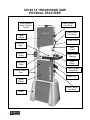
CX104 14” WOOD BAND SAW User Manual TABLE OF CONTENTS General Safety Instructions -----------------------------------------------------------------Specific Safety Instructions -----------------------------------------------------------------Features -----------------------------------------------------------------------------------------Physical Features ------------------------------------------------------------------------------ 3 4 5 6 Un-packing --------------------------------------------------------------------------------------- 7 Setup ---------------------------------------------------------------------------------------------- 7 Proper Grounding ------------------------------------------------------------------------------ 8 Assembly-----------------------------------------------------------------------------------------Blade Tracking Adjustment -----------------------------------------------------------------Basic Controls ----------------------------------------------------------------------------------Test Run -----------------------------------------------------------------------------------------Dust Collection ---------------------------------------------------------------------------------Speed Change Settings ----------------------------------------------------------------------Support Bearing Adjustments---------------------------------------------------------------Blade Tension ----------------------------------------------------------------------------------Table Adjustment ------------------------------------------------------------------------------Table Tilt Scale ---------------------------------------------------------------------------------Table Alignment --------------------------------------------------------------------------------ON/OFF Switch---------------------------------------------------------------------------------Work-piece Inspection (Wood) -------------------------------------------------------------- 9 12 13 14 14 15 15 17 17 18 18 19 19 Operations ---------------------------------------------------------------------------------------Ripping -------------------------------------------------------------------------------------------Cross Cutting -----------------------------------------------------------------------------------Re-Sawing ---------------------------------------------------------------------------------------Cutting Curves----------------------------------------------------------------------------------- 20 20 20 21 21 Maintenance ------------------------------------------------------------------------------------Removing/Installing Blade -------------------------------------------------------------------Cleaning and Lubrication --------------------------------------------------------------------V-Belt ---------------------------------------------------------------------------------------------Removing/Replacing the V-Belt ------------------------------------------------------------CX104 Optional Accessories ---------------------------------------------------------------- 22 22 23 23 23 24 Parts Breakdown and Parts List----------------------------------------------------------- 25-30 Warranty ------------------------------------------------------------------------------------------ 31 2 GENERAL SAFETY INSTRUCTIONS Extreme caution should be used when operating all power tools. Know your power tool, be familiar with its operation, read through the owner’s manual and practice safe usage procedures at all times. ALWAYS read and understand the user manual before operating the machine. DISCONNECT the power source when changing blade and / or making adjustments. CONNECT your machine ONLY to the matched and specific power source. NEVER leave a tool unattended while it is in operation. ALWAYS wear safety glasses respirators, hearing protection and safety shoes, when operating your machine. NEVER reach over the table when the tool is in operation. DO NOT wear loose clothing or jewelry when operating your machine. A SAFE ENVIRONMENT is important. Keep the area free of dust, dirt and other debris in the immediate vicinity of your machine. BE ALERT! DO NOT use prescription or other drugs that may affect your ability or judgment to safely use your machine. ALWAYS keep blades, knives and bits sharpened and properly aligned. ALL OPERATIONS MUST BE performed with the guards in place to ensure safety. ALWAYS use push sticks and feather boards to safely feed your work through the machine. ALWAYS make sure that any tools used for adjustments are removed before operating the machine. 3 CX104 14” WOOD BAND SAW SPECIFIC SAFETY INSTRUCTIONS CX104 is designed for cutting wood only. ALWAYS INSPECT the blade for any cracked or missing teeth before operating the band saw. ALWAYS ENSURE that the blade tension is properly set for the type and width of blade installed. NEVER place your fingers or hands in the line of cut. If you slip, your hands or fingers may come into contact with the blade. Always use a push stick when ripping narrow pieces. DO NOT back the work-piece away from the blade while cutting. Always turn off the machine if you are backing out a cut. ALL GAURDS must be in place while operating the band saw to ensure safety. ALWAYS FEED the stock smoothly. Do not force or twist the work-piece while cutting. ALWAYS ENSURE that the band saw blade guard is no more than 1/2” above the stock. MAKE SURE before making any adjustments, the switch is in the “OFF” position and the cord is un-plugged from the power source. NEVER LEAVE the band unattended while it is running. saw DO NOT attempt to remove jammed pieces unless the band saw has come to a complete stop and the power switch has been turned to the OFF position. NEVER TURN ON the band saw if the blade is in contact with your stock. ALWAYS ENSURE that the guide blocks are properly set to prevent blade wander. ALWAYS MAKE CERTAIN that the bearings are properly adjusted to guide the blade. MAINTAIN AND SERVICE your band saw regularly as instructed in the user manual. MAKE SURE you have read and understood all the safety instructions in the manual and you are familiar with your band saw, before operating the CX104. If you fail to do so, serious injury could occur. WARNING The safety instructions given above can not be complete because the environment in every shop is different. Always consider safety first as it applies to your individual working conditions. 4 CX104 WOOD BAND SAW FEATURES MODEL CX104 14” 1-HP BAND SAW As part of the growing line of Craftex CX-Series machineries, we are proud to offer the CX104 a 14” Wood Band Saw. The Craftex name guarantees Craft Excellence. By following the instructions and procedures laid out in this user manual, you will receive years of excellent service and satisfaction. The CX104 is a professional tool and like all power tools, proper care and safety procedures should be adhered to. Motor....................................................1-HP, 110-V, Single Phase Switch ..................................................ON/OFF Switch 2 Speeds..............................................2300 / 3200 FPM Cast Iron Table Size ............................14” x 18” ( Including Extension Table) Table Tilt ..............................................-5° to 45° Wheel Construction..............................Precision Balanced Cast Iron Max Blade Width..................................3/4" Min Blade Width...................................1/8” Maximum Cutting Height......................7” Floor to Table Height ...........................44” Cutting Capacity/Throat .......................13-5/8” Dust Collection Port .............................4” Blade Length .......................................101” Bearings...............................................Sealed and Permanently Lubricated Computer Balanced Cast Iron Wheels........Yes Co-Planer Adjustment..........................Yes Powder Coated Paint ...........................Yes Quick Release Tension Adjustment .....Yes Overall size ..........................................20” x 33” x 74” Approximate Weight.............................78 Kg Warranty ..............................................3 Years 5 CX104 14” WOOD BAND SAW PHYSICAL FEATURES Quick Release Blade Tension Handle Upper Cabinet Upper Cabinet Lock Knob Blade Guide Lock Knob Blade Guide Cast Iron Table Blade Guard ON/OFF Switch Extension Table Powder Coated Paint Blade Guide Bearings Miter Gauge Table Trunnion Lock Knob Dust Port Lower Cabinet Lower Cabinet Lock Knob Stand 6 UNPACKING The machine is properly packaged in a carton for safe transportation. When unpacking, carefully inspect the carton and ensure that nothing has been damaged during transit. While doing the inventory if you can not find any part, check if the part is already installed on the machine. K. L. M. N. O. P. Q. Dust Port Assembly .......................... Table Insert ....................................... Table Trunnion Lock Knobs .............. Stop Paddle ...................................... Table Stop Bolt ................................. Rubber Feet for Stand ...................... Hardware Bag (s).............................. 1 1 2 1 1 4 2 SETUP The unpainted surface of the table is coated with a rust preventive waxy oil and you will want to remove this before you begin assembly. Use a solvent cleaner that will not damage painted surfaces. When setting up your machine, you will want to find an ideal spot where your band saw will most likely be positioned most of the time. Consider your complete work environment before placing your machine in the ideal spot. Figure-1 Inventory LIST OF CONTENTS A. B. C. D. E. F. G. H. I. J. Band Saw.......................................... Legs .................................................. Panels ............................................... Motor ................................................. Motor Pulley ...................................... Extension Table ................................ Table ................................................. Table Lock Pin .................................. Table Trunnion .................................. Miter Gauge ...................................... 1 2 2 1 1 1 1 1 1 1 Figure-2 Minimum work space for CX104 WARNING CX104 is a heavy machine. Do not overexert yourself. Use a fork truck or get the help of an assistant or a friend. 7 PROPER GROUNDING Grounding provides a path of least resistance for electric current to reduce the risk of electric shock. CX104 is for use on a normal 110 volt circuit. Make sure that the machine is connected to an outlet having the same configuration as the plug. If an adaptor plug is used, it must be attached to the metal screw of the receptacle. To prevent electrical hazards, have a qualified electrician ensure that the line is properly wired. The band saw should be wired with a plug having 3 prongs to fit a 3 prong grounded receptacle as shown in figure-3. Do not remove the grounding prong to fit it into a 2 pronged outlet. Figure-3 110-Volts outlet for CX104 8 WARNING Improper connection of the equipmentgrounding conductor can result in a risk of electric shock. Check with a qualified electrician if you are in doubt as to whether the outlet is properly grounded. It is strongly recommended not to use extension cords with your CX104. Always try to position your machine close to the power source so that you do not need to use extension cords. In case if you really find it necessary to use an extension cord, make sure the extension cord does not exceed 50-feet in length and the cord is 14-gauge to prevent motor damage. ASSEMBLY To assemble the CX104 band saw, follow the instructions given below. Now, place the stand upside down and install the rubber feet to the stand as shown in figure-6 using screws provided. Attach the two panels to one of the legs as shown in figure-4 using screws, washers and nuts provided. Do not tighten at this time. Figure-6 Installing the rubber feet Figure-4 Attaching the panels to the leg Attach the second leg to the panels as shown in figure-5 using screws, washers and nuts provided. Make sure the panels and the legs are attached properly and tighten all the screws and nuts. Figure-5 Installing the second leg IMPORTANT You have to mount the motor to the band saw base before installing the band saw on the stand. Remove the protective plastic on the motor shaft. Position the pulley on the shaft, until it is flush with the end of the shaft and tighten the set screw. See Figure 7. Figure-7 Installing the motor pulley 9 Now, take the band saw out of the box and lay it on its side on the floor with the motor mounting side up as shown in fingure-8. You can place the carton on the floor under the band saw preventing it from getting scratched. Place the stand and the band saw upright. Get the help of a friend or assistant and lift the machine and place it on the stand. Align the mounting holes on the machine with the holes on the stand and secure the machine on to the stand using washers and bolts provided. See figure-10. Figure-8 Band saw on the floor Position the motor on the band saw and carefully insert the motor pulley through the hole as shown in figure-9. Align the holes on the motor mounting bracket with the holes on the band saw base. Insert the carriage bolts from under the base through the holes, place washers, and tighten the nuts provided onto the carriage bolts. Do not fully tighten the nuts at this time. Figure-10 Securing the machine onto the stand Open the lower cabinet door and position the V-belt onto one of the grooves on the idler pulley. Figure-11 Installing the V-belt Figure-9 Mounting the motor 10 Now pull the V-belt and position it onto the aligned groove on the motor pulley and tighten the motor mounting nuts shown in figure-9. Once the motor is mounted, connect the power coming from the motor to the power cord from the machine. Do not connect the machine to the power source at this time. Figure-14 Attaching the extension table to the table Figure-12 Connecting the cords Install the table trunnion to the machine and tighten the bolts using a wrench. See figure-13. Align the table slot with the blade and turn the table around until the blade is in the center of the table. Rest the table on the trunnions so that bolts protrude through from the bottom of the trunnions. Thread the lock knobs on to the bolts and secure the table on the trunnions. See figure-15. Figure-13 Installing the table trunnion and table stop bolt Thread the table stop bolt into the predrilled hole on the machine. See figure-13. Figure-15 trunnions Securing the table on the Attach the extension table to the table as shown in figure-14 and secure it using screws, washers, and nuts provided. 11 Install the table insert in the center of the table and the table lock pin to the end of the table slot as shown in figure-16. BLADE TRACKING ADJUSTMENT The blade tracking refers to where blade rides on the upper and lower wheels. The blade should always be centered on both wheels. Although the blade tracking of this band saw is factory set, you should check it again to make sure that the blade is centered on the wheels. The blade tracking can be controlled by adjusting the upper wheel tilt lock knob. See figure-18. Figure-16 Installing the table insert and table lock pin Attach the dust port to the machine and secure it using screws provided. See figure17. TO CHECK AND ADJUST THE BLADE TRACKING: Disconnect the machine from the power source and open the upper wheel cover. Rotate the upper wheel by hand slowly and see how the blade rides on the wheel. If the blade is not properly aligned and needs to be adjusted, loosen the lock nut shown in figure-18 and turn the knob. IMPORTANT Figure-17 Installing the dust port 12 In very rare cases if the blade tracking is not adjusted by tilting the upper wheel, then you will have to make minor adjustments to the angle of tilt of the lower wheel. Loosen the four hex bolts and rotate the sleeves to tilt the lower wheel to get the proper angle of tilt and tighten the bolts back. Remember, this adjustment is done only if the blade tracking is not adjusted by tilting the upper wheel. BASIC CONTROLS The basic controls of this machine are shown in the figure below. Use the figure and read the text to understand what the basic controls of this band saw are. Figure-18 Blade tracking adjustment knob TURN THE KNOB CLOCKWISE: If the blade moves towards the front edge of the wheel. It makes the top of the wheel to tilt back and moves the blade towards the center. TURN THE KNOB ANTI-CLOCKWISE: If the blade moves towards the back edge of the wheel. It makes the top of the wheel to tilt to the front and moves the blade towards the center. When you have adjusted the blade tracking, retighten the lock nut. Figure-19 Basic controls of CX104 A. The ON/OFF switch turns the band saw ON and OFF. B. The blade guide assembly lock knob secures the blade guide in position. Raise or lower the blade guide assembly and tighten the lock knob to secure the blade guide assembly in position. C. The quick release blade tension lever increase or decreases blade tension when rotated. IMPORTANT Make sure you have done the tracking adjustment and the blade is centered on the wheels before you start the band saw for a test run. See page-11 for details on blade tracking. 13 TEST RUN DUST COLLECTION Once you have assembled your machine completely, it is then time for a test run to make sure that the machine works properly and is ready for operation. The CX104 features a 4” diameter dust port to collect to a dust collector. Remove all the tools used for assembling the machine components. Walk around the machine, ensure all nuts, bolts, and screws are tightened and the machine is properly assembled. Connect the cord to the power source and turn the machine ON. When using a dust collector, use the proper sized hose and make sure all the connections are sealed tightly. It is recommended to use a proper sized dust collector with CX104 to ensure adequate dust collection. During the test run if there is any unusual noise coming from the machine or the machine vibrates, turn OFF the power switch immediately and disconnect the cord from the power source. Investigate if you can find out the problem with your machine. READ THE MANUAL Before starting the band saw, make sure that you have read and understood the manual and you are familiar with the functions and safety features on this machine. Failure to do so may cause serious personal injury. WARNING This machine can perform many types of operations which are beyond the scope of this manual and are very dangerous if performed incorrectly. The safety instructions given in this manual can not be complete because the environment in every shop is different. Always consider safety first as it applies to your individual working conditions. 14 Figure-20 Dust port WARNING The saw dust produced by the band saw can go into your lungs and cause serious health problems. Make sure the band saw is connected to a dust collection system while operating it. SPEED CHANGE SETTINGS To set the band saw to a speed of 2300 FPM, line up the drive belt on the second step of pulleys. See figure-22. The CX104 features 2-speed settings; 2300 FPM and 3200 FPM. To set the band saw to a speed of 3200 FPM, line up the drive belt on the first step of the pulleys. See figure-22. WARNING Before attempting any speed changes make sure the switch is in the OFF position and the cord is disconnected from the power source. Failure to do so could in serious injury or damage to the machine. Once you have positioned the drive belt on the pulleys, retighten the motor mounting nuts securing the motor in position. The motor pulley and the idler pulley are both 2-step pulleys. The band saw speed can be changed by loosening the motor mounting nuts and loosening the tension on the drive belt. Figure-22 Belt positions for speed change SUPPORT BEARINGS ADJUSTMENT Figure-21 Motor mounting nuts Once the motor mounting nuts are loosened, open the lower cabinet door and lift the motor up. The drive belt will be enough loosen to move it between the pulleys. The guide bearings (beside) and thrust bearing (behind) the blade, support the blade to move in a straight line during cutting operation. Properly adjusted support bearings play an important role in getting accurate cuts. Remove the blade guard and use an Allen key to loosen the set screws securing the bearings shown in figure-23. 15 Figure-23 Loosening the guide bearings screws Figure-25 Support bearings adjustment Use a screw driver and adjust the bearings so that the space between the bearing and the blade should be 0.02” which is thickness of a sheet of paper. See figure24. TO ADJUST THE LOWER SUPPORT BEARINGS: Figure-24 Distance between the guide bearings and the blade Figure-26 Guide block thrust bearing and guide blocks Now, retighten the set screws to lock the guide bearings in place. Loosen the set screws securing the guide blocks rod and the thrust bearing rod and adjust them so that the thrust bearing is 1/64” and the guide blocks are 1/32” behind the blade. Re-tighten the set screws. Loosen the thumb screws shown in figure25 and move the bearing shafts in or out so that the guide bearings are 1/32” and the thrust bearing is 1/64” behind the blade. Once the bearings are at the correct position, tighten the thumb screws to lock the bearings in place. 16 Loosen and remove the two table knobs located under the table and uninstall the table. Loosen the set screws securing the guide blocks and adjust the guides approximately 0.02” away from the blade and re-tighten the set screws. BLADE TENSION A properly tensioned blade is very important to get the best performance from any band saw. If the blade is too loose there is a possibility that the blade will slip or drift off the line while in operation and it will be hard to have accuracy in the line of cut. If the blade is tensioned too tightly, it will be very difficult to make tighter radius cuts and there will be a great possibility of blade breakage. When using a wider blade for making straight cuts, for re-sawing or making wide radius cuts, tighter blade tension is recommended; while using narrower blades for cutting shorter stock or making tighter radius cuts, less blade tension is recommended. IMPORTANT The information above is just a guideline for you to understand to set the blade tension according to the cut. However, understanding the blade tension adjustment comes with practice. IMPORTANT To prolong the life of the blade and reduce blade stretching, when the machine is not in use for period of 24 hours or more release the tension on the blade. TABLE ADJUSTMENT CX104 features a table stop which allows the table to easily come to 90° if the table is tilted. To adjust the table stop so that the table sits at 90°, you should first make sure the switch is in “OFF” position and the power cord is unplugged. Loosen the two table lock knobs under the table. Place a square on the table as shown in figure-28. BLADE TENSION ADJUSTMENT To adjust the blade tension, turn the blade tension handle shown in figure-27 clockwise to increase the blade tension and counter-clockwise to decrease it. To release tension simple lift the handle up. Figure-28 Table adjustment Figure-27 Blade tension adjustment Loosen the lock nut on the table stop bolt and thread the table stop bolt in or out so that the square is touching the table and the blade with its full length and the table is at a 90° with the blade. 17 TABLE ALIGNMENT To make accurate cuts with your band saw, the table should be aligned properly with the blade. TO ALIGN THE TABLE: Make sure the blade tension and tracking is done correctly. Figure-29 Table stop bolt Once the table is at 90° with the blade, retighten the lock nut and the table lock knobs. Disconnect the machine from the power source and loosen the table lock knobs under the table. Place a straightedge on the table so that the straightedge touches the blade and is parallel to it as shown in figure-31. Make sure the straight-edge touches only the flat part of the blade, not the teeth. TABLE TILT SCALE To calibrate the table tilt scale: Make sure the table is at 90° to the blade and the blade tensioning and tracking is properly set. (See Page 12 & page 17 for details) Loosen the screw on the pointer shown in figure-30. Align the tip of the pointer with the “0” mark on the tilt scale and tighten the pointer screw. Figure-31 Checking the table alignment Now, use a ruler to measure the distance between the miter slot and the straightedge on both sides (R & L) on the table. See figure-31. Figure-30 Table tilt scale 18 Loosen the table lock knobs and adjust the table until the distance on both sides of the table is equal and re-tighten the table lock knobs. ON/OFF SWITCH The CX104 is equipped with an ON/OFF switch featuring a large STOP paddle and a locking pin. WORKPIECE INSPECTION (WOOD) Before cutting any wood, make sure to inspect the work-piece for nails, staples, small pieces of stone or metal and any other foreign object which is dangerous to come on contact with the blade. If the wood contains any of these objects and it comes in contact with the blade, the object might fly and hit the operator or seriously damage the blade. For safety, always inspect your work-piece carefully before cutting and wear eye protection. Figure-32 ON/OFF switch with locking pin on CX104 Push the green “ON” button to turn the band saw on. Push the red “STOP” button to turn the band saw off. Insert the locking pin into the hole on the switch when the band saw is not used for a long period of time. This locks out the “ON” button so the band saw does not run. When you want to turn the band saw on, simply remove the locking pin and push the “ON” button. The locking pin on the switch allows preventing the band saw from unauthorized use. Some woods with excessive twisting or wrapping are un-stable while cutting and are dangerous to cut because during operation the work-piece can move unexpectedly which can either damage the blade or hurt the operator. If the wood is slightly cupped, make sure the cupped face of the wood is held against the fence. If the bowed side of the workpiece is held against the fence, the workpiece will move while cutting. IMPORTANT The information above is just a guideline for you to understand how to cut a workpiece with slight cupping. If you are not sure and do not have any experience in cutting cupped stock, do not cut it. Failure to follow these instructions might bring personal injuries to the operator or serious damage to the blade. Some stock with large knots can damage the blade and wet stock will give a poor result. 19 OPERATIONS Before operating the band saw make sure you have performed the following adjustments: Blade tension adjustment Blade tracking adjustment Support bearings adjustment Figure-33 Ripping on CX104 Make sure all the guards are in place WARNING The saw dust produced by the band saw can go into your lungs and cause serious health problems. Make sure the band saw is connected to a dust collection system while operating it. WARNING Do not use your fingers to feed narrow work-pieces into the blade. If you slip, your fingers might come close the blade. Always use a push stick. CROSSCUTTING RIPPING Cutting solid wood with the grain cutting down the length of the work-piece is called ripping. Adjust the fence on the rails, according to the width of the cut on the work-piece and turn the hand-wheel to set the guide post assembly 1” above the work-piece. Now, turn the band saw ON and use a push stick pushing the work-piece against the blade. See figure-33. 20 Cutting solid wood across the grain and in plywood or metal cutting across the width of the work-piece is called crosscutting. Mark the work-piece where you want to start the cut from and make sure the miter gauge is at 90° position on the miter slot. Place the work-piece on the table so that the marked point is aligned with the blade and hold the work-piece against the miter gauge. Turn the band saw ON and feed the workpiece against the blade. See figure-34 CUTTING CURVES For cutting curves always try to use narrower blades. When cutting curves feed the stock into the blade and turn it very carefully so that the blade follows the line of cut and make sure the blade does not twist. Make relief cuts through the waste part of the work-piece which makes the job easier and prevents the blade from twisting. Figure-34 Crosscutting on CX104 WARNING RESAWING Cutting a work-piece into two or more thinner pieces is called resawing. Wider blades give better result, when resawing. When installing / removing and servicing any part of the machine, make sure the power switch is in the off position and the cord is disconnected from the power source. Failure to do so may result in serious personal injury or death. To resaw a work-piece make sure that the table is at a 90° with the blade and use a wider blade for better results. Adjust the fence according to the width of the cut you want, and lock it in position. Turn the band saw ON and feed the workpiece into the blade using feed paddles until the blade is completely through the workpiece. Figure-35 Resawing on CX104 21 MAINTENANCE During the life of your machine, you will need to practice some regular maintenance to keep your saw in peak performance condition. REMOVING THE BLADE To remove / change the blade, turn the switch OFF and disconnect the cord from the power source. Release the blade tension lever, and remove the table insert and the table pin. Figure-36 Installing the new blade Open the upper and lower wheel cabinets and carefully slide the blade off the both wheels. Close the top and bottom cabinets and install the table pin and table insert back. Now, slide the blade out, through the slot on the table wearing gloves. INSTALLING THE BLADE Once the old blade is removed, carefully slide in the new blade through the slot on the table so that the teeth of the blade are pointing downwards. Position the blade through the upper and lower guide bearings and install it over the wheels. Once the blade is installed perform the following adjustments: Bade tension adjustment Blade tracking adjustment Support bearings adjustment 22 WARNING When installing / removing and servicing any part of the machine, make sure the power switch is in the off position and the cord is disconnected from the power source. Failure to do so may result in serious personal injury or death. The blade and table alignments should often be checked, and make sure the blade is at a 90° with the table. See page-18 Table Alignment” for details. CLEANING AND LUBRICATION The moisture from the wood dust remains on the table surface and can cause rust. Protect the un-painted cast iron surfaces of the table by cleaning the dust and wiping with a piece of cloth after every use. Apply a protective coating after. Wear a pair of gloves and carefully remove the blade. Uninstall the lower wheel by removing the hex nut securing the wheel to the saw body. See figure-37. If the table becomes harder to tilt, remove the table and apply a few drops of oil on the trunnions. V-BELT The V-belt stretches with use, and should be re-tensioned periodically. To ensure optimum power transfer from the motor to the blade, the belt must be in good condition and under proper tension. Check the V-belt at least after every 3 months and more often if the band saw is used daily. Figure-37 Lower wheel and pulleys Loosen the motor mounting nuts shown in figure-38 and lift the motor up to remove the belt from the pulleys. TO INSPECT THE V-BELT: Turn the power switch off and disconnect the cord from the power source. Open the lower cabinet and check the Vbelt for cracks or any other kind of damage. If the belt is damaged, it needs to be replaced. TO REPLACE THE V-BELT: Lift the blade tension handle up and release the blade tension. Remove the table insert and the table lock pin and open the upper cabinet. Figure-38 Motor mounting nuts Install the new belt and re-tighten the motor mounting nuts. Re-install the wheel, the hex nut, the blade, the table insert, the table lock pin and close the cabinets. 23 CX104 OPTIONAL ACCESSORIES BLADES ITEMS CX104018 CX104014 CX104038 CX104012 CX104034 LENGTH SIZE 101” 101” 101” 101” 101” 1/8” 1/4" 3/8” 1/2" 3/4" BLADES FENCE MODEL - KMS7200 KREG BAND SAW FENCE MODEL - KMS7200 MOBILE BASE MODEL - D2057A MOBILE BASE 18.5”X 20”–29”X29” MODEL - D2057A MODEL – HTC2000 UNIVERSAL MOBILE BASE 12”– 52” - 500LB MODEL - HTC2000 SAFETY MODEL - CT165 FINGER PROTECTOR FOR BAND SAW MODEL - CT165 24 CX104 BODY PARTS BREAKDOWN 25 CX104 BODY PARTS LIST REF# DESCRIPTION REF# 101 HEX BOLT 5/16-18P*1" WASHER5/16-16 8*16 SPRING1.2*8.5*4*13 BRACKET BAR SETTING PLATE FLAT WASHER5/16-20*2.0mm SPECIAL WASHER BODY SPECIAL NUT3/8*4*40 SPRING3.8mm*76*18 QUICK HANDLE BAR BEARING COVER HEX BOLT 8mm*118,1.25P LOCK NUT M8-P1.25 UPPER WHEEL BASE UPPER WHEEL BASE Upper Wheel - Cast Iron C-RING R35 BEARING 6202ZZ2 FLAT WASHER 1/4-16*1.2mm TIRE BLADE 0.65*10*6T*101 " LOCK WASHER 1/4 " UPPER WHEEL GUARD PIN SWITCH W/LARGE STOP SCREW 3/16*3/8 SCREW 3/16*3/4 KNOB 5/16*2 " HEX NUT 5/16-18P " HEX NUT 1/2-20P" LOCK WASHER 1/2" 133 102 103 104 105 106 107 108 109 110 111 112 114 115 116 117 118 119 120 121 122 123 124 125 126 127 128 128A 129 130 131 132 26 134 134A 135 136 137 138 139 140 141 142 143 144 145 146 147 148 149 150 151 152 153 154 155 156 157 158 159 160 161 162 163 DESCRIPTION V-BELT M28 CAP SCREW 1/4-20P*3/8" " HEX BOLT 1/4-20*3/8" " BEARING 6004ZZ KEY 5*5*35MM LOWER SHAFT LOWER WHEEL -CAST IRON HEX NUT 3/4-16P(L.H.) " LOWER WHEEL GUARD HEX BOLT 3/8*3 HEX NUT 3/8-16P HEX BOLT 5/16-18P*3/4" " LOCK WAWHER 5/16 " PIN 6*16mm GUARD LOCKING KNOB PHILLIPS HEAD SCREW 1/4*3/4 STRAIN RELIEF KNOB BOLT5/16*1 " CORD CORD CORD WASHER 3/16 HEX NUT 3/16 " HEX BOLT 5/16-18P*1 " ADJUSTING SCREW NUT 5/8 BEARING HOUSING DUST PRRT 2.5" SET SCREW 1/4-20P*1/4" " WHEEL PULLEY HEX BOLT 1/4-20P*3/4" HEX NUT 1/4-20P" CX104 STAND & MOTOR PARTS BREAKDOWN 27 CX104 STAND & MOTOR PARTS LIST REF# 201 202 204 205 206 207 208 213 214 215 216 217 218 220 221 28 DESCRIPTION SCREW 5/16*2 FLAT WASHER5/16-20*2.0mm MOTOR HEX NUT 5/16-18P" LOCK WASHER 5/16" FLAT WASHER 5/16-20*2.0mm CARRIAGE BOLT 5/16*1" MOTOR PULLEY 15" SET SCREW 1/4-20P*1/4" " STAND PANEL STAND SIDE RUBBER FEET 5/16" HEX BOLT 5/16*3/4" WASHER 5/16-16 8*16 CARRIAGE BOLT CX104 TABLE PARTS BREAKDOWN 29 CX104 TABLE PARTS LIST REF# 301 303 304 305 306 307 308 309 310 311 312 313 314 315 316 317 318 319 319 320 320 321 322 30 DESCRIPTION GUIDE POST 295mm HEX BOLT 1/4*1/2 " BLADE COVER THUMBSCREW 1/4*3/4 FLAT WASHER 1/4" HEX BOLT 1/4-20P*3/8 " TABLE TAPERED PIN0 6*38MM HEX BOLT 3/8*2" TRUNNION CLAMPSHOE TRUNNION HEX BOLT 1/4-20P*3/4" HEX BOLT 1/4-20P*3/4" " SET SCREW 1/4-20P*1/4" TABLE BRACKET LOCK KNOB F/TABLE 3/8 #40 SUPPORT BRACKET 7/8ID" HEX SHAFT V2.10.09 HEX SHAFT V2.10.09 BEARING 6200ZZ BEARING 6200ZZ EXTERNAL RETAINING RING GUIDE BLOCK HOLDER REF# 323 325 326 327 327A 328 328A 329 330 331 332 333 334 335 336 DESCRIPTION BLADE GUIDE BLOCK ROUND TABLE INSERT ALUMINUM GAUGE HEX BOLT 5/16-18P*1 1/4 " HEX BOLT 5/16-18P*1 1/4 " FLAT WASHER 5/16 HEX NUT 5/16(12*6) POINTER PHILLIPS H.D SCREW 3/16*1/4 SUPPORT BRACKET LOWER MITER GAUGE-19m/m-T BEARING SHAFT SUPPORT EXTENSION TABLE HEX BOLT 1/4-20P*3/4" " WARRANTY CRAFTEX 3 YEARS LIMITED WARRANTY Craftex warrants every product to be free from defects in materials and agrees to correct such defects where applicable. This warranty covers three years for parts and 90 days for labour (unless specified otherwise), to the original purchaser from the date of purchase but does not apply to malfunctions arising directly or indirectly from misuse, abuse, improper installation or assembly, negligence, accidents, repairs or alterations or lack of maintenance. Proof of purchase is necessary. All warranty claims are subject to inspection of such products or part thereof and Craftex reserves the right to inspect any returned item before a refund or replacement may be issued. This warranty shall not apply to consumable products such as blades, bits, belts, cutters, chisels, punches etceteras. Craftex shall in no event be liable for injuries, accidental or otherwise, death to persons or damage to property or for incidental contingent, special or consequential damages arising from the use of our products. RETURNS, REPAIRS AND REPLACEMENTS To return, repair, or replace a Craftex product, you must visit the appropriate Busy Bee Tools showroom or call 1800-461-BUSY. Craftex is a brand of equipment that is exclusive to Busy Bee Tools. For replacement parts directly from Busy Bee Tools, for this machine, please call 1-800-461-BUSY (2879), and have your credit card and part number handy. All returned merchandise will be subject to a minimum charge of 15% for re-stocking and handling with the following qualifications. Returns must be pre-authorized by us in writing. We do not accept collect shipments. Items returned for warranty purposes must be insured and shipped pre-paid to the nearest warehouse Returns must be accompanied with a copy of your original invoice as proof of purchase. Returns must be in an un-used condition and shipped in their original packaging a letter explaining your reason for the return. Incurred shipping and handling charges are not refundable. Busy Bee will repair or replace the item at our discretion and subject to our inspection. Repaired or replaced items will be returned to you pre-paid by our choice of carriers. Busy Bee reserves the right to refuse reimbursement or repairs or replacement if a third party without our prior authorization has carried out repairs to the item. Repairs made by Busy Bee are warranted for 30 days on parts and labour. Any unforeseen repair charges will be reported to you for acceptance prior to making the repairs. The Busy Bee Parts & Service Departments are fully equipped to do repairs on all products purchased from us with the exception of some products that require the return to their authorized repair depots. A Busy Bee representative will provide you with the necessary information to have this done. For faster service it is advisable to contact the nearest Busy Bee location for parts availability prior to bringing your product in for repairs. 31