1
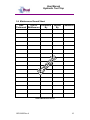
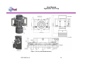
Unit 17 Denmore Industrial Estate, Denmore Road, Bridge of Don, Aberdeen AB23 8JW User Manual Hydraulic Tool Trap This Manual Covers the Following Part Numbers: 168-3655-HV0 OPS-3655 Rev A User Manual Hydraulic Tool Trap Table of Contents Revision History ............................................................................................. ii Safety ................................................................................................................ iii 1 Introduction .................................................................................................1 1.1 General ................................................................................................1 1.2 Product Identification ...........................................................................1 2 Technical Specification ...............................................................................2 3 Technical Description .................................................................................3 3.1 Collar Safe-Lok ....................................................................................3 3.1.1 Preparing the Safe-Lok Collar......................................................3 3.1.2 Making up the Safe-Lok Collar.....................................................4 3.1.3 Breaking the Safe-Lok Collar .......................................................5 4 Operation ....................................................................................................5 4.1 Pre Job ................................................................................................5 4.2 During Job ...........................................................................................6 4.3 Post Job...............................................................................................6 4.4 Tool Trap Operation ............................................................................6 5 Maintenance ...............................................................................................8 5.1 Introduction ..........................................................................................8 5.2 Schedule..............................................................................................8 5.2.1 Pre & Post Job .............................................................................8 5.2.2 Yearly ...........................................................................................8 5.2.3 Five Yearly ...................................................................................8 5.3 Safety ..................................................................................................8 5.4 Maintenance Record Sheet .............................................................. 15 6 Testing ..................................................................................................... 16 7 Parts List and Drawings........................................................................... 17 8 Spares ..................................................................................................... 19 Table 1: Technical Data .....................................................................................2 Table 2:Maintenance Record.......................................................................... 15 Table 3: Parts List 168-3655 HV0................................................................... 17 Table 4: Spares RDK-3655-HV0 .................................................................... 19 Figure 1: Tool Trap 165-3655-HV0 Assembly ................................................ 18 OPS-3655 Rev A i User Manual Hydraulic Tool Trap Revision History Issue, Release Date Rev A, OPS-3655 Rev A Description Initial Issue ii User Manual Hydraulic Tool Trap Safety WARNING: Trapped air requires considerable time to compress and when it is compressed is highly dangerous. It has enough stored energy to separate parts with considerable force. All pressure equipment has a particular pressure rating and care must be taken to ensure that no item is used in a situation that may cause its working pressure to be exceeded. All personnel involved in pressure testing must be formally trained, competent and utilise the appropriate PPE. Safe-Lok devices should be checked for positional security to avoid unnecessary movement of the collar. Ensure the identification band/plate is fitted and is displaying the correct information as per the Tag Sheet / Index This equipment and the equipment it is attached to is heavy never position yourself below a suspended load. Care should be taken to avoid entrapment of fingers, gloves and clothing during make up procedures OPS-3655 Rev A iii User Manual Hydraulic Tool Trap 1 Introduction 1.1 General The Phuel Hydraulic Tool Trap is used to prevent tool strings from inadvertently falling into the well. Positioned below the lubricator it offers hydraulic actuation for the release of the tool string. The equipment also has a built in frame which offers protection to the hydraulic components. This user manual serves as an introduction to the equipment and contains the relevant specifications, operation, planning and maintenance instructions, parts list and drawings. 1.2 Product Identification Phuel products are identified by a unique serial number that facilitates full product traceability. Each product is supplied with a documentation pack that contains product certification and material/inspection reports. The serial number is always etched on the surface of the product but can sometimes be difficult to find or read after painting. A customer identification number is also included to allow the customer to track the asset in their system. A stainless steel band secures the nameplate tag that is stamped with the information shown below. This tag should be located in the first instance to ensure that this manual refers to the correct equipment. OPS-3655 Rev A 1 User Manual Hydraulic Tool Trap 2 Technical Specification Part Number Connection Maximum Working Pressure Test Pressure Service Weight Overall Length Makeup Length 168-3655-HV0 11.5 – 4 Acme 10,000 Psi 15,000 Psi H2S 676 lbs/ 307 Kg 31.17’’/0.79m 24.49’’/0.67m Table 1: Technical Data OPS-3655 Rev A 2 User Manual Hydraulic Tool Trap 3 Technical Description The Phuel Hydraulic Tool Trap is a safety device. It is essentially a flapper type valve for tools, positioned just above the BOP it can be opened to allow tools to pass into the well. Once the tools have passed, the flapper can be closed, the milled slot allowing the wire to continue to move unhindered. When tools are brought back into the lubricator rig up they pass through the Tool Trap freely. However, as the tools string moves the flapper out of the way, the handle can be seen to move on the outside of the Tool Trap, giving a clear visual indication that the tools are in place. Should the tools be brought into the Lubricator rig up too quickly and hit the top, releasing them from the rope socket, the flapper prevents them falling any farther than the Tool Trap. The Hydraulic Tool Trap works in exactly the same way as a Manual Tool Trap except that the handle which is used to open the flapper is hydraulically actuated. The advantage is that control of all the Pressure Control Equipment can be made from a central location, and that nobody needs to be exposed to potential harm by working in close proximity to a high pressure or hostile environment. Note: The indicator arm is a positional indication of the internal flapper and is not to be used as a manual operating handle 3.1 Collar Safe-Lok The safe collar lock is designed to provide safe handling of the union collars. In addition it can be used to prevent accidental back off of the collar. The following shows the sequence for correct operation. 3.1.1 Preparing the Safe-Lok Collar After removing the thread protector the collar will be set in the lower position and must be moved to the high position before making up the connection. With both hands raise the collar ensuring the Stop Pins go through the gaps in the raised rim OPS-3655 Rev A 3 User Manual Hydraulic Tool Trap Rotate the collar through 90° and gently lower onto the raised rim. Ensure collar rests into the grooved area 3.1.2 Making up the Safe-Lok Collar Lift and stab the pin into the mating box and check that there are no signs of damage to the o-ring (caused by being misaligned while stabbing in). With both hands raise the collar clear of the grooved area on the raised rim and rotate through 90°. Lower the collar until it reaches the top of the threads. Turn the collar anticlockwise until the start of the thread is found and then start turning clockwise to make up the collar to the box thread. Tighten the collar down. OPS-3655 Rev A 4 User Manual Hydraulic Tool Trap 3.1.3 Breaking the Safe-Lok Collar Unscrew the collar completely Lift the collar up, ensure the stop pins go through the gaps in the raised rim. Rotate the collar 90° and lower gently so that the pins rest in the grooved portion of the raised rim. The connection can now separated without any risk dropping the collar. be of 4 Operation All operations to be carried out by suitably qualified and competent personnel 4.1 Pre Job Ensure thread protectors are fitted Check maintenance record sheet and ensure the equipment has been maintained by competent personnel Check all certification is in date Confirm information band is fitted and correct Ensure equipment is suitable for the maximum working pressures and services involved Ensure visible ‘O’ rings are seated correctly and there are no signs of damage Ensure threads are clean Inspect for signs of damage Pressure test to maximum well pressure OPS-3655 Rev A 5 User Manual Hydraulic Tool Trap 4.2 During Job Avoid excessive movement 4.3 Post Job Inspect for signs of damage Ensure threads are clean Ensure thread protectors are fitted 4.4 Tool Trap Operation Tool String The Flapper is held in the closed position by torsion springs therefore preventing the tool string passing through uncontrolled Flapper With no hydraulic pressure applied the Indicator arm and the Piston lever will be in the positions shown therefore indicating that the flapper is in the closed position Closed OPS-3655 Rev A 6 User Manual Hydraulic Tool Trap As hydraulic pressure is applied to the tool trap the Indicator arm position is representative of the position of the Flapper inside the tool When the Indicator arm is in the vertical position the Flapper is fully open thus allowing the operator to lower the tool string into the well Fully Open When the tool has been lowered a pre-determined distance, to ensure it has completely passed the Flapper, the hydraulics can be released allowing the Flapper to close Upon extraction of the tool string as the tool string makes contact with the Flapper it will simply push the Flapper out of the way allowing the tool string to be extracted. Once completely passed the tip of the Flapper the Torsion Springs will automatically close the Flapper this will be indicated on the outside of the tool by the simultaneous movement of the Indicator Arm OPS-3655 Rev A 7 User Manual Hydraulic Tool Trap 5 Maintenance All maintenance to be carried out by suitably qualified and competent personnel 5.1 Introduction Regular maintenance of the equipment using Phuel redress kits or Phuel approved parts is essential to its continued safe operation. Ensure that the pre and post job operating procedures are followed and that maintenance records are kept. 5.2 Schedule The maintenance schedule may be governed by international or company standards and the following are considered to be the minimum requirements. 5.2.1 Pre & Post Job 5.2.2 Yearly Disassemble Equipment clean and degrease all components Inspect the condition of all sealing surfaces and surface coatings Re-coat threads and sealing surfaces if necessary. If in doubt contact Phuel Oil Tools Ltd Replace all elastomeric seals with items from redress kit (see spares Error! Reference source not found.) Regrease components Re-assemble Pressure test to maximum working pressure in accordance to testing procedure Inspect paint work and repair as necessary 5.2.3 Five Yearly Yearly Maintenance (plus the following) Carry out 100% surface NDE on all surfaces Pressure test to test pressure witnessed by verifying body 5.3 Safety Many of the components are heavy and should not be lifted without lifting aids. Ensure all pressure testing is carried out in the appropriate testing area by suitably qualified personnel. OPS-3655 Rev A 8 User Manual Hydraulic Tool Trap Wear appropriate personal protective equipment. Do not over exert yourself while using torque wrenches. Use appropriate mechanical advantages when available. Ensure that all tools and equipment are in good condition and are suitable for the intended use. Clear up any fluid spills immediately to avoid slips. OPS-3655 Rev A 9 User Manual Hydraulic Tool Trap OPS-3655 Rev A 10 User Manual Hydraulic Tool Trap OPS-3655 Rev A 11 User Manual Hydraulic Tool Trap OPS-3655 Rev A 12 User Manual Hydraulic Tool Trap OPS-3655 Rev A 13 User Manual Hydraulic Tool Trap OPS-3655 Rev A 14 User Manual Hydraulic Tool Trap 5.4 Maintenance Record Sheet Date Type of Performed Performed Maintenance By Verified By Comments Table 2:Maintenance Record OPS-3655 Rev A 15 User Manual Hydraulic Tool Trap 6 Testing All testing is to be carried out in the designated test area and by suitably qualified and competent personnel. WARNING: Trapped air requires considerable time to compress and when it is compressed is highly dangerous. It has enough stored energy to separate parts with considerable force. Fit appropriate test cap and blanks Fill with testing fluid bleeding off any air within the system Apply a pressure of 500 psi and ensure pressure holds for a minimum of 10 minutes Increase pressure to 10,000 psi (Maximum Working Pressure), allow to stabilise and maintain this pressure until it is evident there are no apparent leaks.(Testing to be carried out to Test pressure when decreed by maintenance schedule) Bleed off pressure, drain test fluid and dry Remove test caps Apply coating of de-watering solution to protect the bore and threads Fit thread protectors On completion of all maintenance ensure the maintenance record sheet (5.4) is completed OPS-3655 Rev A 16 User Manual Hydraulic Tool Trap 7 Parts List and Drawings Item 1 2 3 4 5 6 7 8 9 10 11 12 13 14 15 16 17 18 19 20 21 22 23 24 25 26 27 28 29 30 100 110 Part Number 168-3830-480 168-3831-316 168-3832-50D 168-3833-316 168-3834-316 168-3835-316 168-3859-HV0 168-3839-PTF 168-3840-STL 168-3846-316 110-2546-480 110-2547-480 145-2176-480 168-3770-316 168-3854-316 168-3858-PTF 110-2548-3A4 802-3855-H80 801-0119-V90 801-0213-V90 801-0444-V90 SHC-0522-3A4 SHC-0559-3A4 SHC-0583-3A4 SHC-0585-HTS WNL-0520-316 WPL-0520-316 WNL-0540-316 WNL-0580-316 WLK-0520-304 910-3620-N66 910-3621-N66 Description 11.5"-4 TOOL-TRAP BODY ROTATION ROD 6-3/8" FLAPPER ROTATION ROD RETAINER INDICATING BAR PISTON LEVER TOOL TRAP PISTON ASSEMBLY SPACER TOOL TRAP FRAME (HALF) PISTON FOOT MOUNTING SPLIT COLLAR 11.5-4 SPLIT RING (11.5-4) SAVER SUB PORT TORSION SPRING (RIGHT SIDE) TORSION SPRING (LEFT SIDE) SPRING SPACER STOP PIN (1.25 LONG) ROD T-SEAL (0.620) O-Ring - B.S Size 119 O-Ring - B.S Size 213 O-Ring - B.S Size 444 Soc Hd Cap Size 5/16 Length 0.5 in SOC HD CAP SCREW 3/8" X 4 1/2" LONG Soc Hd Cap 1/2 UNC Length 3/4 in Soc Hd Cap Size 1/2 Length 1 in Washer Lock Size 5/16 WASHER PLAIN SIZE 5/16 Nord Lock Washer Size 3/8 WASHER NORDLOCK (M12) Washer Lock 5/16 DW MALE PROTECTOR 11 1/2 DW FEMALE PROTECTOR 11-1/2 Qty 1 1 1 2 1 1 1 2 2 1 1 1 1 1 1 2 4 2 1 2 1 4 2 2 8 2 2 2 14 2 1 1 Table 3: Parts List 168-3655 HV0 OPS-3655 Rev A 17 User Manual Hydraulic Tool Trap Figure 1: Tool Trap 165-3655-HV0 Assembly OPS-3655 Rev A 18 User Manual Hydraulic Tool Trap 8 Spares Use only spares supplied or approved by Phuel Oil Tools Ltd. It is recommended that sufficient quantities of the following spares be maintained to ensure that the equipment is always available when required. Elastomeric spares are supplied in Viton material as standard. Many other materials are available please specify when ordering. Part Number 802-3855-H80 801-0119-V90 801-0213-V90 801-0444-V90 Description ROD T-SEAL (0.620) O-Ring - B.S Size 119 O-Ring - B.S Size 213 O-Ring - B.S Size 444 Qty 2 1 2 1 Table 4: Spares RDK-3655-HV0 OPS-3655 Rev A 19