1
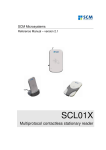
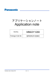
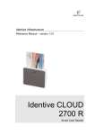
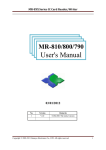
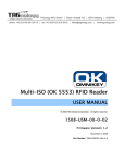
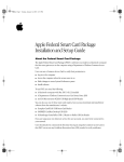
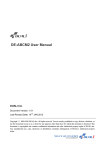
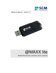
SPECIFICATION User Manual Model No. Date File Ver. Page CRT-603-CZ1 2013/08/15 1.0 1/39 CRT-603-CZ1 Contactless Card Reader Module User Manual (V1.0.0.0) CREATOR (CHINA) TECH CO., LTD ADD: 2/F, M-10 Building, Center Area, High-tech Industrial Park Shenzhen, Guangdong, China. Tel: +86-755-26710345 Fax: +86-755-26710105 EMAIL: [email protected] Http://www.china-creator.com SPECIFICATION User Manual CRT-603-CZ1 2013/08/15 1.0 2/39 Model No. Date File Ver. Page Version Date Note 1.0.0.0 2013.8.15 First release Glossary Acronym/Abbreviation Expansion APDU Application Protocol Data Unit ATR Answer to Reset, defined in ISO7816 ATS Answer to select, defined in ISO/IEC 14443 CCID Chip Card Interface Device CID Card Identifier CL Contact-Less FWT Frame Waiting Time Mifare The ISO14443 with extensions for security (PHILIPS) NAD Node Address PCD Proximity Coupling Device PCSC Personal computer Smart card PICC Proximity Integrated Chip Card RF Radio Frequency USB Universal Serial Bus SPECIFICATION User Manual Model No. Date File Ver. Page CRT-603-CZ1 2013/08/15 1.0 3/39 1 Overview 1.1 Product Description CRT-603-CZ1 is a USB dual interface card reader running on Windows including conctactless card interface and SAM card interface. The reader complies with PC/SC standard, ISO14443 standard applicable to type A and type B contactless cards and ISO14443-3 standard applicable to MIFARE series contactless cards. It also complies with ISO7816 standard related to SAM card. 1.2 1.3 Features Bus powered, USB 2.0 full speed PC/SC V2.0 compliant, CCID interface, support Windows XP and Windows 7 Contactless card interface, antenna and main board separated design SAM card reader interface, User can select one of the 2 SAM slot of the SAM card reader interface to operate Automatic search contactless card and peferctly handle multiple card conflict. Support ISO14443-4 type A&B contactless cards Support ISO14443-3 S50,S70 and UL etc contactless Storage Card. Support ISO7816 SAM card Firmware online update through USB ( supplier IAP tool provided ) DC 5V, static current 200mA, dynamic current 220mA, peak current 250mA EMC、QPBOC、EMV、CB、WHQL certified Operation environment: -10 -10℃ ~ 60℃, 0 ~ 95 % RH ( No condensing ); Humidity 5 to 95% ( No condensing ) TA<= 60℃ Storage Environment: -40℃ ~ 70℃, 0 ~ 95 % RH ( NO condensing ) ; Humidity 5 to 95% RH ( No condensing ) TA<= 70℃ USB Interface Card reader is connected to the host with a mini USB cable, PIN definition is as following: PIN Signal 1 VBUS 2 D3 D+ 4 ID 5 GND SPECIFICATION User Manual Model No. Date File Ver. Page CRT-603-CZ1 2013/08/15 1.0 4/39 2 Product Hardware 2.1 Product components The reader has 3 main components: ① Main board: including 2 SAM card slots and 1 USB interface, onboard power indicator, USB connection indicator, buzzer ② Antenna board: connected to main board with a 3 pins cable ③ LED board: Red, Green, Blue and Yellow LED lights, the LED board is connected to main board with a 6 pins cable SPECIFICATION User Manual 2.2 Model No. Date File Ver. Page Images of boards Main board Antenna board CRT-603-CZ1 2013/08/15 1.0 5/39 SPECIFICATION User Manual Model No. Date File Ver. Page CRT-603-CZ1 2013/08/15 1.0 6/39 LED board Reader function Note: Contactless card interface and SAM card interface are independent with each other. Reader supports operation in parallel. SPECIFICATION User Manual Model No. Date File Ver. Page CRT-603-CZ1 2013/08/15 1.0 7/39 2.2.1 Contactless Card interface function 1. Read/write ISO14443-4 standard Type A&B contactless card 2. Read/write ISO14443-3 standard Mifare one S50, S70 and UL etc contactless Storage Card 3.Reader will automatically detect whether a card is present. The card will remain to be activated without interfered by other new cards presented. 4. When more than one card enter detection area at the same time, cards will conflict with each other, the result caused by conflict is as following Card existence Detection result ATR reported One TYPE A card Detect one TYPE A card and activate the card TYPE A card ATR More than one TYPE A card One TYPE B card More than one TYPE B card One TYPE A and one TYPE B card More than one TYPE A and more than one TYPE B card Detect more than one TYPE A card, not able to activate any card Detect one TYPE B card and activate the card Detect more than one TYPE Bcard, not able to activate any card Detect more than one card, not able to activate any card Detect more than one card, not able to activate any card Special ATR ( indicate card conflict ) TYPE B card ATR Special ATR ( indicate card conflict ) Special ATR ( indicate card conflict ) Special ATR ( indicate card conflict ) 5.Contactless card reader also provides buzzer operation,LED operation, card reader restart, get firmware version and jump to IAP mode functions. User can use these functions by extended capabilities command and APDU commands defined by supplier. 2.2.2 SAM card reader interface function: 1.User can choose one SAM slot from the 2 SAM slots to read/write SAM card 2.’Disconnect Reader’ command’ will not power off SAM card slot. 3.SAM card reader interface provides change card slot, check SAM card board and SAM card slot status function (by use of extended capabilities commands) SPECIFICATION User Manual Model No. Date File Ver. Page CRT-603-CZ1 2013/08/15 1.0 8/39 3 Card Operation 3.1 Contact Card Environment Specifics Note: Only use the SAM card reader 3.1.1 ATR of SAM Card Reader report card present status will automatically to ICC Resource Manager after SAM card reset is successful. Card ATR will be sent to application after user sends ‘Change SAM Slot’ command and ‘Connect Reader’ command. 3.1.2 APDU Command of SAM Card Note: Please refer to COS document of the card for more detail APDU commands SPECIFICATION User Manual 3.2 CRT-603-CZ1 2013/08/15 1.0 9/39 Model No. Date File Ver. Page Contactless Card Environment Specifics Note: Only use the RF card reader 3.2.1 ATR of Contactless Card When the reader detects a contactless smart card, reader will report card present status to ICC Resource Manager automatically. Card ATR will be sent to application after user chooses RF reader and sends ‘Connect Reader’ command. 3.2.1.1 ATR of Contactless Smart Card Byte 0 1 Value 3B 8n Designation Initial Header T0 2 80 TD1 3 01 TD2 4 to 3+n XX XX XX T1 … .. Tk 4+n XX TCK Description Higher nibble 8 means no TA1, TB1, TC1 only TD1 is following. Lower nibble n is the number of historical bytes (HistByte 0 to HistByte n-1) Higher nibble 8 means no TA2, TB2, TC2 only TD2 is following. Lower nibble 0 means T = 0 Higher nibble 0 means no TA3, TB3, TC3, TD3 following Lower nibble 1 means T = 1 Historical bytes: ISO14443A: The historical bytes from ATS response. Refer to the ISO14443-4 specification. ISO14443B: Byte1-4---- Application Data from ATQB Byte5-7---- Protocol Info Byte from ATQB Byte 8 ----Higher nibble = MBLI from ATTRIB command Lower nibble (RFU) = 0 Exclusive-OR of bytes T0 to Tk Example: a. TYPE A card ATR :3B 8F 80 01 78 80 90 02 20 90 00 3F 38 70 04 B6 49 70 67 4F b. TYPE B card ATR: 3B 8C 80 01 50 20 02 22 52 55 55 55 55 00 81 C1 4F Note: When ISO14443A historical bytes T1-Tk greater than 15 bytes, the reader only reported to the last 15 historical bytes of data。 SPECIFICATION User Manual CRT-603-CZ1 2013/08/15 1.0 10/39 Model No. Date File Ver. Page 3.2.1.2 ATR of Contactless Storage Card Byte 0 1 Value 3B 8n Designation Initial T0 2 80 TD1 3 01 TD2 4 To 3+N 80 T1 4F 0C RID Tk 4+N SS C0 C1 00 00 00 00 UU Description RFU Higher nibble 8 means: no TA1, TB1, TC1 only TD1 is following. Lower nibble n is the number of historical bytes (HistByte 0 to HistByte n-1) Higher nibble 8 means: no TA2, TB2, TC2 only TD2 is following. Lower nibble 0 means T = 0 Higher nibble 0 means no TA3, TB3, TC3, TD3 following. Lower nibble 1 means T = 1 Category indicator byte, 80 means A status indicator may be present in an optional COMPACT-TLV data object Application identifier Presence Indicator Length Registered Application Provider Identifier (RID) # A0 00 00 03 06 Byte for standard Bytes for card name RFU # 00 00 00 00 TCK Exclusive-oring of all the bytes T0 to Tk C0 C1 is 0001 suggest the card is S50 card, 00 02 suggest S70 card, For example: S50 card ATR: 3B 8F 80 01 80 4F 0C A0 00 00 03 06 03 00 01 00 00 00 00 6A S70 card ATR: 3B 8F 80 01 80 4F 0C A0 00 00 03 06 03 00 02 00 00 00 00 69 Note: The naming method for other types of cards can be found in supplementary file in PC/SC section 3. When RF card conflicts with each other, returned ATR: 3B 8F 80 01 80 4F 0C A0 00 00 03 06 03 00 01 E0 00 00 01 8B SPECIFICATION User Manual Model No. Date File Ver. Page CRT-603-CZ1 2013/08/15 1.0 11/39 3.2.2 APDU Command of Contactless Card 3.2.2.1 Get Data Command Get UID or ATS of the contactless card Command format: Command Class Get Data 0xFF INS 0xCA P1 XX P2 0x00 Le XX Parameter Description: P1 = 0 UID is returned. P1 = 1 all historical bytes from the ATS of a ISO 14443 A card without CRC are returned. Le = 0x00, this means: Return full length of the data (e.g. for ISO14443A single 4 bytes, double 7 bytes, triple 10 bytes, for ISO14443B 4 bytes PUPI, for 15693 8 bytes UID). Return format: Data Out Data + SW1 SW2 SW1 SW2 STATUS CODE: SW1 Success 90 62 Fail 67 68 6A 6B 6C SW2 00 82 00 00 81 00 XX Example: A. Get UID APDU: Command: Command Class INS Get Data FF CA Return: Response Data Out Result UID …… (LSB) B. Get ATS APDU: Command: Command Class INS Get Data FF CA Return: Response Data Out Result ATS SW1 Meaning Command execution successfully End of data reached before Le bytes (Le is greater than data length). Wrong length Class byte is not correct Function not supported. Wrong parameter P1-P2 Wrong length (wrong number Le; 'XX' encodes the exact number) if Le is less than the available UID length) P1 00 UID (MSB) P1 01 SW2 P2 00 SW1 P2 00 Le 00 SW2 Le 00 SPECIFICATION User Manual Model No. Date File Ver. Page CRT-603-CZ1 2013/08/15 1.0 12/39 3.2.2.2 Smart Card Functionality Support Note: Please refer to COS document of the card for more detail APDU commands 3.2.2.3 Storage Card Functionality Support This section defines commands for Storage Cards (Exception: The Get UID and Load Key command, which may be used for all kinds of contactless cards): 3.2.2.3.1 Load Key (Password) The ‘Load key’ command will just load (write) the keys(Mifare key) in the IFD designated memory. 32 groups password can be saved into the IFD volatile memory and 1 group password can be saved into the IFD non-volatile memory Command format:: Command Class Load Keys 0xFF Parameter Description: P1: Bit Value 7 0 6 0 5 1 4 0~3 0000 INS 0x82 P1 Key Structure P2 Key number Lc Key Length Data In Key Description 0: Card Key; 1 Reader Key 0: Plain Transmission, 1: Secured Transmission 0: Keys are loaded into the IFD volatile memory 1: Keys are loaded into the IFD non-volatile memory. 0:Key type is KEY_A1:Key type is KEY_B , (for non-volatile memory.) If b6 is set, it is the Reader Key number that has been used for the encryption, else it is ignored by the IFD. The maximum of 16-reader keys is possible. Typically an IFD uses two reader keys only. P2: indicating Key number, range: 0x00~0x1F Return format: Data Out SW1 SW2 SW1 SW2 STATUS CODE: SW1 Success 90 Fail 63 67 68 69 SW2 00 00 00 00 82 83 85 88 89 Meaning Command execution successfully Command execution failed Wrong length Class byte is not correct Card key not supported Reader key not supported Secured transmission not supported Key type not known Key length is not correct SPECIFICATION User Manual Model No. Date File Ver. Page Example: Load Key FFFFFFFFFFFF into RAM, APDU command: FF 82 00 00 06 FF FF FF FF FF FF. CRT-603-CZ1 2013/08/15 1.0 13/39 User Manual 3.2.2.3.2 CRT-603-CZ1 2013/08/15 1.0 14/39 Model No. Date File Ver. Page SPECIFICATION Authenticate Key(Password) The application provides the number of the key used for the authentication. The specific key must be already in the reader. So Load Key (password) into RF reader before Authenticate sector Key of S50, S70 Command format: Command Authenticate Class 0xFF INS 0x86 Parameter Description: Data In table Byte 1 Byte 2 Version 0x00 0x01 P1 0x00 Byte 3 Block umber P2 0x00 Lc 5 Byte 4 Key type Data In See table Le - Byte 5 Key Nr Return format: Data Out SW1 SW2 SW1 SW2 STATUS CODE SW1 SW2 Success 90 00 Fail 63 00 65 81 67 00 68 00 69 82 83 84 6A Meaning Command execution successfully Command execution failed Memory failure, addressed by P1-P2 is does not exist Wrong length Class byte is not correct Security status not satisfied. Authentication cannot be done key not useable 86 88 Key type not known Key number not valid 81 82 Function not supported. Addressed block or byte does not exist. Example: Use group 0 Key under type KEY A mode to Authenticate 2th section’s Key: F 86 00 00 05 01 00 02 60 00 Remark: 1. Version: This is used in the future to differentiate different version of this command, it is 0x01 2. Block Number: The sector NO. of the specific sector that need PIN verification 3. Key type:The type of the key. for Mifare one S50/S70 ,KEY_A (0x60) or KEY_B (0x61) 4. Key Nr.: The card key number, which will be used for this authentication SPECIFICATION User Manual 3.2.2.3.3 Model No. Date File Ver. Page CRT-603-CZ1 2013/08/15 1.0 15/39 Read Block Data Command format: Command Read Blocks data Class FF INS B0 P1 00 P2 Block Number Le Number of Bytes to Read Return format: Data Out Data (0~16 byte)+ SW1 SW2 SW1 SW2 STATUS CODE: SW1 SW2 Success 90 00 81 62 82 Fail 63 00 67 00 68 00 69 81 82 86 6A 81 82 6B 00 6C XX Meaning Command execution successfully Part of returned data may be corrupted. End of file reached before reading expected number of bytes Command execution failed Wrong length Class byte is not correct Command incompatible. Security status not satisfied. Command not allowed. Function not supported. End of data reached before Le bytes (Le is greater than data length). Wrong parameter P1-P2 Wrong length (wrong number Le; ‘XX’ is the exact number). Example: Read 16 bytes data of 2nd sector: FF B0 00 02 10 Note: Le: specify that you want to return the number of bytes. When Le=00, return of all the data. SPECIFICATION User Manual 3.2.2.3.4 Model No. Date File Ver. Page CRT-603-CZ1 2013/08/15 1.0 16/39 Update Block Command Update Block Command APDU Command format: Command Class Update FF Blocks data INS D6 P1 00 P2 Block Number Lc Number of Bytes to Update Data In Block Data Return format: Data Out SW1 SW2 SW1 SW2 STATUS CODE: SW1 SW2 90 00 Success 81 62 82 63 00 Fail 65 81 67 00 68 00 69 81 82 86 6A 81 6A 82 6B 00 Meaning Command execution successfully Part of returned data may be corrupted. End of file reached before reading expected number of bytes Command execution failed Memory failure (unsuccessful storing). Wrong length Class byte is not correct Command incompatible. Security status not satisfied. Command not allowed. Function not supported. File not found / Addressed block or byte does not exist. Wrong parameter P1-P2 Example: Write 16 byte data in 2nd sector, APDU command, FF D6 00 02 10 00 01 02 03 04 05 06 07 08 09 0A 0B 0C 0D 0E 0F Note: 4 Bytes for MIFARE Ultralight or 16 Bytes for MIFARE 1K/4K SPECIFICATION User Manual 4 Model No. Date File Ver. Page CRT-603-CZ1 2013/08/15 1.0 17/39 Extended Command (Extended Capabilities) Extended Function of card reader module is controlled by that of PC/SC protocol. Please refer to 6.1.8 for 《 Interoperability Specification for ICCs and Personal Computer Systems Part 9. IFDs with Extended Capabilities》 and《 Specification for Integrated Circuit(s) Cards Interface Devices》 for the description of PC/SC extended commands. Extended commands for RF card reader are different from those for SAM card reader, please make a difference when usage. Send unknown extended commands to card reader, it would return status code 6B 00 All extended commands use ‘68 92’ as Information Header, command format is as follows: Class 68 INS 92 P1 XX P2 XX Le XX Data1 XX Data2 XX … XX 4.1 Extended Command Brief Introduction Extended command sheet Extended Command Choose SAM Card Slot SAM slot status Description In multiple SAM card slot, choose one SAM card to active Use Reader Modle SAM Reader Get status of reader,if one card in each SAM card slot Switch LED Working Mode Inquire LED Working Mode HOST Controls LED Inquire LED status Enable/Disable Buzzer Beep Control Buzzer Beep Get firmware version Restart Reader Enter IAP Mode RF Reader With IAP tool to download firmware updates SPECIFICATION User Manual 4.2 Model No. Date File Ver. Page CRT-603-CZ1 2013/08/15 1.0 18/39 Extended Command Detail Description 4.2.1 Choose SAM Card Slot This command is for switching SAM slot and activates any of the cards among the 2 of the SAM slots. Return code refers to the activating results. Command format: Command Class Choose slot 68 INS 92 P1 01 P2 00 Le 03 Data1 Slot number Data2 00 Data3 00 Parameter Description Slot number: Value Description 01 Switch to SAM1 slot 02 Switch to SAM2 slot Return format Data Out SW1 SW2 SW1 SW2 STATUS CODE: SW1 Success 90 Fail 63 67 68 69 6A 6B SW2 00 00 00 00 00 81 00 Meaning Card activation successful Card activation failed Wrong length Class byte is not correct Wrong data parameter Function not supported Wrong parameter P1-P2 Example: Choose SAM Card Slot, 68 92 01 00 03 01 00 00 Note: 1. Before execute switching SAM card slot, recommended inquire the card slot is in the presence of the card SPECIFICATION User Manual Model No. Date File Ver. Page CRT-603-CZ1 2013/08/15 1.0 19/39 4.2.2 Get SAM slot status Get status of reader, if one card in each SAM card slot. Command format: Command Get SAM Slot Status Class 68 INS 92 P1 04 P2 00 Lc 02 Return format: Data Out Data1 Data2 + SW1 SW2 Return data description: Data1= 0x00; Data2: SAM card slot detection result Bit Description 7 0:Remain 6 0:Remain 5 0:Remain 4 0:Remain 3 0:Remain 2 0:Remain 1 0:No card in SAM2 slot 1:Card in SAM2 0 0:No card in SAM1 slot 1:Card in SAM1 SW1 SW2 STATUS CODE: SW1 Success 90 Fail 63 67 68 69 6A 6B SW2 00 00 00 00 00 81 00 Example: Get SAM slot status, 68 92 04 00 02 Meaning Command execution successfully Command execution failed Wrong length Class byte is not correct Wrong data parameter Function not supported Wrong parameter P1-P2 SPECIFICATION User Manual Model No. Date File Ver. Page CRT-603-CZ1 2013/08/15 1.0 20/39 4.2.3 LED Control Rules The LED control rules are as follows: LED indicator status (Note: Reader can only handle ISO14443 TYPE A card conflict. Detection TYPE A card is given priority.) 1. When reader is standby: Green LED is on. 2. After Connect Reader command is sent: A single card is activated, yellow LED is on. If buzzer has been enabled, user can start operate card after buzzer gives a short beep. If more than one card presented when reader is in standby status, red LED is on. If buzzer has been enabled, buzzer will gives a long beep. Reader will return 6A 81 error code with any further command operation. 3. When operating card: Yellow LED will be on when operating single card and its status will not changed by new cards which are presented in the detection area When a activation card which is being operating is removed, green LED is on. Reader returns to standby status. When card conflict occurs, red LED is on. Red LED will be close and green LED is on when surplus cards are removed or all cards are removed. Reader returns to standby status 4. When send Disconnect Reader command: After deactivation card operation is completed, green LED is on. Card reader returns to standby status. Send Disconnect Reader command, red LED will be on when more than one card collision occurs, red LED will be off and green LED is on when surplus cards are removed or all cards are removed. Reader returns to standby status. When card conflict occurs,return ATR: 3B 8F 80 01 80 4F 0C A0 00 00 03 06 03 00 01 E0 00 00 01 8B SPECIFICATION User Manual CRT-603-CZ1 2013/08/15 1.0 21/39 Model No. Date File Ver. Page 4.2.4 Set LED Working Mode Set LED current working mode to CCR automation mode or HOST control mode. Command format: Command Class 68 Set Led Mode INS 92 P1 02 P2 00 Le 03 Data1 mode Data2 00 Data3 00 Parameter Description Data = 0 CCR automation mode. Data = 1 HOST control mode. Return format: Data Out SW1 SW2 SW1 SW2 STATUS CODE: SW1 90 Success 63 Fail 67 68 69 6A 6B SW2 00 00 00 00 00 81 00 Meaning Command execution successfully Command execution failed Wrong length Class byte is not correct Wrong data parameter Function not supported Wrong parameter P1-P2 Example: Set to HOST control mode, 68 92 02 00 03 01 00 00 The corresponding command used of APDU channel transmission as follows Command Class INS P1 P2 Le Data FF 69 44 42 8 68 92 02 00 03 mode Set Led Mode 00 00 Parameter description, Return format, SW1 SW2 status code as above Note: When LED is working in CCR Controls mode control, LED control rules are in accordance with Section 4.2.3. When LED is working in HOSt control mode, HOST controls LED on/off. The current working mode status value is stored in non-volatile memory; it is still effective after restart SPECIFICATION User Manual Model No. Date File Ver. Page CRT-603-CZ1 2013/08/15 1.0 22/39 4.2.5 Get LED Working Mode Get LED of reader Current working mode Command format: Command Class 68 Get Led Mode INS 92 P1 02 P2 01 Lc 01 Return format: Data Out Data SW1 SW2 Return data description: Data = 0 CCR automation mode. Data = 1 HOST control mode. SW1 SW2 STATUS CODE: SW1 90 Success 63 Fail 67 68 69 6A 6B SW2 00 00 00 00 00 81 00 Meaning Command execution successfully Command execution failed Wrong length Class byte is not correct Wrong data parameter Function not supported Wrong parameter P1-P2 Example: Get LED of reader Current working mode: 68 92 02 01 01 The corresponding command used of APDU channel transmission as follows Command Class INS P1 P2 Le Data FF 69 44 42 5 68 92 02 01 01 Get Led Mode Parameter description, Return format, SW1 SW2 status code as above SPECIFICATION User Manual Model No. Date File Ver. Page CRT-603-CZ1 2013/08/15 1.0 23/39 4.2.6 HOST Set LED Status HOST controls the LED on/off/flash when LED is only working in HOST control mode. Command format: Command Class Set Led Status 68 INS 92 P1 02 P2 02 Le 03 Data1 Control Data2 Circle1 Data3 Circle2 Return format: Data Out SW1 SW2 Parameter Description Control: Bit Description 7 0:Yellow light not flash 1:Yellow light flash 6 0:Blue light not flash 1: Blue light flash 5 0:Green light not flash 1: Green light flash 4 0:Red light not flash 1: Red light flash 3 0:Yellow light off 1:Yellow light on 2 0: Blue light off 1: Blue light on 1 0: Green light off 1: Green light on 0 0: Red light off 1: Red light on Bit 0 to Bit 7 means one byte, highest is Bit7 and lowest is Bit 0 (Hereinafter the same). Circle1: Bit 7-4 3-0 Circle2: Bit 7-4 3-0 Description Yellow light flash cycle Blue light flash cycle Description Green light flash cycle Read light flash cycle Flash cycle: value Description 0x0 Remain 0x1 0.25 Second 0x2 0.5 Second 0x3 0.75 Second 0x4 1 Second 0x5 1.25 Second 0x6 1.5 Second SPECIFICATION User Manual 0x7 0x8 0x9 0xA 0xB 0xC 0xD 0xE 0xF Model No. Date File Ver. Page CRT-603-CZ1 2013/08/15 1.0 24/39 1.75 Second 2 Second 2.25 Second 2.5 Second 2.75 Second 3 Second 3.5 Second 4 Second 5 Second SW1 SW2 STATUS CODE: SW1 90 Success 63 Fail 67 68 69 6A 6B SW2 00 00 00 00 00 81 00 Meaning Command execution successfully Command execution failed Wrong length Class byte is not correct Wrong data parameter Function not supported Wrong parameter P1-P2 Example: Red light flash with 0.25second cycle: 68 92 02 02 03 11 00 01 The corresponding command used of APDU channel transmission as follows Command Class INS P1 P2 Le Data Set Led Status FF 69 44 42 8 68 92 02 02 03 control circle1 circle2 Parameter description, Return format, SW1 SW2 status code as above Note: 1. Only in Host Controls mode, when the LED Lighting state bit and the LED flash bit state bit of are effective,flashing cycle is effective. Otherwise the blinking cycle is ignored. 2. When CCR automation mode,run this command will return status code 6300. 3. The current LED on/off/flash status value is stored in non-volatile memory, it is still effective after restart SPECIFICATION User Manual Model No. Date File Ver. Page CRT-603-CZ1 2013/08/15 1.0 25/39 4.2.7 Get LED status Inquire the status of each of the LED Command format: Command Class Get Led status 68 INS 92 P1 02 P2 03 Lc 03 Return format: Data Out control circle1 circle2 + SW1 SW2 Return data description Control, circle1, circle2, please refer to section 2.2.6 SW1 SW2 STATUS CODE: SW1 90 Success 63 Fail 67 68 69 6A 6B SW2 00 00 00 00 00 81 00 Meaning Command execution successfully Command execution failed Wrong length Class byte is not correct Wrong data parameter Function not supported Wrong parameter P1-P2 Example: Get LED status: 68 92 02 03 03 The corresponding command used of APDU channel transmission as follows Command Class INS P1 P2 Le Data Get Led FF 69 44 42 5 68 92 02 03 03 Parameter description, Return format, SW1 SW2 status code as above SPECIFICATION User Manual CRT-603-CZ1 2013/08/15 1.0 26/39 Model No. Date File Ver. Page 4.2.8 Enable/Disable Buzzer Beep Enable/disable buzzer beep, and then settings are stored into non-volatile memory Command format: Command Beep Enable/Disable Class 68 INS 92 P1 03 P2 00 Le 03 Data1 mode Data2 00 Data3 00 Return format: Data Out SW1 SW2 Parameter Description Mode = 0 means disable buzzer, and buzzer will not beep when card is activated with connecting reader after disable buzzer. Mode = 1 means enable buzzer, and buzzer will beep automatically when card is activated with connecting reader after enable buzzer. Buzzer beeps shortly for single card activation, and longer for multi cards collision. SW1 SW2 STATUS CODE: SW1 Success 90 Fail 63 67 68 69 6A 6B SW2 00 00 00 00 00 81 00 Meaning Command execution successfully Command execution failed Wrong length Class byte is not correct Wrong data parameter Function not supported Wrong parameter P1-P2 Example: Enable buzzer, 68 92 03 00 03 01 00 00 The corresponding command used of APDU channel transmission as follows Command Class INS P1 P2 Le Data Beep Enable/Disable FF 69 44 42 8 68 92 03 00 03 mode Parameter description, Return format,SW1 SW2 status code as above 00 00 SPECIFICATION User Manual CRT-603-CZ1 2013/08/15 1.0 27/39 Model No. Date File Ver. Page 4.2.9 Control Buzzer Beep Dynamic control buzzer beeps. Command format: Command Class Beep Control 68 INS 92 P1 03 P2 01 Le 03 Data1 Beep time Data2 00 Data3 00 Parameter Description Beep Time: one unit is 100ms, Return format: Data Out SW1 SW2 SW1 SW2 STATUS CODE: SW1 Success 90 Fail 63 67 68 69 6A 6B SW2 00 00 00 00 00 81 00 Meaning Command execution successfully Command execution failed Wrong length Class byte is not correct Wrong data parameter Function not supported Wrong parameter P1-P2 Example: Buzzer beeps for a second, 68 92 03 01 03 0A 00 00 The corresponding command used of APDU channel transmission as follows Command Class INS P1 P2 Le Data Beep Control FF 69 44 42 8 68 92 03 01 03 Beep time 00 00 Parameter description, Return format, SW1 SW2 status code as above Note: The command can be repeated Sending in beeping process, the the last command is as a beep time .In addition, time = 0 to stop the buzzer beep. SPECIFICATION User Manual Model No. Date File Ver. Page CRT-603-CZ1 2013/08/15 1.0 28/39 4.2.10 Get Firmware Version Get firmware version number of Reader Command format: Command Get Firmware Version Class 68 INS 92 P1 00 P2 05 Lc 00 Return format: Data Out Data1 Data2 … + SW1 SW2 Bellow shows example of firmware version number: V1.0.0.1 SW1 SW2 STATUS CODE: SW1 Success 90 Fail 63 67 68 69 6A 6B SW2 00 00 00 00 00 81 00 Meaning Command execution successfully Command execution failed Wrong length Class byte is not correct Wrong data parameter Function not supported Wrong parameter P1-P2 Example: Get firmware version of Reader, 68 92 00 05 00 The corresponding command used of APDU channel transmission as follows Command Class INS P1 P2 Le Data Get Firmware Version FF 69 44 42 5 68 92 00 05 00 Parameter description, Return format, SW1 SW2 status code as above CRT-603-CZ1 2013/08/15 1.0 29/39 Model No. Date File Ver. Page SPECIFICATION User Manual 4.2.11 Restart Reader Restart Read, Reader firmware to re-power。 Command format: Command Class Restart Reader 68 INS 92 P1 80 P2 FF Le 03 Data1 4B Data2 30 Data3 00 Return format Data Out SW1 SW2 SW1 SW2 STATUS CODE: SW1 90 Success 63 Fail 67 68 69 6A 6B SW2 00 00 00 00 00 81 00 Meaning Command execution successfully Command execution failed Wrong length Class byte is not correct Wrong data parameter Function not supported Wrong parameter P1-P2 Example: Restart Reader, 68 92 80 FF 03 4B 30 00 The corresponding command used of APDU channel transmission as follows Command Class INS P1 P2 Le Data Restart Reader FF 69 44 42 8 68 92 80 FF 03 4B 30 00 Parameter description, Return format, SW1 SW2 status code as above Note: After data return, module will restart automatically. Restart success after noises alarm. CRT-603-CZ1 2013/08/15 1.0 30/39 Model No. Date File Ver. Page SPECIFICATION User Manual 4.2.12 Enter IAP Mode This command is executed, the reader will enter the IAP program update state, and then user can update software of firmware, this is usually a way to patch the bug of the reader firmware Command format: Command Enter IAP Mode Class 68 INS 92 P1 80 P2 FF Le 03 Data1 4B Data2 31 Data3 00 Return format Data Out SW1 SW2 SW1 SW2 STATUS CODE: SW1 90 Success 63 Fail 67 68 69 6A 6B SW2 00 00 00 00 00 81 00 Meaning Command execution successfully Command execution failed Wrong length Class byte is not correct Wrong data parameter Function not supported Wrong parameter P1-P2 Example: Enter IAP mode, 68 92 80 FF 03 4B 31 00 The corresponding command used of APDU channel transmission as follows Command Class INS P1 P2 Le Data Enter IAP Mode FF 69 44 42 8 68 92 80 FF 03 4B 31 00 Parameter description, Return format, SW1 SW2 status code as above Note: This command is executed, the reader will automatically restart. And then enter IAP Download process. SPECIFICATION User Manual Model No. Date File Ver. Page CRT-603-CZ1 2013/08/15 1.0 31/39 5 Demo Operation 5.1 Connect reader to host Connect all components of the reader with cables provided and connect the reader’s USB to the host. The power indicator on main board will be on and buzzer beeps. 5.2 Run demo program 5.3 Driver installation and demo description It may be required to install driver for first-time usage of the reader. Driver installation instruction can be found in the ‘DRIVER’ folder in reader’s SDK. Please disconnect and connect the read with computer after driver installation is completed. Click ‘Registered CCID’ and disconnect and then connect the reader’s USB with computer. 5.4 Demo Function This area provides contactless card and SAM card operation. Main function: Connect/disconnect reader command operation, get card information, send APDU commands etc. Card reader list: Choose contactless card reader or SAM card reader. Mifare one card operation: S50, S70, UL card etc card operation. Change Card Slot: Choose SAM card slot to operate. Transmit Extended Capabilities Command: manually send Extended Capabilities Command. Check SAM card slot: to check SAM card board and SAM card slot status. SPECIFICATION User Manual Model No. Date File Ver. Page CRT-603-CZ1 2013/08/15 1.0 32/39 Demo Operation 1>.Firstly click ‘Establish Context ‘. 2>.Then click ‘Get Reader List’. The following 2 options will be provided on the upper area of Demo, which are the 2 card reader. RF card reader is for contactless card operation; SAM card reader is for SAM card operation. Choose one of them for further operation. 3>.For SAM card reader, it is required to choose one SAM slot from the 2 SAM slots by ‘Change Card Slot’ commands before card reading/writing. SAM 1 card and SIM 2 cards are the 2 cards which will be inserted into the 2 SAM slots on main board. If ‘Change Card Slot’ command is successful, SAM card will be activated, corresponding SAM slot indicator will be on and reader will return status code ‘9000’. (The indicator’s brightness will vary due to different card’s activation voltage). Return ‘6300’ indicates card activation failure. The following can be found in log area if ‘Change Card Slot’ command is successful: SCardConnect(SCARD_SHARE_DIRECT)...OK Send Buffer : 68 92 01 00 03 01 00 00 Receive Buffer : 90 00 SCardControl...OK SCardDisconnect...OK Card Status:Card Inserted SCardGetStatusChange... OK SCardConnect(SCARD_SHARE_EXCLUSIVE)...OK 4>. Click ‘Connect Reader’. If any card is activated, ‘Connect Reader’ command is successful. The following can be found in log area after ‘Connect Reader’ command is successful: SCardDisconnect...OK SCardConnect(SCARD_SHARE_EXCLUSIVE)...OK 5>.Click ‘ SCard Status’ to get card ATR. The following can be found in log area: SCardStatus...OK ATR : 3B 9E 94 80 1F C3 80 31 E0 73 FE 21 1B 66 D0 00 2B 18 02 00 37 State : SCARD_SPECIFIC Protocol : SCARD_PROTOCOL_T0 6>.If ATR format is not a standard one, click ‘Begin Transaction’ . 7>.Operate card until application is completed User can use all command buttons in Mifare one card operation area to operate S50, S70, UL series cards. User can send APDU commands directly to operate Contactless CPU card and SAM card. It is required to input command first in sending command area first to send APDU commands. For sending more than one APDU command in one time, please choose ‘Transmit APDU Multi-APDUs’, and then click ‘Transmit APDU commands’. Operation result can be found in log area. SPECIFICATION User Manual Model No. Date File Ver. Page 8>.Click ‘End Transaction’. 9>.Click ‘Disconnect Reader’ to send disconnect reader command. 10>. Click ‘Release Context’. CRT-603-CZ1 2013/08/15 1.0 33/39 SPECIFICATION User Manual 5.5 Model No. Date File Ver. Page CRT-603-CZ1 2013/08/15 1.0 34/39 Card reader operation 5.5.1 Contactless card reader operation 1. Choose RF card reader 2. Click ‘Connect Reader’ button 3. Click ‘ScardStatus’ button. Get card status to confirm whether card conflict occurs according to ATR. 4. Click ‘Begin Transaction’ button 5. Send APDU command to operate card (Forcedly send APDU when card conflict occurs, reader will return status code 6A 81) 6. Click ‘End Transaction’ button 7. Click ‘Disconnect Reader’ button SPECIFICATION User Manual Model No. Date File Ver. Page CRT-603-CZ1 2013/08/15 1.0 35/39 SPECIFICATION User Manual Model No. Date File Ver. Page CRT-603-CZ1 2013/08/15 1.0 36/39 5.5.2 SAM card reader operation 1. Choose SAM card reader 2. Click ‘Check SAM Slot Status’ button - check which SAM card slot has a SAM card already inserted 3. Click ‘Chang Card Slot’ button - choose card slot (Return ‘9000’ indicates card activation is successful; Return ‘6300’ indicates failure.) 4. Click ‘Connect Reader’ button 5. Click ‘Begin Transaction’ button 6. Send APDU command 7. Click ‘End Transaction’ button 8. Click ‘Disconnect Reader’ button If ‘Change Card Slot’ command is not implemented or this command fails, reader will return error code ‘80100069’ upon ‘Connect Reader’ command is sent. (The smart card has been removed). If a SAM card being operated is removed, SAM card slot will be powered off automatically and reader will return error code ‘80100069’(The smart card has been removed)if any command is sent. To operate a SAM card this is inserted to this card slot again, it is required to send ‘Change Card Slot’ command to choose this card slot first and send ‘Connect Reader’ command again. SPECIFICATION User Manual Model No. Date File Ver. Page CRT-603-CZ1 2013/08/15 1.0 37/39 SPECIFICATION User Manual Model No. Date File Ver. Page CRT-603-CZ1 2013/08/15 1.0 38/39 6 IAP TOOL IAP tool can be used for firmware update, get present firmware version and import CCID key information into registry. IAP operating window: 6.1 Get current firmware version After the reader is connected to the computer with USB cable, click ‘Get FIREWARE Ver’ to get current firmware version 6.2 Get the update firmware file version Click ‘Get Firmware File Version’ and choose the update file to get the update firmware file version SPECIFICATION User Manual Model No. Date File Ver. Page CRT-603-CZ1 2013/08/15 1.0 39/39 6.3 Firmware update 1. Check whether current firmware version and the update firmware file version are correct. 2. Click ‘Jump to the IAP mode’. IAP mode driver (HID) will be installed automatically for first-time usage. After buzzer gives a short beep, reader will jump to IAP mode. 3. Click ‘Download File and Exit IAP MODE’ and choose the binary file to be downloaded. Blue light flash constantly until update is completed. 4. Click ‘Exit’ to close the program after download is completed. 6.4 Get CRT-603 device mode Reader works under CCID mode in normal usage. Reader works under HID mode when it enters IAP download. User can use ‘Get CRT-603 Device Mode’ button to check the reader’s current working mode. Note: If failure occurs during download, please power off and power on the reader again, and then repeat section 6.3.