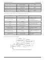
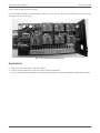
1
NXRTi-DRY
Dry Contact Card
User’s Manual
www.xpcc.com | © 2015 Xtreme Power Conversion Corporation. All rights reserved. (Rev 2/12/15)
NXRTi-DRY User’s Manual
Dry Contact Card
Thank you for selecting this uninterruptible power supply (UPS) option. The UPS provides you with protection
for connected equipment. This Dry Contact Card option provides optional communication hardware for the UPS.
Please read this manual and the UPS User’s Manual before installing the NXRTi-DRY Contact Card into the Series
UPS models NXRTi-1000, NXRTi-2000 and NXRTi-3000 as it provides important information that should be followed
during installation and maintenance of the UPS and batteries, allowing you to correctly set up your system for the
maximum safety and performance. Included is information on customer support and service, if it is required. If
you experience a problem with the UPS, please refer to the Troubleshooting section in this manual to correct the
problem. If the problem is not corrected, please collect information so that the Technical Support personnel can
more effectively assist you.
WARNING: Any changes or modifications not expressly approved by the manufacturer of this device could void the
user’s authority to operate the equipment.
Important Safety Instructions: (Save These Instructions)
CAUTION! (UPS having Internal Batteries): Risk of electrical shock – Hazardous live parts inside this unit are energized from the battery supply even when the input AC power is disconnected.
CAUTION! (No User serviceable Parts): Risk of electrical shock, do not remove cover. No user serviceable parts
inside. Refer servicing to qualified service personnel.
CAUTION! (Non-isolated Battery supply): Risk of electric shock, battery circuit is not isolated from AC input, hazardous voltage may exist between battery terminals and ground. Test before touching.
WARNING! (Fuses): To reduce the risk of fire, replace only with the same type and size of fuse.
WARNING! Unit intended for installation in a controlled environment.
CAUTION! Do not dispose of batteries in a fire, the battery may explode.
CAUTION! Do not open or mutilate the battery, released electrolyte is harmful to the skin and eyes.
CAUTION! A battery can present a risk of electric shock and high short circuit current. The following precaution
should be observed when working on batteries:
• Remove watches, rings or other metal objects.
• Use tools with insulated handles.
To reduce the risk of electric shock, disconnect the UPS from the main supply before installing a computer interface signal cable. Reconnect the power cord only after signaling interconnections have been made.
Servicing of batteries should be performed or supervised by personnel with knowledge of batteries and the required precautions. Keep unauthorized personnel away from batteries.
These UPS units are extremely heavy. Do not install the UPS in a rack or enclosure by its front two ears only. Adjustable rack rails are required for this type of installation.
The instructions contained within this safety manual are deemed important and should be closely followed at all
times during installation and follow-up maintenance of the UPS and batteries.
Xtreme Power Conversion Corporation
Page 2
NXRTi-DRY User’s Manual
Dry Contact Card
CAUTION
The unit has a dangerous amount of voltage. If the UPS indicator is on, the unit’s outlets may have a
dangerous amount of voltage even when not plugged into the wall outlet because the battery may continue to supply power.
Care should be taken to undertake installation indoors, free from electrically-conductive particles which
are under temperature and humidity control, in order to reduce the risk of electric shock.
It is best to disconnect the device using the power supply cord. Ensure that the equipment is placed in
a position near the outlet where easily accessible.
Except for replacing the batteries, all servicing on this equipment must be carried out by qualified service personnel.
Before conducting any maintenance, repair, or shipment, first ensure that everything is turned off completely and disconnected.
For additional safety instructions, please use the Safety Manual as a reference.
Special Symbols
The following symbols used on the UPS warn you of precautions:
Xtreme Power Conversion Corporation
Page 3
NXRTi-DRY User’s Manual
Dry Contact Card
EMC Standard/Safety Standard
Our products are manufactured in accordance with the following EMC international grade standards and has
passed the CE authentication:
EMC standard number
IEC62040-2
IEC61000-4-2
IEC61000-4-3
IEC61000-4-4
IEC61000-4-5
Safety standard number
IEC62040-1
GB4943-2005
Introduction
The information provided in this manual covers installation of the optional Dry Contact Card into the high-voltage,
single phase 1000-3000 VA uninterruptible power systems. Electrical installation must also carefully follow local
legislation and regulations. Only qualified personnel should conduct these installations as failure to acknowledge
electrical hazards could prove to be fatal.
Functional Description
The Dry Contact Card is a UPS option which is used to provide UPS internal status to the outside, or control peripheral devices in accordance with the UPS status, in the form of dry contacts. The Dry Contact Card is inserted into
the INTELLIGENT SLOT which is also the SNMP slot in the rear of the UPS. (Fig 1)
Fig. 1 – Dry Contact Card installation into SNMP Slot
The Dry Contact Card DB-9 Interface assignments are show in Fig. 2
DB-9 Pin Number
1
2
3
Xtreme Power Conversion Corporation
Functional Description
UPS Failure
UPS Summary Alarm
Ground
Input / Output
Output
Output
Page 4
NXRTi-DRY User’s Manual
4
5
6
7
8
9
Dry Contact Card
Remote Shutdown
Common Source
Bypass Active
Battery Low
UPS ON
Utility Failure
Fig. 2 – Dry Contact Card DB-9 Interface Assignments
Input
Output
Output
Output
Output
The Dry Contact Card DB-9 Interface function descriptions are show in Fig. 3
Function
PIN 1, PIN 5 ON
Functional Description
UPS Failure
PIN 2, PIN 5 ON
UPS Summary Alarm
PIN 3
Ground
PIN 4
Remote Shutdown
PIN 5
PIN 6, PIN 5 ON
PIN 6, PIN 5 OFF
PIN 7,PIN 5 ON
Common Source
Bypass Active
UPS ON
BATTERY LOW
PIN 8, PIN 5 ON
PIN 8, PIN 5 OFF
PIN 9, PIN 5 ON
Reason
UPS INTERAL FAILURE
1. UPS IS ON BATTERY
2. BATTERY LOW
3. UPS INTERNAL FAILURE
THIS IS THE OUTSIDE INPUT REMOTE SHUTDOWN SIGNAL
BYPASS IS POWERING THE LOAD
UTILITY INVERTER MODE
BATTERY LOW
UPS INVERTER POWERING THE
UPS ON
LOAD
BYPASS ACTIVE
BYPASS POWERS THE LOAD
UTILITY FAILURE
UTILITY FAILURE
Fig. 3 – Dry Contact Card DB-9 Function Description
Fig. 4 shows the DB-9 internal interface route
Fig. 4 – Dry Contact Card DB-9 Internal Interface Route
Xtreme Power Conversion Corporation
Page 5
NXRTi-DRY User’s Manual
Dry Contact Card
Fig. 5 shows the DB-9 internal electrical parameters
PARAMETER
DIODE
SYMBOL
MAX
REVERSE VOLTAGE
VR
6
FORWARD CURRENT IF
80
PEAK FORWARD
IF(PEAK)
1
CURRENT
DC VOLTAGE
VDC
28
DC CURRENT
IDC
7.0
AC VOLTAGE
VAC
125 250
AC CURRENT
IAC
12 7
Fig. 5 – Dry Contact Card DB-9 Internal Electrical Parameters
UNIT
VOLTS
MILLI-AMPS
AMPS
VOLTS
AMPS
VOLTS
AMPS
Fig. 6 shows the Application Instructions of the Dry Contact Card
Fig. 6 – Dry Contact Card Application Instructions
Fig. 7 shows the Pin Definitions of the Connecting Terminals on the Dry Contact Card
NC = NORMALLY CLOSED; NO = NORMALLY OPEN
TERMINAL NUMBER
1
2
3
4
5
6
7
8
TERMINAL FUNCTION
UPS FAILURE NC
UPS FAILURE NO
BYPASS STATUS NC
BYPASS STATUS NO
TERMINAL NUMBER
9
10
11
12
TERMINAL FUNCTION
INVERTER ON NC
INVERTER ON NO
UTILITY FAILURE NC
UTILITY FAILURE NO
OPERATION INDICATION
UPS ALARM NC
13
NC
OPERATION INDICATION
UPS ALARM NO
14
NO
BATTERY LOW NC
15
COMMON SOURCE
BATTERY LOW NO
16
COMMON SOURCE
Fig. 7 – Pin Definitions for Connecting Terminals on the Dry Contact Card
For the function of connecting terminals on the board, please refer to the DB-9 interface pin instructions. The wire
connecting is also similar to the DB-9. It also provides normally open contact (even terminal pin) besides the norXtreme Power Conversion Corporation
Page 6
NXRTi-DRY User’s Manual
Dry Contact Card
mally closed contact (odd terminal pin).
For the function definition of connecting terminals, you can also get relevant information from the silk-screen
printing on the rear of the card.
Fig. 8 – Dry Contact Card physical view
Applications
1. IBM server, PC, work station, and other devices
2. Industry device automatic control and communication applications
3. The Dry Contact Card only provides an interface (dry contact), users are responsible for application software
Xtreme Power Conversion Corporation
Page 7
NXRTi-DRY User’s Manual
Dry Contact Card
Installation
1. Open the cover plate for the SNMP slot on the rear panel of the NXRTi or NXRTg Series UPS.
Fig. 9 – Dry Contact Card installation - rear view
2. Insert the Dry Contact Card (NXRTi-DRY) directly along the gap of SNMP slot.
3. Insert the Dry Contact Card (NXRTi-DRY) until the metal plate of DB-9 interface is flush with the rear surface of
the UPS. Attach the screws to secure the Dry Contact Card in place.
Xtreme Power Conversion Corporation
Page 8
NXRTi-DRY User’s Manual
Dry Contact Card
Obtaining Service
If the UPS requires Service:
1. Use the TROUBLESHOOTING section in this manual to eliminate obvious causes.
2. Verify there are no circuit breakers tripped.
3. Call your dealer for assistance. If you cannot reach your dealer, or if they cannot resolve the problem, call Xtreme
Power Conversion Corp Technical Support at 800.582.4524. Technical support inquiries can also be made at
[email protected]. Please have the following information available BEFORE calling the Technical Support
Department:
• Your name and address.
• The serial number of the unit.
• Where and when the unit was purchased.
• All of the model information about your UPS.
• Any information on the failure, including LED’s that may or may not be illuminated.
• A description of the protected equipment, including model numbers if possible.
• A technician will ask you for the above information and, if possible, help solve your problem over the
phone. In the event that the unit requires factory service, the technician will issue you a Return Material Authorization number (RMA).
If you are returning the UPS to Xtreme Power for service, please follow these procedures:
1. Pack the UPS in its original packaging. If the original packaging is no longer available, ask the Technical Support Technician about obtaining a replacement set of packaging material. It is important to pack the UPS
properly in order to avoid damage in transit. Never use Styrofoam beads for a packing material.
2. Include a letter with your name, address, daytime phone number, RMA number, a copy of your original
sales receipt, and a brief description of the problem.
3. Mark the RMA number on the outside of all packages. Xtreme Power cannot accept any package without
the RMA number marked on the outside of the boxes.
4. Return the UPS by insured, prepaid carrier to the address provided by the Technician.
5. Refer to the Warranty statements in this manual for additional details on what is covered.
Xtreme Power Conversion Corporation
Page 9
NXRTi-DRY User’s Manual
Xtreme Power Conversion Corporation
Dry Contact Card
Page 10
NXRTi-DRY User’s Manual
Xtreme Power Conversion Corporation
Dry Contact Card
Page 11