1
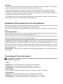
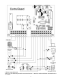
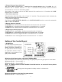
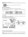
www.WholesaleGateOpener.com
Rev 11a
Table of Contents
General Safety ………………………………………..…………………………………......………………….. 2
Important Safety Instructions ………………………………………..…………………………………........… 3
Preparation for Installation ………………………………………..…………………………………......…….. 5
Parts List ………………………………………..…………………………………......…………………………. 6
Technical Specifications & Feature ………………………………………..………………………………….... 7
Installation Overview ………………………………………..…………………………………......……………. 8
Installation of the Opener ……………………………………..…………………………………...... ………. 8
Manual Operation ………………………………………..…………………………………......……………….. 9
Fit The Rack ………………………………………..…………………………………......…………………… 9
Installation of the Limit Switch ………………………………………..…………………………………......... 11
Connecting of the Control Board …………………………………………..……………………………………. 11
Setting of the Control Board …………………………………………..…………………………………......….. 13
Test the reversing sensitivity ……………………………………………………………………….................... 14
How to learn or erase the remote ………………………………….………..……………………………… 15
How to use the remote to control the operator ………………………………………..……………………… 15
Trouble Shooting ………………………………………..…………………………………......………………. 15
Maintenance ………………………………………..……………………………………………………………… 16
1
Thank you for purchasing SFG18 /21H sliding gate opener. We are sure that the products will be greatly
satisfying as soon as you start to use it.
The product is supplied with a user’s manual which encloses installation and safety precautions. These
should be read carefully before installation and operation as they provide important information about safety,
installation, operation and maintenance. This product complies with the recognized technical standards and
safety regulations.
General Safety
WARNING! An incorrect installation or improper use of the product can cause damage to persons,
animals or properties.
• Scrap packing materials (plastic, cardboard, polystyrene etc.) according to the provisions set out by current
standards. Keep nylon or polystyrene bags out of children’s reach.
• This product was exclusively designed and manufactured for the use specified in the present
documentation. Any other use not specified in this documentation could damage the product and be
dangerous.
• The factory declines all responsibility for any consequences resulting from improper use of the product, or
use which is different from that expected and specified in the present documentation.
• Do not install the product in explosive atmosphere.
• The factory declines all responsibility for any consequences resulting from failure to observe Good
Technical Practice when constructing closing structures (door, gates etc.), as well as from any deformation
which might occur during use.
• Disconnect the electrical power supply before carrying out any work on the installation. Also disconnect
any buffer batteries, if fitted.
• Fit an omnipolar or magnetothermal switch on the mains power supply, having a contact opening distance
equal to or greater than 3,5 mm.
• Check that a differential switch with a 0.03A threshold is fitted just before the power supply mains.
• Check that earthing is carried out correctly: connect all metal parts for closure (doors, gates etc.) and all
system components provided with an earth terminal.
• Fit all the safety devices (photocells, electric edges etc.) which are needed to protect the area from any
danger caused by squashing, conveying and shearing.
• Position at least one luminous signal indication device (blinker) where it can be easily seen, and fix a
Warning sign to the structure.
• The factory declines all responsibility with respect to the automation safety and correct operation when
other supplier’s components are used.
• Only use original parts for any maintenance or repair operation.
• Do not modify the automation components, unless explicitly authorized by the factory.
• Instruct the product user about the control systems provided and the manual opening operation in case of
emergency.
• Do not allow persons or children to remain in the automation operation area.
• Keep radio control or other control devices out of children’s reach, in order to avoid unintentional
automation activation.
• The user must avoid any attempt to carry out work or repair on the automation system, and always request
the assistance of qualified personnel.
• Anything which is not expressly provided for in the present instructions is not allowed.
• Installation must be carried out using the safety devices and controls prescribed by the EN 12978
Standard.
2
Important Safety Instructions
WARNING – To reduce the risk of injury or death:
1) READ AND FOLLOW ALL INSTRUCTIONS.
2) Never let children operate or play with gate controls. Keep the remote control away from children.
3) Always keep people and objects away from the gate. NO PERSON SHOULD CROSS THE PATH OF
THE MOVING GATE.
4) Test the gate opener monthly. The gate MUST reverse on contact with a rigid object or stop when an
object activates the non-contact sensors. After adjusting the force or the limit of travel, retest the gate opener.
Failure to adjust and retest the gate opener properly can increase the risk of injury or death.
5) Use the emergency release only when the gate is not moving.
6) KEEP GATES PROPERLY MAINTAINED. Read the owner’s manual. Have a qualified service person
make repairs to gate hardware.
7) The entrance is for vehicles only. Pedestrians must use separate entrance.
8) SAVE THESE INSTRUCTIONS.
Safety Instructions for Installation
A. Install the gate opener only when:
1) The opener is appropriate for the construction of the gate and the usage Class of the gate,
2) All openings of a horizontal slide gate are guarded or screened from the bottom of the gate to a minimum
of 4 feet (1.22 m) above the ground to prevent a 2-1/4 inch (57.2 mm) diameter sphere from passing through
the openings anywhere in the gate, and in that portion of the adjacent fence that the gate covers in the open
position,
3) All exposed pinch points are eliminated or guarded.
4) Guarding is supplied for exposed rollers.
B. The opener is intended for installation only on gates used for vehicles. Pedestrians must be supplied with
a separate access opening. The pedestrian access opening shall be designed to promote pedestrian usage.
Locate the gate such that persons will not come in contact with the vehicular gate during the entire path of
travel of the vehicular gate.
C. The gate must be installed in a location so that enough clearance is supplied between the gate and
adjacent structures when opening and closing to reduce the risk of entrapment.
D. The gate must be properly installed and work freely in both directions prior to the installation of the gate
opener. Do not over-tighten the opener clutch or pressure relief valve to compensate for a damaged gate.
E. For gate openers utilizing Type D protection:
1) The gate opener controls must be placed so that the user has full view of the gate area when the gate is
moving.
2) The placard provided marked in letters at least 1/4-in (6.4-mm) high with the word ″WARNING″ and the
following statement or the equivalent: “ Moving Gate Has the Potential of Inflicting Injury or Death – Do Not
Start Gate Unless Path is Clear” shall be placed adjacent to the controls,
3) An automatic closing device (such as a timer, loop sensor, or similar device) shall not be employed.
4) No other activation device shall be connected.
F. Controls intended for user activation must be located at least ten feet (10’) away from any moving part of
the gate and where the user is prevented from reaching over, under, around or through the gate to operate
the controls. Outdoor or easily accessible controls shall have a security feature to prevent unauthorized use.
3
G. The Stop and/or Reset button must be located in the line-of-sight of the gate. Activation of the reset
control shall not cause the opener to start.
H. A minimum of two (2) WARNING SIGNS shall be installed, one on each side of the gate where easily
visible.
I. For a gate opener utilizing a non-contact sensor in accordance Usage Class:
1) See instructions on the placement of non-contact sensors for each Type of application,
2) Care shall be exercised to reduce the risk of nuisance tripping, such as when a vehicle trips the sensor
while the gate is still moving, and in the opening direction.
3) One or more non-contact sensors shall be located where the risk of entrapment or obstruction exists,
such as the perimeter reachable by a moving gate or barrier.
J. For a gate opener utilizing a contact sensor in accordance with Usage Class:
1) One or more contact sensors shall be located where the risk of entrapment or obstruction exists, such as
at the leading edge, trailing edge, and post-mounted both inside and outside of a vehicular horizontal slide
gate.
2) One or more contact sensors shall be located at the bottom edge of a vehicular vertical lift gate.
3) One or more contact sensors shall be located at the pinch point of a vehicular vertical pivot gate.
4) A hardwired contact sensor shall be located and its wiring arranged so that the communication between
the sensor and the gate opener is not subjected to mechanical damage.
5) A wireless contact sensor such as one that transmits radio frequency (RF) signals to the gate opener for
entrapment protection functions shall be located where the transmission of the signals are not obstructed or
impeded by building structures, natural landscaping or similar obstruction. A wireless contact sensor shall
function under the intended end-use conditions.
6) One or more contact sensors shall be located on the inside and outside leading edge of a sliding gate.
Additionally, if the bottom edge of a sliding gate is greater than 6 inches (152 mm) above the ground at any
point in its arc of travel, one or more contact sensors shall be located on the bottom edge.
7) One or more contact sensors shall be located at the bottom edge of a vertical barrier (arm).
4
Preparation for Installation
Before proceeding to your opener installation, check if your gate structure is in accordance with the current
standards, especially as follows:
The gate sliding track is linear and horizontal, and the wheels are suitable,the gate should be mounted and
moving freely. Check that the structure is sufficiently strong and rigid, and that its dimensions and weights
conform to those listed in the specifications table of this document. Make sure that the gate is plumb and
level. The fence posts must be mounted in concrete. The gate does not bind or drag on the ground.
• The gate manual operation can be carried out smoothly along its entire run, and there is no excessive side
slipping.
• The opening and closing gate stops are positioned.
WARNING: Remember that control devices are intended to facilitate gate operation, but can not
solve problems due to any defects or deficiency resulting from failure to carry out correct installation or
maintenance. Take the product out of its packing and inspect it for damage. Should it be damaged, contact
your dealer. Remember to dispose of its components (cardboard, polystyrene, nylon, etc.) according to the
current prescriptions.
Refer to the following Figures for gate installation.
Using the post or wall as a stop, either directly or indirectly, is not
recommended so as to protect the post or wall against damaging shock
from the sliding gate.
In sake of safety, a positive stop must be mounted on the two end of ground track.
5
It is suggestion that there is a 4”(10cm) distance at least between the gate edge and the gate wall
when the gate is fully open.
Parts List
6
Technical Specifications & Features
Specifications
·Power supply: 120V/60HZ or 230V/50HZ
·Motor: 120VAC or 230VAC
·Absorbed power: SFG18:370W / SFG21:550W
·Gate moving speed: (7.9“/second) 20 cm/second
·Max gate weight: SFG18:800KGS / SFG21:1200KGS
·Max torque: SFG18: 24Nm / SFG21: 35Nm
·Environmental conditions: from -15°C to +40°C
·Protection class:
IP44
·Dimensions: 38×28×36 CM
·Class of gate opener: I, II
Features:
·Easy to install and low maintain.
·Midway mode
·Quick selection for gate open/close direction
·Reliable rolling code technology
·Emergency release key in case of power failure
·Stop/Reverse in case of obstruction during gate opening/closing.
·Built in adjustable auto-close (5-100 seconds)
·Built in max. Motor running time (MRT) adjustable for multiple safety protection (5-100 seconds)
·Reliable electromagnetism limit for easy adjustment
·Can be equipped with wide range accessories
7
Installation Overview
Installation of the Opener
Caution:
*Be sure that the opener is installed in a level and paralleled position and is properly secured.
Improper installation could result in property damage, severe injury, and/or death.
* Before starting installation, ensure that there is no point of friction during the entire movement of
the gate and there is no danger of derailment.
* Ensure that the safety side panels are present.
Necessary Tools: The following tools
may be necessary to install the Gate
opener. You will need screwdrivers, an
electric drill, wire cutters and a wire
stripper, a socket set, and possibly
access to a welder.
When install the opener, you should
build a concrete pad to support the base
plate of opener in order to maintain
proper stability.
The installation proceeds are as
follows:
1.Dig a hole for a concrete pad which
should be approximately 50 x 30 x 35cm
(20〞x 12〞x 14〞). It may protrude 10
cm (4”) above ground and 25 cm (10”) in
depth underground. Increase the pad
height if necessary to protect the system
from flooding, heavy snow etc.
2. Prepare one or more conduits for the
electrical cables before pour concrete.
Remember that cable conduits have to
pass through the hole in the base plate.
8
3. Pour concrete and before it starts to harden, check that it is parallel to the gate leaf and perfectly level.
4. Mark the position of four expansion anchors according to the position of mounting hole on the base plate
as soon as concrete become harden. Double check your marking, move the base plate and drill the 4 holes
using a 10mm (3/8”) masonry bit. Put the 4 expansion anchors (provided) into the holes and firmly tighten.
5. Place the opener onto base plate. Check that it is perfectly parallel to the gate leaf, and then screw the
four nuts and washers supplied. It's only temporary installation. Further adjustment will be required when
install the rack or chain.
Manual Operation
The opener should be put in the manual (emergency release) position before fitting the rack, installing the
opener and limit switch. The process is as follows:
1) Insert and turn the key clockwise 45° to slide the lock cover. Now the key slot appears.
2) Insert the T-handle Key(provided)to the key slot and turn it in counter-clockwise 135° to disengage the
clutch between the gear shaft and power output. Now the opener is in the manual operation.
Fit the Rack
There are two kinds of rack available as per buyer’s option, which are steel reinforced plastic rack and
galvanized steel rack. The galvanized steel rack is usually used for the heavy duty gate.
A. Fit the plastic rack reinforced with steel
1. Start with gate in closed position
2. There are four sections of plastic rack which is one meter length, each section for standard package. (you
can order extra rack from dealer if necessary)
2. Put one end of rack section on the gear of opener as a temporary support.
Make rack level and mark the rack’s mounting holes (four holes) on the gate.
3. Fit the rack by self-threading screws. This kind of plastic rack is quieter and allows height adjustments to
be made even after it has been fixed. Please keep 1.0mm space between the rack and the gear to avoid the
weight of the gate leaf effect on the opener.
9
B. Fit the galvanized steel rack
1. Start with gate in closed position
2. There are four sections of steel rack which is one meter length, each section for standard package. (you
can order extra rack from dealer if necessary)
2. Put one end of rack section on the gear of opener as a temporary support.
Make rack level and mark the rack’s mounting holes (three holes) on the gate.
3. Weld the rack nut on the gate as mark and connect the rack to the gate using the bolt provided. Before
weld, please keep 1.0mm space between the rack and the gear to avoid the weight of the gate leaf effect on
the opener.
10
Important:
* Check that the rack teeth must engage the gear teeth throughout their full thickness. If not, adjust the
position of the opener or/and place a few shims between the rack and gate.
4. Manually slide the gate leaf to ensure the rack is proper on the gear of opener, weld the second nut.
5. Repeat same steps of first rack section to install the rest rack sections until proper length is reached.
6. Cut away any excess of the rack (Note: rack length must be longer than actual travel of the gate to
accommodate limit switch brackets on each gate side.)
7. Thoroughly fasten the four nuts as well as spring washers onto expansion bolt tightly, enabling the opener
is firmly secured on the concrete pad during the whole gate travel.
Installation of the magnets for the Limit Switches
Before install limit switch, make sure the gate opener is put in manual operation. (the clutch connected with
gear shaft is disengaged) and the mains power supply is disconnected.
Position the two limit stop brackets approximately on the rack and move the gate by hand to fix them in
place.
Fit magnets bracket
Push the gate fully closed by hand. Locate and install the magnet bracket so that the opener will stop at the
desired close position when the close limit switch approaches it.
Push the gate fully open by hand. Locate and install the magnet bracket so that the opener will stop at the
desired open position when the open limit switch approaches it.
The higher magnet bracket must be installed at left side and lower magnet bracket must be installed
at right side from the view inside of property. Finally adjust the magnet to the proper position by moving
the gate with the motor. The magnet should be 39 - 59 “away from the magnetic limit switch. If it is too far
away, the switch will fail to work. The distance between the magnet and the opener should be 1/2” (12mm)
with the opener cover on. Adjust the position of the magnet until the positions of the opening and closing
meet the requirement.
Important Note: Please note the two magnet brackets (fixed plate) are different: one is higher and ano the
other is lower.
Connecting of the control board
Warning:Before making any electrical wire connection or/and setting the control board, make sure
that the power switch is OFF.
1. Motor
The BLACK wire of the motor should be connected into the “6” terminal.
The RED wire of the motor should be connected into the “7” terminal.
The YELLOW wire of the motor should be connected into the “8” terminal.
2. Start Capacitor
One pin of the start capacitor should be wired to the “7” terminal, another to “8” terminal.
3. Limit Switches
The RED wire of the limit switches should be connected into the “9” terminal.
The BLACK wire of the limit switches should be connected into the “10” terminal.
The YELLOW wire of the limit switches should be connected into the “11” terminal.
11
4. Alarm Lamp (Optional)
One wire of the alarm lamp should be connected into the “4” terminal, another should be connected into the
“5” terminal.
12
5. Photocell (Normal Open) (Optional)
Use a 2-core cable to connect the “+ ~” terminal of the photocell’s emitter to the “12” terminal, the “- ~”
terminal to the “13” terminal. Also the “+ ~” and “- ~” terminals of the photocell’s receiver should be
connected to the “12” and “13” terminals in parallel.
Use another 2-core cable to connect the “NO” terminal of the receiver to the “14” terminal, the “COM”
terminal to the “15” terminal.
6. Push Button (Optional)
The push button should be wired to the “15” and “16” terminals. The gate operator works alternately by
pushing the button (open-stop-close-stop-open).
7. Loop Detector (Optional)
First insert the LOOP DETECTOR BOARD into the CONTROL BOARD, and then connect the twisted-pair
to the “17” and “18” terminals.
8. External Receiver (Optional)
The BROWN wire of the external receiver should be connected into the “16” terminal.
The BLACK wire of the external receiver should be connected into the “13” terminal.
The RED wire of the external receiver should be connected into the “12” terminal.
9. Wired Keypad (12VDC) (Optional)
The RED wire of the wired keypad should be connected into the “12” terminal.
The BLACK wire of the wired keypad should be connected into the “13” terminal.
The WHITE wire of the wired keypad should be connected into the “16” terminal.
The BLUE wire of the wired keypad should be connected into the “15” terminal.
Setting of the Control Board
1. DIP Switches
The DIP switches are used to set
the running time of the motor in
midway mode, auto close time of
the gate operator and fast change
the open/close direction which is
determined by the position of the
gate operator installed.
DIP Switch #1–#2: Running time of the motor in Midway Mode
This mode enables user to drive the vehicle through the gate quickly when the gate opens to certain width.
DIP Switch #1: ON – 2 Seconds OFF – 0
DIP Switch #2: ON – 4 Seconds OFF – 0
NOTE: The midway function would be disabled if both DIP switches are turned off. Factory default
setting is disabled.
E.g.
Running time of the operator in midway mode is 2+4=6 seconds.
DIP Switch #3–#4: Auto close time of the gate operator
DIP Switch #3: ON – 30 Seconds OFF – 0
13
DIP Switch #4: ON – 60 Seconds OFF – 0
NOTE: The auto close function would be disabled if both dip switches are turned to off (factory
default setting).
E.g.
Auto close time of the gate operator is 30+60=90 seconds.
DIP Switch #5: Left/Right open
ON – Left open (factory default setting).
OFF – Right open. Turn switch OFF to change the opening direction easy if necessary.
2. Potentiometers
The potentiometer A is to adjust the OPEN stall force of the gate operator. The Potentiometer B is used to
adjust the CLOSE stall force of the gate operator.
Turn the potentiometer clockwise to increase the stall force.
Turn the potentiometer counter-clockwise to decrease the stall force.
Test the reversing sensitivity
For the sake of safety, it is very important to test the reversing sensitivity as soon as the control board set is
finished.
The reversing sensitivity adjustment is inverse correlation with stall force adjustment in potentiometer A
and potentiometer B. In other word, the stall force level is higher; the reversing sensitivity level is lower.
14
Put an immobile object along the gate path, and then operate the gate to strike it during the open and close
cycles. The gate must reverse as soon as object is struck with it. If the gate doesn’t reverse, please increase
the reversing sensitivity by turning the potentiometer in counter-clockwise direction. (Turning the stall force
potentiometer toward to MIN position to increase the reversing sensitivity)
Note 1: If the sensitivity setting is too higher, the gate will stop or reverses very easy by itself while
there is little obstruction or resistance such as strong wind or heavy snow sometimes.
Note 2: Always check the gate reversing function every each time of control board set or restart after
power off.
How to learn or erase the remote
Learn the remote
Press and release the learn button, the REM LED
light will be on, then press the key in the
remote twice in 2 seconds, the REM LED
light will flash for 4 seconds. Now the
remote has been learnt successfully.
Erase all the remote codes
Press and hold the learn button until the REM LED light is off. Now all remote codes have been erased.
How to use the remote to control the operator
Key A is used to operate the operator to work alternately (open-stop-closestop-open).
When the Midway Mode function is enabled, Key B is used to achieve the
Midway Mode function (open the gate for the pre-setting time). When the
Midway Mode function is disabled, the operator works alternately (open-stop
-close-stop-open) by pressing Key B.
Troubleshooting
Have a multimeter to check voltage and continuity. Use caution when checking high voltage terminals.
1. Motor only runs toward one direction.
a. The limit switch is failed. Disconnect the limit switches and try it again.
b. The start capacitor of the motor is failed. Replace the capacitor.
c. The electric component on the control board may be damaged. Replace the electric component or replace
the control board.
2. The gate does not open or close.
a. The power switch is OFF. Make sure the power switch is ON.
b. The limit switches are failed. Disconnect the limit switches and try it again.
c. Connecting wires or terminal blocks are too loose. Check the connecting wires and terminal blocks.
d. The motor has been damaged. Replace the motor if necessary.
e. The thermal protector is working because the high temperature after long working time. Please wait for 20
minutes to let the motor become cold.
15
f. The electric component on the control board has been damaged. Replace the electric component or
replace the control board.
3. Remote control does not work.
a. The distance you use the remote is too far away from the opener. Try it again closer.
b. Remote control is not suitable for receiver. After making sure the codes are correct, erase remote controls
and then re-program the codes in the device.
c. Broken receive board. Replace receive board.
d. The indicator light of remote control is not on. Check the battery in your remote control. Replace the
battery if necessary.
4. When you open or close the gate by pressing key #1 and key #2 which have been programmed,
gate will stop in mid-travel or reverse before reaching the fully limit position.
a. The opening force or closing force is adjusted too small. Turn the Potentiometer 1 and 2 to increase the
force.
b. Gate is obstructed. Remove the obstruction.
5. The gate opens, but stops and will not return.
a. Please note the two magnet brackets (fixed plate) are different: one is higher and another is lower. Please
try to exchange the two brackets position.
b. Please try to exchange the limit switch wires CL (close) and OP (open). There are two reed switches
inside the magnetic limit switch: one is upper and another is lower. Maybe the magnet position was installed
in the middle so it inducts both switches. Adjust the magnet upper or lower.
6. The gate can open, but fails to close.
a. Photocell is obstructed. Remove obstruction.
b. The limit switch is failed. Disconnect the limit switches and try it again.
c. The start capacitor of the motor is failed. Replace the capacitor.
d. The electric component on the control board has been damaged. Replace the electric component or
replace the control board.
7.The motor runs but the gate doesn’t move.
The clutch for emergency release is adjusted properly and is not slipping.
Maintenance
Every six months check the following items for proper operation of the unit.
* Lubricate shafts and sprockets.
* Keep operator clean at all times.
* Check and tighten anchors bolts.
* Check for loose or corroded wire
* Ensure the operator is well earthed, and correctly terminated.
* Always check the Stop/Reverse in case of obstruction function when performing any maintenance. If this
function can’t be made operable, remove this operator from service until the cause of the malfunction is
identified and corrected.
16
www.WholesaleGateOpener.com
7106 S 220th St, Kent WA 98032 USA
[email protected]
©2010-2012 LockMaster All Rights Reserved