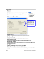
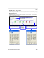
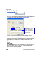
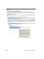
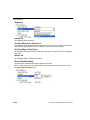
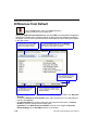
1
QX Hawk Industrial Imager
User’s Manual
P/N 83-006800 Rev D
Copyright and Disclaimer
Copyright ©2011
Microscan Systems, Inc.
ISO 9001 Certified
Issued by TüV USA
All rights reserved. The information contained herein is proprietary and is provided solely for the purpose
of allowing customers to operate and/or service Microscan manufactured equipment and is not to be
released, reproduced, or used for any other purpose without written permission of Microscan.
Throughout this manual, trademarked names might be used. Rather than place a trademark (™) symbol
at every occurrence of a trademarked name, we state herein that we are using the names only in an editorial
fashion, and to the benefit of the trademark owner, with no intention of infringement.
Disclaimer
The information and specifications described in this manual are subject to change without notice.
Latest Manual Version
For the latest version of this manual, see the Download Center on our web site at:
www.microscan.com.
Technical Support
For technical support, e-mail: [email protected].
Warranty and Terms of Sale
For Standard Warranty information, see: www.microscan.com/warranty.
Microscan Systems, Inc.
Renton Headquarters
425.226.5700 / 800.251.7711
Nashua Office
603.598.8400
Microscan Europe
011 31 172 423360
Microscan Asia Pacific
65 6846 1214
ii
QX Hawk Industrial Imager User’s Manual
Introduction
Table of Contents
Chapter 1
Quick Start
Step 1 Check Hardware .......................................................................... 1-2
Step 2 Connect the System ..................................................................... 1-3
Step 3 Position the Imager ...................................................................... 1-4
Step 4 Install ESP.................................................................................... 1-5
Step 5 Select Model ................................................................................ 1-6
Step 6 Connect ........................................................................................ 1-7
Step 7 Locate Symbol ............................................................................. 1-9
Step 8 Calibrate..................................................................................... 1-11
Step 9 Test Read Rate .......................................................................... 1-12
Step 10 Configure the Imager ............................................................... 1-13
Step 11 Save Changes.......................................................................... 1-14
Chapter 2
Using ESP
EZ Mode .................................................................................................. 2-2
App Mode ................................................................................................ 2-3
Menu Toolbar .......................................................................................... 2-4
Navigating in ESP................................................................................. 2-15
Send/Receive Options .......................................................................... 2-16
Chapter 3
Hardware Integration
Connectors .............................................................................................. 3-2
Cordsets .................................................................................................. 3-3
QX Hawk and QX-1 Connectors and Pinouts.......................................... 3-4
Power and Trigger Switching................................................................... 3-8
Port Routing............................................................................................. 3-9
Application Examples ............................................................................ 3-10
Chapter 4
Setup
Video ....................................................................................................... 4-2
Evaluation ............................................................................................. 4-14
Calibration ............................................................................................. 4-17
Window of Interest ................................................................................. 4-18
Configuration Database ......................................................................... 4-20
Ordered Output...................................................................................... 4-27
Output Format ....................................................................................... 4-31
Dynamic Setup ...................................................................................... 4-35
Chapter 5
Parameters
Communication........................................................................................ 5-2
Read Cycle ............................................................................................ 5-40
Symbologies .......................................................................................... 5-60
I/O Parameters ...................................................................................... 5-97
Symbol Quality .................................................................................... 5-159
Matchcode ........................................................................................... 5-166
QX Hawk Industrial Imager User’s Manual
iii
Table of Contents
Diagnostics .......................................................................................... 5-175
Chapter 6
Terminal
Terminal Window..................................................................................... 6-2
Find ......................................................................................................... 6-3
Send ........................................................................................................ 6-4
Macros..................................................................................................... 6-5
Terminal Window Menus ......................................................................... 6-6
Chapter 7
Utilities
Serial Utility Commands .......................................................................... 7-2
Read Rate ............................................................................................... 7-4
Counters .................................................................................................. 7-6
Device Control ......................................................................................... 7-9
Differences from Default........................................................................ 7-10
Master Database ................................................................................... 7-11
Firmware ............................................................................................... 7-17
Bar Code Configuration Mode ............................................................... 7-21
Calibration ............................................................................................. 7-22
Default/Reset/Save ............................................................................... 7-23
Imager Status ........................................................................................ 7-25
Learn Operations................................................................................... 7-27
Reboot System ...................................................................................... 7-28
Static Validation..................................................................................... 7-29
Targeting ............................................................................................... 7-31
Y-Modem Transfer Options ................................................................... 7-32
Appendices
Appendix A General Specifications .........................................................A-2
Appendix B Electrical Specifications .......................................................A-8
Appendix C Ground and Shield Considerations ....................................A-16
Appendix D Flying Lead Cordset Pinouts..............................................A-18
Appendix E Serial Commands ..............................................................A-19
Appendix F Protocol Commands...........................................................A-72
Appendix G ASCII Table .......................................................................A-81
Appendix H Configuring Ethernet TCP/IP .............................................A-82
Appendix I Using EtherNet/IP................................................................A-85
Appendix J Allen-Bradley PLC Setup ....................................................A-94
Appendix K Interface Standards..........................................................A-113
Appendix L Glossary of Terms ............................................................A-114
iv
QX Hawk Industrial Imager User’s Manual
Introduction
About the QX Hawk Industrial Imager
The key features of the QX Hawk Industrial Imager are:
•
•
•
•
•
•
•
•
•
•
Fully integrated liquid lens technology, allowing infinite focus flexibility
High-resolution modular optical zoom system
Simple plug-and-play connectivity with Ultra-Lock™ cordsets and connectors
Best-in-class X-Mode™ algorithms
Embedded Ethernet TCP/IP
A green flash (visible from all angles) to signal a successful read
LED array for performance, communication, and I/O user feedback
EZ Button for setup and testing
Compact size for easy integration into a wide variety of applications
IP65/67 enclosure
Imager Communication
There are three ways to configure and test the QX Hawk:
• Microscan’s Windows-based ESP Software (Easy Setup Program), which offers
point-and-click ease of use and visual responses to user adjustments.
• Serial commands, such as <K100,1>, that can be sent from ESP’s Terminal or another
terminal program.
• The EZ Button on the top of the imager.
“Ultra-Lock” is a trademark of Woodhead (Molex).
QX Hawk Industrial Imager User’s Manual
v
Warning and Caution Summary
Warning and Caution Summary
This equipment has been tested and found to comply with the limits for a Class A digital
device, pursuant to part 15 of the FCC Rules. These limits are designed to provide reasonable
protection against harmful interference in a residential installation. This equipment generates,
uses, and can radiate radio frequency energy, and, if not installed and used in accordance
with the instructions, may cause harmful interference to radio communication. However,
there is no guarantee that interference will not occur in a particular installation. If this
equipment does cause harmful interference to radio or television reception, which can be
determined by turning the equipment off and on, the user is encouraged to try to correct
the interference by one or more of the following measures:
• Reorient or relocate the receiving antenna;
• Increase the separation between the equipment and receiver;
• Connect the equipment into an outlet on a circuit different from that to which the receiver
is connected;
• Consult the dealer or an experienced radio/TV technician for help.
For connection to a UL-listed direct plug-in power unit marked Class II and rated 10 to 28
VDC at 5 watts or greater.
U.S. models must use a similarly rated Class I or Class II power supply that is certified to
comply with standards for safety IEC 60950-1 Ed. 2 (2005) and IEC 60825-1 Ed. 2 (2007).
European models must use a similarly rated Class I or Class II power supply that is certified
to comply with standard for safety EN 60950-1 (2006) with Am. 11 (2009).
Use of controls, adjustments, or performance of procedures other than those specified
herein may result in hazardous laser or LED light radiation exposure.
There are no user-serviceable parts in the imager. Opening the imager voids the Microscan
Systems, Inc. warranty.
Warning Label Placement
This warning label is located on the QX Hawk Industrial Imager:
vi
QX Hawk Industrial Imager User’s Manual
Introduction
Statement of Agency Compliance
The QX Hawk has been tested for compliance with FCC (Federal Communications
Commission) regulations and has been found to conform to all applicable FCC Rules
and Regulations.
To comply with FCC RF exposure compliance requirements, this device must not be co-located
or operate in conjunction with any other antenna or transmitter.
Changes or modifications not expressly approved by the party responsible for compliance
could void the user’s authority to operate the equipment.
The QX Hawk has been tested for compliance with CE (Conformité Européenne) standards
and guidelines, and has been found to conform to applicable CE standards, specifically
the following requirements:
General Immunity for Light Industry: EN 55024:1998 ITE Immunity Standard
Radiated and Conducted Emissions of ITE Equipment: EN 55022:98 ITE Disturbances
The QX Hawk has been tested by an independent electromagnetic compatibility laboratory
in accordance with the applicable specifications and instructions.
QX Hawk Industrial Imager User’s Manual
vii
Statement of RoHS Compliance
Statement of RoHS Compliance
All Microscan readers with a ‘G’ suffix in the FIS number are RoHS-Compliant. All compliant
readers were converted prior to March 1, 2007. All standard accessories in the Microscan
Product Pricing Catalog are RoHS-Compliant except 20-500013-01 and 98-000039-02.
These products meet all the requirements of the European Parliament and the Council of
the European Union for RoHS compliance. In accordance with the latest requirements, our
RoHS-compliant products and packaging do not contain intentionally added Deca-BDE,
Perfluorooctanes (PFOS) or Perfluorooctanoic Acid (PFOA) compounds above the maximum
trace levels. To view the documents stating these requirements, please visit:
http://eur-lex.europa.eu/LexUriServ/LexUriServ.do?uri=CELEX:32002L0095:EN:HTML
and
http://eur-lex.europa.eu/LexUriServ/LexUriServ.do?uri=OJ:L:2006:372:0032:0034:EN:PDF
Please contact your sales manager for a complete list of Microscan’s RoHS-Compliant products.
This declaration is based upon information obtained from sources which Microscan believes to be reliable, and
from random sample testing; however, the information is provided without any representation of warranty,
expressed or implied, regarding accuracy or correctness. Microscan does not specifically run any analysis on our
raw materials or end product to measure for these substances.
The information provided in this certification notice is correct to the best of Microscan’s knowledge at the date of
publication. This notice is not to be considered a warranty or quality specification. Users are responsible for
determining the applicability of any RoHS legislation or regulations based on their individual use of the product.
viii
QX Hawk Industrial Imager User’s Manual
1 Quick Start
Contents
Step 1 Check Hardware................................................................................................................ 1-2
Step 2 Connect the System .......................................................................................................... 1-3
Step 3 Position the Imager............................................................................................................ 1-4
Step 4 Install ESP ......................................................................................................................... 1-5
Step 5 Select Model...................................................................................................................... 1-6
Step 6 Connect ............................................................................................................................. 1-7
Step 7 Locate Symbol.................................................................................................................. 1-9
Step 8 Calibrate .......................................................................................................................... 1-11
Step 9 Test Read Rate ............................................................................................................... 1-12
Step 10 Configure the Imager.................................................................................................... 1-13
Step 11 Save Changes .............................................................................................................. 1-14
This section explains how to set up and test the QX Hawk quickly using ESP (Easy Setup Program).
Detailed setup information for installing the imager into an application can be found in
subsequent sections.
QX Hawk Industrial Imager User’s Manual
1-1
Check Hardware
Step 1 — Check Hardware
Item
1
2
3
4
5
6
7
8
Description
QX Hawk Industrial Imager
QX-1 Interface Device
QX Cordset, Common, M12 12-pin Plug to M12 12-pin Socket, 1 m
QX Cordset, Host, Serial, M12 12-pin Plug to DB9, 1 m
QX Cordset, Host, Serial, M12 12-pin Socket to DB9, 1 m
QX Power Supply, M12 12-pin Socket, 1.3 m
QX Cordset, Host, Ethernet, M12 8-pin Plug to RJ45, 1 m
QX Photo Sensor, M12 4-pin Plug, NPN, Dark On, 2 m
Part Number
FIS-6800-XXXXG
98-000103-02
61-000162-01
61-000152-01
61-000153-01
97-000003-01
61-000160-01
99-000020-02
Note: Additional cordsets and accessories are available in the Microscan Product Pricing Catalog.
Note: The QX Hawk does not require an Ethernet crossover cordset, because the imager
itself performs automatic internal crossover (transmit-to-receive switching). Microscan
offers a standard straight-through (un-crossed) Ethernet cordset (61-000160-01).
Important: Do not attempt to power more than four imagers with a single power supply in
a daisy chain configuration. Add a QX-1 and one power supply for every four additional
imagers in the daisy chain.
1
1
7
3
3
5
2
6
2
6
8
Serial Standalone (with QX-1)
8
Ethernet Standalone (with QX-1)
Hardware Required
Caution: Be sure that all connections are secure BEFORE applying power to
the system. Always power down BEFORE disconnecting any cables.
1-2
QX Hawk Industrial Imager User’s Manual
Quick Start
Step 2 — Connect the System
Important: When connecting Ultra-Lock cordsets to the QX Hawk and QX-1, align the
pins first and then push the connector into place. Do not twist the connectors, as this will
bend the pins.
Important: Do not attempt to power more than four imagers with a single power supply in
a daisy chain configuration. Add a QX-1 and one power supply for every four additional
imagers in the daisy chain.
RS-232
•
•
•
•
•
Connect the Serial Communication Cable from “A” on the QX Hawk to “2” on the QX-1.
Connect the host cable from “1” on the QX-1 to the host computer.
Connect the photo sensor to “T” on the QX-1.
Connect the power supply to “3” on the QX-1.
Plug in the power supply.
Ethernet
Note: The QX Hawk does not require an Ethernet crossover cordset, because the imager
itself performs automatic internal crossover (transmit-to-receive switching). Microscan
offers a standard straight-through (un-crossed) Ethernet cordset (61-000160-01).
• Connect the Ethernet Cable from “B” on the QX Hawk to the network.
• Connect the photo sensor to “T” on the QX-1.
• Connect the power supply to “A” on the QX Hawk.
• Plug in the power supply.
1
1
7
3
3
5
2
2
6
8
Serial Standalone (with QX-1)
QX Hawk Industrial Imager User’s Manual
6
8
Ethernet Standalone (with QX-1)
1-3
Position the Imager
Step 3 — Position the Imager
• Position the imager at a focal distance of one inch or more from a test symbol.
• Tip the imager relative to the symbol if necessary to avoid the glare of direct (specular)
reflection.
• Symbols can be rotated (tilted) at any angle; however, for best results symbols should
be aligned with the field of view. In the case of linear symbols, aligning the bars in the
direction of their movement (ladder orientation) will minimize the chances of blurring and
will result in more consistent decodes.
Imager and Symbol Orientation
Important: Avoid excessive skew or pitch. Maximum skew is ±30°; maximum pitch is
±30°. The illustration below shows skew axis, pitch axis, and tilt axis.
Bar code
label
axis
Skew
Tilt
axis
Tilt
Symbol
Maximum skew,
tilt, and pitch: ±30°
Scanner
Imager
1-4
Scan line
Pitch
Pitch
axis
QX Hawk Industrial Imager User’s Manual
Quick Start
Step 4 — Install ESP
ESP Software can be found on the Microscan Tools CD that is packaged with the QX Hawk.
1. Follow the prompts to install ESP from the CD.
2. Click on the ESP icon to run the program.
Note: ESP can also be installed from the Download Center at www.microscan.com.
Minimum System Requirements
•
•
•
•
•
•
166 MHz Pentium processor (Pentium II processor recommended)
Windows Vista, XP, or 2000 operating system
Internet Explorer 5.0 or higher
64 MB minimum RAM (128+ MB RAM recommended)
80 MB hard drive space
800 x 600 minimum 256 color display (1024 x 768 32-bit color recommended)
QX Hawk Industrial Imager User’s Manual
1-5
Select Model
Step 5 — Select Model
When you start ESP, the model menu will appear:
1. Click the button showing the QX Hawk.
2. Click OK.
Note: You can also simply double-click the button showing your imager to make your
selection.
3. Click Yes when the following dialog appears:
Note: If you need to select another model later, click the Switch Model button near
the top of the screen or use Model > New Model in the menu toolbar.
1-6
QX Hawk Industrial Imager User’s Manual
Quick Start
Step 6 — Connect
Connection Wizard
To connect using the Connection Wizard:
• Click Connect on the menu toolbar, and then select Connection Wizard.
• Select RS-232 or Ethernet to activate the appropriate display.
• Configure settings as required by the application, and click Connect.
RS-232 Connection Wizard
Ethernet Connection Wizard
• When a connection is established, the green indicator in the status bar at the bottom
right of the screen will be visible:
Important: The imager is in Continuous Read Mode by default. For best connection
results, be sure that no decodable symbols are within the imager’s field of view while
attempting to connect.
QX Hawk Industrial Imager User’s Manual
1-7
Connect (cont.)
Step 6 — Connect (cont.)
Ethernet TCP/IP
Once the QX Hawk is connected, incoming symbol data can be displayed in the Terminal,
as shown below.
1-8
QX Hawk Industrial Imager User’s Manual
Quick Start
Step 7 — Locate Symbol
Locate by ESP
• In ESP’s EZ Mode, click the Locate button to enable the red X pattern.
The symbol in the field of view will appear in the video view beneath the Locate and
Calibrate buttons, and you will see the red target pattern projected from the front of the
imager.
• Center the target pattern on the symbol.
Center on object
in field of view.
Important: The entire symbol should fall within the field of view (FOV) of the imager. The
field of view is what appears in ESP’s Locate/Calibrate window in EZ Mode.
• Click the Stop button to end the Locate function.
QX Hawk Industrial Imager User’s Manual
1-9
Locate Symbol
Locate by EZ Button
If you are not connected to a host computer, the EZ Button allows you to locate a symbol
in the imager’s field of view.
EZ Button
• Hold down the EZ Button for about one second and release when you hear one short
beep. The amber 20% LED will illuminate, and you will see the red target pattern projected
from the front of the imager.
• Center the target pattern on the symbol.
Note: To end all EZ Button functions, press the EZ Button once and quickly release.
1-10
QX Hawk Industrial Imager User’s Manual
Quick Start
Step 8 — Calibrate
Imager settings can be adjusted automatically for optimum performance by either the EZ
Button or by ESP.
During the calibration routine, the imager will flash its amber Read Rate percent LEDs and
illumination LEDs while searching camera settings and determining the best configuration
for decoding symbol data. Upon successful completion of this routine, a green LED pattern
will flash brightly and illuminate the symbol. If unsuccessful, the imager will emit 5 short
beeps and stop searching.
Calibrate by ESP
1. Click the Calibrate button.
2. The imager will search camera settings to determine the best configuration for decoding
symbol data.
A successful calibration will display a green frame around the symbol, and the following
message will appear: “Uploading all reader parameters.” After a moment the symbol
data will be presented in the field below the image display window.
Calibrate by EZ Button
1. Hold down the EZ Button for about two seconds and release when you hear two
short beeps. The 20% and 40% LEDs will illuminate.
2. The imager will search camera settings to determine the best configuration for decoding
symbol data.
Note: To end all EZ Button functions, press the EZ Button once and quickly release.
Calibrate by Serial Command
Send <@CAL> from a terminal program to begin auto-calibration.
QX Hawk Industrial Imager User’s Manual
1-11
Test Read Rate
Step 9 — Test Read Rate
Read Rate indicates the number of successful decodes per second achieved by the imager.
Test Read Rate by ESP
1. Click the Test button to start the Read Rate test.
If a symbol has been successfully decoded, its data and related information will be
presented in the field below the image display window. While the symbol is being
decoded, the Read Rate LEDs will indicate the corresponding read rate percentage
on the top of the unit.
2. Click the Stop button to end the Read Rate test.
Note: Read rate can also be tested using the Read Rate interface in Utilities.
Test Read Rate by EZ Button
1. To start the Read Rate test, hold down the EZ Button about three seconds until you
hear three short beeps. The 20%, 40%, and 60% LEDs will illuminate.
While the symbol is being decoded, the Read Rate LEDs will indicate the corresponding
read rate percentage on the top of the unit.
100%
80%
60%
40%
20%
These LEDs represent the
percentage of Good Reads
per images captured.
2. To end the Read Rate test, press the EZ Button and quickly release.
Test Read Rate by Serial Command
You can also start a test with the <C> or <Cp> command and end it with the <J> command.
1-12
QX Hawk Industrial Imager User’s Manual
Quick Start
Step 10 — Configure the Imager
Click the App Mode button to make configuration changes to the imager.
The following modes are accessible by clicking the buttons at the top of the screen:
•
•
•
•
•
Click the EZ Mode button to return to EZ Mode.
Click the Autoconnect button to establish communication.
Click the Send/Recv button to send or receive commands.
Click the Switch Model button to open the model menu, or to return to a previous model.
Click the Parameters button to show the tabbed tree controls for Communication, Read
Cycle, Symbologies, I/O Parameters, Symbol Quality, Matchcode, and Diagnostics.
• Click the Setup button to access the Camera Setup tree control and the tabbed interfaces
for Video, Evaluation, Calibration, Window of Interest (WOI), Configuration Database,
Ordered Output, Output Format, and Dynamic Setup.
• Click the Terminal button to display decoded symbol data and to send serial commands
to the imager using text or macros.
• Click the Utilities button to show the tabbed interfaces for Read Rate, Counters, Device
Control, Differences from Default, Master Database, and Firmware.
For further details, see ESP Help in the dropdown Help menu.
QX Hawk Industrial Imager User’s Manual
1-13
Save Changes
Step 11 — Save Changes
To make changes to configuration settings in the tree controls:
1. Left-click on the +
to expand the
desired tree.
2. Double-click on the
desired parameter
and click once in the
selection box to view
options.
3. Place the cursor in
4. Left-click again on the
the selection box,
open screen to complete
scroll down to the
the selection.
setting you want to
change, and click
once on the setting.
5. Right-click on the open
screen and select Save to
Reader to implement the
command in the imager.
Saving Options
• Send, No Save. Changes will be lost when power is re-applied to the imager.
• Send and Save. This activates all changes in current memory and saves to the imager
for power-on.
1-14
QX Hawk Industrial Imager User’s Manual
2 Using ESP
Contents
EZ Mode........................................................................................................................................2-2
App Mode......................................................................................................................................2-3
Menu Toolbar ................................................................................................................................2-4
Navigating in ESP .......................................................................................................................2-15
Send/Receive Options ................................................................................................................2-16
This section explains the basic structure and elements of ESP (Easy Setup Program).
When ESP is opened, unless otherwise specified in ESP Preferences, the EZ Mode view
will appear. App Mode contains several tree controls (Communication, Read Cycle,
Symbologies, I/O Parameters, Symbol Quality, Matchcode, and Diagnostics), a
Setup interface, a Terminal interface, and a Utilities interface.
ESP can be used to configure the QX Hawk in three different ways:
• Graphic User Interfaces: Imager settings can be configured using such point-and-click
tools as buttons, spin boxes, check boxes, and drag-and-drop functions.
• Tree Controls: Each tree control contains a list of all command settings that pertain to
that specific area of imager operation. Each parameter can be configured using dropdown
menus or fields where characters can be entered.
• Terminal: ESP’s Terminal allows the user to send serial configuration and utility commands
directly to the imager by typing them in the provided field.
Information about using specific commands in ESP is provided in subsequent sections.
For ESP system requirements, see Minimum System Requirements in Chapter 1, Quick Start.
QX Hawk Industrial Imager User’s Manual
2-1
EZ Mode
EZ Mode
EZ Mode allows the user to test read rate and calibrate the imager. After connecting to the
imager, the EZ Mode view will appear. On-screen instructions assist the user with positioning,
testing, and calibration.Imager
Locate/Calibrate/Learn
The calibration routine optimizes the imager by comparing Read Rates at various camera
and image processing settings. Click Locate to find the symbol in the field of view and display
it in the video view. Then click Calibrate to begin the calibration routine. The Learn button
allows you to save information about the next Data Matrix symbol decoded, which allows
faster and more consistent processing of subsequent identical symbols.
Test
Click the Test button to start the Read Rate test for a quick indication of the imager’s read
capabilities and the limits of the application. When Decodes per Second is unchecked,
the test will count the percentage of decodes relative to the number of actual scans. Click
Stop to end the test.
Click Locate to find and display the symbol. Click Calibrate to begin the
calibration routine. Calibration is also explained in Quick Start. Click
Learn to save information about the next Data Matrix symbol decoded.
Click the App Mode button
to access configuration trees
and other setup features.
When Decodes per Second
is checked, the read rate test
displays how many decodes
the imager achieves each
second, instead of displaying
a percentage.
2-2
Click Test button to
start the Read Rate
test and click Stop
to end the test.
Symbol data is
displayed here.
Click
here to
initiate
a sliding
focus
control.
Contrast brightens
the image.
QX Hawk Industrial Imager User’s Manual
Using ESP
App Mode
From EZ Mode, click on the App Mode button to access the tabbed tree controls in
Parameters, the intuitive user interfaces in Setup, the Terminal interface, and the Utilities
interface.
Note: The App Mode and EZ Mode buttons appear in the same position to allow easy
switching between these primary modes.
Video, Evaluation, Calibration, WOI, Configuration Database,
Ordered Output, Output Format, Dynamic Setup
Click this icon to
return to EZ Mode.
Menu toolbar
Autoconnect to the
imager, Send and
Receive command
settings, and
Switch Model.
Click here to open
the Terminal view.
Tabbed tree
controls
Read Rate,
Counters,
Device Control,
Differences
from Default,
Master Database,
Firmware
Mirror Image reverses the image.
Contrast brightens the image.
Click Capture and Decode to
decode the symbol in the field of
view, and to see a high resolution
image capture of the symbol.
Symbol data is
displayed here.
QX Hawk Industrial Imager User’s Manual
2-3
Menu Toolbar
Menu Toolbar
File
New
Whenever New is selected, the default configuration of ESP is
loaded.
Open/Save
When Save or Save As is selected, the ESP configuration is
saved to the host computer’s hard drive and available whenever
the same file is selected under Open.
Important: When configuration changes are saved to the hard
drive, these changes are not automatically saved to the imager.
The illustration below shows how settings can be saved and
received between ESP and the imager, and ESP and the host
hard drive.
(Save to Imager)
(Receive Imager
Settings)
Import/Export
Import converts the ASCII settings from a text file to ESP configuration settings.
Export converts the active ESP configuration settings to an ASCII text file.
2-4
QX Hawk Industrial Imager User’s Manual
Using ESP
Model
The Model dropdown menu shows a list of recent imagers that have been used with ESP.
When a different model is chosen, the connection to the present model is terminated.
To connect to another model, select New Model, choose a new model from the pop-up
menu that appears, and click OK.
Note: When an ESP file is saved, the settings of all the models defined in that file are saved.
QX Hawk Industrial Imager User’s Manual
2-5
Menu Toolbar
Options
The Options menu allows the user to save memos and set up
ESP Preferences.
Note: Preferences will be saved and loaded into ESP whenever
ESP is opened next, whether or not the ESP file is saved.
Preferences > General Tab
The Toolbar Style
options allow the user
to determine how ESP
will display the mode
options in the two rows
at the top of the screen.
Reload Last File
At startup, reloads the last file saved to the host computer’s hard drive.
Show Model Prompt
At startup, shows the model menu displaying all supported readers.
Show Connect Prompt
At startup, displays the Would you like to connect to the QX Hawk? prompt.
Receive After Connect
At startup, loads the imager’s settings into ESP. (This is not recommended if ESP settings
are needed for future use.)
Skip EZ Mode
At startup, skips EZ Mode and opens directly in App Mode.
Enable ‘Send and Save as Customer Defaults’
At startup, enables the Send and Save as Customer Defaults option in the Send/Recv
command.
2-6
QX Hawk Industrial Imager User’s Manual
Using ESP
Preferences > Terminal Tab
Show Non-Printable Characters
When Show Non-Printable Characters is enabled, characters such as “CRLF” will be
displayed in the Terminal window. When Enhanced Format is checked, the characters
are displayed with more detailed formatting.
Change Keyboard Macros
Clicking the Change Keyboard Macros button brings
up the Function Keys dialog. In this dialog, select the
desired function key and then enter the macro keystrokes
in the associated key map. For example, to make Ctrl-F2
the keystroke to send a trigger character, select F2, then
in the Ctrl row, enter <trigger character> and click OK.
Then whenever the Ctrl-F2 keystroke is pressed, the
trigger character will start the read cycle.
Note: The F1 key is reserved for opening ESP Help
and the F3 key is reserved for the Find Next function.
Change Font
Allows the user to modify the font used for decode data received from the imager on the Terminal.
Change Echo Font
Allows the user to modify the font used for command characters typed into the Terminal.
Enable Echo
Allows the user to enter command characters in Terminal.
Display Incoming Data Even When Not in Focus
When Display Incoming Data Even When Not in Focus is enabled, data from the
imager will continue to appear in the Terminal even when ESP is not the top window.
QX Hawk Industrial Imager User’s Manual
2-7
Menu Toolbar
Preferences > Bar Code Options Tab
Sizing Information
Sets the bar height (in inches) and bar width (in mils, or thousandths of an inch) of user-created
symbols.
Example: A bar width of 18 mils is 0.018 inches.
2-8
QX Hawk Industrial Imager User’s Manual
Using ESP
Preferences > Advanced Tab
The Auto Sync options at the top of the Advanced tab allow the user to determine
whether Auto Sync will be enabled automatically in sections of ESP where it is used, or if it
will ask before it enables Auto Sync functions.
Always Ask Before Auto Sync Occurs
If this option box is checked, specific Auto Sync functions can be enabled. Receive Settings
from the Reader will automatically send the imager’s settings to ESP when Auto Sync is
enabled. Send ESP Settings to the Reader will automatically send all imager configuration
settings chosen in ESP to the imager. Do Not Send or Receive Settings creates a condition
in which Auto Sync will not automatically send imager settings to ESP, or send ESP settings
to the imager.
Show Target Pattern During Locate
Allows you to determine whether the blue LED target pattern will be on or off during the
Locate routine.
Show Target Pattern During Calibrate
Allows you to determine whether the blue LED target pattern will be on or off during the
Calibrate routine.
Use Higher Quality Images
Sets ESP to output images at a higher resolution than standard JPEG format.
Open Image after Save
When Open Image after Save is enabled, ESP automatically opens saved image captures.
Images can be saved from the Evaluation tab in the Camera view, or by right clicking an
image in any other image capture view and then saving.
Send XON with Autoconnect
Sends an XON (Begin Transmission) command to the imager before starting the Autoconnect
routine.
QX Hawk Industrial Imager User’s Manual
2-9
Menu Toolbar
Preferences > Advanced Tab (cont.)
Ask to Save ESP File when Quitting
When enabled, prompts the user to save a .esp file when ending a session.
The .esp file will be saved in the location specified by the user.
Connect to Readers via TCP/IP
When enabled, shows the TCP/IP Connection Wizard by default.
Use Default Storage Location
When enabled, automatically stores data in ESP’s Application Data folder.
2-10
QX Hawk Industrial Imager User’s Manual
Using ESP
Document Memo
The information entered in the Document Memo field will appear in a context-sensitive text
box whenever the cursor hovers over the Document Memo item on the Options menu.
Model Memo
Similar to Document Memo, the information entered in the Model Memo field will appear in
a context-sensitive text box whenever the cursor hovers over the Model Memo item on the
Options menu. Memos created in Model Memo are specific to the model enabled when
the message was created.
Note: Memos must be saved in a .esp file to make them available in the next session. If
the current session is not saved, any memos that have been entered during the session
will be discarded, and will be unavailable in the next session.
QX Hawk Industrial Imager User’s Manual
2-11
Menu Toolbar
Connect
The Connect dropdown menu allows the user to access the Connection Wizard, as well
as the Autoconnect and Configure Multidrop dialogs. Connect and Disconnect can
also be performed directly from the dropdown menu without opening a dialog.
Connection Wizard
To connect using the Connection Wizard:
• Click Connect on ESP’s menu toolbar, and then select Connection Wizard.
• Select RS-232 or Ethernet to activate the appropriate display.
• Configure RS-232 or Ethernet settings as required by the application, and click Connect.
Click the Search
button to locate
imagers on the
network.
RS-232 Connection Wizard
Ethernet Connection Wizard
• When a connection is established, the green indicator in the status bar at the bottom
right of the screen will be visible.
2-12
QX Hawk Industrial Imager User’s Manual
Using ESP
Autoconnect
• If the RS-232 connection attempt fails, use Autoconnect to establish a connection between
the imager and the host.
• If the communication port is not the default COM1, use the dropdown menu to change
the port.
• Once the correct
port is chosen,
click Start to
connect.
• When a connection is established, the green indicator in the status bar at the bottom
right of the screen will be visible.
QX Hawk Industrial Imager User’s Manual
2-13
Menu Toolbar
View
The View menu allows the user to move quickly between the
Parameters, Setup, Terminal, and Utilities interfaces without
using the icon buttons on the App Mode toolbar. It also allows
the user to access the Bar Code Dialog, shown below.
Bar Code Dialog
Symbols can be created in the Bar Code Dialog by typing the
text to be encoded. This is a useful tool for creating configuration
symbols, allowing the user to configure the imager by reading the
user-created symbols.
Drag specific configuration
values from the control tree
directly into this field to
encode new symbols.
Choose a spatial
orientation for the
new symbol.
Create a caption
for the symbol
that matches or
describes the
encoded data.
The symbol will be
displayed in the field
at the bottom of the
Bar Code Dialog.
2-14
QX Hawk Industrial Imager User’s Manual
Using ESP
Navigating in ESP
To change imager settings, or to access the Setup, Terminal, or Utilities views, click the
App Mode button.
To return to EZ Mode, click the EZ Mode button.
To make changes to configuration settings in the tree controls:
1. Left-click on the + to expand
menu items.
The X
indicates
that the
setting is
default.
2. Double-click the desired
parameter and single-click
in the selection box to view
options.
3. Place the cursor in the
selection box, scroll down
4. Left-click again on the open screen to complete the
to the desired setting, and
selection.
single-click the setting.
5. Right-click on the open screen and select Save to
Reader to implement the command in the imager.
The command can be sent without saving, or sent
and saved simultaneously.
QX Hawk Industrial Imager User’s Manual
2-15
Send/Receive Options
Send/Receive Options
To access Receive, Save, and Default options, click the Send/Recv button. These
options can also be reached by right-clicking in any of the configuration views.
Receiving
From the Send/Recv menu, select Receive Reader Settings.
Caution: Selecting this option will upload the imager’s settings. If the ESP file has a
number of custom settings that must be maintained and downloaded into the imager,
these settings will be lost.
This function is useful for receiving (uploading) the imager’s settings and saving them as a
file for future use. For example, if the imager has settings that must not change, Receive
Reader Settings would load those settings to ESP and save them in an ESP file for later
retrieval.
Receiving the imager’s settings will also assure that any unwanted subsequent changes in
ESP will not be saved.
Saving
Send, No Save (<A>)
Saves ESP settings to current
memory.
Send and Save (<Z>)
Activates all changes in current
memory and saves to the imager
for power-on.
Send and Save as Customer Defaults (<Zc>)
Saves default settings for quick retrieval.
This option will be visible only if Enable ‘Send and Save as Customer Defaults’ is
checked in ESP Preferences.
2-16
QX Hawk Industrial Imager User’s Manual
Using ESP
Defaulting
When Default Current Menu Settings or Default all ESP Settings are selected, only the
ESP settings are defaulted.
Advanced Options
Send Current View
This is the same as Save to Reader
> Send No Save except that only the
commands in the current configuration
tree are sent.
Send Current Command
This is the same as Send Current
View, except that it saves only the
command that is currently selected.
Add/Remove Exception
After a Receive Reader Settings command is performed1 and the Add Exception option
is selected, a list of serial commands may appear. These are commands that may be in
the imager’s firmware, but are not included in, or are different from, the current version of ESP.
These commands can be edited by double-clicking them and changing them as needed.
It is important to note that these commands will be saved to the imager whenever a Save
to Reader command is sent, or when an <A> or a <Z> command is sent.
Also, if there is a corresponding ESP menu item, the ESP Value column for that item will
be blank following a Receive Reader Settings command.
1. From the Send/Recv button or by right-clicking in any blank section of a tree control view.
QX Hawk Industrial Imager User’s Manual
2-17
Send/Receive Options
2-18
QX Hawk Industrial Imager User’s Manual
3 Hardware Integration
Contents
Connectors ................................................................................................................................... 3-2
Cordsets ....................................................................................................................................... 3-3
QX Hawk and QX-1 Connectors and Pinouts............................................................................... 3-4
Power and Trigger Switching........................................................................................................ 3-8
Port Routing.................................................................................................................................. 3-9
Application Examples ................................................................................................................. 3-10
This section introduces the details of QX Hawk hardware, and explains how that hardware
can be integrated in an application.
QX Hawk Industrial Imager User’s Manual
3-1
Connectors
Connectors
Industrial cabling and connectivity schemes must be able to withstand environmental
extremes of heat, cold, and moisture, and be secure enough not to be disconnected or
damaged inadvertently in the course of day-to-day operation.
The current industry standard for connectivity is a sealed, circular connector such as the
M12. The International Electrotechnical Commission (IEC) standard for M12 connectors
describes them as fixed and free screw-locking connectors. This type of connector is widely
available off-the-shelf from manufacturers such as Turck, Lumberg, Phoenix Contact, or
Binder.
The QX Hawk uses sealed, circular connectors with Ultra-Lock™ technology. Ultra-Lock
connectors are more resistant to harsh industrial conditions, and are easy to connect.
Ultra-Lock Connectors
Microscan has adopted Ultra-Lock connectivity because of speed, ease-of-use, and
ingress protection considerations. The main advantage of the Ultra-Lock system is that
only two steps are required at every connection point:
1. Align the connector and receptacle keys;
2. Push the connector into place. (Do not twist the connector, as this can bend the pins.)
Ultra-Lock connectors are “operator-independent”. This means that they are not subject to
under-tightening or over-tightening, both of which are common problems with screw-down
connectors, and both of which undermine the moisture-resistant seal.
Ultra-Lock Connector
Traditional Threaded Connectors
Another advantage of the QX Hawk’s Ultra-Lock connectivity scheme is that the Ultra-Lock
receptacles on the imagers and the QX-1 Interface Device also accept screw-down connectors,
giving users the flexibility to use either Ultra-Lock or screw-down connectors.
“Ultra-Lock” is a trademark of Woodhead (Molex).
3-2
QX Hawk Industrial Imager User’s Manual
Hardware Installation
Cordsets
The terms “cordset” and “cable” are both applicable to industrial connectivity, but they are
not synonymous. Cordsets enable communications and power between imagers and
interface devices. Cordsets have an M12 Ultra-Lock connector at one or both ends.
Examples of cordsets are shown below.
M12 Ultra-Lock to M12 Ultra-Lock Cordset
M12 Ultra-Lock to RJ45 (Ethernet) Cordset
M12 Ultra-Lock to Photo Sensor Cordset
Cables do not have M12 Ultra-Lock connectors at either end. An example of a cable is
shown below.
Cable with flying leads
QX Hawk Industrial Imager User’s Manual
3-3
QX Hawk and QX-1 Connectors and Pinouts
QX Hawk and QX-1 Connectors and Pinouts
When deploying a network of imagers and interface devices in an industrial setting, it is
important to use components whose pin assignments are arranged in a way that avoids
communication errors and equipment damage. This can be achieved with components
that are designed in a logical, consistent, and easy-to-implement way.
The QX Hawk has a very simple pin assignment methodology. The clearly identified connectors
at the back of the unit can be used to receive and bus power, and also to send and receive
data and commands.
See Appendix C – Ground and Shield Considerations for information about grounding
the imager correctly.
QX Hawk (Back View)
A is a serial M12 12-pin plug.
B is a serial M12 12-pin socket or an Ethernet M12
8-pin socket.
Output 2
Default
New Master
Power
Output 1
RS-232
TxD
Output 3
Trigger
Ground
RS-232 RxD
Input Common
Output Common
A (Serial) M12 12-pin Plug
RS-422/485 RxD (–)
Input
Common
RS-232 TxD/
RS-232 RTS
Trigger
Ground
RS-232 RxD/
RS-232 CTS
RS-422/485
RxD (+)
Power
RS-422/485
TxD (+)
Input 1
Terminated
RS-422/485 TxD (–)
B (Serial) M12 12-pin Socket
3-4
TX (+)
RX (–)
Terminated
Terminated
RX (+)
Terminated
TX (–)
Terminated
B (Ethernet) M12 8-pin Socket
QX Hawk Industrial Imager User’s Manual
Hardware Installation
Grounding the QX Hawk
Proper grounding is necessary for operator safety, noise reduction, and the protection of
equipment from voltage transients. Buildings, including any steelwork, all circuits, and all
junction boxes must be grounded directly to an earth ground in compliance with local and
national electrical codes.
QX Hawk
An earth ground is provided through the cable shields and chassis of the imager.
Ground Loops
Ground loops (signal degradation due to different ground potentials in communicating
devices) can be eliminated or minimized by ensuring that both the host, imager, and their
power supplies are connected to a common earth ground.
QX Hawk Industrial Imager User’s Manual
3-5
QX Hawk and QX-1 Connectors and Pinouts
Expected Power and Ground Connections for Proper Operation
Grounding Notes:
•
•
•
•
Ensure that mounting bracket “Earth” is at the same potential as power source “Earth”.
Supply “Return” and “Earth” ground must be stable, low-impedance reference points.
“2-Terminal Power Supply” must still provide an “Earth” connection to the imager.
“Signal Ground” can be used for communications and/or discrete signal ground reference.
It must not be used as Power Ground or Earth Ground.
3-6
QX Hawk Industrial Imager User’s Manual
Hardware Installation
QX-1 Interface Device
The QX-1 Interface Device’s receptacles are physically the same as those on the QX Hawk,
but they do not have explicit pin assignments. The QX-1 allows users to bus power and
communications as required by the application.
Connectors 1 and 3 are 12-pin plugs, and Connector 2 is a 12-pin socket.
All three connectors can be assigned to bus power and data as required by
the application.
The two switches at the center of the device allow the user to route signals
as needed.
1, 3
1,3,
T
PWR
TRIG
1,2,
3
1,2,
3, T
QX-1 Interface Device
Pin
1
2
3
4
Assignment
+ 10-28V
Trig/NM/Input 1
Common
Ground
Trigger
QX-1 Trigger Connector 4-pin Socket
This simple diagram (shown on the base of the QX-1) illustrates how
power, communications, I/O, and trigger signal can be routed through
the QX-1 device depending on the needs of the application. The
switches greatly increase signal routing flexibility.
QX-1 Communications - I/O Power - Trigger
QX Hawk Industrial Imager User’s Manual
3-7
Power and Trigger Switching
Power and Trigger Switching
1, 3
1,3,
T
3-8
PWR
TRIG
1,2,
3
1,2,
3, T
Power can be bussed between imagers and interface
devices. At each location on a network where a new power
supply is added, the Power switch on the QX-1 can be
used to break power between Connector 2 and Connectors
1, 3, and T.
The Trigger signal between Connector 2 and Connectors
1, 3, and T can be broken using the Trigger switch. This
isolates trigger signals as required by the application.
QX Hawk Industrial Imager User’s Manual
Hardware Installation
Port Routing
The physical advantages created by flexible signal routing and switching are enhanced
further by Port Routing, which can be configured in ESP. Port Routing eliminates the
need for dedicated “Host” and “Aux” ports in a traditional sense. With Port Routing, any
port can be defined as a Host or Aux port. Port Routing also allows users to define the
data types that are accessible from specific ports.
The primary benefit of Port Routing is that any type of data can be routed to any port, and
can be sent through multiple ports simultaneously. Multiple types of data can also be
appended to the symbol data that is output from the imager to the host. Command data,
symbol data, extra symbol information, and diagnostic data are enabled by default in the QX Hawk.
The table below lists different types of data, with examples for each data type.
Data Type
Example
Command Data
Serial commands; imager responses to serial commands.
Symbol Data
Any string of data encoded in a symbol.
Extra Symbol Information
Decodes per trigger, decode direction, configuration database index number.
Diagnostic Data
Service message.
The screen capture below (from ESP) shows the QX Hawk’s four communications ports
and the parameters for each.
RS-232 A, RS-232 B, and RS-422 are
serial. RS-232 A is always enabled. RS-232
B and RS-422 can be enabled or disabled to
match the physical requirements of the
application. Ethernet can also be enabled
or disabled as required.
RS-232 A, RS-232 B, and RS-422 can be
configured for Baud Rate, Parity, Stop Bits,
Data Bits, Symbol Data Output, Extra Symbol
Information (Decodes Before Output, Symbol
Position Output, etc.), Diagnostics Output,
and External Source Processing Mode
(Command or Data).
Ethernet can be configured for IP Address,
Subnet Mask, Gateway, IP Address Mode,
Symbol Data Output, Extra Symbol Information, Diagnostics Output, and External
Source Processing Mode.
QX Hawk Industrial Imager User’s Manual
3-9
Application Examples
Application Examples
The following examples demonstrate how the components described in previous pages
can be deployed in industrial applications.
Daisy Chain
Daisy chain configurations are used in applications such as product packaging, where
single items have multiple symbols. For example, a box with one symbol on the top and
symbols on either side requires at least three imagers to ensure that all symbols will be
decoded.
The highlighted areas below demonstrate how a daisy chain can be arranged. One imager
is placed above the conveyor line and one imager is placed on each side of the line. The
three imagers essentially function as a single imager, and data is sent from the primary
imager to the host or PLC.
Important: Do not attempt to power more than four imagers with a single power supply in
a daisy chain configuration. Add a QX-1 and one power supply for every four additional
imagers in the daisy chain.
3-10
QX Hawk Industrial Imager User’s Manual
Hardware Installation
Multidrop
Multidrop networks are used in applications where it is necessary to decode symbols at
multiple locations within an industrial process. Imagers are placed at stations located
between manufacturing steps, and data from those imagers is directed to a multidrop
concentrator before being sent to a host. An example of this type of application is food
packaging, in which part number data is collected and tracked throughout the packaging
process.
The highlighted areas below demonstrate how a multidrop network can be arranged.
QX Hawk Industrial Imager User’s Manual
3-11
Application Examples
Ethernet TCP/IP
Ethernet TCP/IP is the standard Ethernet interface used to connect multiple locations in a
network, such as computers in an office network. It can also be used to network other
communications devices, such as imagers and PLCs on a factory floor.
The highlighted areas below demonstrate how an Ethernet daisy chain can be arranged.
Ethernet-enabled imagers can also be set up in standalone configurations, or multiple
Ethernet-enabled imagers along a production or packaging line can be connected to Ethernet.
3-12
QX Hawk Industrial Imager User’s Manual
4 Setup
Contents
Video............................................................................................................................................. 4-2
Evaluation ................................................................................................................................... 4-14
Calibration................................................................................................................................... 4-17
Window of Interest ...................................................................................................................... 4-18
Configuration Database .............................................................................................................. 4-20
Ordered Output........................................................................................................................... 4-27
Output Format............................................................................................................................. 4-31
Dynamic Setup ........................................................................................................................... 4-35
This section describes ESP’s Setup interfaces: Video, Evaluation, Calibration, Window
of Interest, Configuration Database, Ordered Output, Output Format, and Dynamic
Setup. Each interface allows the user to make changes to imager configuration quickly
and easily.
QX Hawk Industrial Imager User’s Manual
4-1
Video
Video
The Video view allows the user to perform the same Locate, Calibrate, and Test routines.
There is also a focal distance adjustment tool to the right of the video view.
Video also features simple Capture and Decode functionality.
Initiates Calibration routine.
Initiates Data Matrix Learn operation.
Initiates Select
Reader Optics dialog.
Activates the imager’s target
pattern and initiates live
video display of the symbol
in the field of view.
Allows the user to take an
image capture of the
symbol in the field of view
at any time, and to
decode the symbol data.
Similar to the Capture
and Decode function in
the Configuration views.
Initiates the Test routine.
Allows the user to test the
imager’s read rate and
decodes per second, and also
displays decoded symbol data
in the field at the bottom of the
screen, Click Stop to end the
Test routine.
When enabled, shows the
symbol in higher contrast
than the default contrast
value.
When Decodes per Second is checked,
the read rate test displays how many
decodes the imager achieves each second,
instead of displaying a percentage.
4-2
Clicking this icon enables the
focal distance slide control to
the right of the video view.
The focal distance value is
displayed just below the icon.
Symbol data and
Test results are
shown in this field.
QX Hawk Industrial Imager User’s Manual
Setup
Learn
The Learn command, located in ESP’s EZ Mode and in the Setup section on the Video
tab, puts the QX Hawk into a mode of operation that will cause it to “learn” the next Data
Matrix symbol decoded. Learn Mode remains active until either a Data Matrix symbol is
decoded or Learn Mode is disabled by re-clicking the Learn button. Upon decoding a Data
Matrix symbol, the QX Hawk’s image processing will save pertinent information about the
learned symbol so that subsequent identical symbols will be processed more quickly.
See Learn Operations in Utilities for other Learn commands that can be sent serially.
Click the Learn button to start Data Matrix Learn Mode.
The Learn button will say “Learning” during the learn operation.
The Learn button will say “Learned” when the Data Matrix symbol has been learned.
The learn state and parameters persist in the same way as ordinary parameters.
Examples:
• A QX Hawk in a Learned state has not been saved. Cycling power will remove any
Learned state information and the imager will power-on in its configured state.
• A QX Hawk is saved in a Learning state. The imager will power-on in the Learning state
and will learn the first Data Matrix symbol decoded.
• A QX Hawk is saved in a Learned state. The imager will power-on in the Learned state
and will only decode the learned symbol type.
• A QX Hawk in a Learned state is issued a reset default command <Ard>. The unit will
return to an Unlearned state but if power is cycled it will return to its saved state.
QX Hawk Industrial Imager User’s Manual
4-3
Video
Select Lens
This value must reflect the correct camera lens currently installed on the product. This value
is configured after leaving the factory. However, since the lens can be changed by the user,
this parameter needs to be updated to reflect the currently installed lens.
Click the Select Lens button on the Video tab.
To verify lens type, turn off power to the QX Hawk (do not look into the targeting laser).
Then look at the outer rim of the unit’s camera lens. The following markings define the
correct “Lens Type” parameter value:
‘.’, and “15”
= Lens Type 1
‘..’, and “30”
= Lens Type 2
‘...’, and “45”
= Lens Type 3
When a lens is changed on the QX Hawk, the user can optimize the accuracy of the Focal
Distance parameter by using the <@OPTIC> command.
This parameter is “sticky”. Once saved with a <Z> or <Zc> command, it can only be
“defaulted” with <Zrdall> or <K525d>.
15 Degree Lens
30 Degree Lens
45 Degree Lens
4-4
QX Hawk Industrial Imager User’s Manual
Setup
Camera Setup
Click the App Mode button and then the Setup button.
You will see the Camera Setup tree control to the right of the Video interface.
The * indicates
that the setting
is the default.
To open nested options,
single-click the +.
To change a setting,
double-click the
setting and use the
cursor to scroll
through the options.
Note: Communication settings can also be sent to the imager from ESP’s Terminal using
Microscan’s K command format.
QX Hawk Industrial Imager User’s Manual
4-5
Camera Setup
CMOS (WVGA) Camera Settings
Gain
Sets the gain value for the image sensor. This setting can be configured through autocalibration,
and is the recommended method for configuring this settings. A higher value will increase
the brightness of the image, but the noise performance of the system is reduced. Prior to
configuring the gain, the required shutter speed should be set, and the gain should be
configured to optimize the shutter speed setting.
Shutter Speed
This value sets the exposure or integration time for the image sensor pixels. The shutter
speed setting in relation to the speed of the object is critical. If an object is moving fast and
a slow shutter speed is selected, blurring or smearing of the object will occur. As shutter
speed is increased the amount of light required or gain needed has to be increased since
the pixels exposure time has decreased.
4-6
QX Hawk Industrial Imager User’s Manual
Setup
CCD (SXGA) Camera Settings
Gain
Sets the gain value for the image sensor. This setting can be configured through autocalibration,
and is the recommended method for configuring this settings. A higher value will increase
the brightness of the image, but the noise performance of the system is reduced. Prior to
configuring the gain, the required shutter speed should be set, and the gain should be
configured to optimize the shutter speed setting.
Shutter Speed
This value sets the exposure or integration time for the image sensor pixels. The shutter
speed setting in relation to the speed of the object is critical. If an object is moving fast and
a slow shutter speed is selected, blurring or smearing of the object will occur. As shutter
speed is increased the amount of light required or gain needed has to be increased since
the pixels exposure time has decreased.
QX Hawk Industrial Imager User’s Manual
4-7
Camera Setup
Illumination Type
Mode
Configures the illumination pattern. “Bright Field” is used for most applications.
For Mode 4, the internal illumination is always off, similar to configuration setting 0 (Always Off).
Bright Field
Mode 3
Mode 2
Mode 4 (Internal LEDs Off)
Brightness
Configures the amount of illumination output from the unit’s built-in lighting.
4-8
QX Hawk Industrial Imager User’s Manual
Setup
Focus Distance
Provides focal distance adjustment for the camera.
When “Distance units” is set to “millimeters”, the Focal Distance parameter has a range of
25 to 4000. Any value outside this range will be rejected.
When “Distance units” is set to “1/100 inch”, Focal Distance is limited to a range of 100 to
4000. If the user attempts to set the Focal distance to less than 100 (1 inch), the parameter
will be set to 100.
When a lens is changed on the QX Hawk, the user can improve the accuracy of the Focal
Distance parameter by using the <@OPTIC> command.
Even after running <@OPTIC> the system distance accuracy is approximate. The command
gives reasonable step sizes as apposed to completely unknown magnitudes but it is not
expected that 2 units will exhibit the same exact focus for a given setting.
Distance Units
Defines the measurement unit value of the Focal Distance parameter.
Required Focal DistanceDistance Units = millimeter (0) Distance Units = 1/00 inch (1)
QX Hawk Industrial Imager User’s Manual
4-9
Camera Setup
Sub-Sampling
The camera can be enabled to sub-sample pixels in the specified image frame. Sub-sampling
can be specified as either 4:1 or 16:1, which signifies the sampling rate.
Note: Sub-Sampling is not available for the CCD model of the QX Hawk.
4:1
1 pixel output for every 4 pixels sampled. When selected the image will be sampled 2:1 in
the vertical direction and 2:1 in the horizontal direction for a combined 4:1 ratio. An image
with a dimension of 640 x 480 will be scaled to 320 x 240.
16:1
1 pixel output for every 16 pixels sampled. When selected the image will be sampled 4:1 in
the vertical direction and 4:1 in the horizontal direction for a combined 16:1 ratio. An image
with a dimension of 640 x 480 will be scaled to 160 x 120.
4-10
QX Hawk Industrial Imager User’s Manual
Setup
CMOS (WVGA) Window of Interest
The active pixel area of the image sensor is defined as the “Window of Interest” (WOI).
This allows the user to select an area in the Field of View that the desired symbol will be
located. The programmable window of interest is useful for increasing decode speed,
improving threshold, selecting desired symbol from multiple symbols in FOV. The user
provides the upper-left pixel location and the size in both rows and columns to define the
Window of Interest.
Important Notes:
• The column width value is required to be a modulus 32 value, so regardless of the column
width setting that is configured the actual column width will be decreased (if required) to
a modulus 32 value. For example a column width value of 632 would actually be 608. A
user request of this setting would still return 632.
• The column pointer is required to be an even value, so regardless of the column pointer
setting that is configured the actual column pointer will be decreased (if required) to an
even value. For example a column pointer value of 101 would actually be 100. A user
request of this setting would still return 101.
Top
Defines the row position of the upper-left starting point of the image window.
Left
Defines the column position of the upper-left starting point of the image window.
QX Hawk Industrial Imager User’s Manual
4-11
Camera Setup
Height
Defines the size, in rows, of the image window. Maximum value is defined as the Maximum
row size of Image sensor, minus the row pointer value.
Width
Defines the size, in columns, of the image window. Maximum value is defined as the Maximum
column size of Image sensor, minus the column pointer value.
4-12
QX Hawk Industrial Imager User’s Manual
Setup
CCD (SXGA) Window of Interest
The active pixel area of the image sensor is defined as the “Window of Interest” (WOI).
This allows the user to select an area in the Field of View that the desired symbol will be
located. The programmable window of interest is useful for increasing decode speed,
improving threshold, selecting desired symbol from multiple symbols in FOV. The user
provides the upper-left pixel location and the size in both rows and columns to define the
Window of Interest.
Important Notes:
• The column width value is required to be a modulus 32 value, so regardless of the column
width setting that is configured the actual column width will be decreased (if required) to
a modulus 32 value. For example a column width value of 632 would actually be 608. A
user request of this setting would still return 632.
• The column pointer is required to be an even value, so regardless of the column pointer
setting that is configured the actual column pointer will be decreased (if required) to an
even value. For example a column pointer value of 101 would actually be 100. A user
request of this setting would still return 101.
Top
Defines the row position of the upper-left starting point of the image window. An Increase
in this value will cause an increase in frame rate at a resolution of 46 microseconds (row
period). If this value is changed and the resulting combination of row pointer plus row
depth exceeds the maximum allowed, the row depth will be decreased to an acceptable
value.
Left
Defines the column position of the upper-left starting point of the image window. If this
value is changed and the resulting combination of column pointer plus column width
exceeds the maximum allowed, the column width will be decreased to an acceptable value.
QX Hawk Industrial Imager User’s Manual
4-13
Camera Setup
Height
Defines the size, in rows, of the image window. Maximum value is defined as the Maximum
row size of Image sensor, minus the row pointer value. A decrease in this value, coupled
with an increase in the row pointer value, will cause an increase in frame rate at a resolution
of 46 microseconds (row period).
Width
Defines the size, in columns, of the image window. Maximum value is defined as the Maximum
column size of Image sensor, minus the column pointer value. Changing this parameter
will have no effect on frame rate.
4-14
QX Hawk Industrial Imager User’s Manual
Setup
Image Processing Settings
Image Processing Timeout
See Image Processing Timeout in Read Cycle.
Capture Mode
See Capture Mode in Read Cycle.
Morphological Pre-Processing
Morphological Pre-Processing allows the user to select the method for processing
images, and to choose the operator size for that method.
Important: This command must be set to Enabled for Morphological Operation to function.
Morphological Operation and Operator Size
Operation
Morphological Operation allows the user to select the method for processing captured
images.
Erode
Erode increases the dark cell size of a symbol. Useful for increasing the dark cell size of a
dark-on-light Data Matrix symbol.
Dilate
Dilate increases the light cell size of a symbol. Useful for increasing the light cell size of a
light-on-dark Data Matrix symbol.
QX Hawk Industrial Imager User’s Manual
4-15
Camera Setup
Open
Open removes minor light defects of dark cells by performing a Dilate function followed by
an Erode function.
Close
Close removed minor dark defects of light cells by performing an Erode function followed
by a Dilate function.
Operator Size
Operator Size determines the size of the area or “pixel neighborhood” (measured in pixels)
in which the morphological operation is being performed.
Small (3 pixels by 3 pixels)
Medium (5 pixels by 5 pixels)
Large (7 pixels by 7 pixels)
4-16
QX Hawk Industrial Imager User’s Manual
Setup
Evaluation
In Evaluation, you can view images
currently in the imager, capture and
decode a symbol, save it as a digital
file, and perform histogram and line
scan evaluations.
When you click on the Evaluation
tab, you will see the images that are
currently stored in the imager.
Click Receive to refresh this view.
Click Capture/Decode to display the
and decode event will occur, regardless
of read cycle settings.
Click Read to trigger a read cycle. If
there is enough time in the read cycle,
up to 32 good reads (or 6 full-scale
images) can be captured and displayed,
depending on the size of the images,
and depending on the number
enabled in Number of Captures
under Capture Mode in the Camera
Setup menu tree to the left of the
tabs.
If you click Save, the current image
will be saved to the location of your choice.
Note: An image can only be saved in the format in which it was uploaded to ESP. JPEG
images will be saved as .jpg, and bitmaps will be saved as .bmp.
When you click the JPEG Image box, notice that the Line Scan button is grayed out.
The JPEG option allows faster captures and transfers, but since the JPEG standard
compresses image data, it is not suitable for the more rigorous demands of line scan
evaluation.
JPEG also allows you to adjust the image quality (resolution) by adjusting the sliding tab
between 1 and 100, 1 being the lowest quality and 100 being the highest.
When possible, use the highest quality; when image transfer speed must be increased,
use a lower image quality setting. Adjustments for this setting will depend on your specific
hardware and software limitations.
QX Hawk Industrial Imager User’s Manual
4-17
Evaluation
Histogram
The Histogram function is useful in determining quality and contrast of symbols. A histogram
is a graphic representation of the numeric count of the occurrence of each intensity (gray
level) in an image. The horizontal axis represents the values of gray levels, and the vertical
axis represents the number of pixels for each gray level.
Note: Since histograms are performed in the imager, the results will be saved regardless
of whether the image was uploaded as a JPEG (.jpg) or a bitmap (.bmp).
1. From the Evaluation window, click the Histogram button.
The current image is transferred into the histogram operation. This may take a
moment, since all the relevant pixels are being evaluated intensively.
2. When the Histogram window opens, you may need to expand the window and/or
adjust the scroll bars in order to bring the image into view.
3. To generate a histogram, click and drag your cursor diagonally across the symbol or
a portion of the symbol.
The image will be surrounded by an “area of interest box”, a dashed blue line with red
anchor points that can be selected and moved by placing a cursor inside the box, and
can be resized by clicking and dragging the anchor points.
4-18
QX Hawk Industrial Imager User’s Manual
Setup
Line Scan
1. From the Evaluation tab, click the Line Scan button. A window like that shown
below will appear.
2. Drag your cursor horizontally across the image.
This will create a dashed horizontal line. Pixel information and a visual representation
of the dark and light pixels will be displayed below the image.
When you center your cursor over the dashed line, it becomes a double arrow cross.
This allows you to move the line anywhere in the window. You can also use your
keyboard arrows to move the line incrementally in any direction.
As with the histogram, the line scan compares light and dark pixels, but in a spatial
distribution. On the Y axis of the graph below, 0 is black and 255 is white; the X axis
represents the horizontal axis of the symbol as described by the line scan.
When you click anywhere on the graph, a vertical red line appears at that point and its
position and value (in terms of black-to-white) are updated in the Pixel Info table to
the left of the graph (237 in this example). In addition, a horizontal dashed red line is
displayed that indicates the average value.
QX Hawk Industrial Imager User’s Manual
4-19
Calibration
Calibration
The Calibration interface in ESP is a powerful and intuitive way to optimize the imager’s
performance. It allows the user to control several complex, simultaneous calibration
operations, and to follow the progress of those operations using cues such as progress
bars, real-time representations of calibration values, and other dynamic user feedback.
ESP’s Calibration interface shown
during a calibration routine
4-20
ESP’s Calibration interface shown
after a calibration routine
QX Hawk Industrial Imager User’s Manual
Setup
Window of Interest
The active pixel area of the image sensor is called the Window of Interest (WOI). The WOI
allows the user to select an area of the field of view in which the desired symbol is located.
The programmable window of interest increases decode speed, improves threshold, and
makes it easy to select specific symbols from among several in the field of view. The user
provides the upper-left pixel location and the size of the window to define the Window of
Interest.
Window of Interest (CMOS)
Window of Interest (CCD)
Caution: Window of Interest will shrink the field of view and therefore could cause symbols
to be missed in dynamic applications.
QX Hawk Industrial Imager User’s Manual
4-21
Window of Interest
Window of Interest Graphic Interface
1. From the Camera menu, click the WOI tab to bring up Window of Interest.
If you haven’t already captured an image, click the Capture and Decode button to
decode the present image. If successful, the Good Read indicator on the WOI tab will
be green and the symbol will appear in the pane below.
Note: You can resize the image by clicking and dragging the ESP window from the
lower right corner. This is useful where very small symbols are being read.
2. Click and drag your cursor over the symbol that you want to isolate for reading.
Notice that the surrounding area goes black.
You can use the handles on the image area that you have just drawn to resize the
region of interest. You can also click on the center of the window of interest and move it.
3. Test the new settings in Read Rate Mode.
Note: To remove the window of interest, click the Reset button or click anywhere in
the WOI pane.
Note that all pixels not in the WOI are defined as black.
Because the imager has far less processing to do in a smaller window, read rates
typically increase dramatically. One possible downside is that the chance of missing
a symbol increases with the smaller window. Always verify that your WOI will be
large enough to allow for any random movement of symbols in your field of view.
4-22
QX Hawk Industrial Imager User’s Manual
Setup
Configuration Database
The Configuration Database allows the user to manage multiple configuration profiles. It is
a useful tool in applications that require several different imager configurations to be
applied sequentially, and it allows the user to perform far more complex operations than
would be possible with only one set of configuration parameters.
Configuration Database view, CMOS, set for 5 Active Indexes, with Capture Settings highlighted
As soon as the number of active database settings is something other than 0, the database
is enabled. Once enabled, the current configuration settings (that are handled by the database)
have no impact on imager operation.
Capture Index
Each index in the database (1 – 10) can be configured and tested individually.
QX Hawk Industrial Imager User’s Manual
4-23
Configuration Database
Shutter Speed (CMOS)
Sets the camera’s shutter speed (60 – 40,000, default 2,500) for the selected index.
Shutter Speed (CCD)
Sets the camera’s shutter speed (60 – 150,000, default 1,500) for the selected index.
Gain (CMOS)
Sets the camera’s gain (0 – 33, default 20) for the selected index.
Gain (CCD)
Sets the camera’s gain (0 – 64, default 20) for the selected index.
Focal Distance
Sets the camera’s focal distance (25 – 4,000, default 80) for the selected index.
Sub-Sampling
Note: Sub-Sampling is not available for the CCD model of the QX Hawk.
Sets the sub-sampling rate (4:1 or 16:1, Disabled by default) for the selected index.
Important: Sub-Sampling has no effect when the “Image Dimension” mode is configured
as Region of Interest in the Database Mode command. This is because the camera Window
of Interest is determined by the software based on the database ROI setup and there is no
benefit to sub-sampling to increase speed, as the frame size would have to be increased
to account for the sub-sampling.
Top/Left/Height/Width (CMOS)
The image dimension settings can be applied as a Window of Interest or a Region of Interest
depending on the image dimension mode selected in the Database Mode command.
Top: 0 to (480 – height) Default: 0
Left: 0 to (752 – width) Default: 0
Height: 3 to (480 – top) Default: 480
Width: 8 to (752 – left) Default: 752
4-24
QX Hawk Industrial Imager User’s Manual
Setup
Top/Left/Height/Width (CCD)
The image dimension settings can be applied as a Window of Interest or a Region of Interest
depending on the image dimension mode selected in the Database Mode command.
Top: 0 to (960 – height) Default: 0
Left: 0 to (1280 – width) Default: 0
Height: 3 to (960 – top) Default: 960
Width: 8 to (1280 – left) Default: 1280
Symbol Type
This field allows the user to configure the database to operate on specific symbol types for
selected database index. Symbol type-specific parameters must be configured with the
appropriate symbol type command. For example fixed length Code 128 is required; it must
be set up with the Code 128 command <K474>. To configure a symbol type, simply add
the number value associated with the symbol type to the field parameter.
Example: If Data Matrix and Code 39 are required the parameter would be 2 + 16 = 18.
Disabled
When disabled, the database uses the current Symbol Type setup to determine active
symbol types.
Any Type
All of the preceding symbol types, except Pharmacode, are enabled while this database
index is being used.
<K255>: Add 1.
Data Matrix
If enabled, Data Matrix will be active for this database index.
Important: The ECC Level must be configured using the Data Matrix command <K479>.
If no ECC level has been configured, then it will not decode a Data Matrix symbol.
<K255>: Add 2.
QR Code
If enabled, QR Code will be active for this database index.
<K255>: Add 4.
QX Hawk Industrial Imager User’s Manual
4-25
Configuration Database
Code 128
If enabled, Code 128 will be active for this database index.
<K255>: Add 8.
Code 39
If enabled, Code 39 will be active for this database index.
<K255>: Add 16.
Codabar
If enabled, Codabar will be active for this database index.
<K255>: Add 32.
Code 93
If enabled, Code 93 will be active for this database index.
<K255>: Add 64.
Interleaved 2of 5
If enabled, Interleaved 2of 5 will be active for this database index.
<K255>: Add 128.
UPC
If enabled, UPC will be active for this database index.
<K255>: Add 256.
PDF417
If enabled, PDF417 will be active for this database index.
<K255>: Add 512.
MicroPDF417
If enabled, MicroPDF417 will be active for this database index.
<K255>: Add 1024.
BC412
If enabled, BC412 will be active for this database index.
<K255>: Add 2048.
4-26
QX Hawk Industrial Imager User’s Manual
Setup
Pharmacode
If enabled, Pharmacode will be active for this database index.
<K255>: Add 4096.
DataBar-14
If enabled, DataBar-14 will be active for this database index.
<K255>: Add 8192.
DataBar Limited
If enabled, DataBar Limited will be active for this database index.
<K255>: Add 16384.
DataBar Expanded
If enabled, DataBar Expanded will be active for this database index.
<K255>: Add 32768.
Micro QR Code
If enabled, Micro QR Code will be active for this database index.
<K255>: Add 65536.
Aztec
If enabled, Aztec will be active for this database index.
<K255>: Add 131072.
Current Postal Symbology
If enabled, Current Postal Symbology will be active for this database index.
<K255>: Add 262144.
QX Hawk Industrial Imager User’s Manual
4-27
Configuration Database
Morphology Operation
Allows the user to select the method for processing captured images.
Parameter values for serial command <K255>:
0 – Disable
1 – Erode
2 – Dilate
3 – Open
4 – Close
Morphology Size
Determines the size of the area or “pixel neighborhood” (measured in pixels) in which the
morphological operation is being performed.
Parameter values for serial command <K255>:
3 – Small (3 pixels by 3 pixels)
5 – Medium (5 pixels by 5 pixels)
7 – Large (7 pixels by 7 pixels)
4-28
QX Hawk Industrial Imager User’s Manual
Setup
Database and Capture Modes
The configuration database behaves the same for both “Rapid” and “Continuous” Capture
Mode, the only discernable difference is in “Rapid” capture mode the database incrementing
always operates in “Number of Image Frames” with a “frame count” of 1.
Camera Settings
When the database loads a camera configuration and there is a change in shutter speed
(integration time), window of interest (WOI), or sub-sampling from the last image that was
captured; Then one image frame needs to be processed to setup the new configuration
prior to capturing an image.
The capture will start immediately following the integration period.
If the image dimensions are configured as a Region of Interest (ROI), then a change to
these values does not incur the additional image frame since it is no longer a camera setting.
Since some image capture events require that an image frame delay occur and some
don’t, this does complicate the image capture time when the Configuration Database is
enabled.
Notes:
• If no camera change occurs, the start of the image capture is immediate upon being
triggered
• If a camera change occurs, the start of the image capture occurs after the shutter time
has completed. In the case above, the image capture would incur a 1ms delay.
Number of Active Indexes
Number of database records (groups of settings) that will be used automatically during the
read cycle. If set to 0, the imager only uses the current settings, not database entry settings.
Sort Database
Activates a sort function that move the database entry associated with the last decode to
the first position in the database and move all other entries up.
QX Hawk Industrial Imager User’s Manual
4-29
Configuration Database
Database Mode
Switch Mode
Selects the event that causes the imager to load the next entry from the database to current,
active settings. When timer/count expires and “Image Process Looping” is enabled the
next database entry that has a camera modification will be used.
Notes:
Capture event always occurs when the 1st database entry is used.
This setting has no effect in Rapid Capture mode.
Rapid Capture mode always operates in “Number of Frames” mode, with a “Frame Count” = 1.
Time
The imager will load the next entry from the database to current after a defined time interval.
The timer will start upon use of a database entry. In other words, if the timer expires during
a capture event, the timer will not start again until the database entry has been incremented
and the new entry has been loaded to current.
Number of Image Frames
Database index is incremented after the specified number of image frames have been
captured.
Frame Count/Time
Indicates the “Number of Frames” that will occur or the amount of “Time” that is required
before the imager will load the next database configuration. Timer resolution is 1ms.
Image Process Looping
This feature is useful for processing a captured image frame multiple times with different
Image Process/Decode parameters.
Disabled
An image is captured for every database configuration, regardless if a camera setting has
been modified.
Enabled
When a database configuration is loaded to current, and the Camera settings have not
changed from last capture event, a new image is not captured. But rather the last image
frame that was captured is re-processed with the new Image Processing/Decode configuration.
The one exception is with the 1st database index, a new image is always captured when
the 1st database configuration is used. When a camera setting has been modified from
one database setting to the next, a new image is captured. For example, if all database
entries contained the same camera setting values, but had different IP/Decode configurations,
the only time an image frame would be captured would be when the 1st database configuration
was used.
4-30
QX Hawk Industrial Imager User’s Manual
Setup
Image Dimensions
This feature defines how the image dimension parameters are implemented.
Window of Interest (WOI)
In this mode the database image dimension parameters are Camera Settings and dictate
the size of the image to be captured.
Region of Interest (ROI)
In this mode the database image dimension parameters are Image Processing\Decode
Settings and specify the region or area of the captured image to be processed. The ROI
coordinate data is based on the full scale image size. The WOI of the captured image will
be configured to cover all the active database ROI settings. In the following example there
are three active database setting, with different ROI configurations. Their coordinates are
based at point 0,0 of the full scale image (SXGA = 1280 x 1024 or VGA = 640 X 480). The
image WOI is not configurable, it is automatically setup by the database, based on the ROI
settings.
This feature is intended to be used in conjunction with the “Image Process Looping” feature,
to allow processing different regions of a captured image with different Image Processing
Decode Settings. In addition, if combined with “Output Filtering” the user can order the
output of decoded symbols in a captured image frame by their location in the Field of View.
Multiple Symbols with Same Symbol Data Operation
ROI can be used to decode more than one of the same symbols and treat them as different
symbols. Multi Symbol Operation will work within the following rules:
• Multiple symbols of same symbol data can only be handled by using ROI mode. This
can only be done between different ROI IP Region settings.
• ROI IP Region settings within the database must be sequential (Not Interlaced) in order
to correctly know when a new region has been tried. If Database slot 2 and 3 are
swapped, the imager would then treat them as 4 separate ROI regions. This would
result in 4 different symbols with GDR of 1 instead of 2 different symbols with GDR
count of 2.
• ROI Regions will count the same symbol in the same region as additional decodes, but
only spanning multiple frames. Each decode of same symbol with same ROI will add to
the GDR count with additional frames.
• Multiple symbols can be within each ROI Region but cannot identify multiple Same
Symbols. If same symbol is in a ROI twice per frame then it will be counted as 1 decode
or 1 more GDR count, the second will be ignored.
• Filtering can only be done with database # because all other data is same.
QX Hawk Industrial Imager User’s Manual
4-31
Ordered Output
Ordered Output
Output filtering is a method of providing a set of good read qualifiers and also providing
ordered output. There is a filter for up to the first 10 positions in a multisymbol output. The
first filter corresponds to the first symbol output at the end of the read cycle. Each filter has
settings for the following six parameters: Filter Number, Symbology Type, Length,
Wildcard, Placeholder, Matching Data, Decode Direction, and Database Number.
Filter Number, Symbology Type, Length, Wildcard, Placeholder, and Matching Data are
all displayed in the table below. Double-clicking on any row of the table will display the Ordered
Output Filter Settings dialog, where settings can be changed.
Receive settings from the imager, Send settings
to the imager, or Send and Save settings.
Number of Filters refers to the number of active output
filters. 0 disables all output filters. Any non-zero numeral
will enable output filtering to be performed using the filter
indexes covered by this value.
For example, if the number of filters is 5, then filter
indexes 1, 2, 3, 4, and 5 will be applied.
4-32
QX Hawk Industrial Imager User’s Manual
Setup
Filter Number
This is the filter index number that represents the position of the symbol in the data output
at the end of the read cycle. This index number should be entered along with the following
filter settings for the predetermined symbol position.
Symbology Type
Specifies the symbology type allowed to occupy this location in multisymbol output.
Note: To filter or order a symbol, the symbol must meet all the requirements of the
selected filter index.
Length
Specifies the length of the decoded symbol allowed to occupy this location in multisymbol
output.
Note: To filter or order a symbol, the symbol must meet all requirements of the selected
filter index.
Wildcard
This is the character to be used in the data output field when performing a data filter
comparison. The wildcard character represents the end of matching, and allows for variable
lengths of symbol output.
Placeholder
The placeholder character requires a character to be present, but does not compare the
data value.
Matching Data
This is the data string to be used when comparing symbol data for output filtering and
ordering. This data string may also contain wildcard and placeholder characters to facilitate
matching. Remember that in order to filter or order symbol data, it must meet all the
requirements of the selected filter index.
Examples:
• Filter data = “123*”. This will match data strings of “123”, “123456”, and “123ABC”, but
not “12”.
• Filter data = “123*AB?C”. This will be interpreted as “123*”.
• Filter data = “123?”. This will match “1234” and “123A”, but not “123”, “12345”, or
“1234C”.
• Filter data = “123?A”. This will match “1234A” and “123BA”, but not “123”, “1234C”, or
“1234ABCD”.
• Filter data = “123?A?”. This will match “1234AB” and “123BAT”, but not “1234A” or
“123BATS”.
• Filter data = “12??*”. This will match “1234”, “123456”, and “123ABC”, but not “12” or
“123”.
• Filter data = “123?A*”. This will match “1234A”, “123BA”, and “123BATS”, but not “1234”
or “1234C”.
QX Hawk Industrial Imager User’s Manual
4-33
Ordered Output
Ordered Output Filter Settings
Double-clicking on a row in the
Ordered Output table brings up the
Ordered Output Filter Settings
dialog.
Use these settings to determine
Symbology Type, Length of the
symbol, a user-defined Matching
String, ASCII Lookup, Wildcard
Character, Placeholder Character,
Database Number, and Decode
Direction. Click Apply to save the
settings to the corresponding filter.
4-34
QX Hawk Industrial Imager User’s Manual
Setup
Rules for Output Filter Configuration
Output Filter Configuration Rule # 1
Each symbol that is decoded must match one of the filters before it can be saved to a read
cycle record. There is an exception to this rule, however, when the number of symbols
required for a read cycle exceeds the number of active filters. In such a case, unfiltered
symbols can be placed into unfiltered output positions.
For example, if the number of symbols required is 6 but there are only 5 active filters, the
last position can be filled by any (unfiltered) qualified symbol.
Output Filter Configuration Rule # 2
The same filter setup can be used multiple times.
For example, filters 1, 2, and 3 can be set up to filter Code 39 symbols, and the output will
occur in the order the symbols are decoded.
Output Filter Configuration Rule # 3
All qualified symbols will be sorted and output in the matching filter position. If a symbol
matches filter 3, it will be output as the third symbol. If a filter does not have a matching
qualified symbol, a No Read message will be output in place of the symbol (assuming the
No Read message is enabled).
For example, if there is not a symbol that meets filter 3’s requirements, then a No Read
message will be output in the third output position.
QX Hawk Industrial Imager User’s Manual
4-35
Output Format
Output Format
Enable Output Format
This is a global enable/disable parameter. Use Set Number of Symbols and Output
Phrase to assign symbols for formatting, and Symbol Parse to determine the specific
output content for the assigned symbols.
On the Output Format tab, check the Enable Output Format box.
4-36
QX Hawk Industrial Imager User’s Manual
Setup
Set Number of Symbols
Number of Symbols determines the number of symbols to which output formatting will apply.
Output Phrase
Output Phrase refers to the user-defined Preamble, selected symbols, and Postamble
sequence in the read cycle result.
Use the Set Number of Symbols spin box to
determine the number of symbols to be included
in the output phrase.
Enter Postamble characters by
double-clicking in the text field and
then using the Postamble calculator.
QX Hawk Industrial Imager User’s Manual
Check the
Parse boxes
beneath the
symbols to
be formatted.
Enter Postamble characters by
double-clicking in the text field and
then using the Postamble calculator.
4-37
Output Format
Symbol Parse
Extract
The Extract Range
function corresponds to
the Start Location and
Length parameters in
the Format Extract
serial command.
Multiple character sequences can be extracted and inserted using Symbol Parse. In this example,
the selected extraction range is characters 2-4. The “Sample Symbol” example on the Symbol
Parse dialog shows the selected character positions extracted and output as desired. Simultaneously,
the data string from the selected symbol is displayed at the bottom left of the Parse Table, followed
by the user-defined extracted output.
4-38
QX Hawk Industrial Imager User’s Manual
Setup
Insert
The Insert process is very similar to the
Extract process, except that Insert
allows the user to enter characters using
the Insert calculator (shown above).
Notice that Extract
and Insert share the
same Parse Table.
QX Hawk Industrial Imager User’s Manual
4-39
Dynamic Setup
Dynamic Setup
Dynamic Setup is used to calculate image capture timing during a read cycle. Without proper
timing, the imager will not be able to decode all symbols in a read cycle. An external trigger is
used to activate image captures so the user can make timing adjustments as capture events
occur.
Read Rate is
represented
graphically in
real-time as the
user makes
adjustments to
the time delay
between image
captures.
The user can control Capture #, Number of Captures,
and Number of Symbols using these spin boxes.
The Delay Adjustment slider allows the
user extremely precise control of the time
delays between image captures in a read
cycle. Delay values are shown in seconds
in the field above the slider. The Coarse
and Fine Delay Adjustment options
determine whether larger or smaller
adjustment increments will be used.
4-40
QX Hawk Industrial Imager User’s Manual
5 Parameters
Contents
Communication ............................................................................................................................. 5-2
Read Cycle ................................................................................................................................. 5-40
Symbologies ............................................................................................................................... 5-60
I/O Parameters............................................................................................................................ 5-97
Symbol Quality.......................................................................................................................... 5-159
Matchcode ................................................................................................................................ 5-166
Diagnostics ............................................................................................................................... 5-175
This section explains the function and purpose of the Parameters commands in ESP’s
tabbed tree controls.
Important: Unless otherwise specified, command settings shown in this section are the
default settings.
QX Hawk Industrial Imager User’s Manual
5-1
Communication
Communication
Click the App Mode button and then the Parameters button to display the tree
control tabs.
Then click the Communication tab to display the Communication tree control.
The * indicates
that the setting
is the default.
To open nested options,
single-click the +.
To change a setting, double-click the
setting and use the cursor to scroll
through the options.
Note: Communication settings can also be sent to the imager from ESP’s Terminal using
Microscan’s K command format. Refer to the Communication section of Appendix E.
5-2
QX Hawk Industrial Imager User’s Manual
Parameters
Port Routing
The QX Hawk features a communication system based on Port Routing instead of traditional,
dedicated serial ports. Decisions can be made about the direction and content of communication
between ports based on different Data Types. Any available port can be used in any
combination.
The fundamental concept of Port Routing is that communication design can be based
upon Data Types rather than ports. The advantage of this is the ability to map different
data types to different ports—the user is no longer limited to a “Host Port” and “Aux Port”
for specific types of input and output. Since each port is independent instead of fixed for a
particular purpose, the imager behaves more like a data switch.
Port Routing Advantages
• Data can be routed in on one port and out on the same port or a different port like a
switch or router. Transparent Mode, Half Duplex Mode, Full Duplex Mode, and
Custom Mode.
• External Data Routing still follows the “To/From Host/Aux” paradigm. The new capability
allows the customer to define the data direction—which port behaves as the “Host Port”
and which port behaves as the “Aux Port”.
• Only one daisy chain setup required per system.
• Minimal configuration required for each port, with similar items grouped together.
QX Hawk Industrial Imager User’s Manual
5-3
Communication
RS-232 A
The following settings define the basic transmission speeds and digital standards that
ensure common RS-232 formatting.
Baud Rate
Can be used to transfer data faster or to match host port settings.
The rate at which the imager and host transfer data back and forth.
Parity
Only changed if necessary to match host setting.
An error detection routine in which one data bit per character is set to 1 or 0 so that the
total number of bits in the data field is either even or odd.
Stop Bits
Only changed if necessary to match host setting.
One or two bits added to the end of each character to indicate the end of the character.
5-4
QX Hawk Industrial Imager User’s Manual
Parameters
Data Bits
Only changed if necessary to match host setting.
One or two bits added to the end of each character to indicate the end of the character.
Symbol Data Output
Enables or disables decoded symbol data output from the imager.
Extra Symbol Information
Enables or disables extra symbol information output from the imager.
Diagnostics Output
Enables or disables diagnostics output from the imager.
QX Hawk Industrial Imager User’s Manual
5-5
Communication
External Source Processing Mode
Enables or disables processing of commands or data from sources external to the imager.
Command
Command enables command processing in the imager.
Note: Command processing is always enabled for RS-232 A.
Data
Data enables RS-232 A as a data source port.
Note: The data path between in the source port and out the source port is always two-way.
Data is copied from source data ports and all those source ports’ data is transmitted to the
destination port, and from the destination port to the source port.
5-6
QX Hawk Industrial Imager User’s Manual
Parameters
RS-232 B
The following settings define the basic transmission speeds and digital standards that
ensure common RS-232 formatting.
Baud Rate
Can be used to transfer data faster or to match host port settings.
The rate at which the imager and host transfer data back and forth.
Parity
Only changed if necessary to match host setting.
An error detection routine in which one data bit per character is set to 1 or 0 so that the
total number of bits in the data field is either even or odd.
Stop Bits
Only changed if necessary to match host setting.
One or two bits added to the end of each character to indicate the end of the character.
QX Hawk Industrial Imager User’s Manual
5-7
Communication
Data Bits
Only changed if necessary to match host setting.
One or two bits added to the end of each character to indicate the end of the character.
Symbol Data Output
Enables or disables decoded symbol data output from the imager.
Extra Symbol Information
Enables or disables extra symbol information output from the imager.
Diagnostics Output
Enables or disables diagnostics output from the imager.
5-8
QX Hawk Industrial Imager User’s Manual
Parameters
External Source Processing Mode
Enables or disables processing of commands or data from sources external to the imager.
Command
Command enables command processing in the imager.
Data
Data enables RS-232 B as a data source port.
Note: The data path between in the source port and out the source port is always two-way.
Data is copied from source data ports and all those source ports’ data is transmitted to the
destination port, and from the destination port to the source port.
QX Hawk Industrial Imager User’s Manual
5-9
Communication
RS-422
The following settings define the basic transmission speeds and digital standards that
ensure common RS-422 formatting.
Baud Rate
Can be used to transfer data faster or to match host port settings.
The rate at which the imager and host transfer data back and forth.
Parity
Only changed if necessary to match host setting.
An error detection routine in which one data bit per character is set to 1 or 0 so that the
total number of bits in the data field is either even or odd.
Stop Bits
Only changed if necessary to match host setting.
One or two bits added to the end of each character to indicate the end of the character.
5-10
QX Hawk Industrial Imager User’s Manual
Parameters
Data Bits
Only changed if necessary to match host setting.
One or two bits added to the end of each character to indicate the end of the character.
Symbol Data Output
Enables or disables decoded symbol data output from the imager.
Extra Symbol Information
Enables or disables extra symbol information output from the imager.
Diagnostics Output
Enables or disables diagnostics output from the imager.
QX Hawk Industrial Imager User’s Manual
5-11
Communication
External Source Processing Mode
Enables or disables processing of commands or data from sources external to the imager.
Command
Command enables command processing in the imager.
Data
Data enables RS-422 as a data source port.
Note: The data path between in the source port and out the source port is always two-way.
Data is copied from source data ports and all those source ports’ data is transmitted to the
destination port, and from the destination port to the source port.
5-12
QX Hawk Industrial Imager User’s Manual
Parameters
Ethernet
Enables or disables Ethernet connectivity in the imager.
Important: For further information about setting up TCP/IP with a PC, see Configuring
Ethernet TCP/IP.
QX Hawk Industrial Imager User’s Manual
5-13
Communication
IP Address
Enter the IP address of the imager in this field.
5-14
QX Hawk Industrial Imager User’s Manual
Parameters
Subnet
Enter the Subnet address of the imager in this field.
QX Hawk Industrial Imager User’s Manual
5-15
Communication
Gateway
Enter the Gateway address of the imager in this field.
5-16
QX Hawk Industrial Imager User’s Manual
Parameters
IP Address Mode
Determines how the imager’s IP address will be defined.
Static
In Static Mode, the imager uses the user-defined IP address entered in ESP.
DHCP
In DHCP Mode, the imager automatically acquires the IP address, Subnet, and Gateway
addresses from a DHCP or BOOTP server.
QX Hawk Industrial Imager User’s Manual
5-17
Communication
TCP Port 1
One of two TCP ports for Ethernet communication with the imager. The default setting is 2001.
Symbol Data Output
Enables or disables decoded symbol data output from the imager.
Extra Symbol Information
Enables or disables extra symbol information output from the imager.
Diagnostics Output
Enables or disables diagnostics output from the imager.
External Source Processing Mode
Enables or disables processing of commands or data from sources external to the imager.
Command
Command enables command processing in the imager.
Data
Data enables Ethernet TCP Port 1 as a data source port.
Note: The data path between in the source port and out the source port is always two-way.
Data is copied from source data ports and all those source ports’ data is transmitted to the
destination port, and from the destination port to the source port.
5-18
QX Hawk Industrial Imager User’s Manual
Parameters
TCP Port 2
One of two TCP ports for Ethernet communication with the imager. The default setting is 2003.
Symbol Data Output
Enables or disables decoded symbol data output from the imager.
Extra Symbol Information
Enables or disables extra symbol information output from the imager.
Diagnostics Output
Enables or disables diagnostics output from the imager.
External Source Processing Mode
Enables or disables processing of commands or data from sources external to the imager.
Command
Command enables command processing in the imager.
Data
Data enables Ethernet TCP Port 2 as a data source port.
Note: The data path between in the source port and out the source port is always two-way.
Data is copied from source data ports and all those source ports’ data is transmitted to the
destination port, and from the destination port to the source port.
QX Hawk Industrial Imager User’s Manual
5-19
Communication
Search and Configure Mode
Search and Configure Mode is intended primarily for initial setup of a QX Hawk in a network.
This parameter controls whether or not the QX Hawk will respond to ESP’s Search function
in the Ethernet TCP/IP connect dialog section of the Connection Wizard:
After the QX Hawk is in full use in
an application, you may want the
imager to continue to appear in
the Search response list for future
searches. This can help prevent
disruption of the system that may
occur is ESP were to show only
unconfigured units.
Changes to this parameter are saved to NOVRAM and are set to default on power on.
A Reset <A> is required for settings to take effect.
Important: Once this setting is Disabled, ESP will only be able to connect to the imager if
you know the IP address and enter it in the IP Address field of the Ethernet TCP/IP connect
dialog. Search and Configure Mode can be re-enabled by defaulting the QX Hawk.
Enabled
When enabled, Search and Configure Mode will find the imager and settings can be
changed.
Timed Window
When Timed Window is selected, Search and Configure Mode will find the imager and
settings can be changed, but only 60 seconds from the last reset. After 60 seconds,
Search and Configure Mode will be disabled.
5-20
QX Hawk Industrial Imager User’s Manual
Parameters
Protocol Selection
In general, the point-to-point protocols will work well in most applications. They require no
address and must use RS-232 or RS-422 communication standards.
Protocols define the sequence and format in which information is transferred between the
imager and the host, or in the case of Multidrop, between the imagers and a concentrator.
Note: In all protocol modes, the Preamble and Postamble character strings can be used
to frame the decoded data, and both are included in calculating the LRC (Longitudinal
Redundancy Check).
QX Hawk Industrial Imager User’s Manual
5-21
Communication
Protocol Options
Point-to-Point (Standard)
Used only with RS-232 or RS-422.
Standard Point-to-Point requires no address and sends the data to the host whenever it
is available, without a request or handshake from the host.
Point-to-Point with RTS/CTS
A scanner initiates a data transfer with an RTS (request-to-send) transmission. The host,
when ready, responds with a CTS (clear-to-send) and the data is transmitted. RTS and
CTS signals are transmitted over two dedicated wires as defined in the RS-232 standard.
Used only with RS-232.
Point-to-Point with RTS/CTS (request-to-send/clear-to-send) is a simple hardware
handshake protocol that allows a scanner to initiate data transfers to the host.
Point-to-Point with XON/XOFF
If an XOFF has been received from the host, data will not be sent to the host until the host
sends an XON. During the XOFF phase, the host is free to carry on other chores and accept
data from other devices. Used only with RS-232.
This option enables the host to send the XON and XOFF command as a single byte
transmission command of start (^Q) or stop (^S).
Point-to-Point with RTS/CTS and XON/XOFF
Used only with RS-232.
This option is a combination of Point-to-Point with RTS/CTS and Point-to-Point with
XON/XOFF.
ACK/NAK
See ACK / NAK Options.
Polling Mode
See Polling Mode Options.
5-22
QX Hawk Industrial Imager User’s Manual
Parameters
Address
The Protocol Address can be any number between 1 and 50.
Protocol Port
RS-232 A or RS-422 can be used as Protocol Ports.
QX Hawk Industrial Imager User’s Manual
5-23
Communication
ACK / NAK Options
These parameters take effect for ACK/NAK on the main RS-232 or RS-422 ports (not on
the Auxiliary Port), and are completely independent of the Polling Mode Options.
The imager always follows the protocol in both directions (to and from the host). There is
no option to disable it from either direction.
RES-NAK Defaults
RES: (Reset)
REQ: (Request)
STX: (Start of Text)
ETX: (End of Text)
ACK: (Acknowledge)
NAK: (Negative Acknowledge)
5-24
NUL (0x00)
NUL (0x00)
NUL (0x00)
NUL (0x00)
ACK (0x06)
NAK (0x15)
QX Hawk Industrial Imager User’s Manual
Parameters
ACK/NAK Protocol
The following are general outlines of the ACK/NAK protocol. Items that are framed by
brackets ( [ ] ) can either be disabled or enabled. LRC does not include STX, but it does
include preamble, postamble, and ETX.
Symbol Data Output
TX to host: [STX] [preamble] SYMBOL DATA [postamble] [ETX] [LRC]
Response from host: ACK/NAK. Sent when LRC, ETX, postamble, or timeout (waiting
for more data) are detected (if REQ is disabled) depending on what is enabled.
Commands from Host to Imager
TX to Imager: [STX] <command> [ETX] [LRC]
Response from Imager: ACK/NAK. Sent when LRC, ETX, or command-ending angle
bracket ‘>’ are received, depending on what is enabled.
Command Response from Imager to Host
TX to host: [STX] [preamble] COMMAND RESPONSE DATA [postamble] [ETX] [LRC]
Response from host: ACK/NAK. Sent when LRC, ETX, postamble, command-ending
angle bracket ‘>’, or timeout (waiting for more data) are detected, depending on what is
enabled.
As with Polling Mode <K140,5>, the imager can optionally perform the REQ and RES
event sequences in ACK/NAK mode. If the sender does not receive an ACK or NAK, it will
send REQ to request such a response (if enabled). When the sender receives an ACK, too
many NAKs, or times out (if already enabled), it will send a RES (if enabled) to terminate the
transaction.
Note: See ACK/NAK Data Flow Examples in Appendix F for sample ACK/NAK communication
scenarios.
QX Hawk Industrial Imager User’s Manual
5-25
Communication
Polling Mode Options
These parameters only take effect for Polling Mode <K140,5> on the main RS-232 or
RS-422 ports (not on the Auxiliary Port), and are completely independent of the ACK/NAK
Options <K147>.
The values of protocol characters can be changed, but the protocol events cannot be
disabled. The polling mode address is configured in the <K140> command.
To enable true multidrop protocol, the RS422/485 port must be enabled, <K102,1>, in
order to turn the transmitter on and off. If RS-232 is enabled instead of RS422/485,
<K102,0>, then Polling Mode will operate as a Point-to-Point polling protocol. This is
because the RS-232 transmitter is always left on when enabled.
Note: See ACK/NAK Data Flow Examples in Appendix F for sample Polling Mode
communication scenarios.
RES-NAK Defaults
RES: (Reset)
REQ: (Request)
STX: (Start of Text)
ETX: (End of Text)
ACK: (Acknowledge)
NAK: (Negative Acknowledge)
5-26
EOT (0x04)
ENQ (0x05)
STX (0x02)
ETX (0x03)
ACK (0x06)
NAK (0x15)
QX Hawk Industrial Imager User’s Manual
Parameters
Response Timeout
Only used when a response is required from the host. While in Multidrop, if the imager
does not receive an ACK or NAK from the host after sending polled data, it will act on a
fault. The imager can be set to wait indefinitely by setting Response Timeout to zero.
The time that the imager will wait before timing out if ACK, NAK, and ETX are enabled,
and a host response is expected.
QX Hawk Industrial Imager User’s Manual
5-27
Communication
LRC Status
Used when extra data integrity is required.
An error-checking routine that verifies the accuracy of transmissions. It is the exclusive OR
of all characters following the STX (start of text) up to and including the ETX (end of text).
What this means is that the binary representation of all the characters in a transmission
are cumulatively added in a column and each resulting odd integer is assigned a 1 and
each even integer a 0 (two 1s = 0, two 0s = 0, a 1 and a 0 = 1). The extra LRC character is
then appended to the transmission, and the receiver (usually the host) performs the same
addition and compares the results.
5-28
QX Hawk Industrial Imager User’s Manual
Parameters
External Data Routing
External Data Routing settings configure the global operation of all external data port settings.
External Data Routing Options
QX Hawk Industrial Imager User’s Manual
5-29
Communication
Transparent Mode
When Transparent Mode is enabled, the following conditions apply:
Symbol Data to Source = Fixed to Enabled
Ambles to Source = Fixed to Disabled
Echo to Source = Fixed to Enabled
Output at End of Read Cycle = Fixed to Enabled
Output at ETX = Fixed to Enabled with user-defined characters. Default character will be
used if this setting is set to Disabled.
Output at Timeout = Fixed to Enabled with user-defined timeout. Default time will be
used if this setting is set to Disabled.
Mode of Operation
• Source Port data will echo back to itself.
• Source Port data will always pass through even when the Destination Port is in Polling
Mode with the host.
• Whenever ETX is received on the Source Port or symbol data is generated, the data will
be send to the Destination Port with its data appearing between the Preamble and
symbol data.
• Source Port data will always be sent to the Destination Port with a Preamble and Postamble.
• Symbol data will be sent to the Source Port on a good read without Preamble or Postamble
in Point-to-Point protocol even if the Destination Port is in Polling Mode with the host.
• Destination Port data always echoes to the Source Port even if the Destination Port is in
Polling Mode.
5-30
QX Hawk Industrial Imager User’s Manual
Parameters
Half Duplex Mode
When Half Duplex Mode is enabled, the following conditions apply:
Symbol Data to Source = Fixed to Enabled
Ambles to Source = Fixed to Enabled
Echo to Source = Fixed to Disabled
Output at End of Read Cycle = Fixed to Disabled
Output at ETX = Fixed to Disabled with user-defined characters. Default character will be
used if this setting is set to Disabled.
Output at Timeout = Fixed to Disabled with user-defined timeout. Default time will be
used if this setting is set to Disabled.
Mode of Operation
• Source Port data is not echoed back to itself.
• Source Port data is ignored when the Destination Port is in Polling Mode.
• Source Port data or symbol data is sent to the Destination Port whenever it is received.
• Source Port data is sent to the Destination Port without a Preamble or Postamble.
• Symbol data is sent to the Source Port and the Destination Port at the same time, and
conforms to the communication parameters.
• Destination Port data is echoed to the Source Port in an un-polled mode.
QX Hawk Industrial Imager User’s Manual
5-31
Communication
Full Duplex Mode
When Full Duplex Mode is enabled, the following conditions apply:
Symbol Data to Source = Fixed to Disabled
Ambles to Source = Fixed to Disabled
Echo to Source = Fixed to Disabled
Output at End of Read Cycle = Fixed to Disabled
Output at ETX = Fixed to Disabled with user-defined characters. Default character will be
used if this setting is set to Disabled.
Output at Timeout = Fixed to Disabled with user-defined timeout. Default time will be
used if this setting is set to Disabled.
Mode of Operation
• Source Port data is not echoed back to itself.
• Source Port data is ignored when the Destination Port is in Polling Mode.
• Source Port data or symbol data is sent to the Destination Port whenever it is received.
• Source Port data is always sent to the Destination Port without a Preamble or Postamble.
• Symbol data is not sent to the Source Port.
• Destination port data is echoed to the source port in an un-polled mode.
Custom Mode
Custom allows for user-defined communication (Ambles to Source, Echo to Source, Output
at End of Read Cycle, Output at ETX, Output at Timeout).
5-32
QX Hawk Industrial Imager User’s Manual
Parameters
Destination Port
Determines the port to which data will be sent.
Ambles to Source
Enables or Disables the ability to send Preambles and Postambles to the Source port.
Echo to Source
Enables or Disables the ability to send an Echo to the Source port.
Output at End of Read Cycle
Enables or Disables the ability to output data at the end of read cycle.
QX Hawk Industrial Imager User’s Manual
5-33
Communication
Output at ETX
Determines the output at ETX.
Output at Timeout
Determines the Timeout value for output.
5-34
QX Hawk Industrial Imager User’s Manual
Parameters
Array Communication Modes
Mode
Daisy Chain
When set to Daisy Chain, follows Microscan Daisy Chain protocol.
Note: Daisy Chain can also be autoconfigured by sending the Daisy Chain Autoconfigure
serial command.
Source
Defines the communication port.
Daisy Chain ID Status
When enabled, the imager will append a two-character prefix to each imager in the array.
This allows the user to identify which imager sent the data.
Note: Daisy Chain ID will automatically disable Symbol Data Output, Extra Symbol Information,
and Diagnostics Output for the Source Port.
Symbol Data Output will be automatically enabled, Extra Symbol Information will be
automatically enabled, and Diagnostics Output will be automatically disabled for the
Destination Port.
QX Hawk Industrial Imager User’s Manual
5-35
Communication
Daisy Chain ID
The Daisy Chain ID is a two-character identifier.
5-36
QX Hawk Industrial Imager User’s Manual
Parameters
Daisy Chain Autoconfigure
For quick setup of a daisy chain configuration.
The command to Autoconfigure the daisy chain is sent to the primary imager and the
software responds in the following ways:
• Counts the number of secondary imagers in the daisy chain.
• Assigns an internal ID number (1...n) to each secondary imager, where the first secondary
imager is number 1 (the primary imager’s ID being a 0).
• Propagates the communication settings and the relevant operating modes of the primary
imager to the ports of each secondary imager.
• Resets each secondary imager.
• Confirms that each secondary imager has acquired the new settings.
When setting up a daisy chain operation, perform the following steps:
1. Set the primary imager (the one connected to the host) to Serial Data Trigger Mode.
This sets all the imagers in the chain to Serial Data when the command is executed.
Important: All secondary imagers must be set to Serial Data Trigger Mode for Daisy
Chain to function.
Before Autoconfigure, the primary imager must be set to Serial (S):
Host
S
Primary
Imager
S
Secondary
Imager
S
Secondary
Imager
2. Send the <K150DAISY> command from ESP’s Terminal.
3. If necessary, set the primary imager to External Edge.
After Autoconfigure, the primary imager can be set to External Edge (E), but the other
imagers must remain in Serial (S):
Host
E
Primary
Imager
S
Secondary
Imager
S
Secondary
Imager
Pre-Setup Requirements:
1. All imagers in the chain should be in External Edge, Serial Data, or Serial Data and
Edge read cycle mode.
2. Start setup by matching the communication settings of the “downstream” port of the
primary imager to the “upstream” ports of the secondary imagers. It may be necessary
to set up all the “upstream” ports first so the chain can pass information.
3. “Downstream” ports on secondary imagers will be set up automatically during the
setup process.
4. If the imager is Ethernet-enabled, first check to determine if RS-232 B is available. If it
is available, set RS-232 B as the Source port in Array Communication Modes.
Otherwise, set RS-232 A as the Source port. Port Routing for Symbol Data Output
and Extra Symbol Information will be disabled on the Source port.
QX Hawk Industrial Imager User’s Manual
5-37
Communication
Preamble
Useful for identifying and controlling incoming data. For example, defining the preamble as
a carriage return and a line feed causes each decoded message to be displayed on its
own line.
Preamble Characters
Allows the user to define up to four postamble characters that can be added to the end of
the decoded data
5-38
QX Hawk Industrial Imager User’s Manual
Parameters
Postamble
Useful for identifying and controlling incoming data. For example, defining the postamble
as a carriage return and a line feed causes each decoded message to be displayed on its
own line.
Postamble Characters
Allows the user to define up to four postamble characters that can be added to the end of
the decoded data.
QX Hawk Industrial Imager User’s Manual
5-39
Read Cycle
Read Cycle
Click the App Mode button and then the Parameters button to display the
tree control tabs.
Then click the Read Cycle tab to display the Read Cycle tree control.
The * indicates
that the setting
is the default.
To open nested options,
single-click the +.
To change a setting, double-click the
setting and use the cursor to scroll
through the options.
Note: Read Cycle settings can also be sent to the imager from ESP’s Terminal using
Microscan’s K command format. Refer to the Read Cycle section of Appendix E.
5-40
QX Hawk Industrial Imager User’s Manual
Parameters
Read Cycle Setup
Setting up read cycle and triggering parameters involves a series of decisions based on
the particular application, as follows:
1. Select the number of symbols to be read in a single cycle.
2. Decide on the trigger type to be used: if serial, choose a serial character; if external,
choose either External Level or External Edge.
3. Designate how the read cycle should end (Timeout, New Trigger).
QX Hawk Industrial Imager User’s Manual
5-41
Read Cycle
Multisymbol
Multisymbol is commonly used in shipping applications where a shipping symbol contains
individual symbols for part number, quantity, etc. This feature allows one trigger to pick
up all the symbols.
Multisymbol allows the user to define up to 100 symbols that can be read in a single
read cycle.
The following conditions apply:
• The maximum number of characters in a read cycle is 3,000 for all symbols.
• All No Read messages are posted at the end of the data string, unless output filtering is
enabled.
• If more than one symbol is within the field of view at the same time, symbol data may not
be displayed in the order of appearance.
• If Matchcode Type is set to Sequential or if Trigger is set to Continuous Read 1 Output,
the imager will behave as if Number of Symbols were set to 1, regardless of the
user-defined configuration.
Number of Symbols
Number of Symbols is the number of different symbols that can be read in a single
read cycle.
Multisymbol Separator
Multisymbol Separator is used to delimit or separate data fields with a user-defined
character.
The Multisymbol Separator can be any valid ASCII character, inserted between each
symbol read when Number of Symbols is set to any number greater than 1.
5-42
QX Hawk Industrial Imager User’s Manual
Parameters
Trigger
The Trigger is the event that initiates a read cycle.
Note: When calibrating the imager or testing read rate, the current trigger setting will be
disregarded.
Trigger Mode
Continuous Read
Continuous Read is useful in testing symbol readability or imager functions. It is not
recommended for normal operations.
In Continuous Read, trigger input options are disabled, the imager is always in the read
cycle, and it will attempt to decode and transmit data for every symbol. If a single symbol
stays within read range for multiple read cycles, its data will be transmitted repeatedly until
it leaves the read range.
The imager sends replies to serial commands that require responses when symbol data is
transmitted, or read cycle timeout is enabled and a timeout occurs. Depending on the
combination of enabled symbologies and the Threshold Mode setting, the imager may take
longer than the timeout to process symbol data.
Note: When to Output and No Read options have no affect on Continuous Read.
QX Hawk Industrial Imager User’s Manual
5-43
Read Cycle
Continuous Read 1 Output
Continuous Read 1 Output can be useful in applications where it is not feasible to use a
trigger and all succeeding symbols contain different information. It is also effective in
applications where the objects are presented by hand.
In Continuous Read 1 Output the imager self-triggers whenever it decodes a new symbol
or a timeout occurs.
If End of Read Cycle Mode is set to Timeout and the symbol doesn’t change, the output
is repeated at the end of each timeout period. For example, if Timeout is set to one second,
the imager sends the symbol data immediately and repeats the output at intervals of one
second for as long as the symbol remains in the field of view.
If End of Read Cycle Mode is set to New Trigger, the imager will send the current symbol
data immediately, but only once. A new symbol appearing in the imager’s range will be
read and sent immediately, provided it is not identical to the previous symbol.
Caution: In automated environments, Continuous Read 1 Output is not recommended
because there is typically no reliable way to verify that a symbol was missed.
Note: If Trigger Mode is set to Continuous Read 1 Output, the imager will behave as if
Number of Symbols were set to 1, regardless of the user-defined configuration.
5-44
QX Hawk Industrial Imager User’s Manual
Parameters
External Level
Initiate Read Cycle:
Object #1, moving in front of the
detector beam, causes a
change in the trigger state,
which initiates the read cycle.
End Read Cycle:
The same object, moving out of
the detector beam, causes
another change in the trigger
state, which ends the read cycle.
This mode is effective in an application where the speeds of the conveying apparatus are
variable and the time the imager spends reading each object is not predictable. It also
allows the user to determine if a No Read has occurred.
External Level allows the read cycle (active state) to begin when a trigger (change of
state) from an external sensing device is received. The read cycle persists until the object
moves out of the sensor range and the active trigger state changes again.
Important: Level and Edge apply to the active logic state (Negative or Positive) that
exists while the object is in a read cycle, between the rising edge and the falling edge.
Rising edge is the trigger signal associated with the appearance of an object. Falling edge
is the trigger signal associated with the subsequent disappearance of the object. This
applies both to External Level and External Edge.
External Edge
Initiate Read Cycle:
Object # 1, moving in front of the
detector beam, causes a change in
the trigger state, which initiates the
read cycle.
Initiate Second Read Cycle:
Object # 2, moving in front of the
detector beam, causes another
change in the trigger state. This signal initiates a new read cycle and
ends the previous read cycle unless
Timeout is enabled and a good read
or timeout has not occured.
This mode is highly recommended in any application where conveying speed is constant,
or if spacing, object size, or read cycle timeouts are consistent.
External Edge, as with Level, allows the read cycle (active state) to begin when a trigger
(change of state) from an external sensing device is received. However, the passing of an
object out of sensor range does not end the read cycle. The read cycle ends with a good
read output, or, depending on the End of Read Cycle Mode setting, a timeout or new
trigger occurs.
QX Hawk Industrial Imager User’s Manual
5-45
Read Cycle
Serial Data
Serial Data is effective in a highly controlled environment where the host knows precisely
when the object is in the field of view. It is also useful in determining if a No Read has
occurred.
In Serial Data, the imager accepts an ASCII character from the host or controlling
device as a trigger to start a read cycle. A Serial Data trigger behaves the same as an
External Edge trigger.
Serial commands are entered inside angle brackets, as shown here: <n>.
Note: In Serial Data, sending a non-delimited start serial character will start a read cycle;
however, a non-delimited stop serial character has no effect.
Serial Data and Edge
Serial Data and Edge is seldom used but can be useful in an application that primarily
uses an external sensing device but occasionally needs to be triggered manually.
An auxiliary terminal can be connected to the auxiliary port so the user can send the serial
trigger character through the imager to the host.
In this mode the imager accepts either a serial ASCII character or an external trigger pulse
to start the read cycle.
Note: In Serial Data, sending a non-delimited start serial character will start a read cycle;
however, a non-delimited stop serial character has no effect.
Trigger Filter Duration
Note: Trigger filter ranges from 32.0 µs to 2.10 seconds.
Leading Edge
Used to ignore accidental triggers when Trigger Mode is set to External Edge or External Level.
To consider a change in state on the trigger input, the level must be stable for the trigger
filter duration. In an edge mode, the imager will trigger a read cycle if the active state has
been uninterrupted for the entire trigger filter duration. In a level mode, the leading edge is
filtered such that on an active edge, the state must be held interrupted for the trigger filter
duration before a trigger will occur.
Note: 313 = ~10ms.
5-46
QX Hawk Industrial Imager User’s Manual
Parameters
Trailing Edge
Used to ignore accidental triggers when Trigger Mode is set to External Edge or External Level.
To consider a change in state on the trigger input, the level must be stable for the trigger
filter duration. In an edge mode, the imager will trigger a read cycle if the active state has
been uninterrupted for the entire trigger filter duration. In a level mode, the trailing edge is
filtered such that on the falling edge, the state must be held for the trigger filter duration
before the trigger will be deemed inactive.
Note: 313 = ~10ms.
External Trigger State
Allows users to select the trigger polarity that will be used in their application.
Determines the active state of the trigger signal applied to the cable input of the imager.
QX Hawk Industrial Imager User’s Manual
5-47
Read Cycle
Serial Trigger
Allows the user to define the trigger character and delimiters that start and stop the read cycle.
A serial trigger is considered an online host command and requires the same command
format as all host commands. It must be entered within angle bracket delimiters < and >
or, in the case of non-delimited triggers, it must define individual start and stop characters.
Character (Delimited)
Allows the user to define the trigger character that initiates the read cycle.
A single ASCII host serial trigger character that initiates the read cycle.
A delimited trigger character is one that either starts or ends the read cycle and is
enclosed by delimiters such as < and >.
Note: Serial Data or Serial Data and Edge trigger mode must be enabled for Serial
Trigger Character to function.
5-48
QX Hawk Industrial Imager User’s Manual
Parameters
Start Character (Non-Delimited)
Useful in applications where different characters are required to start a read cycle.
A single ASCII host serial trigger character that starts the read cycle and is not enclosed
by delimiters such as < and >.
Non-delimited Start characters can be defined and will function according to the trigger event.
When defining Start trigger characters, the following rules apply:
• In External Edge the imager looks only for the Start trigger character and ignores any
Stop trigger character that may be defined.
• In External Level the Start trigger character begins the read cycle and the Stop trigger
character ends it. Note that even after a symbol has been decoded and the symbol data
transmitted, the imager remains in External Level trigger read cycle until a Stop character
is received.
• In Serial Data and Edge trigger mode, either a Start trigger character or a hardware
trigger can start an edge trigger read cycle.
QX Hawk Industrial Imager User’s Manual
5-49
Read Cycle
Stop Character (Non-Delimited)
Useful in applications where different characters are required to end a read cycle.
A single ASCII host serial trigger character that ends the read cycle and is not enclosed by
delimiters such as < and >.
Non-delimited Stop characters can be defined and will function according to the trigger
event.
When defining Stop trigger characters, the following rules apply:
• In External Edge the imager looks only for the Start trigger character and ignores any
Stop trigger character that may be defined.
• In External Level the Start trigger character begins the read cycle and the Stop trigger
character ends it. Note that even after a symbol has been decoded and the symbol data
transmitted, the imager remains in External Level trigger read cycle until a Stop character
is received.
• In Serial Data and Edge trigger mode, either a Start trigger character or a hardware
trigger can start an edge trigger read cycle.
5-50
QX Hawk Industrial Imager User’s Manual
Parameters
Decodes Before Output
Decodes Before Output specifies the number of times a symbol needs to be decoded
before symbol data is output and a good read is declared.
QX Hawk Industrial Imager User’s Manual
5-51
Read Cycle
End of Read Cycle
The read cycle is the time during which the imager will attempt to decode a symbol. A read
cycle can be ended by a timeout or a new trigger, or a combination of the two.
End of Read Cycle Mode
Note: When operating in Continuous Read or Continuous Read 1 Output, the imager is
always in the read cycle.
Timeout
Typically used with Continuous Read 1 Output and Serial Data and Edge.
It is effective in highly controlled applications when the maximum length of time between
objects can be predicted. It assures that a read cycle ends before the next symbol
appears, giving the system extra time to decode and transmit the data to the host.
Timeout ends the read cycle, causing the imager to stop reading symbols and send the
symbol data or No Read message when the time set in Timeout elapses (times out), if
When to Output Symbol Data is set to End of Read Cycle.
If in Continuous Read 1 Output, a timeout initiates a new read cycle and allows the same
symbol to be read again.
With External Edge, Serial Data, or Serial Data and Edge enabled, a timeout ends the
read cycle and symbol data or a No Read message is sent to the host.
With External Level enabled, the read cycle does not end until the falling edge trigger
occurs or a timeout occurs. The next read cycle does not begin until the next rising edge trigger.
5-52
QX Hawk Industrial Imager User’s Manual
Parameters
New Trigger
New Trigger is an effective way to end a read cycle when objects move past the imager at
irregular intervals (not timing-dependent).
New Trigger ends the current read cycle and initiates a new one when a new trigger
occurs. New Trigger refers only to a rising edge trigger.
With External Edge, Serial Data, or Serial Data and Edge enabled, an edge or serial
trigger ends a read cycle and initiates the next read cycle.
In the case of External Level, a falling edge trigger ends the read cycle but the next read
cycle does not begin until the occurrence of the next rising edge trigger.
Timeout or New Trigger
Useful in applications that require an alternative way to end the read cycle. For example, if
an assembly line should stop completely or the intervals between objects are highly irregular.
Timeout or New Trigger is identical to Timeout except that a timeout or a new trigger
(whichever occurs first) ends the read cycle.
Last Frame
Useful in applications in which the timeout duration varies.
Last Frame or New Trigger
Useful in applications in which line speeds are irregular and a new object could appear
before the last frame in the sequence.
Last Frame or New Trigger is identical to New Trigger except that a new trigger or last
frame (whichever occurs first) ends the read cycle.
Read Cycle Timeout
Read Cycle Timeout determines the duration of the read cycle.
QX Hawk Industrial Imager User’s Manual
5-53
Read Cycle
Capture Mode
Capture mode specifies how multiple captures are taken and managed throughout a read
cycle.
Rapid Capture
In a rapid capture mode one or multiple captures can taken at an interval specified by the
time delay between captures parameter. In this mode the only limiting time factor is the
integration and transfer timing.
Continuous Capture
In continuous capture mode captures are continually taken throughout the read cycle in a
multi-buffered format so that we start processing the first image while we are capturing the
second. Continuous capture mode will override the pre-processing field; this improves
performance in the multi-buffered format. This mode operation as laser scanners have
historically operated, with captures spanning the entire read cycle duration until an exit
condition occurs such as qualification or timeout.
Number of Captures
Specifies the number of captures to process in the rapid capture mode. This parameter is
used in conjunction with the time delay between captures parameters to specify the capture
sequence of a rapid capture read cycle.
Rapid Capture Mode
5-54
QX Hawk Industrial Imager User’s Manual
Parameters
Timed Capture
Capture events are controlled by the timing values entered in the “Capture Time” command.
Triggered Capture
When set to trigger captures mode the imager operates in the following manner:
• The number of captures represents the number of triggers expected from the system
per read cycle. The first trigger enters the read cycle.
• Subsequent triggers initiate captures in the read cycle up to the number of captures is
met or the end of read cycle condition is met. Any additional triggers between reaching
the number of captures and meeting the end of read cycle requirements will be ignored.
• If the read cycle is fully qualified prior to reaching the number of captures and the symbol
output is set to ASAP, the symbol data will be output and all post processing (Logic
outputs, video, etc.) will finish but the imager will remain in the read cycle. When enough
triggers come in to satisfy the number of captures setting or a timeout expires, the
imager will exit the read cycle. This operation would be synonymous with level triggered
read cycle waiting for the trigger to fall.
• If the end of read cycle is set for new trigger and the read cycle qualifications have not
been met, the read cycle will exit upon receiving the first trigger after reaching the number
of captures setting. At this time the post processing from the read cycle will complete
and a new read cycle will begin.
QX Hawk Industrial Imager User’s Manual
5-55
Read Cycle
Capture Time
This command specifies the frame delays associated with the frames captured in a rapid
capture mode of operation.
Time Before 1st Capture
This value specifies the delay from the trigger to the first capture of any triggered read
cycle.
Time Between Captures 1-2
This value specifies the delay to wait before starting a frame capture for the next capture
in the rapid capture sequence.
Time Between Captures 2-3
This value specifies the delay to wait before starting a frame capture for the next capture
in the rapid capture sequence.
Time Between Captures 3-4
This value specifies the delay to wait before starting a frame capture for the next capture
in the rapid capture sequence.
Time Between Captures 4-5
This value specifies the delay to wait before starting a frame capture for the next capture
in the rapid capture sequence.
Time Between Captures 5-6
This value specifies the delay to wait before starting a frame capture for the next capture
in the rapid capture sequence.
5-56
QX Hawk Industrial Imager User’s Manual
Parameters
Time Between Captures 6-7
This value specifies the delay to wait before starting a frame capture for the next capture
in the rapid capture sequence.
Time Between Captures 7-8
This value specifies the delay to wait before starting a frame capture for the next capture
in the rapid capture sequence.
Notes for Rapid Capture, Timed Capture
If rapid capture is configured for timed captures this delay is measured from the point at
which the previous delay expired. If the delay expires during a previous capture the start of
the capture will occur as soon as the previous capture or captures complete. For example,
if rapid capture is configured for 8 captures and all delays are configured for zero all 8 captures
will occur back to back as fast as the imager is able.
Notes for Rapid Capture, Triggered Capture
If rapid capture is configured for triggered captures mode the delay taken is measured
from the point at which the trigger for that capture is received. Also if an incoming trigger
occurs before a previous delay has expired, the previous capture is initiated and the delay
for the incoming trigger is started.
Important: If the unit is triggered to capture more than 8 images the unit will repeat the
last delay (8th) for the remaining frames.
QX Hawk Industrial Imager User’s Manual
5-57
Read Cycle
Store No Read Image
Image storage allows the user to store images from separate read cycles and has the
ability to retrieve them later. The number of available slots for storage depends on the
mode of operation. If functioning in the rapid capture mode the number of images available
to store is the maximum Number of Captures – the current setting for number of captures.
If the user is operating in a continuous capture mode then they can store up to the maximum
number of captures – 3.
Image Storage Type
Disabled / Clear
Upon selection, all saved images will be cleared, and the unit will not store images for later
retrieving.
Store on No Read
The unit will store an image upon exiting the read cycle that retrieved a later time. If multiple
captures are present during the duration of a read cycle the image stored will be the last
image processed for the read cycle. This image is stored in RAM and can be retrieved as
long as power is applied and the unit has not been reset via reset/save sequences. Other
commands that can initialize the storage RAM are ones that changed capture modes or
put the unit in a test capture mode.
Image Storage Mode
First Image
In this mode the image storage will store images until the available image memory has
been filled. At this point the unit will stop saving additional images. In this mode you will
always have the first images that were stored.
Last Image
In this mode the image storage will continue to store images after the available memory
has been filled by purging the oldest image in the storage memory. In this mode you will
always have the last images that were stored.
5-58
QX Hawk Industrial Imager User’s Manual
Parameters
Image Processing Settings
Number of Symbols in Field of View
Any Number of Symbols
No limit on number of symbols attempted to decode in an image frame.
One Symbol
Only one symbol will be decoded in an image frame, and this will be regardless of any
qualifying attributes associated with the read cycle.
Image Processing Timeout
Specifies the maximum amount of time allowed for image processing to spend on a captured
image. When the time-out expires, the image processing is aborted. This time-out works in
both rapid capture and continuous capture modes, as well as with the configuration database.
Notes:
The time-out period does not include capture time.
If a time-out occurs the image will be recorded as a No Read. This may cause some confusion
because the image may decode fine given enough time.
QX Hawk Industrial Imager User’s Manual
5-59
Symbologies
Symbologies
Click the App Mode button and then the Parameters button to display the
tree control tabs.
Then click the Symbologies tab to display the Symbologies tree control.
To open nested options,
single-click the +.
The * indicates
that the setting
is the default.
To change a setting,
double-click the
setting and use the
cursor to scroll
through the options.
Note: Symbologies settings can also be sent to the imager from ESP’s Terminal using
Microscan’s K command format. Refer to the Symbologies section of Appendix E.
5-60
QX Hawk Industrial Imager User’s Manual
Parameters
Data Matrix
ECC 200 Status
Disabled
The imager will not attempt to decode ECC 200 symbols.
Enabled
The imager will attempt to decode ECC 200 symbols.
ECC 000 Status
Disabled
The imager will not attempt to decode ECC 000 symbols.
Enabled
The imager will attempt to decode ECC 000 symbols.
ECC 050 Status
Disabled
The imager will not attempt to decode ECC 050 symbols.
Enabled
The imager will attempt to decode ECC 050 symbols.
ECC 080 Status
Disabled
The imager will not attempt to decode ECC 080 symbols.
Enabled
The imager will attempt to decode ECC 080 symbols.
QX Hawk Industrial Imager User’s Manual
5-61
Symbologies
ECC 100 Status
Disabled
The imager will not attempt to decode ECC 100 symbols.
Enabled
The imager will attempt to decode ECC 100 symbols.
ECC 140 Status
Disabled
The imager will not attempt to decode ECC 140 symbols.
Enabled
The imager will attempt to decode ECC 140 symbols.
ECC 120 Status
Disabled
The imager will not attempt to decode ECC 120 symbols.
Enabled
The imager will attempt to decode ECC 120 symbols.
ECC 130 Status
Disabled
The imager will not attempt to decode ECC 130 symbols.
Enabled
The imager will attempt to decode ECC 130 symbols.
5-62
QX Hawk Industrial Imager User’s Manual
Parameters
QR Code
Disabled
The imager will not attempt to decode QR Code symbols.
Enabled
The imager will attempt to decode QR Code symbols.
QX Hawk Industrial Imager User’s Manual
5-63
Symbologies
Micro QR Code
Disabled
The imager will not attempt to decode Micro QR Code symbols.
Enabled
The imager will attempt to decode Micro QR Code symbols.
5-64
QX Hawk Industrial Imager User’s Manual
Parameters
Code 39
Code 39 is considered the standard for non-retail 1D symbology.
An alphanumeric symbology with unique start/stop code patterns, composed of 9 black and
white elements per character, of which 3 are wide.
Check Character Status
Enables or Disables the check character.
Check Character Output Status
Check Character Output Status, when added to the symbol, provides additional data
security.
When enabled, the check character character is read and compared along with the symbol
data. When disabled, symbol data is sent without the check character.
Note: With Check Character Output Status enabled and an External Edge, External
Level, or Serial Data trigger option enabled, an invalid check character calculation will
cause a No Read Message to be transmitted at the end of the read cycle.
Large Intercharacter Gap
Large Intercharacter Gap is helpful for reading symbols that are printed out of specification.
When enabled, the imager can read symbols with gaps between symbol characters that
exceed three times (3x) the narrow element width.
Important: Do not use Large Intercharacter Gap with Narrow or Narrow, Enhanced
Quiet Zone enabled, because a large intercharacter gap (over 3x) could cause a narrow
quiet zone (5x) to be interpreted as an intercharacter gap.
QX Hawk Industrial Imager User’s Manual
5-65
Symbologies
Fixed Symbol Length Status
When enabled, the imager will check the symbol length against the symbol length field. If
disabled, any length will be considered valid.
Fixed Symbol Length
Fixed Symbol Length helps prevent truncations and increases data integrity by ensuring
that only one symbol length will be accepted.
Specifies the exact number of characters that the imager will recognize (this does not
include start and stop and check character characters). The imager ignores any symbology
that does not match the specified length.
Full ASCII Set
Must be enabled when reading characters outside the standard character set (0-9, A-Z, etc.)
The user must know in advance whether or not to use the Full ASCII Set option. Since
Full ASCII Set requires two code words to encode one character, it is less efficient.
Standard Code 39 encodes 43 characters; zero through nine, capital “A” through capital
“Z”, minus symbol, plus symbol, forward slash, space, decimal point, dollar sign, and percent
symbol. When Full ASCII Set is enabled, the imager can read the full ASCII character set,
from 0 to 255.
5-66
QX Hawk Industrial Imager User’s Manual
Parameters
Code 128
Code 128 is a smaller symbology useful in applications with limited space and high-security
requirements.
A very dense alphanumeric symbology. It encodes all 128 ASCII characters, it is continuous,
has variable length, and uses multiple element widths measured edge to edge.
Fixed Symbol Length Status
When enabled, the imager will check the symbol length against the symbol length field. If
disabled, any length will be considered a valid symbol.
Symbol Length
Symbol Length helps prevent truncations and increases data integrity by ensuring that
only one symbol length will be accepted.
This specifies the exact number of characters that the imager will recognize (this does not
include start, stop, and check character characters). The imager ignores any symbol not
having the specified length.
QX Hawk Industrial Imager User’s Manual
5-67
Symbologies
EAN Status
When this field is disabled, the imager will not check any Code 128 labels for conformance
to EAN requirements, or perform any special formatting.
When enabled, the imager can read symbols with or without a function 1 character in the
first position. If a symbol has a function 1 character in the first position, it must conform to
EAN format. Symbols that conform to EAN format will also be subject to the special output
formatting options available in this command.
If EAN status is required, the imager will only decode symbols that have a function 1
character in the first position and that conform to EAN format. All symbols read will be
subject to the special output formatting options available in this command.
Note: Code 128 status must be enabled for EAN status to be active.
Output Format
In Standard, the imager will not apply special EAN output formatting options.
In Application, the imager will apply the special EAN output formatting options to
decoded EAN-conforming symbols.
5-68
QX Hawk Industrial Imager User’s Manual
Parameters
Application Record Separator Status
When enabled, an EAN separator will be inserted into the output between fields whenever
an EAN-conforming symbol is decoded and EAN output formatting applies.
Application Record Separator Character
This is an ASCII character that serves as an EAN separator in formatted EAN output.
Application Record Brackets
If an EAN-conforming symbol is decoded and EAN formatting applies, this feature places
bracket characters around the application identifiers in the formatted output.
Application Record Padding
This feature causes the imager to pad variable-length application fields with leading
zeroes. This is not done for the last field of a symbol.
QX Hawk Industrial Imager User’s Manual
5-69
Symbologies
BC412
Check Character Output Status
Disabled
The imager will strip the verified check digit from the symbol data.
Enabled
The imager will format the verified check digit as part of the symbol data.
Fixed Symbol Length Status
Disabled
The imager will accept any length BC412 symbol as valid.
Enabled
The imager will reject any BC412 symbol that does not match the fixed code length value
for BC412.
Fixed Symbol Length
The code length used to validate BC-412 symbols if the fixed code length status is set to
enabled.
5-70
QX Hawk Industrial Imager User’s Manual
Parameters
Interleaved 2 of 5
Interleaved 2 of 5 has been popular because it is the most dense symbology for printing
numeric characters less than 10 characters in length; however, Microscan does not recommend
this symbology for any new applications because of inherent problems such as symbol
truncation.
A dense, contimuous, self-checking, numeric symbology. Characters are paired together
so that each character has five elements, two wide and three narrow, representing numbers
0 through 9, with the bars representing the first character and the interleaved spaces
representing the second character. (A check character is highly recommended).
Check Character Status
This option is not typically used, but it can be enabled for additional security in applications
where the host requires redundant check character verification.
An error correcting routine in which the check character character is added.
Check Character Output Status
When enabled, a check character character is sent along with the symbol data for added
data security.
QX Hawk Industrial Imager User’s Manual
5-71
Symbologies
Symbol Length 1
Useful in applications where Interleaved 2 of 5 symbols of a specific length are required.
The Symbol Length 1 field is one of two fields against which the decoded symbol is
compared before accepting it as valid or rejecting it.
Important: If Range Mode Status is set to Disabled, the length of the symbol must match
either Symbol Length 1 or Symbol Length 2 to be considered a valid symbol.
If Range Mode Status is set to Enabled, Symbol Length 1 and Symbol Length 2 form a
range into which the length of the symbol must fall to be considered valid.
Symbol Length 2
Useful in applications where Interleaved 2 of 5 symbols of a specific length are required.
The Symbol Length 2 field is one of two fields against which the decoded symbol is
compared before accepting it as valid or rejecting it.
Important: If Range Mode Status is set to Disabled, the length of the symbol must match
either Symbol Length 2 or Symbol Length 1 to be considered a valid symbol.
If Range Mode Status is set to Enabled, Symbol Length 2 and Symbol Length 1 form a
range into which the length of the symbol must fall to be considered valid.
Guard Bar
Note: Whenever Guard Bar is enabled, the presence of guard bars is required for decoding
to take place.
Useful when Interleaved 2 of 5 multisymbols are enabled to prevent false data output. This
typically occurs with highly tilted or skewed symbols.
A guard bar is a heavy bar, at least twice the width of the wide bar, surrounding the printed
Interleaved 2 of 5 symbol and helping to prevent false reads.
5-72
QX Hawk Industrial Imager User’s Manual
Parameters
Range Mode Status
Important: Unless Range Mode is enabled, Symbol Length must be set to decode
Interleaved 2 of 5 symbols.
Useful in applications where Interleaved 2 of 5 symbols of a specific length are required.
When Range Mode is disabled, the imager checks the value of the symbol length against
the values set in Symbol Length 1 and Symbol Length 2. If the symbol length does not
match either of the preset values, then it is rejected as invalid.
When Range Mode is enabled, Symbol Length 1 and Symbol Length 2 are combined to
form a range of valid symbol lengths. Any symbol length that does not fall into this range is
rejected as an invalid symbol. Either of the preset symbol length values in the Symbol
Length 1 and Symbol Length 2 fields can form the start or end of the range.
QX Hawk Industrial Imager User’s Manual
5-73
Symbologies
Codabar
Used in photo-finishing and library applications. Previously used in medical applications,
but not typically used in newer medical applications.
Codabar is a 16-bit character set (0 through 9, and the characters $, :, /, ., +, and –) with
start/stop codes and at least two distinctly different bar widths.
Start and Stop Match Status
When disabled, the imager will decode Codabar symbols whether or not the start and stop
characters are the same.
When enabled, the imager will not decode Codabar symbols unless the start and stop
characters are the same.
Start and Stop Output Status
When disabled, the start and stop characters will not be present in the data output of the
decoded symbol.
When enabled, the start and stop characters will be present in the data output of the
decoded symbol.
Note: Because the start and stop characters are included as part of the data, the characters
must be included as part of the length in a fixed length mode of operation.
5-74
QX Hawk Industrial Imager User’s Manual
Parameters
Large Intercharacter Gap
When disabled, the spaces between characters, or the “intercharacter gap”, are ignored
during the decode process.
Note: If the intercharacter space is large enough to be considered a margin, the symbol
will not decode, regardless of this parameter’s setting.
Fixed Symbol Length Status
When disabled, the imager will accept any Codabar symbol provided it doesn’t exceed the
system’s maximum capabilities.
When enabled, the imager will reject any Codabar symbol that doesn’t match the fixed
length.
Symbol Length
This is the value against which all Codabar symbol lengths will be compared.
Check Character Type
When disabled, the imager will not perform any character checking calculations on
decoded Codabar symbols.
When set to Mod 16, the imager will perform a modulus 16 check character calculation on
the symbol. If the symbol does not pass this calculation, it will not be decoded.
When set to NW 7, the imager will perform an NW7 modulus 11 check character calculation
on the symbol. If the symbol does not pass this calculation, it will not be decoded.
When set to Both, the imager will perform both the Mod 16 and NW7 modulus 11 check
character calculations on the symbol. If the symbol does not pass either calculation, it will
not be decoded.
QX Hawk Industrial Imager User’s Manual
5-75
Symbologies
Check Character Output Status
When this field is disabled and a check character calculation is enabled, the imager will
strip the verified check character from the symbol data output. This condition must be
accounted for if a fixed length is also being used.
When enabled, the imager will output the check character as part of the symbol data. This
condition must be accounted for if a fixed length is also being used.
5-76
QX Hawk Industrial Imager User’s Manual
Parameters
UPC/EAN
Used primarily in point-of-sale applications in the retail industry. It is commonly used with
Microscan imagers in applications in combination with Matchcode when there is a need to
verify that the right product is being placed in the right packaging.
UPC (Universal Product Code) is a fixed length, numeric, continuous symbology. UPC
can have two- or five-digit supplemental data following the normal symbol. The UPC Version
A (UPC, A) symbol is used to encode a 12 digit number. The first digit is the number system
character, the next five are the manufacturer number, the next five are the product number,
and the last digit is the checksum character.
When enabled, the imager will read UPC Version A and UPC Version E only.
EAN Status
EAN is the European version of the UPC symbology and is used in European retail
applications.
Note: UPC must be enabled for EAN to take effect.
EAN is a subset of UPC. When enabled, the imager will read UPC Version A, UPC Version
E, EAN 13, and EAN 8. It also appends a leading zero to UPC Version A symbol information
and transmits 13 digits. If transmitting 13 digits when reading UPC Version A symbols is
not desired, disable EAN.
Note: The extra character identifies the country of origin.
QX Hawk Industrial Imager User’s Manual
5-77
Symbologies
Supplementals Status
Reads Supplementals typically used in publications and documentation.
A supplemental is a 2 to 5 digit symbol appended to the main symbol. When set to
Enabled or Required, the imager reads supplemental code data that has been appended
to the standard UPC or EAN codes.
Disabled
UPC Supplementals will not be decoded.
Enabled
When enabled, the imager will try to decode a main and a supplemental. However, if a
supplemental is not decoded, the main will be sent by itself at the end of the read cycle.
Required
When set to Required, both the main and the supplemental symbols must be read or a
single No Read condition results.
For example, if Supplementals is set to Required, Separator is enabled, and an asterisk
is defined as the UPC separator character. Then the data is displayed as:
MAIN * SUPPLEMENTAL.
Note: Under no circumstances will the supplemental symbol data be sent without a main
symbol.
Note: If additional symbols—other than the main or supplemental—will be read in the
same read cycle, Number of Symbols should be set accordingly.
Separator Status
Allows users to distinguish between the main and Supplemental symbols.
A character can be inserted between the standard UPC or EAN symbology and the supplemental
symbology when Supplementals is set to Enabled or Required.
5-78
QX Hawk Industrial Imager User’s Manual
Parameters
Separator Character
As required by the application.
Allows the user to change the separator character from a comma to a new character.
Note: Whenever Separator Character is defined as a comma ( , ) sending a <K473,s?>
command from ESP’s Terminal will return the current settings, including the separator
character comma which appears after the separator status comma.
Supplementals Type
As required by symbology used in application.
Allows the user to select 2 character or 5 character supplements, or both.
Both
Either 2 character or 5 character supplementals will be considered valid.
Two Digits
Only two character supplementals will be considered valid.
Five Digits
Only five character supplementals will be considered valid.
QX Hawk Industrial Imager User’s Manual
5-79
Symbologies
UPC-E as UPC-A
When disabled, the imager will output the version E symbols in their encoded 6-character format.
When enabled, the imager will format the symbol as either a 12-character UPC-A symbol
or an EAN-13 symbol, depending on the state of the EAN status parameter. This formatting
reverses the zero suppression that is used to generate the symbol in the UPC specification.
5-80
QX Hawk Industrial Imager User’s Manual
Parameters
Code 93
Used in some clinical applications.
Code 93 is a variable-length, continuous symbology employing four element widths. Each
Code 93 character has nine modules that may be either black or white. Each character
contains three bars and three spaces.
Fixed Symbol Length Status
When disabled, the imager will accept any Code 93 symbol provided is doesn’t exceed the
system’s maximum capabilities.
When enabled, the imager will reject any Code 93 symbol that doesn’t match the fixed
symbol length.
Fixed Symbol Length
This is the symbol length value against which all Code 93 symbols will be compared.
QX Hawk Industrial Imager User’s Manual
5-81
Symbologies
Pharmacode
Used mostly in pharmaceutical packaging.
Encodes up to five different numbers, each with its own color, which may be entered in
decimal or “binary” format with a 1 represented by a thick bar and a 0 represented by a
thin bar. Bar width is independent of height.
In decimal format, each part can be up to 999,999.
In binary format, each input can have up to 19 ones and zeros.
Important: When Pharmacode is enabled, other linear symbologies will not decode properly.
Disable Pharmacode before reading other linear symbologies.
Fixed Symbol Length Status
When enabled, the imager will check the symbol length against the symbol length field. If
disabled, any length will be considered valid.
Symbol Length
Specifies the exact number of bars that must be present for the imager to recognize and
decode the Pharmacode symbol.
Minimum Bars
Sets the minimum number of bars that a Pharmacode symbol must have to be considered valid.
5-82
QX Hawk Industrial Imager User’s Manual
Parameters
Bar Width Status
If set to Mixed, the imager will autodiscriminate between narrow bars and wide bars. If set
to All Narrow, all bars will be considered as narrow bars. If set to All Wide, all bars will be
considered as wide bars. If set to Fixed Threshold, it will use the fixed threshold value to
determine whether the bars are narrow or wide. The Bar Width Status setting will be
ignored when the imager is able to tell the difference between the narrow and the wide bars.
Direction
Specifies the direction in which a symbol can be read.
Fixed Threshold Value
Used when Bar Width Status is set to Fixed Threshold. Defines the minimum difference
in pixels that will distinguish a narrow bar from a wide bar.
Background Color
Specifies whether the symbol will be presented on a black background or a white background.
QX Hawk Industrial Imager User’s Manual
5-83
Symbologies
Postal Symbologies
Important: Postal Symbologies must have a pixels-per-element value of no more than 7
to be decoded reliably by the QX Hawk.
The imager must be configured to specific read range, field of view, and camera parameters
before decoding Postal Symbologies.
Position the postal symbol in the center
of the imager’s field of view.
5-84
QX Hawk Industrial Imager User’s Manual
Parameters
Postal Symbology Type
1D Postal Symbologies are used in mail sortation, auditing, certified mail, registered
mail, metered mail, and point-of-sale (POS) applications.
This commend determines the postal symbology that will be decoded by the imager.
U.S. Postal (POSTNET, PLANET, USPS4CB)
When U.S. Postal is enabled, the imager will only decode POSTNET, PLANET, and
USPS4CB symbols.
Important: POSTNET Status, PLANET Status, and USPS4CB Status are enabled by
default. However, if any of the three U.S. Postal symbologies is set to disabled individually,
symbols of that type will not be decoded by the imager even when U.S. Postal is enabled.
For example, if U.S. Postal is enabled but POSTNET Status is disabled, POSTNET
symbols will not be decoded by the imager.
See POSTNET Status, PLANET Status and USPS4CB Status for more detail about U.S.
Postal symbologies.
Australia Post
When Australia Post is enabled, the imager will only decode Australia Post symbols.
Japan Post
When Japan Post is enabled, the imager will only decode Japan Post symbols.
Royal Mail
When Royal Mail is enabled, the imager will only decode Royal Mail symbols.
KIX
When KIX is enabled, the imager will only decode KIX symbols.
UPU
When UPU is enabled, the imager will decode UPU symbols and any U.S. Postal symbologies
that might be enabled.
For example, if Postal Symbology Type is set to UPU and POSTNET Status is enabled
and, the imager will attempt to decode both UPU and POSTNET symbols.
QX Hawk Industrial Imager User’s Manual
5-85
Symbologies
POSTNET Status
POSTNET is used by the United States Postal Service to direct mail. The ZIP Code or
ZIP+4 Code is encoded in the symbol. Data is encoded in half-height and full-height
bars, making POSTNET a “2-state” symbology. The delivery point (usually the last two digits
of the address or post office box number) is also typically encoded in POSTNET symbols.
If U.S. Postal and POSTNET Status are both enabled, the imager will decode POSTNET
symbols.
PLANET Status
PLANET (Postal Alphanumeric Encoding Technique) is a symbology used by the
United States Postal Service to track and identify items during delivery. Each PLANET
symbol is either 12 or 14 digits long, and encodes data in half-height and full-height bars,
making PLANET a “2-state” symbology. The symbol always starts and ends with a full-height
bar, or “guard rail”, and each individual digit is represented by a set of five bars in which
two of the bars are always short.
If U.S. Postal and PLANET Status are both enabled, the imager will decode PLANET
symbols.
USPS4CB Status
USPS4CB, also called Intelligent Mail, is used by the United States Postal Service to sort
and track individual items as well as flats of mail. USPS4CB combines the capabilities of
POSTNET and PLANET, and can encode 31 digits (65 bars). USPS4CB symbols are
slightly longer than POSTNET symbols, and offer additional flexibility in choosing symbol
height and width.
Data is encoded in four types of bars (“states”), each of which is identified by a name and
a value. This type of postal symbol is known as “4-state”. Each bar has a “tracker”, or middle
section, to which an “ascender” (top section) or “descender” (bottom section) may be
added. The 4-state format allows the symbol to contain more information, and makes it
easier to decode. 4-state symbols can also be printed easily in a variety of media, including
dot matrix, inkjet, and laser.
If U.S. Postal and USPS4CB Status are both enabled, the imager will decode USPS4CB
symbols.
5-86
QX Hawk Industrial Imager User’s Manual
Parameters
POSTNET Allow B and B’ Fields
If U.S. Postal and POSTNET are enabled, and POSTNET Allow B and B’ Fields is
enabled, the imager will allow B and B’ fields in POSTNET symbols.
Australia Post Allow 0 FCC
If Australia Post is enabled, and Australia Post Allow 0 FCC is enabled, the imager will
allow 0 FCC in Australia Post symbols.
QX Hawk Industrial Imager User’s Manual
5-87
Symbologies
GS1 DataBar
Note: GS1 DataBar symbologies were previously known as “Reduced Space Symbology”
or “RSS”.
DataBar Expanded
Note: DataBar Expanded was previously known as “RSS Expanded”.
Used to encode primary and supplementary data in retail point-of-sale and other applications.
DataBar Expanded is a variable length symbology that can encode supplementary information in
addition to the 14-digit EAN item identification number and is capable of encoding up to 74
numeric or 41 alphabetic characters.
Where appropriate, use 1 (non-stacked) for better performance over 2 (stacked and non-stacked).
Fixed Symbol Length Status
When enabled, the imager will check the symbol length against the symbol length field,
minus the embedded check character. If disabled, any length would be considered valid.
Fixed Symbol Length
Fixed Symbol Length helps prevent truncations and increases data integrity by ensuring
that only one symbol length will be accepted.
Specifies the exact number of characters that the imager will recognize (this does not
include start, stop, and check character characters). The imager ignores any symbol not
having the specified length.
5-88
QX Hawk Industrial Imager User’s Manual
Parameters
DataBar Limited
Note: DataBar Limited was previously known as “RSS Limited”.
DataBar Limited is designed to be read by laser scanners and CCD imagers. It is not recommended
for omnidirectional slot imagers.
Encodes a smaller 14-digit symbol (74 modules wide) that is not omnidirectional.
DataBar Omnidirectional
Note: DataBar Omnidirectional was previously known as “RSS-14”.
Used in the grocery, retail, and prescription drug industries where 14-digit EAN item
identification may be needed.
DataBar-14 is a fixed symbol length symbology that encodes 14 digits, including a 1-digit
indicator. DataBar-14 is 96 modules wide. It can be stacked in two rows, it can read
omnidirectionally if printed in full height, or horizontally if height-truncated for small marking.
Note: Where appropriate, use 1 (non-stacked) for better performance instead of 2
(stacked; decode both stacked and non-stacked).
QX Hawk Industrial Imager User’s Manual
5-89
Symbologies
PDF417
Used in applications where a large amount of information (over 32 characters) needs to be
encoded within a symbol, typically where the symbol is transported from one facility to another.
For example, an automobile assembly line might use a single symbol with multiple fields of
information that will be read at several stations along the way, without reference to a
database.
A two-dimensional, multi-row (3 to 90), continuous, variable-length symbology that has high
data capacity (up to 2,700 numeric characters, 1,800 printable ASCII characters, or 1,100
binary characters per symbol). Each symbol character consists of 4 bars and 4 spaces in a
17-module structure.
Note: Sending <a1> from ESP’s Terminal will cause PDF417 data to be prefaced with
information consisting of error correction level (ECC Level n), number of rows (n Rows),
number of columns (n Columns), number of informative code words (n Info Code Words)
and the number of data characters (n Data Characters). This feature can be disabled by
re-sending <a1>.
Fixed Symbol Length Status
When Enabled, the imager will reject any PDF417 symbol that does not match the Fixed
Symbol Length.
Fixed Symbol Length
Used to increase data integrity by ensuring that only one symbol length will be accepted.
When enabled, the PDF symbol must contain the same number of characters as the symbol
length setting before it can be considered a good read. The imager will ignore any symbol
not having the specified length.
Note: Fixed Symbol Length Status must be enabled for Fixed Symbol Length to take effect.
5-90
QX Hawk Industrial Imager User’s Manual
Parameters
Codeword Collection
Single Image
The imager will attempt to decode the PDF417 symbol only from the information provided in
a single image.
Multiple Image
The imager will process codewords from multiple images within the same read cycle and
combine them to decode a single PDF417 symbol.
QX Hawk Industrial Imager User’s Manual
5-91
Symbologies
MicroPDF417
Used for labelling small items that need large data capacity.
A variant of PDF417, a very efficient and compact stacked symbology that can encode up
to 250 alphanumeric characters or 366 numeric characters per symbol.
Fixed Symbol Length Status
When Enabled, the imager will reject any MicroPDF417 symbol that does not match the
Fixed Symbol Length.
Fixed Symbol Length
Used to increase data integrity by ensuring that only one symbol length will be accepted.
When enabled, the MicroPDF417 symbol must contain the same number of characters as
the symbol length setting before it can be considered a good read. The imager will ignore
any symbol not having the specified length.
Note: Fixed Symbol Length Status must be enabled for Fixed Symbol Length to take effect.
5-92
QX Hawk Industrial Imager User’s Manual
Parameters
Aztec Code
Used in document imaging, railway ticket validation, and some postal applications.
A 2D matrix symbology built on a square grid with a square “bull’s-eye” pattern at the
center. Aztec Code can encode up to 3,832 numeric or 3,067 alphabetical characters, or
1,914 bytes of data.
The level of Reed-Solomon error correction used with Aztec Code is configurable, from 5% to 95%
of the total data region. The recommended error correction level is 23% of symbol capacity
plus codewords.
Disabled
The imager will not attempt to decode Aztec symbols.
Enabled
The imager will attempt to decode Aztec symbols.
QX Hawk Industrial Imager User’s Manual
5-93
Symbologies
Composite
When set to Enabled or Required, will decode the 2D composite component of a linear
symbol. The linear symbol can be DataBar-14, DataBar Expanded, DataBar Limited,
EAN-128, UPC-A, EAN-13, EAN-8, and UPC-E.
Enabled
If Composite is set to Enabled, the imager will decode both the 2D composite and linear
components. However, if the 2D composite component is not decoded, the linear data will
be sent by itself at the end of the read cycle.
Required
If set to Required, the imager must decode both components, or a No Read will occur.
Separator Status
Allows the user to distinguish between the main and Supplemental symbols.
Separates the linear and the composite component.
Separator
The Separator Character will be the same as the character defined in the Multisymbol
Separator field.
As required by the application.
Allows the user to change the separator character from a comma to a new character.
5-94
QX Hawk Industrial Imager User’s Manual
Parameters
Symbology Identifier
Symbology Identifier is a standard prefix set of characters that identifies the symbol type.
When enabled, the imager analyzes and identifies the symbology and adds a three-character
identifying prefix to the data:
• ] (closed bracket character) indicating the presence of a symbology identifier.
• A, C, E, F, G, I, L, e, or p
• (A = Code 39; C = Code 128; E = UPC/EAN; F = Codabar; G = Code 93; I = Interleaved
2 of 5; L = PDF417 and MicroPDF417; e = GS1 DataBar (RSS); p = Pharmacode)
• Modifier
Example: ]C indicates a Code 128 symbol.
Disabled
When set to Disabled, symbol data output does not contain Symbology Identifier information.
Enabled
When set to Enabled, symbol data output contains a Symbology Identifier sequence.
QX Hawk Industrial Imager User’s Manual
5-95
Symbologies
Explanation of Modifiers for Code 39, Codabar, and Interleaved 2 of 5
• For Code 39, Codabar, and Interleaved 2 of 5, the modifier indicates Check Character
and Check Character Output status.
• For Code 39 only, Full ASCII must be enabled to see modifiers 4, 5, and 7.
Modifier
Check
Character
0
1
3
4
5
7
Disabled
Enabled
Enabled
Disabled
Enabled
Enabled
Check
Character
Output
N/A
Enabled
Disabled
N/A
Enabled
Disabled
Full ASCII Conversion
(Code 39 Only)
No
No
No
Yes
Yes
Yes
Example: ]A5 indicates a Code 39 symbol with Check Character and Check Character
Output enabled and Full ASCII conversion performed.
Explanation of Modifiers for Other Symbologies
• For Code 128, a 1 indicates EAN 128; otherwise the modifier is 0.
• For all other symbologies, the modifier is 0.
5-96
QX Hawk Industrial Imager User’s Manual
Parameters
I/O Parameters
Click the App Mode button and then the Parameters button to display the
tree control tabs.
Then click the I/O tab to display the I/O Parameters tree control.
The * indicates
that the setting
is the default.
To open nested options,
single-click the +.
To change a setting, double-click the
setting and use the cursor to scroll
through the options.
Note: I/O Parameters settings can also be sent to the imager from ESP’s Terminal using
Microscan’s K command format. Refer to the I/O Parameters section of Appendix E.
QX Hawk Industrial Imager User’s Manual
5-97
I/O Parameters
Symbol Data Output
Symbol Data Output relates to data and should not be confused with Outputs 1, 2, and 3
listed in the Output Parameters which describe output states and functions.
Useful when the host needs symbol data only under certain conditions.
Defines the conditions under which decoded symbol data is transmitted to the host.
Note: Symbol Data Output Status, if set to Match or Mismatch, will not take effect
unless Matchcode Type is enabled and a master symbol is loaded into memory.
Symbol Data Output Status
Disabled
It is useful when an application only needs to use the discrete outputs and can allow the
imager to do the decision-making. When Disabled, the host does not need the symbol
data and the communication lines are used only for setup and status checks.
When set to Disabled, the imager will not transmit any data that is generated during a read
cycle (symbols, No Reads, etc.)
Match
Match is used in an application that requires specific symbol information and needs to
sort, route, or verify based on matching the specific symbol data.
When set to Match, the imager transmits symbol data whenever a symbol matches a
master symbol. However, if Matchcode Type is Disabled, it transmits on any good read.
Note: A No Read can still be transmitted if Enabled.
Mismatch
Mismatch is typically used as a flag within the host system to prevent an item from being
routed in the wrong container.
With Mismatch enabled, the imager transmits symbol data whenever the symbol data
information does NOT match the master symbol.
Note: A No Read can still be transmitted if Enabled.
Good Read
Good Read is used when an application requires all symbol data to be transmitted. It’s
typically used in tracking applications in which each object is uniquely identified.
With Good Read enabled, the imager transmits symbol data on any good read regardless of
Matchcode Type setting.
Note: A No Read can still be transmitted if Enabled.
5-98
QX Hawk Industrial Imager User’s Manual
Parameters
When to Output Symbol Data
This command allows the user to choose when symbol data can be sent to the host.
As Soon As Possible
As Soon As Possible is useful in applications in which symbol data needs to be moved
quickly to the host, typically when the host is making decisions based on symbol data.
Note: More than one decode might in fact be required to qualify as a good read, depending
on how Decodes Before Output is set.
Enabling As Soon As Possible causes symbol data to be sent to the host immediately
after a symbol has been successfully decoded.
End of Read Cycle
End of Read Cycle is useful in timing-based systems in which the host is not ready to
accept data at the time that it is decoded.
Enabling End of Read Cycle means that symbol data does not get sent to the host until
the read cycle ends with a timeout or new trigger.
End of read cycle
Start of read cycle
Read cycle duration
Host
activates trigger
QX Hawk Industrial Imager User’s Manual
This is when host
expects output
5-99
I/O Parameters
No Read Message
Used in applications where the host needs serial verification that a symbol has not been
read and especially useful in new print verification.
When enabled, and if no symbol has been decoded before timeout or the end of the read
cycle, the No Read message will be transmitted to the host.
No Read Message Status
Disabled
Only symbol data is output after a read cycle.
Enabled
When the imager is in a triggered mode, a No Read message will be appended for each
failed read attempt.
Message
Any combination of ASCII characters can be defined as the No Read message.
Note: No Read Message will only be transmitted if Symbol Data Output is set to Match,
Mismatch, or Good Read. No Read Message can be set to any ASCII character.
5-100
QX Hawk Industrial Imager User’s Manual
Parameters
Read Duration Output
Useful in evaluating actual read cycle timing results, especially when initially setting up
an application to determine maximum line speed (obtainable based on spacing between
symbols.)
When enabled the duration of the read cycle (in milliseconds) is appended to the symbol data.
The read duration is the time from the beginning of the read cycle until data is output.
Important: To measure the entire read cycle when in External Level trigger mode, set
When to Output Symbol Data to End of Read Cycle.
This output can measure over 49 days’ worth of duration; if exceeded, the “OVERFLOW”
message will be output in place of the duration.
Separator
User-defined character that separates the symbol information from the Read Duration
Output.
QX Hawk Industrial Imager User’s Manual
5-101
I/O Parameters
Output Indicators
The QX Hawk has a beeper and two LED arrays, as follows:
1. An array of green LEDs projected from the front of the imager that can be programmed
to flash in response to user-defined conditions.
2. An array of status LEDs on the side of the imager.
Green Flash Mode
Used as a visual verification that a good read has occurred.
An array of green LEDs in the front of the imager can be programmed to flash in response
to user-defined conditions.
Disabled
Green flash LEDs are disabled.
Good Read
Green flash LEDs will flash when a good read condition is met or when Matchcode is
enabled and a match occurs.
5-102
QX Hawk Industrial Imager User’s Manual
Parameters
Static Presentation
Static Presentation Mode is used in conjunction with Continuous Read mode.
When operating in Static Presentation Mode, the red LEDs will illuminate while the
imager is searching for a symbol in Continuous Read mode. When a symbol is placed in
the field of view and a good read occurs, the green LEDs will illuminate and stay on for the
duration of time set in Green Flash Duration. Only one read will occur during that time
unless more than one symbol is enabled in Number of Symbols.
Note: If Static Presentation Mode is selected but the imager is not in Continuous Read,
the Green Flash will not occur.
To use Static Presentation:
1. Enable Continuous Read.
2. Select the number of symbols.
3. Enable Static Presentation in Green Flash Mode.
4. Select the read time in Green Flash Duration.
Match
The green LEDs will flash when a match condition is met. If multisymbol is enabled, then
green flash LEDs will illuminate only if all symbols qualify as a match. If matchcode is
disabled, then this mode will activate the LEDs on a good read.
Mismatch
Same as Match, except that LEDs will illuminate on a mismatch.
Strobe
The green flash will be used as an illumination strobe for image capture. If it is required
that the green flood is the only illumination for image capture then the internal illumination
LED’s can be disabled.
QX Hawk Industrial Imager User’s Manual
5-103
I/O Parameters
Targeting
Always Off
The targeting LEDs remain off.
On Only When Not In Read Cycle
The targeting LEDs illuminate while the imager is not in a read cycle. When a read cycle is
entered the targeting LEDs will turn off, they will come back on upon exiting.
On Only When In Read Cycle
The targeting LEDs illuminate upon entering a read cycle, and will turn off upon exiting the
read cycle.
Always On
The targeting LEDs are always illuminated.
Green Flash Duration
Provides visual verification that a good read has occurred.
When a good read occurs, the green LEDs will illuminate and stay on for the time set in
the Green Flash Duration value.
5-104
QX Hawk Industrial Imager User’s Manual
Parameters
Beeper
An audible verification that either a good read or a No Read has occurred.
A beep is emitted after each good read or No Read.
Note: The beeper will also sound at any of the following times:
• When the imager is defaulted.
• When a Send and Save command is sent from ESP.
• At the conclusion of an Auto Calibration procedure.
• When a <Z>, <Zp>, <Zrd>, or <K701,,1> command is sent from ESP’s Terminal.
QX Hawk Industrial Imager User’s Manual
5-105
I/O Parameters
LED Configuration
When the Symbol Grade Standard is set to ISO/IEC 16022 grade and the Bar Graph is
configured for Grading, this parameter determines which ISO/IEC 16022 grade to display
on the LED bar graph. Using the read rate scale as reference if the ISO/IEC 16022 grade
result was a grade A, all the LEDs from 20% to 100% would be illuminated. If the result
was a grade F, only the 20% LED would illuminate.
ISO/IEC 16022 Grade
Final Grade
LEDs represent ISO/IEC 16022 final grade.
Symbol Contrast
LEDs represent ISO/IEC 16022 Symbol Contrast grade.
Print Growth
LEDs represent ISO/IEC 16022 Print Growth grade.
Axial Non-Uniformity
LEDs represent ISO/IEC 16022 Axial Non-Uniformity grade.
Unused ECC
LEDs represent ISO/IEC 16022 Unused ECC grade.
5-106
QX Hawk Industrial Imager User’s Manual
Parameters
Serial Verification
Allows the user to verify configuration command status.
Serial Command Echo Status
This command is useful in removing any doubt about the imager’s interpretation of any
configuration command.
For example, if the current preamble is “SOM” and <K701,1,START> is entered, the
imager will echo back <K701,SOM> since the attempted entry “START” exceeds the four
character limit for that command. Therefore, it is rejected and the existing “SOM” message is
echoed back and remains the preamble message.
When enabled, a configuration command received from the
host is echoed back to the host with the resultant settings.
Host
Imager
If a command with multiple fields is processed, some of the
fields may have been processed properly while others were
not. The changes will appear in the string echoed back so that the user will know which
fields did or did not change.
Serial Command Beep Status
Used to audibly verify the acceptance and validity of a command.
Causes the imager to beep once whenever a K command is entered to indicate that the
command was accepted and processed.
If an invalid command is entered, the imager beeps 5 times to indicate an invalid entry.
However, this does not necessarily mean that all data fields have been entered incorrectly.
Only one bad field needs to be found in order to activate the 5 beep response.
QX Hawk Industrial Imager User’s Manual
5-107
I/O Parameters
Control / Hex Output
Useful for viewing settings with binary characters when using serial commands on a terminal.
Determines the response to a Serial Command Echo or status request command.
When set to Control, two characters are transmitted to represent a non-displayable character. For
example, a carriage return will be shown as: ^M.
5-108
QX Hawk Industrial Imager User’s Manual
Parameters
EZ Trax Output
EZ Trax Output Status
When EZ Trax output is enabled, the imager will attempt to output all enabled EZ Trax
options. EZ Trax will not function unless enabled.
Comm Port
Selects the communication port that will be used to transfer image files.
Image Mode
Determines which read cycle condition triggers image file output.
QX Hawk Industrial Imager User’s Manual
5-109
I/O Parameters
Image Format
Selects the format of the image output file.
JPEG Quality
Sets the amount of JPEG image compression. A value of 1 represents the highest compression
and lowest image quality, and 100 represents the lowest compression and highest image
quality.
Object Info Output
If a symbol is decoded during an image capture, the symbol type and other supplementary
symbol information is also included.
5-110
QX Hawk Industrial Imager User’s Manual
Parameters
Grade Output
Symbol quality information will be output in the form of an abbreviated identifier for each read
cycle.
QX Hawk Industrial Imager User’s Manual
5-111
I/O Parameters
EZ Button
EZ Button
Serves as a master switch to enable/disable the EZ Button status.
The EZ Button has four positions: Single Beep, Two Beeps, Three Beeps, and Four
Beeps, selectable by the length of time the button is held down, and indicated by one,
two, three, and four beeps in succession. Each position can be programmed for any of
eight EZ Button Modes.
5-112
QX Hawk Industrial Imager User’s Manual
Parameters
EZ Button Status
Disabled
When set to Disabled, the EZ Button does not function.
Enabled
When selected, the EZ Button is enabled and the function of each button position is
selected by the EZ Button Modes command.
Trigger
When selected, the EZ Button acts as a trigger for the imager to start and end read cycles.
All other button operations are inactive.
In External
Level:
In External
Edge:
The read cycle endures for as long as the EZ Button is pressed, unless a
timeout occurs and End of Read Cycle Mode is set to Timeout.
As with External Level, External Edge allows a read cycle to be initiated
by pressing the EZ Button, but unlike External Level, the read cycle ends
with a good read output, a timeout, or a new trigger.
Unlatch Outputs
In this configuration, the EZ Button will unlatch any logic outputs that have been latched.
Parameter Switch
The parameter switch toggles between custom defaults and power-on settings. The condition
is the same as that achieved by sending the <Arc> and <Arp> commands consecutively.
QX Hawk Industrial Imager User’s Manual
5-113
I/O Parameters
Default on Power-On
When enabled, if the EZ Button is held down on power-on, the imager will default to customer
defaults and save for power-on. This is the same as sending a <Zrc> command from
ESP’s Terminal.
Load Configuration Database
Loads Configuration Database settings to the imager.
Save for Power-On
Saves imager settings for Power-On.
5-114
QX Hawk Industrial Imager User’s Manual
Parameters
EZ Button Modes
Useful for performing multiple, repetitive tasks at the work site.
Allows the user to program each of the EZ Button’s 4 positions from a selection of 7 modes.
Single Beep
Hold down button until a single beep is heard.
Disabled
When set to Disabled, the associated button position will have no function associated with
it, and the position will be skipped over.
Read Rate
Read Rate is initiated when the associated button position is selected. Read Rate will
perform decodes/second and is the same as sending a <C> from ESP’s Terminal. To exit
Read Rate, quickly press and release the EZ Button.
Calibrate
Calibrate is initiated when the associated button position is selected. To cancel Calibration,
quickly press and release the EZ Button.
Save for Power-On
All imager settings will be saved to non-volatile memory to be recalled on power-on
whenever the associated button position is selected. This is the same as sending a <Z>
from ESP’s Terminal.
Load New Master
Functions in the same way as New Master Pin input whenever the associated button
position is selected.
Target System (Default)
When the imager reaches this position, the targeting pattern appears. The targeting pattern
remains illuminated even if a different position is subsequently selected until this position
selection is disabled. To turn the targeting pattern off, quickly press and release the EZ
Button.
Bar Code Configuration
Enables Bar Code Configuration Mode whenever the associated button position is
selected. When enabled, the imager can accept configuration commands from symbols.
To disable, quickly press and release the EZ Button.
QX Hawk Industrial Imager User’s Manual
5-115
I/O Parameters
Two Beeps
Hold down button until two beeps are heard.
Disabled
When set to Disabled, the associated button position will have no function associated with
it, and the position will be skipped over.
Read Rate
Read Rate is initiated when the associated button position is selected. Read Rate will
perform decodes/second and is the same as sending a <C> from ESP’s Terminal. To exit
Read Rate, quickly press and release the EZ Button.
Calibrate (Default)
Calibrate is initiated when the associated button position is selected. To cancel Calibration,
quickly press and release the EZ Button.
Save for Power-On
All imager settings will be saved to non-volatile memory to be recalled on power-on
whenever the associated button position is selected. This is the same as sending a <Z>
from ESP’s Terminal.
Load New Master
Functions in the same way as New Master Pin input whenever the associated button
position is selected.
Target System
When the imager reaches this position, the targeting pattern appears. The targeting pattern
remains illuminated even if a different position is subsequently selected until this position
selection is disabled. To turn the targeting pattern off, quickly press and release the EZ
Button.
Bar Code Configuration
Enables Bar Code Configuration Mode whenever the associated button position is
selected. When enabled, the imager can accept configuration commands from symbols.
To disable, quickly press and release the EZ Button.
5-116
QX Hawk Industrial Imager User’s Manual
Parameters
Three Beeps
Hold down button until three beeps are heard.
Disabled
When set to Disabled, the associated button position will have no function associated with
it, and the position will be skipped over.
Read Rate (Default)
Read Rate is initiated when the associated button position is selected. Read Rate will
perform decodes/second and is the same as sending a <C> from ESP’s Terminal. To exit
Read Rate, quickly press and release the EZ Button.
Calibrate
Calibrate is initiated when the associated button position is selected. To cancel Calibration,
quickly press and release the EZ Button.
Save for Power-On
All imager settings will be saved to non-volatile memory to be recalled on power-on
whenever the associated button position is selected. This is the same as sending a <Z>
from ESP’s Terminal.
Load New Master
Functions in the same way as New Master Pin input whenever the associated button
position is selected.
Target System
When the imager reaches this position, the targeting pattern appears. The targeting pattern
remains illuminated even if a different position is subsequently selected until this position
selection is disabled. To turn the targeting pattern off, quickly press and release the EZ
Button.
Bar Code Configuration
Enables Bar Code Configuration Mode whenever the associated button position is
selected. When enabled, the imager can accept configuration commands from symbols.
To disable, quickly press and release the EZ Button.
QX Hawk Industrial Imager User’s Manual
5-117
I/O Parameters
Four Beeps
Hold down button until four beeps are heard.
Disabled
When set to Disabled, the associated button position will have no function associated with
it, and the position will be skipped over.
Read Rate
Read Rate is initiated when the associated button position is selected. Read Rate will
perform decodes/second and is the same as sending a <C> from ESP’s Terminal. To exit
Read Rate, quickly press and release the EZ Button.
Calibrate
Calibrate is initiated when the associated button position is selected. To cancel Calibration,
quickly press and release the EZ Button.
Save for Power-On (Default)
All imager settings will be saved to non-volatile memory to be recalled on power-on
whenever the associated button position is selected. This is the same as sending a <Z>
from ESP’s Terminal.
Load New Master
Functions in the same way as New Master Pin input whenever the associated button
position is selected.
Target System
When the imager reaches this position, the targeting pattern appears. The targeting pattern
remains illuminated even if a different position is subsequently selected until this position
selection is disabled. To turn the targeting pattern off, quickly press and release the EZ
Button.
Bar Code Configuration
Enables Bar Code Configuration Mode whenever the associated button position is
selected. When enabled, the imager can accept configuration commands from symbols.
To disable, quickly press and release the EZ Button.
5-118
QX Hawk Industrial Imager User’s Manual
Parameters
Status Indicators
The side of the QX Hawk features an array of LEDs that indicate various aspects of imager activity.
Controls the operation of the MOD/ACT and NET/LNK LEDs.
Disabled
When set to Disabled, the MOD/ACT and NET/LNK LEDs are always off.
Note: All green and red LEDs will turn on briefly during power-on or reset to confirm that
they are functioning.
PHY Activity
If Ethernet is available:
LNK = Solid green when transceiver is linked.
ACT = Blinking green when transceiver detects Tx or Rx activity.
Otherwise, for all RS232 and RS422/485 activity:
LNK = Blinking green with Tx data activity.
ACT = Blinking green with Rx data activity.
Note: Red is never turned on.
Protocol Activity
If EtherNet/IP is enabled:
MOD = Module status, per EtherNet/IP specification
NET = Network status, per EtherNet/IP specification
Otherwise, the MOD and NET LEDs are always off.
QX Hawk Industrial Imager User’s Manual
5-119
I/O Parameters
Bar Graph
Read Rate, Auto Calibration, Bar Code Configuration, and Read Cycle Result all share the
Bar Graph (20% – 100%) LEDs.
I/O 1
I/O 1 always shows the combined state of the discrete outputs. If any output is active,
the I/O 1 LED will be on.
I/O 2
I/O 2 always shows the state of the hardware input trigger. If the trigger is active, I/O 2 will
be on.
5-120
QX Hawk Industrial Imager User’s Manual
Parameters
Calibration Options
This command specifies the operation of the calibration feature. The default configuration
is setup to perform calibration on gain, focus and symbol type. Shutter speed is disabled
as the default setting, since shutter speed is more of an application specific parameter and
normally should be configured by the user to meet the requirements of the application.
The calibration process will optimize the gain setting for the configured shutter speed
(Camera).
Note: Background color (Reverse Video) is part of the calibration process, regardless of
the calibration setup. After successful completion of calibration, the background color will
be set to the appropriate value depending on the calibrated symbol. The mirrored image
parameter is not part of the calibration process, and must be configured appropriately by
the user prior to calibration (Mirrored Image).
Gain
Disabled
The gain is fixed and is not part of the calibration process.
Enabled
The gain will be calibrated to provide the best image quality and performance.
QX Hawk Industrial Imager User’s Manual
5-121
I/O Parameters
Shutter Speed
Unless an application is a static setup, the shutter speed setting should be configured by
the user based on their application. For dynamic applications the user should configure
the shutter speed setting, so the calibration process can optimize the gain for that setting.
The following table illustrates a general guide-line for shutter speed configurations for various
line speeds.
Note: This is a general guide line, and depends on the scanners optical configuration and
symbol element size.
Don’t Calibrate
The shutter speed is fixed and is not part of the calibration process.
Calibrate
The shutter speed will be calibrated to provide the best image quality and performance.
Calibrate Fast Shutter
The calibration process will concentrate on achieving the fastest possible shutter setting
that still will still have good performance. The image quality or contrast may not be as
good as what would be achieved with the “Enabled” setting. The calibration process is not
designed to choose the fastest shutter speed that can decode a symbol, but rather to
optimize for the fastest shutter speed that still provides good image quality.
5-122
QX Hawk Industrial Imager User’s Manual
Parameters
Focus Position
Since the focus can be configured by simply entering the target distance value from the
imager, normally the user will configure the focus without requiring calibration. However, if
it is necessary to calibrate the focus distance there are two methods to accommodate this
task.
Don’t Calibrate
The focus position is fixed and is not part of the calibration process.
Calibrate
The focus position will be calibrated to provide the best image quality and performance.
This method is a simply “Search” method that tries to identify the desired focus through a
search algorithm that cycles through focus settings, with a configuration of camera settings
to try and locate as quickly as possible the desired focus. This is accomplished when a
symbol is decoded. Once a focus distance has been located that will successfully decode
a symbol, the algorithm will fine tune the search to locate the inside and outside focal distances.
The final focus distance is selected as the focus distance that is in the center of these two
values. This method can be time consuming if the focus is not found on the 1st pass.
QX Hawk Industrial Imager User’s Manual
5-123
I/O Parameters
Symbol Type
Don’t Calibrate
Only the current symbologies enabled will be considered during the calibration process.
Calibrate
Autodiscrimination is in effect during the calibration process. All symbologies readable by
the product, except PDF417 and Pharmacode will be attempted during calibration. Any
new symbologies successfully decode during calibration will remain enabled at the end of
the process. All enabled symbologies will remain enabled. For example, assume that
only Code 39 is enabled at the beginning of calibration. If a Code 128 symbol is read during
calibration, then Code 128 as well as Code 39 will thereafter be enabled.
Window of Interest Framing
If a WOI framing mode is enabled, when calibration begins it will set the camera WOI to a
full size image. Once a symbol is decoded, the camera WOI will be zoomed in both vertically
and horizontally (regardless which WOI mode is enabled) to include the symbol plus an
additional margin. This is done to speed up the calibration process. When calibration
completes, and is successful, then the camera WOI will be adjusted according to the
mode enabled. Otherwise, the original WOI configuration will be retained.
Don’t Calibrate
The Window of Interest is not modified after the completion of Calibration.
5-124
QX Hawk Industrial Imager User’s Manual
Parameters
Row and Column
If the calibration process is successful the Window of Interest will be modified to frame the
symbol plus an addition margin area around the symbol, determined by the “WOI margin”
parameter.
Row
If the calibration process is successful the Window of Interest rows will be modified to
horizontally frame the symbol plus an addition margin determined by the “WOI margin”
parameter.
Column
If the calibration process is successful the Window of Interest columns will be modified to
vertically frame the symbol plus an addition margin determined by the “WOI margin”
parameter.
Window of Interest Margin
Sets the margin size that is applied to the calibrated label, and is specified in number of
pixels. If margin causes image to exceed maximum image size, it will be reduced accordingly.
QX Hawk Industrial Imager User’s Manual
5-125
I/O Parameters
Database Identifier Output
Useful in tracking which database entries read which symbols.
Database Identifier Output Status
Disabled
When this command is disabled, no database identifier information will be output.
Enabled
When this command is enabled, the imager will append a two-digit number and the characters
“DB” to the data output following the separator for each symbol decoded using Configuration
Database. For example, if the separator is an underscore character and the second database
entry reads a symbol encoded with “data capture” during the read cycle, the symbol data
output will be “data capture_DB02”. If the database is not active, no identifiers will be
attached to output.
Separator Character
The separator character separates the symbol data from the database identifier.
5-126
QX Hawk Industrial Imager User’s Manual
Parameters
Input 1
Input Mode
Determines the function of the Input pin.
Disabled
When set to Disabled, the Input pin has no impact on operation.
Reset Counts
When set to Reset Counts, a transition to the active state of the Input will cause the
imager to reset the internal counters.
Unlatch Output
This setting is used in combination with any of the three outputs in Latch Mode 1 (Unlatch
Input # 1 Pin). A transition to the active state will clear any of the three outputs that were
previously latched.
Active State
Active Open
Input function is activated when input state is de-energized.
Active Closed
Input function is activated when input state is energized.
QX Hawk Industrial Imager User’s Manual
5-127
I/O Parameters
Output 1 Parameters
Output On
Output On provides discrete signalling to host software to control external devices such
as PLCs and relays. It is useful for routing, sorting, and to prevent mis-packaging and
mis-routing.
Sets the discrete output functions for specific user-selected conditions. Allows the user to
set the conditions under which an output (or outputs) will be activated.
Note: If Output On is set to Match or Mismatch, a transition (switching) will not occur
unless Matchcode Type is enabled and a master symbol is loaded into memory.
Mismatch or No Read
Activates discrete output when the data does not match that of the master symbol or the
symbol has not been decoded before the end of the read cycle.
Good Read / Match
Activates a discrete output when the symbol data matches the master symbol.
Note: To output on Good Read when Matchcode is not enabled, enable any output for
Match.
Mismatch
Activates a discrete output whenever the symbol data does not match that of the master
symbol.
No Read
Activates a discrete output whenever the symbol data is not decoded before the end of the
read cycle.
Trend Analysis
Typically used when successful decodes are occurring but a discrete output is needed to
flag a trend in quality issues.
Activates discrete output when a trend analysis condition is met, depending on the trend
analysis option enabled.
5-128
QX Hawk Industrial Imager User’s Manual
Parameters
Diagnostic Warning
Typically used when a discrete indication of a diagnostic condition is needed.
Activates discrete output when a diagnostic warning condition is met, depending on the
diagnostic option enabled.
In Read Cycle
Activates a discrete output when the imager is in a read cycle.
QX Hawk Industrial Imager User’s Manual
5-129
I/O Parameters
Output State
Sets the active electrical state of the discrete output.
Pulse Width
Sets the time that the discrete output remains active.
Output Mode
Sets the condition in which the discrete output is de-activated.
Pulse
This is the default mode of operation in which the programmable output is activated when
the Output On condition has been met and held active for the duration of the selected
pulse width.
Latch Mode 1 (Unlatch Input # 1 Pin)
The programmable output is activated when the Output On condition has been met and
held active until the Input # 1 Pin transitions.
Note: Input 1 must be set to Unlatch Output for Latch Mode 1 to function.
If the Output Condition is set to Read Cycle Data Valid, then the read cycle will wait for
Input 1 to unlatch the output before continuing on. This is to provide system handshake
ability despite communication channel. The read cycle data must leave all channels before
Read Cycle Data Valid will output.
5-130
QX Hawk Industrial Imager User’s Manual
Parameters
Latch Mode 2 (Unlatch Opposite Condition)
The programmable output is activated when the Output On condition has been met and
held active until the opposite condition selected under Output On has been met.
For example, if No Read is enabled under Output On, the programmable output will go
active on a No Read and remain active until the opposite condition, a good read, occurs.
If the Output Condition is set to Read Cycle Data Valid, then the read cycle will continue
but every new Read Cycle Data Valid event causes the output to change state to the
opposite condition. This provides a toggle event per every read cycle output. The only
known outout state will be the on a power-on or reset. After reading begins, the state
becomes undetermined. Only the state change itself has meaning—not the absolute value.
Latch Mode 3 (Unlatch Re-enter Read Cycle)
The programmable output is activated when the Output On condition has been met and
held active until a new read cycle begins.
Note: All of the Output On modes are inhibited when any Diagnostic Warning is active
for Output 1.
QX Hawk Industrial Imager User’s Manual
5-131
I/O Parameters
Trend Analysis
Note: Output On under Output 1 Parameters must be set to Trend Analysis for this output
to function.
Under Output 1 Parameters, expand the Trend Analysis tree.
Useful in cases where the user doesn’t want to shut down for one condition but wants to
monitor quality and read conditions.
Applies Trend Analysis settings to Output 1.
With Trend Analysis, the user can track the occurrences and frequency of mismatches,
No Reads, and the number of reads per trigger, and output the results to any of three outputs.
Trend Analysis Mode = No Read
Trigger Evaluation Period = 25 triggers (read cycles)
Number to Output On = 4
In this example, the imager will activate an output when 4 No Reads occur within a period
of 25 triggers (read cycles).
Trend Analysis Mode
Sets the trend condition (Mismatch, No Read, Decodes per Trigger, Bad Symbol, or No
Symbol) that will activate the output.
Mismatch
Output will be activated when the number of mismatches equals the value entered for
Number to Output On within the trigger window selected in Number of Triggers.
No Read
Output will be activated when the number of No Reads equals the value entered for
Number to Output On within the trigger window selected in Number of Triggers.
Decodes per Trigger
Output will be activated when the number of decodes equals the value entered for Number
to Output On within the trigger window selected in Number of Triggers.
5-132
QX Hawk Industrial Imager User’s Manual
Parameters
Number of Triggers
The number of triggers to examine for the trend analysis condition.
Number to Output On
Example: If Number to Output On is set to 3 and Trend Analysis Mode is set to No
Read, then the output will not be activated until 3 No Reads have occurred.
Sets the number of Trend Analysis Mode events (mismatches, No Reads, or reads/trigger
as configured by Trend Analysis Mode) to occur within the trigger evaluation period
before activating the associated output.
QX Hawk Industrial Imager User’s Manual
5-133
I/O Parameters
Decodes per Trigger
When set to this mode, and when the appropriate output is set to output on trend analysis,
the imager will function in a Decodes per Trigger mode during the read cycle and the
trend analysis operation. Output will be activated based on whether or not the symbol
decode count at the end of the read cycle is less than the decodes per trigger threshold.
Note: Although this setup causes the imager to function in a Decodes per Trigger mode,
the decode count will only be appended to the symbol data if the status of the Decodes
per Trigger command is enabled.
Example:
Decodes per Trigger threshold: 100
100 or more decodes = No output
Fewer than 100 decodes = Output fires
5-134
QX Hawk Industrial Imager User’s Manual
Parameters
Symbol Quality (ISO/IEC 16022)
Output on Symbol Contrast
The symbol contrast is formatted and attached to the Data Matrix symbol data as either a
grade or value.
Output on Print Growth
The print growth is formatted and attached to the Data Matrix symbol data as either a
grade or value.
Output on Axial Non-Uniformity
The axial non-uniformity is formatted and attached to the Data Matrix symbol data as
either a grade or value.
Output On Unused ECC
The unused ECC is formatted and attached to the Data Matrix symbol data as either a
grade or value.
QX Hawk Industrial Imager User’s Manual
5-135
I/O Parameters
Symbol Contrast Threshold
This is the grade to use as a threshold for driving the output. Output will be driven if the
Symbol Contrast grade is under the threshold.
Print Growth Threshold
This is the grade to use as a threshold for driving the output. Output will be driven if the
Print Growth grade is under the threshold.
Axial Non-Uniformity Threshold
This is the grade to use as a threshold for driving the output. Output will be driven if the
Axial Non-Uniformity grade is under the threshold.
Unused ECC Threshold
This is the grade to use as a threshold for driving the output. Output will be driven if the
Unused ECC grade is under the threshold.
5-136
QX Hawk Industrial Imager User’s Manual
Parameters
Diagnostics
Note: Output On under Output 1 Parameters must be set to Diagnostic Warning for
this output to function.
Under Output 1 Parameters, expand the Diagnostics tree.
When Diagnostic Warning is enabled, the Output On configuration has no effect. The
output will remain active as long as one of the diagnostic warning conditions is met. The
output will become inactive once it detects that there are no diagnostic warning conditions.
Service Unit
Allows the user to set up the output to toggle to active when the service timer has expired.
This condition will only be held for one service timer click.
Note: This feature cannot be used if the imager is in Continuous Read.
When Service Unit is enabled, a message of up to 10 ASCII characters is sent whenever
the system detects that the service timer’s limit has been reached. The service timer is
reset at power-on, meaning that the service timer’s limit is the amount of time since last
reset. Service timer increments can be set in seconds or minutes.
QX Hawk Industrial Imager User’s Manual
5-137
I/O Parameters
Output 2 Parameters
Output 2 has the same parameters and default settings as Output 1.
Output On
Output On provides discrete signalling to host software to control external devices such
as PLCs and relays. It is useful for routing, sorting, and to prevent mis-packaging and
mis-routing.
Sets the discrete output functions for specific user-selected conditions. Allows the user to
set the conditions under which an output (or outputs) will be activated.
Note: If Output On is set to Match or Mismatch, a transition (switching) will not occur
unless Matchcode Type is enabled and a master symbol is loaded into memory.
Mismatch or No Read
Activates discrete output when the data does not match that of the master symbol or the
symbol has not been decoded before the end of the read cycle.
Good Read / Match
Activates a discrete output when the symbol data matches the master symbol.
Note: To output on Good Read when Matchcode is not enabled, enable any output for
Match.
Mismatch
Activates a discrete output whenever the symbol data does not match that of the master
symbol.
No Read
Activates a discrete output whenever the symbol data is not decoded before the end of the
read cycle.
Trend Analysis
Typically used when successful decodes are occurring but a discrete output is needed to
flag a trend in quality issues.
Activates discrete output when a trend analysis condition is met, depending on the trend
analysis option enabled.
5-138
QX Hawk Industrial Imager User’s Manual
Parameters
Diagnostic Warning
Typically used when a discrete indication of a diagnostic condition is needed.
Activates discrete output when a diagnostic warning condition is met, depending on the
diagnostic option enabled.
In Read Cycle
Activates a discrete output when the imager is in a read cycle.
QX Hawk Industrial Imager User’s Manual
5-139
I/O Parameters
Output State
Sets the active electrical state of the discrete output.
Pulse Width
Sets the time in 10 ms increments that the discrete output remains active.
Output Mode
Sets the condition in which the discrete output is de-activated.
Pulse
This is the default mode of operation in which the programmable output is activated when
the Output On condition has been met and held active for the duration of the selected
pulse width.
Latch Mode 1 (Unlatch Input # 1 Pin)
The programmable output is activated when the Output On condition has been met and
held active until the Input # 1 Pin.
Note: Input 1 must be set to Unlatch Output for Latch Mode 1 to function.
If the Output Condition is set to Read Cycle Data Valid, then the read cycle will wait for
Input 1 to unlatch the output before continuing on. This is to provide system handshake
ability despite communication channel. The read cycle data must leave all channels before
Read Cycle Data Valid will output.
5-140
QX Hawk Industrial Imager User’s Manual
Parameters
Latch Mode 2 (Unlatch Opposite Condition)
The programmable output is activated when the Output On condition has been met and
held active until the opposite condition selected under Output On has been met.
For example, if No Read is enabled under Output On, the programmable output will go
active on a No Read and remain active until the opposite condition, a good read, occurs.
If the Output Condition is set to Read Cycle Data Valid, then the read cycle will continue
but every new Read Cycle Data Valid event causes the output to change state to the
opposite condition. This provides a toggle event per every read cycle output. The only
known outout state will be the on a power-on or reset. After reading begins, the state
becomes undetermined. Only the state change itself has meaning—not the absolute value.
Latch Mode 3 (Unlatch Re-enter Read Cycle)
The programmable output is activated when the Output On condition has been met and
held active until a new read cycle begins.
Note: All of the Output On modes are inhibited when any Diagnostic Warning is active
for Output 2.
QX Hawk Industrial Imager User’s Manual
5-141
I/O Parameters
Trend Analysis
Note: Output On under Output 2 Parameters must be set to Trend Analysis for this
output to function.
Under Output 2 Parameters, expand the Trend Analysis tree.
Useful in cases where the user doesn’t want to shut down for one condition but wants to
monitor quality and read conditions.
Applies Trend Analysis settings to Output 2.
With Trend Analysis, the user can track the occurrences and frequency of mismatches,
No Reads, and the number of reads per trigger, and output the results to any of three outputs.
Trend Analysis Mode = No Read
Trigger Evaluation Period = 25 triggers (read cycles)
Number to Output On = 4
In this example, the imager will activate an output when 4 No Reads occur within a period
of 25 triggers (read cycles).
Trend Analysis Mode
Sets the trend condition (Mismatch, No Read, Decodes per Trigger, Bad Symbol, or No
Symbol) that will activate the output.
Mismatch
Output will be activated when the number of mismatches equals the value entered for
Number to Output On within the trigger window selected in Number of Triggers.
No Read
Output will be activated when the number of No Reads equals the value entered for
Number to Output On within the trigger window selected in Number of Triggers.
Decodes per Trigger
Output will be activated when the number of decodes equals the value entered for Number
to Output On within the trigger window selected in Number of Triggers.
5-142
QX Hawk Industrial Imager User’s Manual
Parameters
Number of Triggers
The number of triggers to examine for the trend analysis condition.
Number to Output On
Example: If Number to Output On is set to 3 and Trend Analysis Mode is set to No
Read, then the output will not be activated until 3 No Reads have occurred.
Sets the number of Trend Analysis Mode events (mismatches, No Reads, or reads/trigger
as configured by Trend Analysis Mode) to occur within the trigger evaluation period
before activating the associated output.
QX Hawk Industrial Imager User’s Manual
5-143
I/O Parameters
Decodes per Trigger
When set to this mode, and when the appropriate output is set to output on trend analysis,
the imager will function in a Decodes per Trigger mode during the read cycle and the
trend analysis operation. Output will be activated based on whether or not the symbol
decode count at the end of the read cycle is less than the decodes per trigger threshold.
Note: Although this setup causes the imager to function in a Decodes per Trigger mode,
the decode count will only be appended to the symbol data if the status of the Decodes
per Trigger command is enabled.
Example:
Decodes per Trigger threshold: 100
100 or more decodes = No output
Fewer than 100 decodes = Output fires
5-144
QX Hawk Industrial Imager User’s Manual
Parameters
Symbol Quality (ISO/IEC 16022)
Output on Symbol Contrast
The symbol contrast is formatted and attached to the Data Matrix symbol data as either a
grade or value.
Output on Print Growth
The print growth is formatted and attached to the Data Matrix symbol data as either a
grade or value.
Output on Axial Non-Uniformity
The axial non-uniformity is formatted and attached to the Data Matrix symbol data as
either a grade or value.
Output On Unused ECC
The unused ECC is formatted and attached to the Data Matrix symbol data as either a
grade or value.
QX Hawk Industrial Imager User’s Manual
5-145
I/O Parameters
Symbol Contrast Threshold
This is the grade to use as a threshold for driving the output. Output will be driven if the
Symbol Contrast grade is under the threshold.
Print Growth Threshold
This is the grade to use as a threshold for driving the output. Output will be driven if the
Print Growth grade is under the threshold.
Axial Non-Uniformity Threshold
This is the grade to use as a threshold for driving the output. Output will be driven if the
Axial Non-Uniformity grade is under the threshold.
Unused ECC Threshold
This is the grade to use as a threshold for driving the output. Output will be driven if the
Unused ECC grade is under the threshold.
5-146
QX Hawk Industrial Imager User’s Manual
Parameters
Diagnostics
Note: Output On under Output 2 Parameters must be set to Diagnostic Warning for
this output to function.
Under Output 2 Parameters, expand the Diagnostics tree.
When Diagnostic Warning is enabled, the Output On configuration has no effect. The
output will remain active as long as one of the diagnostic warning conditions is met. The
output will become inactive once it detects that there are no diagnostic warning conditions.
Service Unit
Allows the user to set up the output to toggle to active when the service timer has expired.
This condition will only be held for one service timer click.
Note: This feature cannot be used if the imager is in Continuous Read.
When Service Unit is enabled, a message of up to 10 ASCII characters is sent whenever
the system detects that the service timer’s limit has been reached. The service timer is
reset at power-on, meaning that the service timer’s limit is the amount of time since last
reset. Service timer increments can be set in seconds or minutes.
QX Hawk Industrial Imager User’s Manual
5-147
I/O Parameters
Output 3 Parameters
Output 3 has the same parameters and default settings as Output 1 and Output 2.
Output On
Output On provides discrete signalling to host software to control external devices such
as PLCs and relays. It is useful for routing, sorting, and to prevent mis-packaging and
mis-routing.
Sets the discrete output functions for specific user-selected conditions. Allows the user to
set the conditions under which an output (or outputs) will be activated.
Note: If Output On is set to Match or Mismatch, a transition (switching) will not occur
unless Matchcode Type is enabled and a master symbol is loaded into memory.
Mismatch or No Read
Activates discrete output when the data does not match that of the master symbol or the
symbol has not been decoded before the end of the read cycle.
Good Read / Match
Activates a discrete output when the symbol data matches the master symbol.
Note: To output on Good Read when Matchcode is not enabled, enable any output for
Match.
Mismatch
Activates a discrete output whenever the symbol data does not match that of the master
symbol.
No Read
Activates a discrete output whenever the symbol data is not decoded before the end of the
read cycle.
Trend Analysis
Typically used when successful decodes are occurring but a discrete output is needed to
flag a trend in quality issues.
Activates discrete output when a trend analysis condition is met, depending on the trend
analysis option enabled.
5-148
QX Hawk Industrial Imager User’s Manual
Parameters
Diagnostic Warning
Typically used when a discrete indication of a diagnostic condition is needed.
Activates discrete output when a diagnostic warning condition is met, depending on the
diagnostic option enabled.
In Read Cycle
Activates a discrete output when the imager is in a read cycle.
QX Hawk Industrial Imager User’s Manual
5-149
I/O Parameters
Output State
Sets the active electrical state of the discrete output.
Pulse Width
Sets the time in 10 ms increments that the discrete output remains active.
Output Mode
Sets the condition in which the discrete output is de-activated.
Pulse
This is the default mode of operation in which the programmable output is activated when
the Output On condition has been met and held active for the duration of the selected
pulse width.
Latch Mode 1 (Unlatch Input # 1 Pin)
The programmable output is activated when the Output On condition has been met and
held active until the Input # 1 Pin.
Note: Input 1 must be set to Unlatch Output for Latch Mode 1 to function.
If the Output Condition is set to Read Cycle Data Valid, then the read cycle will wait for
Input 1 to unlatch the output before continuing on. This is to provide system handshake
ability despite communication channel. The read cycle data must leave all channels before
Read Cycle Data Valid will output.
5-150
QX Hawk Industrial Imager User’s Manual
Parameters
Latch Mode 2 (Unlatch Opposite Condition)
The programmable output is activated when the Output On condition has been met and
held active until the opposite condition selected under Output On has been met.
For example, if No Read is enabled under Output On, the programmable output will go
active on a No Read and remain active until the opposite condition, a good read, occurs.
If the Output Condition is set to Read Cycle Data Valid, then the read cycle will continue
but every new Read Cycle Data Valid event causes the output to change state to the
opposite condition. This provides a toggle event per every read cycle output. The only
known outout state will be the on a power-on or reset. After reading begins, the state
becomes undetermined. Only the state change itself has meaning—not the absolute value.
Latch Mode 3 (Unlatch Re-enter Read Cycle)
The programmable output is activated when the Output On condition has been met and
held active until a new read cycle begins.
Note: All of the Output On modes are inhibited when any Diagnostic Warning is active
for Output 3.
QX Hawk Industrial Imager User’s Manual
5-151
I/O Parameters
Trend Analysis
Note: Output On under Output 3 Parameters must be set to Trend Analysis for this
output to function.
Under Output 3 Parameters, expand the Trend Analysis tree.
Useful in cases where the user doesn’t want to shut down for one condition but wants to
monitor quality and read conditions.
Applies Trend Analysis settings to Output 3.
With Trend Analysis, the user can track the occurrences and frequency of mismatches,
No Reads, and the number of reads per trigger, and output the results to any of three outputs.
Trend Analysis Mode = No Read
Trigger Evaluation Period = 25 triggers (read cycles)
Number to Output On = 4
In this example, the imager will activate an output when 4 No Reads occur within a period
of 25 triggers (read cycles).
Trend Analysis Mode
Sets the trend condition (Mismatch, No Read, Decodes per Trigger, Bad Symbol, or No
Symbol) that will activate the output.
Mismatch
Output will be activated when the number of mismatches equals the value entered for
Number to Output On within the trigger window selected in Number of Triggers.
No Read
Output will be activated when the number of No Reads equals the value entered for
Number to Output On within the trigger window selected in Number of Triggers.
Decodes per Trigger
Output will be activated when the number of decodes equals the value entered for Number
to Output On within the trigger window selected in Number of Triggers.
5-152
QX Hawk Industrial Imager User’s Manual
Parameters
Number of Triggers
The number of triggers to examine for the trend analysis condition.
Number to Output On
Example: If Number to Output On is set to 3 and Trend Analysis Mode is set to No
Read, then the output will not be activated until 3 No Reads have occurred.
Sets the number of Trend Analysis Mode events (mismatches, No Reads, or reads/trigger
as configured by Trend Analysis Mode) to occur within the trigger evaluation period
before activating the associated output.
QX Hawk Industrial Imager User’s Manual
5-153
I/O Parameters
Decodes per Trigger
When set to this mode, and when the appropriate output is set to output on trend analysis,
the imager will function in a Decodes per Trigger mode during the read cycle and the
trend analysis operation. Output will be activated based on whether or not the symbol
decode count at the end of the read cycle is less than the decodes per trigger threshold.
Note: Although this setup causes the imager to function in a Decodes per Trigger mode,
the decode count will only be appended to the symbol data if the status of the Decodes
per Trigger command is enabled.
Example:
Decodes per Trigger threshold: 100
100 or more decodes = No output
Fewer than 100 decodes = Output fires
5-154
QX Hawk Industrial Imager User’s Manual
Parameters
Symbol Quality (ISO/IEC 16022)
Output on Symbol Contrast
The symbol contrast is formatted and attached to the Data Matrix symbol data as either a
grade or value.
Output on Print Growth
The print growth is formatted and attached to the Data Matrix symbol data as either a
grade or value.
Output on Axial Non-Uniformity
The axial non-uniformity is formatted and attached to the Data Matrix symbol data as
either a grade or value.
Output On Unused ECC
The unused ECC is formatted and attached to the Data Matrix symbol data as either a
grade or value.
QX Hawk Industrial Imager User’s Manual
5-155
I/O Parameters
Symbol Contrast Threshold
This is the grade to use as a threshold for driving the output. Output will be driven if the
Symbol Contrast grade is under the threshold.
Print Growth Threshold
This is the grade to use as a threshold for driving the output. Output will be driven if the
Print Growth grade is under the threshold.
Axial Non-Uniformity Threshold
This is the grade to use as a threshold for driving the output. Output will be driven if the
Axial Non-Uniformity grade is under the threshold.
Unused ECC Threshold
This is the grade to use as a threshold for driving the output. Output will be driven if the
Unused ECC grade is under the threshold.
5-156
QX Hawk Industrial Imager User’s Manual
Parameters
Diagnostics
Note: Output On under Output 3 Parameters must be set to Diagnostic Warning for
this output to function.
Under Output 3 Parameters, expand the Diagnostics tree.
When Diagnostic Warning is enabled, the Output On configuration has no effect. The
output will remain active as long as one of the diagnostic warning conditions is met. The
output will become inactive once it detects that there are no diagnostic warning conditions.
Service Unit
Allows the user to set up the output to toggle to active when the service timer has expired.
This condition will only be held for one service timer click.
Note: This feature cannot be used if the imager is in Continuous Read.
When Service Unit is enabled, a message of up to 10 ASCII characters is sent whenever
the system detects that the service timer’s limit has been reached. The service timer is
reset at power-on, meaning that the service timer’s limit is the amount of time since last
reset. Service timer increments can be set in seconds or minutes.
QX Hawk Industrial Imager User’s Manual
5-157
I/O Parameters
Quality Output
Quality Output Separator
The separator character separates quality output data from symbol data.
Decodes per Trigger Status
When Enabled, the imager enters a state where it processes frames as configured until the
end of a read cycle, with or without a successful symbol decode. When the read cycle ends,
the imager outputs any decoded symbol data along with the decodes per trigger count.
5-158
QX Hawk Industrial Imager User’s Manual
Parameters
Symbol Quality
Click the App Mode button and then the Parameters button to display the tree
control tabs.
Then click the Symbol Quality tab to display the Symbol Quality tree control.
The * indicates
that the setting
is the default.
To open nested
options, single-click
the +.
To change a setting, double-click the
setting and use the cursor to scroll
through the options.
Note: Symbol Quality settings can also be sent to the imager from ESP’s Terminal using
Microscan’s K command format.
QX Hawk Industrial Imager User’s Manual
5-159
Symbol Quality
Global
Total Read Time
When enabled, outputs the amount of time that was required by the imager to decode the
symbol.
Symbol Quality Separator
This field specifies the separator used to separate the quality output data.
Output Mode
Determines how symbol quality evaluations will be output.
5-160
QX Hawk Industrial Imager User’s Manual
Parameters
Data Matrix
ISO/IEC 16022 Parameters
Symbol Contrast
Outputs the candidate symbol’s Symbol Contrast value.
Print Growth
Outputs the candidate symbol’s Print Growth value.
Axial Non-Uniformity
Outputs the candidate symbol’s Axial Non-Uniformity value.
Unused ECC
Outputs the candidate symbol’s Unused ECC value.
QX Hawk Industrial Imager User’s Manual
5-161
Symbol Quality
Grading
Percent Cell Damage
The percent of symbol cells that are damaged.
Capture Time
The amount of time the imager required to capture the area in which the symbol was
located.
Locate Time
The amount of time the imager required to locate the symbol.
Decode Time
The amount of time the imager required to decode the symbol.
Pixels Per Element
The average number of pixels in a symbol element.
ECC Level
The level of error correction used when decoding the symbol.
Matrix Size
The size of the symbol’s matrix area (the area composed of the symbol’s elements).
Quiet Zone
The size of the quiet zone around the symbol.
Symbol Angle
The angle at which the symbol is printed or marked.
5-162
QX Hawk Industrial Imager User’s Manual
Parameters
Report Tab
The Report tab allows the user to initiate Data Matrix Grading and to generate and save
grading reports.
To save the report as a PDF file, an HTML file, a CSV file, or an RTF file, click the Save
Report button.
Reports appear in the viewing area underneath the Data Matrix Grading and Save
Report buttons.
The Symbol Quality
interface is divided
into three sections:
Report, Locate, and
Preferences.
The imager’s field of view is shown here.
When grading is completed, the initial
report is also shown in this viewing area.
QX Hawk Industrial Imager User’s Manual
5-163
Symbol Quality
Locate Tab
The Locate tab allows the user to determine the position of the symbol within the imager’s
field of view, and to optimize the imager’s camera settings for symbol quality evaluation.
Click the Locate
button to display the
symbol in the
imager’s field of view.
5-164
Click the Calibrate
button to optimize
camera settings.
QX Hawk Industrial Imager User’s Manual
Parameters
Preferences Tab
The Preferences tab allows the user to set defaults that are automatically activated when
grading is completed. For this reason, the user is advised to set preferences before performing
grading.
This information is
appended at the
bottom of the report.
Choose the default report type to be generated when you click Save Report on the Report tab.
Check Autofit Content to ensure that saved PDF report content will fit on a single page.
Typically you will be asked
where you wish to store
your report.
If you do not want to be
prompted to choose a file
path, click Store Report
without file path prompt.
Click the Include Image
check box to output the
captured symbol image
with your saved report as a
Bitmap or JPEG image file.
Enables ESP to parse UII
symbol data into the correct
fields and output order defined
by the U.S. Department of
Defense IUID initiative.
Returns all settings to
default.
Returns all settings to
most recent.
QX Hawk Industrial Imager User’s Manual
5-165
Matchcode
Matchcode
Click the App Mode button and then the Parameters button to display the
tree control tabs.
Then click the Matchcode tab to display the Matchcode tree control.
The * indicates
that the setting
is the default.
To open nested options,
single-click the +.
To change a setting, double-click
the setting and use the cursor to
scroll through the options.
Note: Matchcode settings can also be sent to the imager from ESP’s Terminal using
Microscan’s K command format. Refer to the Matchcode section of Appendix E.
5-166
QX Hawk Industrial Imager User’s Manual
Parameters
Overview of Matchcode
Matchcode allows the user to store master symbol data in the imager’s memory, compare
that data against other symbol data, and define how symbol data and/or discrete signal
output will be directed.
A master symbol database can be set up for up to 10 master symbols.
Note: Matchcode will function with multiple symbols; however, if Matchcode Type is set
to Sequential or if Trigger Mode is set to Continuous Read 1 Output, the imager will
behave as if Number of Symbols were set to 1, regardless of the user-defined configuration.
Matchcode is used in applications to sort, route, or verify data based on matching the
specific symbol in a variety of ways as defined in this section. For example, a manufacturer
might sort a product based on dates that are embedded in the symbol.
Steps for Entering and Using Master Symbols
1. Set Trigger Mode to External Level, External Edge, or Serial Data.
2. Choose the method of symbol comparison that fits the application.
3. Define the type of output required with Matchcode setup:
a. Symbol data output
b. Discrete output
4. Select the number of master symbols required.
5. Decide how the master symbol(s) will be entered:
a. Use ESP to type master symbol data directly.
b. Send a serial command with symbol data in the form of <K231,master symbol#, data>.
c. Send a <G> (Read Next Symbol as Master Symbol) command.
d. Enable the New Master Pin command and activate the discrete input to store the
next symbol read as the master symbol.
QX Hawk Industrial Imager User’s Manual
5-167
Matchcode
Matchcode Type
Allows the user to choose the way that master symbols will be compared with subsequently
read symbols.
Note: First set Trigger Mode to External Level, External Edge, or Serial Data.
Wild Card
Allows the user to enter user-defined wild card characters in the master symbol.
Note: If Matchcode Type is set to Sequential, the imager will behave as if Number of
Symbols were set to 1, regardless of the user-defined configuration.
Sequential
Instructs the imager to compare symbols or portions of symbols with the master symbol.
Instructs the imager to sequence after each match (numeric only) and compare symbols
or portions of symbols for sequential numbers.
Sequential Matching
Useful in tracking product serial numbers that increment or decrement sequentially.
With Sequential enabled, Sequential Matching determines if a count is in ascending
(incremental) or descending (decremental) order.
5-168
QX Hawk Industrial Imager User’s Manual
Parameters
Match Start Position
Match Start Position is useful in defining specific portions of a symbol for comparison. For
example, if a symbol contains a part number, manufacturing date, and lot code info, but only the
part number information is needed, set the imager to sort only the part number and to
ignore the other characters.
Match Start Position determines the portions of symbols that will be matched by defining
the first character in the symbol (from left to right) that will be compared with those of the
master symbol, when Matchcode Type is set to Enabled or Sequential.
For example, if Match Start Position is set to 3, the first 2 characters read in the symbol
will be ignored and only the 3rd and subsequent characters to the right will be compared,
up to the number of characters specified by Match Length.
Note: Match Start Position must be set to 1 or greater to enable this feature. A 0 setting
will disable this feature.
Match Length
Example: If Match Length is set to 6 in a 10-character symbol, and Match Start Position
is set to 2, only the 2nd through 7th characters (from left to right) will be compared.
Defines the length of the character string that will be compared with that of the master
symbol when Match Start Position is set to 1 or greater. When Match Start Position is
set to 0, no comparison will occur.
QX Hawk Industrial Imager User’s Manual
5-169
Matchcode
Wild Card
Example: With Wild Card Character defined as the default asterisk, defining CR*34 as
the master symbol will result in matches for CR134 and CR234, but not CR2345. Entering
the wild card at the end of the master symbol, as in CR*, will result in matches for variable
symbol lengths such as CR1, CR23, CR358, etc.
Wild Card Character allows a user to define a wild card character as part of the master symbol.
5-170
QX Hawk Industrial Imager User’s Manual
Parameters
Sequence on No Read
Sequence on No Read is useful when the imager needs to stay in sequence even if no
decode occurs.
When Sequence on No Read is Enabled and Matchcode Type is set to Sequential,
the imager sequences the master symbol on every match or No Read. When disabled, it
does not sequence on a No Read.
Consider the following decodes as an example of Sequence on No Read Enabled:
Master Symbol
001
002
003
004
005
006
007
Decoded Symbol
001
002
No Read
004
No Read
No Read
007
Master Symbol after Decode
002
003
004 (sequence on No Read)
005
006 (sequence on No Read)
007 (sequence on No Read)
008
Consider the following decodes as an example of Sequence on No Read Disabled:
Master Symbol
001
002
003
003
004
004
004
Decoded Symbol
001
002
No Read
003
No Read
No Read
004
QX Hawk Industrial Imager User’s Manual
Master Symbol after Decode
002
003
003 (not sequenced)
004
004 (not sequenced)
004 (not sequenced)
005
5-171
Matchcode
Sequence on Mismatch
Note: Matchcode Type must be set to Sequential for this command to function.
Enable this parameter if every trigger event should have a decode and more than one
consecutive mismatch may occur. When set to Enabled, the master symbol sequences on
every decode, match, or mismatch.
Disable this parameter if every trigger event should have a decode but no more than one
consecutive mismatch may occur. When set to Disabled, the master symbol will not
sequence whenever consecutive mismatches occur.
The imager will sequence the master to one more or one less than the decoded symbol.
Consider the following decodes as an example of Sequence on Mismatch Enabled:
Master Symbol
001
002
003
004
005
006
007
Decoded Symbol
001
002
abc
004
def
ghi
007
Master Symbol after Decode
002
003
004 (sequence on mismatch)
005
006 (sequence on mismatch)
007 (sequence on mismatch)
008
Consider the following decodes as an example of Sequence on Mismatch Disabled:
Master Symbol
001
002
003
004
005
006
006
5-172
Decoded Symbol
001
002
abc
004
def
ghi
006
Master Symbol after Decode
002
003
004 (sequenced because of previous match)
005
006 (sequenced because of previous match)
006 (not sequenced)
007
QX Hawk Industrial Imager User’s Manual
Parameters
Sequence Step
When the master symbol is sequenced (incremented/decremented), Sequence Step
defines the magnitude of change.
New Master Pin
If Matchcode and New Master Pin are enabled and the new master pin is momentarily
connected to ground (must be held low for a minimum of 10 ms), master symbol information
will be loaded into the database based on the next read cycle that achieves a Good Read,
starting with Index 1. The Master Database will be loaded with all symbols decoded in the
read cycle as long as it does not exceed the Master Symbol Database Size parameter.
New Master Load Status
The new master status responds with the number of the next master position to be loaded,
where 0 represents “idle” or “no master to be loaded.”
Example: If the user has the Master Symbol Database Size set to 1, and then either
sends a <G> or toggles an active New Master Pin, the state will be 1, and prior to reading
and effectively loading position 1, the response to <NEWM> would be <NEWM/1>. Once a
symbol has been read and loaded, the status will be cleared: <NEWM/0>.
QX Hawk Industrial Imager User’s Manual
5-173
Matchcode
Match Replace
Provides a convenient shortcut for applications that need to output a predefined text
string whenever a symbol matches a master symbol.
Outputs a user-defined data string whenever a match occurs and Matchcode is
enabled.
Replacement String
User-defined data string that, when enabled, replaces symbol data whenever a match
occurs.
Mismatch Replace
Provides a convenient shortcut for applications that need to output a predefined text
string whenever a symbol does not match a master symbol.
Outputs a user-defined data string whenever a mismatch occurs and Matchcode is
enabled.
Replacement String
User-defined data string that, when enabled, replaces symbol data whenever a mismatch
occurs.
5-174
QX Hawk Industrial Imager User’s Manual
Parameters
Diagnostics
Click the App Mode button and then the Parameters button to display the
tree control tabs.
Then click the Diagnostics tab to display the Diagnostics tree control.
The * indicates
that the setting
is the default.
To open nested options,
single-click the +.
To change a setting, double-click
the setting and use the cursor to
scroll through the options.
Note: Matchcode settings can also be sent to the imager from ESP’s Terminal using
Microscan’s K command format. Refer to the Diagnostics section of Appendix E.
QX Hawk Industrial Imager User’s Manual
5-175
Diagnostics
Hours Since Reset (Read-only)
Used as a troubleshooting tool that can help pinpoint the cause of a reset.
Records the number of hours and minutes of operation since the last system reset.
Hours
16-bit counter that increments every 60 minutes.
Range: 0 to 23 hours.
Minutes
16-bit counter that increments every 60 seconds.
Range: 0 to 59 minutes.
5-176
QX Hawk Industrial Imager User’s Manual
Parameters
Service Message
Status
When Enabled, a Service Message of up to 128 characters is sent whenever the system
detects that the service time has expired.
Service Message
Allows the user to define a service message of up to 128 characters.
Threshold
Allows the user to determine the length of time until the service message will be sent.
Resolution
The service timer has a resolution field for setting up the timer increment. Options are
increments of seconds or minutes.
QX Hawk Industrial Imager User’s Manual
5-177
Diagnostics
User-Defined Name
User-Defined Name allows the user to enter any combination of ASCII characters to
identify the imager.
5-178
QX Hawk Industrial Imager User’s Manual
6 Terminal
Contents
Terminal Window.......................................................................................................................... 6-2
Find .............................................................................................................................................. 6-3
Send ............................................................................................................................................. 6-4
Macros.......................................................................................................................................... 6-5
Terminal Window Menus.............................................................................................................. 6-6
This section describes the multiple functions of ESP’s Terminal interface.
QX Hawk Industrial Imager User’s Manual
6-1
Terminal Window
Terminal Window
Click this button to display the Terminal view.
Copy, paste, save
Clear screen
Macros listed
on this bar
Type text here to
find matching text
in the Terminal
window.
Terminal
screen
Click on Macros arrow to Add Macro,
Remove Macro, or Edit Macro.
Type serial
commands
here.
Click on desired
Macro to run.
The Terminal interface allows the user to send serial commands to the imager by using
macros, by copying and pasting, or by typing commands in the Send text field.
The Terminal also displays symbol data or information from the imager.
Right-clicking on the Terminal screen displays a menu of additional options.
6-2
QX Hawk Industrial Imager User’s Manual
Terminal
Find
The Find function allows the user to enter text strings to be searched for in the Terminal.
For example:
1. Type “ABC” into the Find box.
2. Press Enter.
The first instance of “ABC” will be highlighted in the Terminal window.
3. Click the Find button to the left of the text field to locate additional instances of “ABC”.
QX Hawk Industrial Imager User’s Manual
6-3
Send
Send
The Send function allows the user to enter serial commands and then send them to the imager.
1. Type the command into the Send box.
2. Press Enter.
3. Click the Send button to the left of the text field to send the command additional times.
6-4
QX Hawk Industrial Imager User’s Manual
Terminal
Macros
Macros can be stored in a macro selection bar, edited in a separate window, and executed
by clicking on the macro name.
Click on Next
Row to see
the next row
of macros
Click on the first arrow here to see Add
Macro or Default Macros.
When macros are defaulted, the entire
macro set is restored to the original macro
commands.
Click on subsequent
arrows to edit macros.
Click a macro button to execute it in the Terminal.
If the macro is a command, it is sent to the imager at the same time that it is displayed.
Editing a Macro
Click the arrow next to any macro and select Edit to display the following dialog:
Edit the macro value or type a new Macro Name in the text field provided and define it in
the Macro Value field. Click OK to save the entry.
QX Hawk Industrial Imager User’s Manual
6-5
Terminal Window Menus
Terminal Window Menus
Right-click on the Terminal window to display the following menu:
•
•
•
•
•
•
•
•
•
•
•
•
Copy selected text to clipboard.
Paste from Terminal or other text.
Clear all text in Terminal window.
Select All text in the Terminal window.
Save... brings up a Save As dialog.
Change Font... of text in Terminal; brings up a Font dialog.
Change Echo Font... to change typed text; brings up a Font
dialog.
Enable Echo enables Echo text (typed by user).
Change Background Color of Terminal window.
Non-Printable Characters allows the user to hide non-printable
characters, or to show them in Standard or Enhanced format.
Default Settings returns all the above settings to default.
Keyboard Macros allows the user to create new keyboard
macro commands that can be sent from function keys (F2, F4, F5, etc.)
Terminal Dropdown Menu
The dropdown Terminal menu has Capture Text, Save Current Text, Send File, Find
Next, and Find Previous functions, as well as the same functions defined above.
• Capture Text... allows the user to append data in
real time to a text file. While in operation, the text file
cannot be opened. Pause interrupts the capture flow
and Stop ends the flow and opens the file.
• Save Current Text... saves all text in the Terminal
window to a text file.
• Find Next searches for a user-defined section of text
in the Terminal.
• Find Previous operates in the same way as Find
Next, but searches backward through Terminal text.
6-6
QX Hawk Industrial Imager User’s Manual
7 Utilities
Contents
Serial Utility Commands ............................................................................................................... 7-2
Read Rate .................................................................................................................................... 7-4
Counters ....................................................................................................................................... 7-6
Device Control .............................................................................................................................. 7-9
Differences from Default............................................................................................................. 7-10
Master Database ........................................................................................................................ 7-11
Firmware..................................................................................................................................... 7-17
Bar Code Configuration Mode .................................................................................................... 7-21
Calibration .................................................................................................................................. 7-22
Default/Reset/Save..................................................................................................................... 7-23
Imager Status ............................................................................................................................. 7-25
Learn Operations........................................................................................................................ 7-27
Reboot System ........................................................................................................................... 7-28
Static Validation.......................................................................................................................... 7-29
Targeting .................................................................................................................................... 7-31
Temperature ............................................................................................................................... 7-32
Y-Modem Transfer Options ........................................................................................................ 7-33
This section explains the function and purpose of serial utility commands, which are
generally performed during imager operation.
QX Hawk Industrial Imager User’s Manual
7-1
Serial Utility Commands
Serial Utility Commands
Note: For a list of all K commands, see Serial Commands.
Type
Bar Code Configuration
Calibration
Counters
Default/Reset/Save
Command
<BCCFG>
<@CAL>
<@OPTIC>
<N>
<O>
<T>
<U>
<V>
<W>
<X>
<Y>
<A>
<Ard>
<Arp>
<Arc>
<Z>
<Zc>
<Zrd>
<ZRDall>
<Zrc>
Device Control
Firmware/Checksum
7-2
<L1>
<L2>
<L3>
<I>
<H>
<#>
<#a>
<#b>
<#d>
<#k>
<#s>
<#.>
<#a.>
Name
Enter Bar Code Configuration
Calibrate
Initiate Lens Calibration
No Read Counter
No Read Counter Reset
Trigger Counter
Trigger Counter Reset
Good Read/Match Counter
Good Read/Match Counter Reset
Mismatch Counter
Mismatch Counter Reset
Software Reset – Retain Current Parameters
Software Reset – Recall Factory Defaults
Software Reset – Recall Power-On Defaults
Software Reset – Recall Customer Defaults
Software Reset – Save Current Settings for Power-On
Software Reset – Save Current Settings as Customer
Defaults
Software Reset – Recall Factory Defaults and Save
for Power-On
Software Reset – Recall Factory Defaults, Default
“Sticky” Parameters, and Save for Power-On
Software Reset – Recall Customer Defaults and
Save for Power-On
Programmable Output 1
Programmable Output 2
Programmable Output 3
Disable Imager
Enable Imager
Display All Part Numbers
Display Application Code Part Number
Display Boot Code Part Number
Display DSP Code Part Number
Display Kernel Code Part Number
Display SafeMode Part Number
Display All Firmware Build Numbers
Display Application Code Build Number
QX Hawk Industrial Imager User’s Manual
Utilities
Firmware/Checksum
Imager Status
Learn
Master Database
Read Rate
Reboot System
Static Validation
Targeting
Temperature
Y-Modem Transfer
Options
<#b.>
<#d.>
<#k.>
<!>
<!a>
<!d>
<rb,key>
<?>
<K?>
<K??>
<K?#>
<Knnn?>
<Knnn??>
<Knnn?#>
<Knnnd>
<LEARN>
<UNLEARN>
<LEARN?>
<G>
<Gn>
<NEWM>
<C>
<Cp>
<J>
<reboot>
<VAL>
<l1>
<l0>
<@TEMP>
<uy,path and image file
name>
<dy,image file name>
<dy,key>
QX Hawk Industrial Imager User’s Manual
Display Boot Code Build Number
Display DSP Code Build Number
Display Kernel Code Build Number
Display All Available Firmware Checksums
Display Application Code Code Checksum
Display DSP Code Checksum
Roll Back Application Code
Imager Status Request
All Status Request
All Descriptor Request
All Range Request
Single Status Request
Single Descriptor Request
Single Range Request
Single Command Default
Initiate Learn Operation
Initiate Unlearn Operation
Display Learn Status
Store Next Decoded Symbol to Database Index 1
Store Next Decoded Symbol to Database Index n
New Master Load Status
Enter Decodes/Second Test
Enter Decode Percent Test
Exit Decodes/Second and Decode Percent Tests
Cold Boot System from Boot Code
Perform Static Validation of Data Matrix Symbol
Activate Targeting System
De-activate Targeting System
Display Image Sensor Temperature
Y-Modem Upload
Y-Modem Download (Image)
Y-Modem Download (Code)
7-3
Read Rate
Read Rate
Click the Utilities button and then the Read Rate tab to
display the Read Rate view.
To see the number of decodes per second,
click the Decodes/sec radio button and
then the Start button.
To see the percentage of decodes, click
the Percent radio button and then the Start
button.
Read Rate information is displayed in
the lower portion of the Utilities view.
Serial commands can also be sent to
the imager from this screen.
To end a Read Rate test, click the Stop
button (the Start button becomes a Stop
button during an active Read Rate test.)
Important: When Read Rate is enabled, the Configuration Database is not active,
regardless of how the imager is configured.
7-4
QX Hawk Industrial Imager User’s Manual
Utilities
Read Rate Serial Utility Commands
Enter Decodes / Second Test
Sending <C> instructs the imager to transmit the decodes per second and symbol data
(if any). The decode rate can vary dramatically due to the angle and location of the symbol
in relation to the field of view. This test is very useful in aligning and positioning the imager
during setup.
Enter Decode Percent Test
Sending <Cp> instructs the imager to transmit the percentage of decodes and any
decoded symbol data.
End Decodes / Second and Decode Percent Tests
Sending <J> ends both the Percent test and the Decodes/Second test.
QX Hawk Industrial Imager User’s Manual
7-5
Counters
Counters
Click the Utilities button and then the Counters tab to
display the Counters view.
Counter commands can be a numeric value from 00000 to 65535. After reaching the
maximum numeric limit of 65535, an error message will be displayed and the counter will
automatically roll over and start counting again at 00000. To obtain the cumulative total of
counts after the rollover has occurred, add 65536 per each rollover (the imager does not
keep track of the number of rollovers) to the current count.
Note: All counter values will be lost if power is cycled, or if the imager receives a Reset or
Save command.
Click the Request button to display the appropriate count or Clear to set the counter to zero.
Trigger, Good Read, No
Read, and Mismatch
counters can be
requested and cleared
simultaneously (Request
All and Clear All buttons)
or individually (Request
and Clear buttons to the
left of each item).
7-6
QX Hawk Industrial Imager User’s Manual
Utilities
Counters Serial Utility Commands
No Read Counter
Sending <N> displays the total number of no reads that have occurred since power-on or
the last No Read Counter Reset command. A <N/OVERF_nnn> will be output if the counter
is overflowed (nnn represents the number of times it has been overflowed; 255 times is
the maximum). Sending <N> again will return the amount by which the counter has been
overflowed.
Example: If the counter is at 999999999 and 3 additional counts have been captured, then
<N/ERROR> will be output and the next <N> command without any new no reads will
return <N/000000003>.
No Read Counter Reset
Sending <O> sets the No Read Counter to 000000000.
Trigger Counter
Sending <T> displays the total number of triggers that have occurred since power-on or
the last Trigger Counter Reset command. A <T/OVERF_nnn> will be output if the counter
is overflowed (nnn represents the number of times it has been overflowed; 255 times is
the maximum). Sending <T> again will return the amount by which the counter has been
overflowed.
Example: If the counter is at 999999998 and 3 additional counts have been captured, then
<T/ERROR> will be output and the next <T> command without any new triggers will return
<T/000000002>.
Trigger Counter Reset
Sending <U> sets the Trigger Counter to 000000000.
Good Read / Match Counter
Sending <V> displays either (1) the total number of decodes that match the master symbol
or (2) the total number of good reads. The count begins from the last power-on or Good
Read / Match Counter Reset command. To count the good reads that match the master
symbol, enable Matchcode. To count good reads only, disable Matchcode. This counter is
always active and can be requested at any time. A <V/OVERF_nnn> will be output if the
counter is overflowed (nnn represents the number of times it has been overflowed; 255
times is the maximum). Sending <V> again will return the amount by which the counter
has been overflowed.
Example: If the counter is at 999999997 and 3 additional counts have been captured, then
<V/ERROR> will be output and the next <V> command without any new good reads or
matches will return <V/000000001>.
Good Read / Match Counter Reset
Sending <W> sets the Good Read / Match Counter to 000000000.
QX Hawk Industrial Imager User’s Manual
7-7
Counters
Mismatch Counter
Sending <X> displays the total number of symbols successfully decoded that do not match
the master symbol since power-on or the last Mismatch Counter Reset command. A <X/
OVERF_nnn> will be output if the counter is overflowed (nnn represents the number of
times it has been overflowed; 255 times is the maximum). Sending <X> again will return
the amount by which the counter has been overflowed.
Example: If the counter is at 999999999 and 1 additional count has been captured, then
<X/ERROR> will be output and the next <X> command without any new mismatches will
return <X/000000001>.
Mismatch Counter Reset
Sending <Y> sets the Mismatch Counter to 000000000.
7-8
QX Hawk Industrial Imager User’s Manual
Utilities
Device Control
Click the Utilities button and then the Device Control
tab to display the Device Control view.
The Output 1 Pulse, Output 2
Pulse, and Output 3 Pulse buttons
activate the link between the + and –
of the host connector. The buttons in
the Extras section Disable or Enable
the reader.
Device Control Serial Utility Commands
Output 1 Pulse
Sending <L1> activates the link between Output 1 (+) and Output 1 (–) of the host connector
(regardless of Master Symbol or Output 1 status).
Output 2 Pulse
Sending <L2> activates the link between Output 2 (+) and Output 2 (–) of the host connector
(regardless of Master Symbol or Output 2 status).
Output 3 Pulse
Sending <L3> activates the link between Output 3 (+) and Output 3 (–) of the host connector
(regardless of Master Symbol or Output 3 status).
Disable Reader
Sending <I> will turn the imager OFF, end the current read cycle, and will not allow the
imager to enter another read cycle until turned ON. This feature is useful during extended
periods of time when no symbols are being decoded, or the imager is being configured.
Disabling the imager will not affect any commands that have already been downloaded.
Enable Reader
Sending <H> will turn the imager ON and allow it to enter read cycles.
QX Hawk Industrial Imager User’s Manual
7-9
Differences from Default
Differences from Default
Click the Utilities button and then the Differences tab to
display the Differences from Default view.
Clicking the Differences from Default button will cause ESP to check all stored configuration
settings and compare them to default settings. All settings that are different than default
will appear in the left column (shown below), and descriptions of those settings will appear
in the right column.
Click this button for a list of ESP
configuration settings that are
different than default settings.
Click Generate Barcode to display the Bar Code
Dialog. Then create configuration symbols containing
the required configuration commands.
Send configuration settings to
the imager without saving by
clicking Send to Reader.
Click Save As to save the
report as plain text or a
tab-delimited text file.
Send configuration settings to the
imager and save in ESP by clicking
Send and Save.
• To create a symbol containing any of the command settings in the table, click Generate
Barcode.
• To save the Differences from Default report, either as plain text or as a tab-delimited
text file, click Save As.
• Click Send and Save to send the settings to the imager and save them, or Send to
Reader to send the settings without saving them.
Important: To use Differences from Default, connect to the imager and Receive
Reader Settings via the Send/Recv button on the toolbar.
7-10
QX Hawk Industrial Imager User’s Manual
Utilities
Master Database
Click the Utilities button and then the Master Database
tab to display the Master Database view.
Important: The Master Database is used for all Matchcode modes except Sequential
and Wild Card, both of which use Master Database Index # 1.
Master Database Overview
Used where more than one master symbol is required, as in a Multisymbol setup, for
matching and other Matchcode operations.
Allows the user to define up to 10 master symbols as the master symbol database, which
can be entered by keyboard, scanned in, displayed, or deleted by serial or ESP commands.
1. Click the Master Database tab.
2. Enable Matchcode Type.
3. Set the Master Symbol Database Size.
4. Select the database index in which the master symbol will be entered.
5. Do one of the following to enter master symbol data:
a. Double-click the index row to type data directly into the index.
b. Click the Read Symbol into Selected Index to enter the next decoded symbol.
Set Master Symbol
Database Size here.
Loads the next symbol decoded
into the selected index.
Saves the
database to
the imager.
Loads the imager’s saved
master symbols into ESP.
Double-click a row to enter data into popup text box.
QX Hawk Industrial Imager User’s Manual
7-11
Master Database
Master Symbol Database Size
Master Symbol Database Size allows the user to select 1 to 10 master symbols for the
master symbol database.
Set Master Symbol
Database Size here.
Important: Since the total number of characters available for the master symbol database
is 3000, changes to the Master Symbol Database Size will re-allocate the number of
characters available for each master symbol and could cause existing master symbols to
be deleted (except master symbol # 1, unless it also exceeds the size limitation).
The table below specifies the maximum number of characters available to each symbol
according the number of master symbols defined, from 1 to 10.
Master Symbol
Number
#1
#2
#3
#4
#5
#6
#7
#8
#9
# 10
7-12
Maximum
Characters
3000
1500
1000
750
600
500
428
375
333
300
QX Hawk Industrial Imager User’s Manual
Utilities
Enter Master Symbol Data
Allows the user to enter master symbol data for any enabled master symbol index number
(1 to 10), provided the total number of characters does not exceed the maximum allowed.
Enter data for 1 to 10 master symbols.
Caution: If no data is entered, the existing data will be deleted.
1. Open the Utilities menu.
2. Set the number of master symbols to be created in Master Symbol Database Size.
3. Double-click on each master symbol number in the table, type master symbol data in
the popup dialog that appears, and click OK.
4. When all master symbol data has been entered, click the Send Database to the
Reader button.
QX Hawk Industrial Imager User’s Manual
7-13
Master Database
Request Master Symbol Data
Returns master symbol data for any enabled master symbols from 1 to 10.
1. Click the Utilities button and the Master Database tab.
2. Click the Receive Reader’s Database button.
Read Next Symbol as Master Symbol
After the size of the database is set, the imager can read the next symbol as the master
symbol for any given master symbol number.
<Gmaster symbol number>
To store the next symbol decoded as master symbol # 1, send:
<G> or <G1>.
To store the next symbol decoded as the master symbol for any other master symbol
database number, send:
<Gmaster symbol number [1-10]>.
For example, <G5> will cause the next symbol read to be entered as master symbol # 5.
In the Master Database tab,
1. Select the master symbol index number in which new symbol data will be stored.
2. Click the Read Symbol into Selected Index button.
Caution: If an index with existing data is selected, that data will be overwritten by the
new decoded data when this command is used.
7-14
QX Hawk Industrial Imager User’s Manual
Utilities
Request New Master Status
Informs the user when a new master symbol is pending and which position it is in.
Returns the position in the master symbol database that will be loaded on the next read.
Send the <NEWM> command from ESP’s Terminal.
The imager returns: <NEWM/next master to load>
Once a symbol has been read and loaded, the status will be cleared and the response will
be <NEWM/0>.
QX Hawk Industrial Imager User’s Manual
7-15
Delete Master Symbol Data
Master symbol data can be deleted using ESP.
1. Click the Utilities button to access the master symbol.
2. Click the Master Database tab and double-click the symbol number to be deleted.
3. Delete text and click OK.
7-16
QX Hawk Industrial Imager User’s Manual
Utilities
Firmware
Click the Utilities button and then the Firmware tab to
display the Firmware view.
Firmware Update
Firmware Update is used to download application code to the imager. Application code
versions are specific to the imager. Consult with a sales representative before downloading
application code. If needed, application code can be requested from Microscan.
To download application code:
1. First, be sure that the imager is connected to the host computer.
2. Apply power to the imager.
3. In the Firmware Update dropdown menu, select App Code. This will open a dialog
that allows the user to browse for the application code file.
4. Navigate to where the application code file is located on the host computer.
5. Allow approximately a minute for firmware to download.
As the application code begins to download, the imager will be silent, the LEDs will
flash intermittently, and a progress indicator at the bottom of the ESP window will
show when the download is complete.
Caution: Do not interrupt power or disconnect the host cable while download is in progress.
QX Hawk Industrial Imager User’s Manual
7-17
Firmware
Firmware Verification
Request Part Number
Send a request to the imager for application code, boot code, DSP code, or kernel code part
numbers.
1. Click the Firmware tab.
2. Select App Code, Boot Code, DSP Code, or Kernel Code from the dropdown menu
to the left of the Request Part No. button.
3. Click the Request Part No. button to see the part number displayed in the text field
to the right.
Request Part Number by Serial Command
•
•
•
•
•
•
•
Note: X = base part number; R = revision number
When <#> (a request for all part numbers) is sent, the imager returns:
<#a/35-XXXXXX-RR><#b/35-XXXXXX-RR><#d/35-XXXXXX-RR><#k/35-XXXXXX-RR>
<#p/Sys_Cfg_P/N><#s/SafeMode_P/N>.
When <#a> (a request for the application code part number) is sent, the imager returns:
<#a/35-XXXXXX-RR>.
When <#b> (a request for the boot code part number) is sent, the imager returns:
<#b/35-XXXXXX-RR>.
When <#d> (a request for the DSP code part number) is sent, the imager returns:
<#d/35-XXXXXX-RR>.
When <#k> (a request for the kernel code part number) is sent, the imager returns:
<#k/35-XXXXXX-RR>.
When <#p> (a request for the system configuration file part number) is sent, the imager
returns:
<#p/Sys_Cfg_P/N>.
When <#s> (a request for the SafeMode part number) is sent, the imager returns:
<#s/SafeMode_P/N>.
7-18
QX Hawk Industrial Imager User’s Manual
Utilities
Request Checksum
Send a request to the imager for application code or DSP code checksums.
1. Click the Firmware tab.
2. Select App Code or DSP Code from the dropdown menu to the left of the Request
Checksum button.
3. Click the Request Checksum button to see the part number displayed in the text
field to the right.
Request Checksum by Serial Command
• When <!> (a request for all available firmware checksums) is sent, the imager returns:
<!a/APP_CHECKSUM><!d/DSP_CHECKSUM><!d/CFG_CHECKSUM>.
• When <!a> (a request for the application code checksum) is sent, the imager returns:
<!a/APP_CHECKSUM>.
• When <!d> (a request for the DSP code checksum) is sent, the imager returns:
<!d/DSP_CHECKSUM>.
• When <!p> (a request for the system configuration file checksum) is sent, the imager
returns:
<!d/CFG_CHECKSUM>.
QX Hawk Industrial Imager User’s Manual
7-19
Firmware
Request Build Number by Serial Command
Note: X = base part number; R = revision number; B = build number
• When <#.> (a request for all part numbers) is sent, the imager returns:
<#a/35-XXXXXX-RR.BBB><#b/35-XXXXXX-RR.BBB><#d/35-XXXXXX-RR.BBB>
<#k/35-XXXXXX-RR.BBB><#p/35-XXXXXX-RR.BBB>.
• When <#a.> (a request for the application code build number) is sent, the imager returns:
<#a/35-XXXXXX-RR.BBB>.
• When <#b.> (a request for the boot code build number) is sent, the imager returns:
<#b/35-XXXXXX-RR.BBB>.
• When <#d.> (a request for the DSP code build number) is sent, the imager returns:
<#d/35-XXXXXX-RR.BBB>.
• When <#k.> (a request for the kernel code build number) is sent, the imager returns:
<#k/35-XXXXXX-RR.BBB>.
• When <#p.> (a request for the system configuration file build number) is sent, the
imager returns:
<#p/35-XXXXXX-RR.BBB>.
7-20
QX Hawk Industrial Imager User’s Manual
Utilities
Bar Code Configuration Mode
Definition:
Serial Cmd:
Bar Code Configuration Mode is a way of programming the imager by
using ECC 200 Data Matrix symbols.
<BCCFG>
Bar Code Configuration Mode can be entered three different ways:
1. By forcing the imager into Bar Code Configuration Mode by serial command
<BCCFG>.
2. By configuring one of the 4 EZ Button positions to Bar Code Configuration Mode.
3. By reading a Data Matrix symbol with a special code word used by ISO/IEC 16022
to signify imager programming. This can be either in a regular read cycle or during a
read rate test. Reading this symbol in the calibration routine will have no effect.1
Once Bar Code Configuration Mode has been entered, the Data Matrix symbols can be
thought of as serial data. You can configure the imager by printing labels in Microscan’s
serial command format. Commands are processed as if the data were streamed in
through the serial port. The imager will acknowledge the symbol with a beep, green flash,
and echo the serial data to the host. If the command causes the imager to produce more
serial output, such as serial verification or counter requests, the data will be routed to the
host port.
Bar Code Configuration Mode can be exited by any reset <A> or <Z> command as well
as a <J> or a quick press and release of the EZ Button.
The command to exit Bar Code Configuration Mode can be included as part of the Data
Matrix symbol. For example, try encoding <K200,4><K220,1><J> into a Data Matrix symbol.
This configures the imager to enable Serial Trigger Mode, to program a new trigger to end
the read cycle, and to exit Bar Code Configuration Mode with <J>.
To end all EZ Button functions, press the EZ Button once and quickly release.
1. In normal reading modes, it is required to read a special Data Matrix symbol with a special codeword used by
ISO/IEC 16022 to signify imager programming.
QX Hawk Industrial Imager User’s Manual
7-21
Calibration
Calibration
Sending the <@CAL> command from ESP’s Terminal initiates auto-calibration without
entering the auto-calibration menu. The calibrated parameters are determined by the
settings of the Calibration Options command.
Lens Calibration
Important: The <@OPTIC> command should only be used when changing the lens module.
Sending the <@OPTIC> command puts the imager into a setup mode for the purpose of
improving the accuracy of the focal distance parameter (<K525>). The imager comes with
a default focal curve based on unit averages. When this isn’t close enough to obtain all
distances, the <@OPTIC> command can be used to start a 2-point test to normalize the
focal distance and improve accuracy. This should generally be done with lenses that were
not originally shipped with the imager.
The table below shows the setting and test requirements to improve distance parameter
accuracy.
Lens Type and Command
<K525,,1> (.) UHD 15°
<K525,,2> (..) HD 30°
<K525,,3> (…) SD 45°
7-22
Inside Test Requirements
10 mil/0.25 mm Data Matrix @
1.0”/25 mm
10 mil/0.25 mm Data Matrix @
1.0”/25 mm
10 mil/0.25 mm Data Matrix @
1.0”/25 mm
Outside Test Requirements
30 mil/0.75 mm Data Matrix @
10”/254 mm
30 mil/0.75 mm Data Matrix @
10”/254 mm
30 mil/0.75 mm Data Matrix @
10”/254 mm
QX Hawk Industrial Imager User’s Manual
Utilities
Default/Reset/Save
Understanding and controlling the imager’s active, saved, and default settings is critical to
its successful operation.
Saved for Power-On
Resets
(Not Saved
for Power-On)
Function
Reset (Will not save for power-on)
Reset and Recall Microscan Default
Parameters
Reset and Recall Power-On Parameters
Reset and Recall Customer Default
Parameters
Serial
Cmd
ESPa
EZ Button
<A>
Save to Reader,
Send No Save
No
<Ard>
Send <Ard> from Terminal
No
<Arp>
Send <Arp> from Terminal
No
<Arc>
Send <Arc> from Terminal
No
Save Current Settings for Power-On
<Z>
Save Current Settings as Customer
Default Parameters for Power-On
<Zc>
Recall Microscan Default Settings
and Save for Power-On (Will not
default “sticky parameters”)
Recall Microscan Default Settings,
Default “Sticky Parameters”, and
Save for Power-On
Recall Customer Default Settings
and Save for Power-On
Save to Reader,
Send and Save
Save to Reader,
Send and Save Customer
Defaults for Power-Onb
No
No
<Zrd>
Send <Zrd> from Terminal
No
<ZRDall>
Send <ZRDall> from Terminal
No
Send <Zrc> from Terminal
Press and
hold while
powering
on imager
<Zrc>
a. When right-clicking in a tree control to select Default Current Menu Settings or Default All ESP
Settings, it is important to note that only ESP settings are defaulted. To save these defaults to the
imager itself, follow up with a Save to Reader, Send and Save command.
b. Only available in ESP if enabled in Preferences (General tab), accessible from the Options dropdown menu.
Resets
Resets (“A” commands) affect only the current settings (active memory) and are not saved
for power-on.
Saved for Power-on
Power-on parameters (“Z” commands) are saved to NOVRAM and recalled and loaded
into current parameters when power is cycled to the imager or the <Arp> command is
issued.
Defaults
Defaults are Microscan firmware settings or saved customer settings that can be recalled,
either by software or hardware reset.
QX Hawk Industrial Imager User’s Manual
7-23
Default/Reset/Save
Customer Default Parameters
Customer default parameters (saved by <Zc>) are the same set of parameters as power-on
parameters but are saved in a different, isolated section of NOVRAM. This allows a user
essentially to create a back-up set of parameters that can be recalled in the event that the
current parameters or power-on parameters have been accidentally changed or are no
longer desired.
It is important to note that a hardware default (jumper the default pin to ground) does not
affect customer default parameters. For example, a user that has inadvertently changed
communication settings and saved them with a <Z> command, may not know the correct
settings or have the capability to communicate within those settings. By first doing an EZ
Button default to restore the known Microscan defaults, the user can then recall the previous
customer-saved settings with an <Arc> or <Zrc> command.
Restore Customer Defaults
Use the EZ Button to default the scanner by holding it down while applying power to the
scanner (if this feature is enabled).
Microscan Default Parameters
Microscan default parameters are contained in the firmware and cannot be changed.
Software Defaults
Microscan default parameters can be recalled (loaded into current settings) with the
<Ard> command or recalled and saved for power-on with the <Zrd> command.
Hardware Default
If a software default and reset is not possible, it may be necessary to reset the imager by
shorting (connecting) specific pins. This procedure has the same effect as the <Zrd>
software command.
Important: For this reset to occur, this command must be executed within 60 seconds of a
power-on or a reset.
1. Apply power to the imager.
2. Locate default pin and ground.
3. Momentarily connect the default and ground wires (or pins) and listen for a series of
short beeps.
4. Within 3 seconds, connect them again. A longer beep should be heard. If not, repeat
the process.
Default on Power-On
Use the EZ Button to default the imager by holding it down while applying power to the
imager (if this feature is enabled).
7-24
QX Hawk Industrial Imager User’s Manual
Utilities
Imager Status
<?> Imager Status Request
The imager responds to a status request <?> with a two character hex value, such as <?/22>.
To determine status:
1. Look up the binary conversion in the table below.
For example, the first hex 2 would be 0 0 1 0 in binary, as read from binary digits 3
through 0; the second hex 2 is also 0 0 1 0 as read from binary digits 7 through 4.
2. Next, enter your binary values from the table below in the
“Binary” column next to the appropriate bit.
Binary
Bit
0
1
2
3
4
5
Binary
0
1
0
0
0
1
Imager Status
Command error detected
Command received
Communication error detected
Flash sector unprotect failure
Host/Aux port buffer overflow
Imager is in a read cycle
3. Under “Binary,” interpret 1s as true and 0s as not true. For
example, bit 1 has a 1 in the “Binary” column, indicating
“Command Received”. Bit 5 is also a 1, indicating that the
“Imager is in a read cycle”.
Hex
Value
0
1
2
3
4
5
6
7
8
9
A
B
C
D
E
F
Bit Digits
7
6
5
4
3
2
1
0
0
0
0
0
0
0
0
0
1
1
1
1
1
1
1
1
0
0
0
0
1
1
1
1
0
0
0
0
1
1
1
1
0
0
1
1
0
0
1
1
0
0
1
1
0
0
1
1
0
1
0
1
0
1
0
1
0
1
0
1
0
1
0
1
<K?> All Status Request
This is the fastest way to learn the imager’s current configuration. Sending this request will
return the current settings of all commands, starting with the lowest K command value and
ending with the highest K command value.
<K??> All Descriptor Request
This request will return all current descriptors for every K command, starting with the lowest
K command value and ending with the highest K command value.
<K?#> All Range Request
This request will return the current settings of all commands within the user-defined range,
starting with the lowest user-defined K command value and ending with the highest
user-defined K command value.
QX Hawk Industrial Imager User’s Manual
7-25
Imager Status
<Knnn?> Single Status Request
This request will return the value of the variables associated with the requested K command.
The request of a single entry of a database command cannot exceed the number of database
slots for the specific command.
<Knnn??> Single Descriptor Request
This request returns the basic functional description of all fields in the requested K command.
<Knnn?#> Single Range Request
This request will return the value range and storage type description of all fields in the
requested K command.
<Knnnd> Single Command Default
This request will default a single K command to original factory parameters.
7-26
QX Hawk Industrial Imager User’s Manual
Utilities
Learn Operations
Learn
Sending the <LEARN> command from ESP’s Terminal will put the imager into a mode of
operation that will cause it to “learn” the next Data Matrix symbol decoded. This mode of
operation will remain active until either a Data Matrix symbol is decoded or the call is
made to disable the mode and revert back to normal operation. Upon decoding a Data
Matrix symbol, the image processing will save pertinent information regarding the target
symbol to allow it to be processed more quickly and consistently.
The data collected by the Learn operation can be saved for a Power-On condition by
sending the <Z> command.
Unlearn
Sending the <UNLEARN> command will cause the imager to discard any information
acquired during a Learn operation.
The Unlearn state can be saved for a Power-On condition by sending the <Z> command.
Learn Status
Sending the <LEARN?> request will return the current status of Learn operations.
Responses are sent in this format:
<LEARN,0> (Default; symbol has not been learned.)
<LEARN,1> (Learn operation in progress.)
<LEARN,2> (Symbol has been learned.)
Learn Persistence
The learn state and parameters persist in the same way as ordinary parameters.
Examples:
• A QX Hawk in a Learned state has not been saved. Cycling power will remove any
Learned state information and the imager will power-on in its configured state.
• A QX Hawk is saved in a Learning state. The imager will power-on in the Learning state
and will learn the first Data Matrix symbol decoded.
• A QX Hawk is saved in a Learned state. The imager will power-on in the Learned state
and will only decode the learned symbol type.
• A QX Hawk in a Learned state is issued a reset default command <Ard>. The unit will
return to an Unlearned state but if power is cycled it will return to its saved state.
QX Hawk Industrial Imager User’s Manual
7-27
Reboot System
Reboot System
Sending a <reboot> command from ESP’s Terminal will “cold-reboot” the system, starting
from Boot Code.
7-28
QX Hawk Industrial Imager User’s Manual
Utilities
Static Validation
Sending a <VAL> command from ESP’s Terminal will cause the imager to perform a static
validation operation and will output validation results to the Terminal.
Output Screen
Data Matrix validation information is output in the format below in response to the <VAL>
command.
Note: If the imager fails to decode the Data Matrix symbol, a No Read message is displayed.
Validation Parameters
Symbol Contrast
Usage:
Definition:
Lets the user know if contrast settings are less than acceptable.
All the pixels that fall within the area of the test symbol, including its
required zone, will be sorted by their reflectance values to select the
darkest 10% and the lightest 10% of the pixels. The arithmetic mean of
the darkest and the lightest pixels is calculated and the difference of the
two means is the Symbol Contrast.
(ANSI) Symbol Contrast grading is defined this way:
A (4.0) if SC ≥ 70%
B (3.0) if SC ≥ 55%
C (2.0) if SC ≥ 40%
D (1.0) if SC ≥ 20%
F (0.0) if SC ≤ 20%
QX Hawk Industrial Imager User’s Manual
7-29
Static Validation
Print Growth
Definition:
The extent to which dark or light markings appropriately fill or exceed
their module boundaries. These values are determined by counting pixels
in the clock pattern of the binary digitized image, then comparing it to a
nominal value and minimum and maximum values. The grade is defined
in this way:
A (4.0) if -.050 ≤ PG ≤ 0.50
B (3.0) if -.070 ≤ PG ≤ 0.70
C (2.0) if -.085 ≤ PG ≤ 0.85
D (1.0) if -.100 ≤ PG ≤ 1.00
F (0.0) if PG < -1.00 or PG > 1.00
Axial Non-Uniformity (Data Matrix Only)
Definition:
Axial non-uniformity is a measure of how much the sampling point
spacing differs from one axis to another, namely
AN = abs (XAVG - YAVG) / ((XAVG + YAVG)/2)
where abs ( ) yields the absolute value. If a symbology has more than two
major axes, then AN is computed for those two average spacings which
differ the most. The grade is defined in this way:
A (4.0) if AN ≤ .06
B (2.0) if AN ≤ .08
C (2.0) if AN ≤ .10
D (1.0) if AN ≤ .12
F (0.0) if AN ≥ .12
Unused Error Correction (Data Matrix Only)
Definition:
7-30
The correction capacity of Reed-Solomon decoding is expressed in the
equation:
e + 2d ≤ d - p
where e is the number of erasures, t is the number of errors, d is the
number of error correction codewords, and p is the number of codewords
reserved for error detection.
The Unused Error Correction parameter tests the extent to which regional
or spot damage in the symbol has eroded the decoding safety margin that
error correction provides. The grade is defined in this way:
A (4.0) if UEC ≥ .62
B (3.0) if UEC ≥ .50
C (2.0) if UEC ≥ .37
D (1.0) if UEC ≥ .25
F (0.0) if UEC ≤ .25
QX Hawk Industrial Imager User’s Manual
Utilities
Targeting
Activate Targeting System
Sending a <l1> command (lower-case L and numeral 1) from ESP’s Terminal activates the
imager’s targeting system.
De-activate Targeting System
Sending a <l0> command (lower-case L and numeral 0) de-activates the imager’s targeting
system.
QX Hawk Industrial Imager User’s Manual
7-31
Temperature
Temperature
Sending a <@TEMP> command from ESP’s Terminal will cause the imager to output the
current temperature of the image sensor in degrees celsius. The output from this command
is only updated after an image frame has been captured. If the command is requested but
an image has not been captured, the previous temperature output value will remain the same.
Output Example:
Command
<@TEMP>
7-32
Response
<TEMP/30.50c>
QX Hawk Industrial Imager User’s Manual
Utilities
Y-Modem Transfer Options
Y-Modem Upload
<uy,path and image file name>
Note: There are only three scales available from the imager. The three scales are full,
quarter, and eighth. The Directory response will read out the image dimensions. To receive
the image, request to download by the reported dimensions. If quarter-scaled or eighth-scaled
images are required, then divide the dimensions by 4 or by 8 and request by the reduced
dimensions.
(1.) Directory
(None assumes root)
/ (Root Directory)
/saved (Saved Directory)
(2.) Image Status
Good/ (IP decoded a symbol)
No Read/ (IP did not decode a symbol)
Mismatch/ (IP decoded the wrong symbol)
Pending/ (Not run through IP)
(3.) Age
0 to n
n = Max Images (8 ≤ Max)
(4.) Image Name (Full-Scale)
1280 x 1024.bmp
1280 x 1024_gs.bmp
1280 x 1024.jpg
1280 x 1024_q(1-100).jpg
Valid Scales (Depends on Full Dimensions)
1280 x 1024 (Full)
320 x 256 (Quarter - divide by 4)
160 x 128 (Eighth - divide by 8)
(5.) Type
.bmp (Bitmap image - no loss of resolution)
.jpg (JPEG image - loss of resolution with compression)
JPEG Compression Quality (1-100%)
_q1.jpg
_q100.jpg
Examples: <uy,/saved/noread/2/320x256_gs.bmp> <uy,/saved/noread/2/320x256_q33.jpg>
QX Hawk Industrial Imager User’s Manual
7-33
Y-Modem Transfer Options
Y-Modem Download (Code)
<dy,key>
Key
app.bin
dsp.bin
ker.bin
Note: The “key” field only accepts app.bin, dsp.bin, or ker.bin.
7-34
QX Hawk Industrial Imager User’s Manual
Appendices
Contents
Appendix A General Specifications .............................................................................................. A-2
Appendix B Electrical Specifications ............................................................................................ A-8
Appendix C Ground and Shield Considerations......................................................................... A-16
Appendix D Flying Lead Cordset Pinouts................................................................................... A-18
Appendix E Serial Commands ................................................................................................... A-19
Appendix F Protocol Commands................................................................................................ A-72
Appendix G ASCII Table ............................................................................................................ A-81
Appendix H Configuring Ethernet TCP/IP .................................................................................. A-82
Appendix I Using EtherNet/IP..................................................................................................... A-85
Appendix J Allen-Bradley PLC Setup......................................................................................... A-94
Appendix K Interface Standards............................................................................................... A-113
Appendix L Glossary of Terms ................................................................................................. A-114
QX Hawk Industrial Imager User’s Manual
A-1
General Specifications
Appendix A — General Specifications
Mechanical
Height: 1.59" (40.5 mm)
Width: 2.27" (57.6 mm)
Depth: 3.79" (96.3 mm)
Weight: 10 oz. (280 g)
Environmental
Enclosure: Die-cast aluminum, IP65/67 rated
Operating Temperature: 0° to 50° C (32° to
122° F)
Storage Temperature: –29° to 70° C (–20° to
158° F)
Humidity: up to 90% (non-condensing)
Communication Interface
Standard Interfaces: RS-232, RS-422, RS-485,
Ethernet
CE Mark
General Immunity for Light Industry: EN
55024:1998 ITE Immunity Standard
Radiated and Conducted Emissions of ITE
Equipment: EN 55022:98 ITE Disturbances
Light Source
Type: High-output LEDs
Laser Maximum Output: 5.0mW
Light Collection Options
Progressive scan, square pixel.
Shutter: Software-adjustable 1/60 to 1/100,000
(CMOS); 1/30 to 1/100,000 (CCD)
CMOS (WVGA): 752 x 480 pixels
CCD (SXGA): 1280 x 960 pixels
Symbologies
2D Symbologies: Data Matrix (ECC 0-200), QR
Code, Micro QR Code, Aztec Code
Stacked Symbologies: PDF417,
MicroPDF417, GS1 DataBar (Composite and
Stacked)
Linear Symbologies: Code 39, Code 128,
BC412, Interleaved 2 of 5, UCP/EAN, Codabar,
Code 93, Pharmacode, Postal Symbologies
Read Parameters
Note: Nominal dimensions shown. Typical tolerances apply.
Pitch: ±30°
QX Hawk Dimensions
Skew: ±30°
Tilt: ±360°
CMOS Decode Rate: Up to 60 decodes per second
CCD Decode Rate: Up to 20 decodes per second
Focal Range: 1” (33 mm) to ∞ (liquid lens autofocus)
A-2
QX Hawk Industrial Imager User’s Manual
Appendices
Indicators
LEDs: Read performance, power, read status, network activity, I/O
Green Flash: Good Read
Red X: Symbol Locator
Beeper: Good Read, Match/Mismatch, No Read, serial command confirmation, On/Off
Protocols
Point-to-Point, Point-to-Point with RTS/CTS, Point-to-Point with XON/XOFF, Point-to-Point with RTS/CTS and
XON/XOFF, Multidrop, Daisy Chain, User-Defined Multidrop, Ethernet TCP/IP, EtherNet/IP
Electrical
CMOS Power Requirement: 5-28VDC, 200 mV p-p max ripple, 105 mA at 24VDC (typ.)
CCD Power Requirement: 5-28VDC, 200 mV p-p max ripple, 130 mA at 24VDC (typ.)
Discrete I/O
Input 1/Trigger/New Master: Bi-directional, Optoisolated, 4.5–28V rated (13 mA at 24VDC); New Master is (–)
to signal ground
Outputs (1, 2, 3): Bi-directional, Optoisolated, 1–28V rated (ICE < 100 mA at 24VDC, current limited by user)
Safety Certifications
CDRH, FCC, UL/cUL (Listed, UL60950 4K68), CE, CB, BSMI (compliant)
RoHS/WEEE Compliant
ISO 9001 Registered Company
©2011 Microscan Systems, Inc.
All rights reserved. Specifications subject to change.
Product specifications are given for typical performance at 25°C (77°F) using grade A labels. Performance
characteristics may vary at high temperatures or other environmental extremes. Warranty–One year limited
warranty on parts and labor. Extended warranty available.
QX Hawk Industrial Imager User’s Manual
A-3
General Specifications
QX-1 Interface Device
Mechanical
Height: .75" (19.1 mm)
Width: 2.50" (83.5 mm)
Depth: 3.15" (80 mm)
Weight: 7 oz. (200 g)
QX-1 Dimensions
A-4
QX Hawk Industrial Imager User’s Manual
Appendices
Read Ranges
Note: Ranges correspond to specific symbol element sizes, and range increases as element
size increases.
CMOS Modular Zoom Optics: Inches (mm)
Narrow Bar Width
15°
1D
2D
0.0033 (0.08)
0.005 (0.13)
0.0075 (0.19)
Field of View
Depth of Field
Inside Edge
Outside Edge
Inside Edge
1 to 6 (25 to 152)
0.53 (13)
1.8 (46)
0.2 (5)
0.8 (20)
0.010 (0.25)
1 to 14 (25 to 356)
0.53 (13)
3.5 (89)
0.8 (20)
2.5 (64)
0.015 (0.38)
0.020 (0.51)
2 to 29 (51 to 737)
0.53 (13)
7.5 (191)
1.5 (38)
9 (229)
0.035 (0.89)
0.050 (1.27)
3 to 60 (76 to 1,524)
1.03 (26)
15.5 (394)
7 (178)
50 (1,270)
0.066 (1.68)
0.100 (2.54)
6 to 96 (152 to 2,438)
1.08 (27)
25 (635)
9 (229)
65 (1,651)
Narrow Bar Width
1D
2D
0.0033 (0.08)
0.005 (0.13)
30° 0.0075 (0.19)
Read Range
Field of View
Depth of Field
Outside Edge
Inside Edge
1 to 3 (25 to 76)
0.83 (21)
1.8 (46)
0.4 (10)
0.8 (20)
0.010 (0.25)
1 to 6.5 (25 to 165)
0.83 (21)
3.5 (89)
0.8 (20)
1.8 (46)
0.015 (0.38)
0.020 (0.51)
1 to 16 (25 to 406)
0.83 (21)
8.3 (211)
2 (51)
8.5 (216)
0.035 (0.89)
0.050 (1.27)
2 to 32 (51 to 813)
1.3 (33)
16.4 (417)
3 (76)
21.5 (546)
1D
2D
0.0075 (0.19)
0.010 (0.25)
0.015 (0.38)
0.035 (0.89)
(using autofocus)
Outside Edge
Inside Edge
Narrow Bar Width
45°
Read Range
(using autofocus)
Read Range
(using autofocus)
Field of View
Outside Edge
Depth of Field
Inside Edge
Outside Edge
Inside Edge
1 to 5 (25 to 127)
1.3 (33)
4.1 (104)
1.5 (38)
Outside Edge
2 (51)
0.020 (0.51)
1 to 9.5 (25 to 241)
1.3 (33)
7.5 (191)
2 (51)
6 (152)
0.050 (1.27)
1 to 23.5 (25 to 597)
1.3 (33)
18.3 (465)
3.8 (97)
19 (483)
CCD Modular Zoom Optics: Inches (mm)
Narrow Bar Width
15°
1D
2D
0.002 (0.05)
0.0033 (0.08)
0.005 (0.13)
Field of View
Depth of Field
Inside Edge
Outside Edge
Inside Edge
1 to 6 (25 to 152)
0.53 (13)
1.8 (46)
0.2 (5)
0.8 (20)
0.0075 (0.19)
1 to 14 (25 to 356)
0.53 (13)
3.5 (89)
0.8 (20)
2.5 (64)
0.010 (0.25)
0.015 (0.38)
2 to 29 (51 to 737)
0.53 (13)
7.5 (191)
1.5 (38)
9 (229)
0.020 (0.51)
0.030 (0.76)
3 to 60 (76 to 1,524)
1.03 (26)
15.5 (394)
7 (178)
50 (1,270)
0.040 (1.02)
0.060 (1.52)
6 to 96 (152 to 2,438)
1.08 (27)
25 (635)
9 (229)
65 (1,651)
Narrow Bar Width
1D
2D
0.002 (0.05)
0.0033 (0.08)
30° 0.005 (0.13)
Read Range
Field of View
Depth of Field
Outside Edge
Inside Edge
1 to 3 (25 to 76)
0.83 (21)
1.8 (46)
0.4 (10)
0.8 (20)
0.0075 (0.19)
1 to 6.5 (25 to 165)
0.83 (21)
3.5 (89)
0.8 (20)
1.8 (46)
0.010 (0.25)
0.015 (0.38)
1 to 16 (25 to 406)
0.83 (21)
8.3 (211)
2 (51)
8.5 (216)
0.020 (0.51)
0.030 (0.76)
2 to 32 (51 to 813)
1.3 (33)
16.4 (417)
3 (76)
21.5 (546)
1D
2D
0.005 (0.13)
0.0075 (0.19)
0.010 (0.25)
0.020 (0.51)
(using autofocus)
Outside Edge
Inside Edge
Narrow Bar Width
45°
Read Range
(using autofocus)
Read Range
(using autofocus)
Field of View
Outside Edge
Depth of Field
Inside Edge
Outside Edge
Inside Edge
1 to 5 (25 to 127)
1.3 (33)
4.1 (104)
1.5 (38)
2 (51)
0.015 (0.38)
1 to 9.5 (25 to 241)
1.3 (33)
7.5 (191)
2 (51)
6 (152)
0.030 (0.76)
1 to 23.5 (25 to 597)
1.3 (33)
18.3 (465)
3.8 (97)
19 (483)
QX Hawk Industrial Imager User’s Manual
Outside Edge
A-5
General Specifications
Read Ranges (cont.)
A-6
QX Hawk Industrial Imager User’s Manual
Appendices
FIS Options
FIS-6800-0100G
FIS-6800-1100G
FIS-6800-0110G
FIS-6800-1110G
FIS-6800-0200G
FIS-6800-1200G
FIS-6800-0210G
FIS-6800-1210G
FIS-6800-0300G
FIS-6800-1300G
FIS-6800-0310G
FIS-6800-1310G
QX Hawk, Industrial Imager, CCD, 15 Degree Optic, Serial
QX Hawk, Industrial Imager, CCD, 15 Degree Optic, Ethernet
QX Hawk, Industrial Imager, CMOS, 15 Degree Optic, Serial
QX Hawk, Industrial Imager, CMOS, 15 Degree Optic, Ethernet
QX Hawk, Industrial Imager, CCD, 30 Degree Optic, Serial
QX Hawk, Industrial Imager, CCD, 30 Degree Optic, Ethernet
QX Hawk, Industrial Imager, CMOS, 30 Degree Optic, Serial
QX Hawk, Industrial Imager, CMOS, 30 Degree Optic, Ethernet
QX Hawk, Industrial Imager, CCD, 45 Degree Optic, Serial
QX Hawk, Industrial Imager, CCD, 45 Degree Optic, Ethernet
QX Hawk, Industrial Imager, CMOS, 45 Degree Optic, Serial
QX Hawk, Industrial Imager, CMOS, 45 Degree Optic, Ethernet
Accessories
98-000143-01
98-000144-01
98-000146-01
98-000147-01
98-000147-02
98-000147-03
98-000148-01
98-000149-01
98-000205-01
98-000206-01
Adapter Plate Kit, QX Hawk-to-Quadrus EZ, MS-9 or HE 1500 mounting
Right-Angle Mirror Kit, QX Hawk
Window Replacement, QX Hawk
15° Lens Kit, QX Hawk
30° Lens Kit, QX Hawk
45° Lens Kit, QX Hawk
L-Bracket Kit, QX Series
Demo Kit, QX Hawk
Infrared (IR) Filter
Glass Window Kit
QX Hawk Industrial Imager User’s Manual
A-7
Electrical Specifications
Appendix B — Electrical Specifications
CMOS Power Requirement: 5-28VDC, 200 mV p-p max ripple,
105 mA at 24VDC (typ.)
CCD Power Requirement: 5-28VDC, 200 mV p-p max ripple, 130
mA at 24VDC (typ.)
Power Requirement
QX Hawk Connectors
QX Hawk (Back View)
A is a serial M12 12-pin plug.
B is a serial M12 12-pin socket or an Ethernet M12
8-pin socket.
RS-422/485 RxD (–)
Output 2
New Master
Input
Common
Default
Power
Output 1
RS-232
TxD
Output 3
Trigger
Ground
RS-232 RxD
Input Common
A (Serial) M12 12-pin Plug
RX (–)
Trigger
Ground
RS-232 RxD/
RS-232 CTS
RS-422/485
RxD (+)
Power
RS-422/485
TxD (+)
Input 1
Terminated
RS-422/485 TxD (–)
Output Common
TX (+)
RS-232 TxD/
RS-232 RTS
B (Serial) M12 12-pin Socket
Terminated
Terminated
RX (+)
Terminated
TX (–)
Terminated
B (Ethernet) M12 8-pin Socket
A-8
QX Hawk Industrial Imager User’s Manual
Appendices
Optoisolated Outputs
The reader has optoisolated outputs that can transfer signals from the reader to peripherals.
Outputs can be configured as either NPN or PNP, but NPN and PNP cannot be mixed in a
system, because the output common is shared by all outputs.
NPN Output for Host Input
NPN Output for External Load
QX Hawk Industrial Imager User’s Manual
A-9
Electrical Specifications
PNP Output for Host Input
A-10
QX Hawk Industrial Imager User’s Manual
Appendices
PNP Output for External Load
QX Hawk Industrial Imager User’s Manual
A-11
Electrical Specifications
Optoisolated Inputs
All discrete inputs are optoisolated. Inputs can be configured as either NPN or PNP, but NPN
and PNP cannot be mixed in a system, because the input common is shared by all inputs.
NPN
A-12
QX Hawk Industrial Imager User’s Manual
Appendices
PNP
QX Hawk Industrial Imager User’s Manual
A-13
Electrical Specifications
Output Wiring
A-14
QX Hawk Industrial Imager User’s Manual
Appendices
QX-1 Connectors
Connector T on the QX-1 Interface Device is the Trigger connector.
Connectors 1, 2, and 3 can be used to bus power and data as required by the application.
The connectors on the QX-1 interface device physically mirror those on the QX Hawk imager,
but they do not have explicit pin assignments. The QX-1 connectors take on the communications
and power roles that are assigned to them.
Trigger
Ground
+10-28V
Trigger/New Master / Input 1 Common
QX-1 Trigger Connector
4-pin Socket
1 +10-28V
2 Trigger / New Master /
Input 1 Common
3 Ground
4 Trigger
Power Switch
Trigger Switch
QX-1 Wiring Diagram
Connectors 1 and 3 are 12-pin plugs, and Connector 2 is a 12-pin schprocket. All
three connectors can be assigned to bus power and data.
The two switches at the center of the device allow the user to route signals as needed.
The simple diagram above (also shown on the base of the QX-1) illustrates how power,
communications, I/O, and trigger signal can be routed through the QX-1 device.
Power can be bussed between imagers and interface devices. At each location on a
network where a new power supply is added, the Power switch on the QX-1 can be
used to break power between Connector 2 and Connectors 1, 3, and T.
The Trigger signal between Connector 2 and Connectors 1, 3, and T can be broken
using the Trigger switch. This isolates trigger signals as required.
QX Hawk Industrial Imager User’s Manual
A-15
Ground and Shield Considerations
Appendix C — Ground and Shield Considerations
Proper grounding is necessary for operator safety, noise reduction, and the protection of
equipment from voltage transients. Buildings, including any steelwork, all circuits, and all
junction boxes must be grounded directly to an earth ground in compliance with local and
national electrical codes.
QX Hawk
An earth ground is provided through the cable shields and chassis of the imager.
Ground Loops
Ground loops (signal degradation due to different ground potentials in communicating
devices) can be eliminated or minimized by ensuring that both the host, imager, and their
power supplies are connected to a common earth ground.
A-16
QX Hawk Industrial Imager User’s Manual
Appendices
Expected Power and Ground Connections for Proper Operation
Notes:
•
•
•
•
Ensure that mounting bracket “Earth” is at the same potential as power source “Earth”.
Supply “Return” and “Earth” ground must be stable, low-impedance reference points.
“2-Terminal Power Supply” must still provide an “Earth” connection to the imager.
“Signal Ground” can be used for communications and/or discrete signal ground reference.
It must not be used as Power Ground or Earth Ground.
QX Hawk Industrial Imager User’s Manual
A-17
Flying Lead Cordset Pinouts
Appendix D — Flying Lead Cordset Pinouts
Microscan offers two flying leads cordsets—61-000166-01 and 61-000167-01—for use in
QX hardware configurations. The diagrams below show the correspondence of wire colors
to pins.
61-000166-01 — QX Cordset, M12 12-Pin Plug, Flying Leads
The 61-000166-01 cordset connects to QX Hawk Connector B (serial) and QX-1 Connector 2.
61-000167-01 — QX Cordset, M12 12-Pin Socket, Flying Leads
The 61-000167-01 cordset connects to QX Hawk Connectors A and P/M, and QX-1 Connectors
1 and 3.
A-18
QX Hawk Industrial Imager User’s Manual
Appendices
Appendix E — Serial Commands
Note: For a list of utility commands such as defaults, read rate requests, device control
options, and imager status requests, see Serial Utility Commands.
Communication
RS-232 A
RS-232 B
RS-422
Ethernet
Ethernet TCP Ports
Search and Configure Mode
RS-232 A Data Type
RS-232 B Data Type
RS-422 Data Type
Ethernet TCP Port 1 Data Type
Ethernet TCP Port 2 Data Type
Preamble
Postamble
Response Timeout
LRC Status
ACK/NAK Options
Polling Mode Options
Autoconfiguration Daisy Chain
Protocol Selection
External Data Routing
Array Communication Modes
Read Cycle
Trigger / Trigger Filter Duration
Serial Trigger Character
External Trigger State
End of Read Cycle
Decodes Before Output
Multisymbol
Serial Trigger Start Character
Serial Trigger Stop Character
Capture Mode
QX Hawk Industrial Imager User’s Manual
<K100,baud rate,parity,stop bits,data bits>
<K101,status,baud rate,parity,stop bits,data bits>
<K102,status,baud rate,parity,stop bits,data bits>
<K126,status,IP address,subnet,gateway,IP address mode>
<K127,TCP Port 1,TCP Port 2>
<K128,ESP Search and Configure Mode>
<K130,symbol data output,extra symbol information,diagnostic
output,external source processing mode>
<K131,symbol data output,extra symbol information,diagnostic
output,external source processing mode>
<K132,symbol data output,extra symbol information,diagnostic
output,external source processing mode>
<K133,symbol data output,extra symbol information,diagnostic
output,external source processing mode>
<K134,symbol data output,extra symbol information,diagnostic
output,external source processing mode>
<K141,status,preamble>
<K142,status,postamble>
<K143,response timeout>
<K145,status>
<K147,RES,REQ,STX,ETX,ACK,NAK>
<K148,RES,REQ,STX,ETX,ACK,NAK>
<K150DAISY>
<K160,protocol,address,protocol port>
<K161,mode,destination port,ambles to source,echo to
source,output at end of read cycle,output at ETX,output at timeout>
<K162,mode,source,daisy chain i.d. status,daisy chain i.d.>
<K200,trigger mode,leading edge trigger filter duration,trailing
edge trigger filter duration>
<K201,serial trigger character>
<K202,external trigger state>
<K220,mode,read cycle timeout>
<K221,number before output>
<K222,number of symbols,multisymbol separator>
<K229,start character>
<K230,stop character>
<K241,mode,number of captures,rapid capture mode>
A-19
Serial Commands
Capture Time
Store No Read Image
Image Processing Timeout
Number of Symbols in Field of View
Configuration Database
Number of Active Indexes
Configuration Database
<K242,time before first capture,time between 1-2,time between
2-3,time between 3-4,time between 4-5,time between 5-6,time
between 6-7,time between 7-8>
<K244,image storage type,image storage mode>
<K245,image processing timeout>
<K518,number of symbols in field of view>
<K252,number of active indexes,sort database>
<K255,index,shutter speed,gain,focal distance,sub-sampling,row
pointer,column pointer,row depth,column width,symbol type,morphology
operation,morphology size>
Load Current Setting from Configuration
<K255–,index>
Database
Request Database Index Setting
<K255?,index>
Request All Database Settings
<K255?>
<K256,switch mode,frame count/time,image process looping,
Database Mode
image dimensions>
Symbologies
Composite
<K453,symbology status,separator status,separator>
Aztec
<K458,status>
Micro QR Code
<K459,status>
<K460,postal type,POSTNET status, PLANET status,USPS4CB
Postal Symbologies
status,POSTNET allow B and B’ fields,Australia Post allow 0 FCC>
<K470,status,check character status,check character output status,
large intercharacter gap,fixed symbol length status,fixed symbol
Code 39
length,full ASCII set>
<K471,status,start/stop match status,start/stop output status,
Codabar
large intercharacter gap,fixed symbol length status,fixed symbol
length,check character type,check character output status>
<K472,status,check character status,check character output status,
Interleaved 2 of 5
symbol length 1,symbol length 2,guard bar,range mode status>
<K473,UPC status,EAN status,supplementals status,separator
UPC/EAN
status,separator character,supplementals type,UPC-E as UPC-A>
<K474,status,fixed symbol length status,fixed symbol length,
EAN status,output format,application record separator status,
Code 128 / EAN 128
application record separator character,application record brackets,
application record padding>
Code 93
<K475,status,fixed symbol length status,fixed symbol length>
<K476,status,unused,fixed symbol length status,fixed symbol
PDF417
length,unused,codeword collection>
<K477,status,fixed
bar count status,fixed bar count,minimum bar
Pharmacode
count,bar width mode,direction,fixed threshold value,background>
<K479,ECC 200 status,ECC 000 status,ECC 050 status,ECC
Data Matrix
080 status,ECC 100 status,ECC 140 status,ECC 120 status>
QR Code
<K480,status>
<K481,status,check character output,fixed symbol length status,
BC412
fixed symbol length>
DataBar Omnidirectional
<K482,status>
A-20
QX Hawk Industrial Imager User’s Manual
Appendices
DataBar Limited
DataBar Expanded
MicroPDF417
Camera Setup
Window of Interest
Focus Distance
Illumination
Camera Settings
Sub-Sampling
Morphological Pre-Processing
Morphological Operations
I/O Parameters
Calibration Options
Serial Verification
Beeper
Quality Output
Symbol Data Output
Read Duration Output
Global Symbol Quality Output
ISO/IEC 16022 Parameters
Data Matrix Grading
No Read Message
Input 1
Frame Information
ISO/IEC 16022 Grade LED Display
Green Flash LED
Status Indicators
EZ Trax Output
Database Identifier Output
EZ Button
EZ Button Modes
Trend Analysis Output 1
Trend Analysis Output 2
Trend Analysis Output 3
QX Hawk Industrial Imager User’s Manual
<K483,status>
<K484,status,fixed symbol length status,fixed symbol length>
<K485,status,unused,fixed length status,fixed symbol length>
<K516,row pointer,column pointer,row depth,column width>
<K525,focal distance,distance units,lens type>
<K539,mode,brightness>
<K541,shutter speed,gain>
<K542,sub-sampling>
<K550,status>
<K551,unused,operation,size>
<K529,gain,shutter speed,focus position,symbol type,window of
interest framing,window of interest margin>
<K701,serial command echo status, serial command beep status,
control/hex output>
<K702,status>
<K704,quality output separator, decodes per trigger status>
<K705,symbol data output status, when to output symbol data>
<K706,status,separator>
<K708,quality output separator,output mode>
<K709,symbol contrast,print growth,axial non-uniformity,unused
ECC>
<K710,percent cell damage,total read time,capture time,locate
time,decode time,pixels per element,ECC level,matrix size,quiet
zone,symbol angle>
<K714,status,message>
<K730,input mode,active state>
<K734,output frame number,output coordinates>
<K737,unused,LED AIM LED display>
<K750,LED status,targeting status,green flash duration>
<K751,comm,bar graph,I/O 1,I/O 2>
<K757,status,port,image mode,image format,image quality,
object info enable,grade enable>
<K759,status,separator character>
<K770,global status,default on power-on,load configuration database,
save for power-on>
<K771,first beep,second beep,third beep,fourth beep>>
<K780,trend analysis mode,number of triggers,number to output
on,decodes per trigger>
<K781,trend analysis mode,number of triggers,number to output
on,decodes per trigger>
<K782,trend analysis mode,number of triggers,number to output
on,decodes per trigger>
A-21
Serial Commands
Diagnostics Output 1
Diagnostics Output 2
Diagnostics Output 3
Symbol Quality Output 1
Symbol Quality Output 2
Symbol Quality Output 3
Output 1 Parameters
Output 2 Parameters
Output 3 Parameters
Matchcode
Matchcode
Master Symbol Database Size
New Master Pin
Master Symbol
Match Replace
Mismatch Replace
Diagnostics
Hours Since Reset (Read-only)
Service Message
User-Defined Name
Output Format
Format Extract
Format Insert
Format Assign
Output Format Status
Output Filter Configuration
Output Filter Enable
A-22
<K790,unused,service unit>
<K791,unused,service unit>
<K792,unused,service unit>
<K800,Output on Symbol Contrast,Symbol Contrast Threshold,
Output on Print Growth,Print Growth Threshold,Output on Axial
Non-Uniformity,Axial Non-Uniformity Threshold,Output on
Unused ECC,Unused ECC Threshold>
<K801,Output on Symbol Contrast,Symbol Contrast Threshold,
Output on Print Growth,Print Growth Threshold,Output on Axial
Non-Uniformity,Axial Non-Uniformity Threshold,Output on
Unused ECC,Unused ECC Threshold>
<K802,Output on Symbol Contrast,Symbol Contrast Threshold,
Output on Print Growth,Print Growth Threshold,Output on Axial
Non-Uniformity,Axial Non-Uniformity Threshold,Output on
Unused ECC,Unused ECC Threshold>
<K810,output on,output state,pulse width,output mode>
<K811,output on,output state,pulse width,output mode>
<K812,output on,output state,pulse width,output mode>
<K223,matchcode type,sequential matching,match start position,
match length,wild card,sequence on no read,sequence on mismatch>
<K224,number of master symbols>
<K225,status>
<K231,index,master symbol data>
<K735,status,replacement string>
<K736,status,replacement string>
<K407> (returns: hours,minutes)
<K409,status,service message, threshold,resolution>
<K412,user-defined name>
<K740,output index,start location,length>
<K741,output index,length,hex string>
<K742,symbol number,status>
<K743,output format status>
<K744,filter number,symbology,length,wildcard,placeholder,
data,unused,database index>
<K745,number of filters>
QX Hawk Industrial Imager User’s Manual
Appendices
Serial Command Format
Microscan readers are controlled by two types of serial commands: configuration commands
and utility commands.
Rules that apply to both configuration and utility commands
• Less than ‘<‘ and greater than ‘>’ angle bracket characters enclose the commands.
• Commands and data are case sensitive. Characters must be entered as upper or lower
case, as specified.
Serial Utility Commands
Serial Utility Commands are sent during operations and are not followed by <A> or <Z>.
Serial Configuration Commands (K Commands)
Microscan’s serial configuration commands begin with a single “K” character followed by a
3-digit numeric character, comma-separated command fields, and an initializing command,
as follows:
<Knumeric character,data,data,...etc.><initializing command>
An initializing command <Z> or <A> may follow the command.
• <Z> initializes the imager’s memory and saves for power-on.
• <A> initializes the imager’s memory but does not save for power-on.
For example, to enable UPC and save the change for power-on, send <K473,1><Z>.
To change Baud Rate and reset without saving changes for power-on, send
<K100,3><A>.
Serial Configuration Command Conventions
• All command fields (except the last) must be followed by a comma (without a space).
• NULL cannot be used. The characters <, >, and , can be used, but only if entered as
hex pairs (see ASCII Character Entry Modifier).
• All fields preceding a modified field must be included.
• If there is no change in preceding fields, then commas alone can be entered in these
fields. For example, if only the last field in the following command is changing,
<K100,4,1,0,0> can be entered as <K100,,,,0>.
• All fields following a modified field can be omitted. For example, to change Baud Rate
only, send <K100,3>.
QX Hawk Industrial Imager User’s Manual
A-23
Serial Commands
Concatenating Configuration Commands
Commands can be concatenated (added together) in a single string. For example,
<K145,1><K220,1><K450,1><A> enables LRC, sets End of Read Cycle mode to New
Trigger, enables Narrow Quiet Zone, and resets the data buffers without saving the
changes for power-on.
Serial Command Status Request
To ensure that any command was received and accepted, send the Show Reader Status
command: <?>.
The status of a specific serial command can be requested by entering the command followed
by a question mark. For example, send <K142?> to request the status of Postamble.
Entering Control Characters in Serial Commands
To enter control characters within a serial command, hold down the Ctrl key while typing the
desired character.
Example: To enter a carriage return and line feed (^M^J), enter <K141,1,CNTL-m CNTL-j>
A-24
QX Hawk Industrial Imager User’s Manual
Appendices
Serial Configuration Commands
The following serial commands can be entered through ESP’s Terminal to control QX
Hawk functions. Detailed descriptions of command parameters are available in Parameters.
Communication
RS-232 A
RS-232 B
RS-422
Ethernet
Ethernet TCP Ports
Search and Configure Mode
RS-232 A Data Type
RS-232 B Data Type
RS-422 Data Type
Ethernet TCP Port 1 Data Type
Ethernet TCP Port 2 Data Type
Preamble
Postamble
Response Timeout
LRC Status
ACK/NAK Options
Polling Mode Options
Autoconfiguration Daisy Chain
Protocol Selection
External Data Routing
Array Communication Modes
<K100,baud rate,parity,stop bits,data bits>
<K101,status,baud rate,parity,stop bits,data bits>
<K102,status,baud rate,parity,stop bits,data bits>
<K126,status,IP address,subnet,gateway,IP address mode>
<K127,TCP Port 1,TCP Port 2>
<K128,ESP Search and Configure Mode>
<K130,symbol data output,extra symbol information,diagnostic
output,external source processing mode>
<K131,symbol data output,extra symbol information,diagnostic
output,external source processing mode>
<K132,symbol data output,extra symbol information,diagnostic
output,external source processing mode>
<K133,symbol data output,extra symbol information,diagnostic
output,external source processing mode>
<K134,symbol data output,extra symbol information,diagnostic
output,external source processing mode>
<K141,status,preamble>
<K142,status,postamble>
<K143,response timeout>
<K145,status>
<K147,RES,REQ,STX,ETX,ACK,NAK>
<K148,RES,REQ,STX,ETX,ACK,NAK>
<K150DAISY>
<K160,protocol,address,protocol port>
<K161,mode,destination port,ambles to source,echo to
source,output at end of read cycle,output at ETX,output at timeout>
<K162,mode,source,daisy chain i.d. status,daisy chain i.d.>
RS-232 A
Baud Rate, RS-232 A
Serial Cmd:
Default:
Options:
<K100,baud rate,parity,stop bits,data bits>
8 = 115.2K
0 = 600
1 = 1200
3 = 4800
4 = 9600
6 = 38.4K
7 = 57.6K
9 = 230K
QX Hawk Industrial Imager User’s Manual
2 = 2400
5 = 19.2K
8 = 115.2K
A-25
Serial Commands
Parity, RS-232 A
Serial Cmd:
Default:
Options:
<K100,baud rate,parity,stop bits,data bits>
0 = None
0 = None
1 = Even
2 = Odd
Stop Bits, RS-232 A
Serial Cmd:
Default:
Options:
<K100,baud rate,parity,stop bits,data bits>
0 = One
0 = One
1 = Two
Data Bits, RS-232 A
Serial Cmd:
Default:
Options:
<K100,baud rate,parity,stop bits,data bits>
1 = Eight
0 = Seven
1 = Eight
RS-232 B
Status, RS-232 B
Serial Cmd:
Default:
Options:
<K101,status,baud rate,parity,stop bits,data bits>
1 = Enabled
0 = Disabled
1 = Enabled
Baud Rate, RS-232 B
Serial Cmd:
Default:
Options:
<K101,status,baud rate,parity,stop bits,data bits>
8 = 115.2K
0 = 600
1 = 1200
2 = 2400
3 = 4800
4 = 9600
5 = 19.2K
6 = 38.4K
7 = 57.6K
8 = 115.2K
9 = 230K
Parity, RS-232 B
Serial Cmd:
Default:
Options:
<K101,status,baud rate,parity,stop bits,data bits>
0 = None
0 = None
1 = Even
2 = Odd
Stop Bits, RS-232 B
Serial Cmd:
Default:
Options:
A-26
<K101,status,baud rate,parity,stop bits,data bits>
0 = One
0 = One
1 = Two
QX Hawk Industrial Imager User’s Manual
Appendices
Data Bits, RS-232 B
Serial Cmd:
Default:
Options:
<K101,status,baud rate,parity,stop bits,data bits>
1 = Eight
0 = Seven
1 = Eight
RS-422
Status, RS-422
Serial Cmd:
Default:
Options:
<K102,status,baud rate,parity,stop bits,data bits>
0 = Disabled
0 = Disabled
1 = Enabled
Baud Rate, RS-422
Serial Cmd:
Default:
Options:
<K102,status,baud rate,parity,stop bits,data bits>
8 = 115.2K
0 = 600
1 = 1200
2 = 2400
3 = 4800
4 = 9600
5 = 19.2K
6 = 38.4K
7 = 57.6K
8 = 115.2K
9 = 230K
Parity, RS-422
Serial Cmd:
Default:
Options:
<K102,status,baud rate,parity,stop bits,data bits>
0 = None
0 = None
1 = Even
2 = Odd
Stop Bits, RS-422
Serial Cmd:
Default:
Options:
<K102,status,baud rate,parity,stop bits,data bits>
0 = One
0 = One
1 = Two
Data Bits, RS-422
Serial Cmd:
Default:
Options:
<K102,status,baud rate,parity,stop bits,data bits>
1 = Eight
0 = Seven
1 = Eight
Ethernet
Serial Cmd:
Default:
Options:
<K126,status,IP address,subnet,gateway,IP address mode>
1 = Enabled
0 = Disabled
1 = Enabled
QX Hawk Industrial Imager User’s Manual
A-27
Serial Commands
IP Address
Serial Cmd:
Default:
Options:
<K126,status,IP address,subnet,gateway,IP address mode>
192.168.0.100
0.0.0.0 – 255.255.255.255
Subnet
Serial Cmd:
Default:
Options:
<K126,status,IP address,subnet,gateway,IP address mode>
255.255.0.0
0.0.0.0 – 255.255.255.255
Gateway
Serial Cmd:
Default:
Options:
<K126,status,IP address,subnet,gateway,IP address mode>
0.0.0.0
0.0.0.0 – 255.255.255.255
IP Address Mode
Serial Cmd:
Default:
Options:
<K126,status,IP address,subnet,gateway,IP address mode>
1 = DHCP
0 = Static
1 = DHCP
Ethernet TCP Ports
TCP Port 1
Serial Cmd:
Default:
Options:
<K127,TCP Port 1,TCP Port 2>
2001
1024 – 65535
TCP Port 1
Serial Cmd:
Default:
Options:
<K127,TCP Port 1,TCP Port 2>
2003
1024 – 65535
RS-232 A Data Type
Symbol Data Output, RS-232 A
Serial Cmd:
Default:
Options:
A-28
<K130,symbol data output,extra symbol information,diagnostic output,
external source processing mode>
1 = Enabled
0 = Disabled
1 = Enabled
QX Hawk Industrial Imager User’s Manual
Appendices
Extra Symbol Information, RS-232 A
Serial Cmd:
Default:
Options:
<K130,symbol data output,extra symbol information,diagnostic output,
external source processing mode>
1 = Enabled
0 = Disabled
1 = Enabled
Diagnostic Output, RS-232 A
Serial Cmd:
Default:
Options:
<K130,symbol data output,extra symbol information,diagnostic output,
external source processing mode>
1 = Enabled
0 = Disabled
1 = Enabled
External Source Processing Mode, RS-232 A
Serial Cmd:
Default:
Options:
<K130,symbol data output,extra symbol information,diagnostic output,
external source processing mode>
1 = Command
0 = Disabled
1 = Command
2 = Data
RS-232 B Data Type
Symbol Data Output, RS-232 B
Serial Cmd:
Default:
Options:
<K131,symbol data output,extra symbol information,diagnostic output,
external source processing mode>
1 = Enabled
0 = Disabled
1 = Enabled
Extra Symbol Information, RS-232 B
Serial Cmd:
Default:
Options:
<K131,symbol data output,extra symbol information,diagnostic output,
external source processing mode>
1 = Enabled
0 = Disabled
1 = Enabled
Diagnostic Output, RS-232 B
Serial Cmd:
Default:
Options:
<K131,symbol data output,extra symbol information,diagnostic output,
external source processing mode>
1 = Enabled
0 = Disabled
1 = Enabled
External Source Processing Mode, RS-232 B
Serial Cmd:
Default:
Options:
<K131,symbol data output,extra symbol information,diagnostic output,
external source processing mode>
1 = Command
0 = Disabled
1 = Command
2 = Data
QX Hawk Industrial Imager User’s Manual
A-29
Serial Commands
RS-422 Data Type
Symbol Data Output, RS-422
Serial Cmd:
Default:
Options:
<K132,symbol data output,extra symbol information,diagnostic output,
external source processing mode>
1 = Enabled
0 = Disabled
1 = Enabled
Extra Symbol Information, RS-422
Serial Cmd:
Default:
Options:
<K132,symbol data output,extra symbol information,diagnostic output,
external source processing mode>
1 = Enabled
0 = Disabled
1 = Enabled
Diagnostic Output, RS-422
Serial Cmd:
Default:
Options:
<K132,symbol data output,extra symbol information,diagnostic output,
external source processing mode>
1 = Enabled
0 = Disabled
1 = Enabled
External Source Processing Mode, RS-422
Serial Cmd:
Default:
Options:
A-30
<K132,symbol data output,extra symbol information,diagnostic output,
external source processing mode>
1 = Command
0 = Disabled
1 = Command
2 = Data
QX Hawk Industrial Imager User’s Manual
Appendices
Ethernet TCP Port 1 Data Type
Symbol Data Output, Ethernet TCP Port 1
Serial Cmd:
Default:
Options:
<K133,symbol data output,extra symbol information,diagnostic output,
external source processing mode>
1 = Enabled
0 = Disabled
1 = Enabled
Extra Symbol Information, Ethernet TCP Port 1
Serial Cmd:
Default:
Options:
<K133,symbol data output,extra symbol information,diagnostic output,
external source processing mode>
1 = Enabled
0 = Disabled
1 = Enabled
Diagnostic Output, Ethernet TCP Port 1
Serial Cmd:
Default:
Options:
<K133,symbol data output,extra symbol information,diagnostic output,
external source processing mode>
1 = Enabled
0 = Disabled
1 = Enabled
External Source Processing Mode, Ethernet TCP Port 1
Serial Cmd:
Default:
Options:
<K133,symbol data output,extra symbol information,diagnostic output,
external source processing mode>
1 = Command
0 = Disabled
1 = Command
2 = Data
Ethernet TCP Port 2 Data Type
Symbol Data Output, Ethernet TCP Port 2
Serial Cmd:
Default:
Options:
<K134,symbol data output,extra symbol information,diagnostic output,
external source processing mode>
1 = Enabled
0 = Disabled
1 = Enabled
Extra Symbol Information, Ethernet TCP Port 2
Serial Cmd:
Default:
Options:
<K134,symbol data output,extra symbol information,diagnostic output,
external source processing mode>
1 = Enabled
0 = Disabled
1 = Enabled
QX Hawk Industrial Imager User’s Manual
A-31
Serial Commands
Diagnostic Output, Ethernet TCP Port 2
Serial Cmd:
Default:
Options:
<K134,symbol data output,extra symbol information,diagnostic output,
external source processing mode>
1 = Enabled
0 = Disabled
1 = Enabled
External Source Processing Mode, Ethernet TCP Port 2
Serial Cmd:
Default:
Options:
<K134,symbol data output,extra symbol information,diagnostic output,
external source processing mode>
1 = Command
0 = Disabled
1 = Command
2 = Data
Preamble
Preamble Status
Serial Cmd:
Default:
Options:
<K141,status,preamble character(s)>
0 = Disabled
0 = Disabled
1 = Enabled
Preamble Characters
Serial Cmd:
Default:
Options:
<K141,status,preamble character(s)>
CR (0x0D)
1 – 4 ASCII characters
Postamble
Postamble Status
Serial Cmd:
Default:
Options:
<K142,status,postamble character(s)>
1 = Enabled
0 = Disabled
1 = Enabled
Postamble Characters
Serial Cmd:
Default:
Options:
<K142,status,postamble character(s)>
CR LF (0x0D 0x0A)
1 – 4 ASCII characters
Response Timeout
Serial Cmd:
Default:
Options:
A-32
<K143,response timeout>
5 (x10 ms = 50)
0 to 255 (x10 ms)
QX Hawk Industrial Imager User’s Manual
Appendices
LRC Status
Serial Cmd:
Default:
Options:
<K145,status>
0 = Disabled
0 = Disabled
1 = Enabled
ACK/NAK Options
Serial Cmd:
<K147,RES,REQ,STX,ETX,ACK,NAK>
RES-NAK Defaults
RES: (Reset)
REQ: (Request)
STX: (Start of Text)
ETX: (End of Text)
ACK: (Acknowledge)
NAK: (Negative Acknowledge)
00 (disabled)
00 (disabled)
00 (disabled)
00 (disabled)
06
15
Polling Mode Options
Serial Cmd:
<K148,RES,REQ,STX,ETX,ACK,NAK>
RES-NAK Defaults
RES: (Reset)
REQ: (Request)
STX: (Start of Text)
ETX: (End of Text)
ACK: (Acknowledge)
NAK: (Negative Acknowledge)
04
05
02
03
06
15
Autoconfiguration Daisy Chain
Serial Cmd:
<K150DAISY>
QX Hawk Industrial Imager User’s Manual
A-33
Serial Commands
ASCII Character Entry Modifier
Commands that require ASCII text fields, such as Preamble and Postamble commands,
can be sent to the imager as hex pairs (see Appendix G, ASCII Table, for conversions).
Serial Cmd Format: <Knnnh,00-FF>
To enter ASCII fields as hex values (00 to FF), add a lower-case h directly after the command’s
K number, and then enter the hex value that corresponds with the desired ASCII character.
Example:
Serial Cmd:
<K142,status,postamble character(s)>
The ASCII characters <, >, and , can only be entered as hex pairs. So, to make > the
postamble in the symbol decode output, enter the Postamble command as follows:
<K142h,,3E>
Note that the “status” field contains only a , . This is because the only field that is being
changed is the “postamble character(s)” field. (See Serial Configuration Command
Conventions for a more detailed explanation of this command shortcut.)
Protocol Selection
Protocol
Serial Cmd:
Options:
A-34
<K160,protocol,address,protocol port>
0 = Point-to-Point
1 = Point-to-Point with RTS/CTS
2 = Point-to-Point with XON/XOFF
3 = Point-to-Point with RTS/CTS and XON/XOFF
4 = ACK/NAK
5 = Polling Mode
QX Hawk Industrial Imager User’s Manual
Appendices
Address
Serial Cmd:
Default:
Options:
<K160,protocol,address,protocol port>
1
1 – 50
1 = Poll address 0x1C, select address 0x1D
2 = Poll address 0x1E, select address 0x1F
...
50 = Poll address 0x7E, select address 0x7F
Protocol Port
Serial Cmd:
Default:
Options:
<K160,protocol,address,protocol port>
0
0–1
0 = Main RS-232 on QX Hawk Connector A
1 = RS-422/485 on QX Hawk Connector B
External Data Routing
Mode
Serial Cmd:
Default:
Options:
<K161,mode,destination port,ambles to source,echo to source,output at
end of read cycle,output at ETX,output at timeout>
0 = Disabled
0 = Disabled
1 = Transparent
2 = Half Duplex
3 = Full Duplex
4 = Customized
Destination Port
Serial Cmd:
Default:
Options:
<K161,mode,destination port,ambles to source,echo to source,output at
end of read cycle,output at ETX,output at timeout>
0 = RS-232 on QX Hawk Connector A
0 = RS-232 on QX Hawk Connector A
1 = RS-232 on QX Hawk Connector B
2 = RS-422 on QX Hawk Connector B
4 = Ethernet TCP Port 1
5 = Ethernet TCP Port 2
6 = EtherNet/IP
QX Hawk Industrial Imager User’s Manual
A-35
Serial Commands
Ambles to Source
Serial Cmd:
Default:
Options:
<K161,mode,destination port,ambles to source,echo to source,output at
end of read cycle,output at ETX,output at timeout>
0 = Disabled
0 = Disabled
1 = Enabled
Echo to Source
Serial Cmd:
Default:
Options:
<K161,mode,destination port,ambles to source,echo to source,output at
end of read cycle,output at ETX,output at timeout>
0 = Disabled
0 = Disabled
1 = Enabled
Output at End of Read Cycle
Serial Cmd:
Default:
Options:
<K161,mode,destination port,ambles to source,echo to source,output at
end of read cycle,output at ETX,output at timeout>
0 = Disabled
0 = Disabled
1 = Enabled
Output at ETX
Serial Cmd:
Default:
Options:
<K161,mode,destination port,ambles to source,echo to source,output at
end of read cycle,output at ETX,output at timeout>
CR (0x0D)
Any 7-bit ASCII character
Output at Timeout
Serial Cmd:
Default:
Options:
<K161,mode,destination port,ambles to source,echo to source,output at
end of read cycle,output at ETX,output at timeout>
200 (x10 ms = 2 seconds)
0 – 65535
Array Communication Modes
Mode
Serial Cmd:
Default:
Options:
A-36
<K162,mode,source,daisy chain i.d. status,daisy chain i.d.>
0 = Disabled
0 = Disabled
1 = Daisy Chain
QX Hawk Industrial Imager User’s Manual
Appendices
Source
Serial Cmd:
Default:
Options:
<K162,mode,source,daisy chain i.d. status,daisy chain i.d.>
1 = RS-232 on QX Hawk Connector B
0 = RS-232 on QX Hawk Connector A
1 = RS-232 on QX Hawk Connector B
2 = RS-422 on QX Hawk Connector B
4 = Ethernet TCP Port 1
5 = Ethernet TCP Port 2
Daisy Chain ID Status
Serial Cmd:
Default:
Options:
<K162,mode,source,daisy chain i.d. status,daisy chain i.d.>
0 = Disabled
0 = Disabled
1 = Enabled
Daisy Chain ID
Serial Cmd:
Default:
Options:
<K162,mode,source,daisy chain i.d. status,daisy chain i.d.>
1/
One or two ASCII characters.
QX Hawk Industrial Imager User’s Manual
A-37
Serial Commands
Read Cycle
Trigger / Trigger Filter Duration
Serial Trigger Character
External Trigger State
End of Read Cycle
Decodes Before Output
Multisymbol
Serial Trigger Start Character
Serial Trigger Stop Character
Capture Mode
Capture Time
Store No Read Image
Image Processing Timeout
Number of Symbols in Field of View
<K200,trigger mode,leading edge trigger filter duration,trailing
edge trigger filter duration>
<K201,serial trigger character>
<K202,external trigger state>
<K220,mode,read cycle timeout>
<K221,number before output>
<K222,number of symbols,multisymbol separator>
<K229,start character>
<K230,stop character>
<K241,mode,number of captures,rapid capture mode>
<K242,time before first capture,time between 1-2,time between
2-3,time between 3-4,time between 4-5,time between 5-6,time
between 6-7,time between 7-8>
<K244,image storage type,image storage mode>
<K245,image processing timeout>
<K518,number of symbols in field of view>
Trigger Mode / Filter Duration
Trigger Mode
Serial Cmd:
Default:
Options:
<K200,trigger mode,leading edge trigger filter,trailing edge trigger filter>
0 = Continuous Read
0 = Continuous Read
1 = Continuous Read 1 Output
2 = External Level
3 = External Edge
4 = Serial Data
5 = Serial Data and Edge
Leading Edge Trigger Filter
Serial Cmd:
Default:
Options:
<K200,trigger mode,leading edge trigger filter,trailing edge trigger filter>
313 (~10 ms)
1 to 65535 (x 32.0 µs)
Trailing Edge Trigger Filter
Serial Cmd:
Default:
Options:
<K200,trigger mode,leading edge trigger filter,trailing edge trigger filter>
313 (~10 ms)
1 to 65535 (x 32.0 µs)
Serial Trigger Character (Delimited)
Serial Cmd:
Default:
Options:
A-38
<K201,serial trigger character>
Space (0x20)
Any 7-bit ASCII character
QX Hawk Industrial Imager User’s Manual
Appendices
External Trigger State
Serial Cmd:
Default:
Options:
<K202,active state>
1 = Positive
0 = Negative
1 = Positive
End of Read Cycle
End of Read Cycle Mode
Serial Cmd:
Default:
Options:
<K220,end of read cycle,read cycle timeout>
0 = Timeout
0 = Timeout
1 = New Trigger
2 = Timeout or New Trigger
3 = Last Frame
4 = Last Frame or New Trigger
Read Cycle Timeout
Serial Cmd:
Default:
Options:
<K220,end of read cycle,read cycle timeout>
100 (x10 ms = 1 second)
1 to 65535
Decodes Before Output
Decodes Before Output
Serial Cmd:
Default:
Options:
<K221,decodes before output,mode>
1
1 to 255
Mode
Serial Cmd:
Default:
Options:
<K221,decodes before output,mode>
0 = Non-Consecutive
0 = Non-Consecutive
1 = Consecutive
Multisymbol
Number of Symbols
Serial Cmd: <K222,number of symbols,multisymbol separator>
Default:
1
Options:
1 to 100
QX Hawk Industrial Imager User’s Manual
A-39
Serial Commands
Multisymbol Separator
Serial Cmd: <K222,number of symbols,multisymbol separator>
Default:
, (comma)
Options:
Any 7-bit ASCII character
Start Trigger Start Character (Non-Delimited)
Serial Cmd:
Default:
Options:
<K229,start character>
NULL (0x00)
Two hex digits representing any ASCII character except <, >, XON, and XOFF.
Stop Trigger Stop Character (Non-Delimited)
Serial Cmd:
Default:
Options:
<K230,stop character>
NULL (0x00)
Two hex digits representing any ASCII character except <, >, XON, and XOFF.
Processing Timeout
Serial Cmd:
Default:
Options:
A-40
<K245,processing timeout>
200 (0.2 seconds)
1 to 65535
QX Hawk Industrial Imager User’s Manual
Appendices
Configuration Database
Number of Active Indexes <K252,number of active indexes,sort database>
<K255,index,shutter speed,gain,focal distance,sub-sampling,row pointer,column
Configuration Database pointer,row depth,column width,symbol type,morphology operation,morphology
size>
Load Current Setting from <K255–,index>
Configuration Database
Request Database Index <K255?,index>
Setting
Request All Database
<K255?>
Settings
<K256,switch mode,frame count/time,image process looping, image dimensions>
Database Mode
Number of Active Indexes
Number of Active Indexes
Serial Cmd:
Default:
Options:
<K252,number of active indexes,number of database cycles>
0 (Disabled)
0 to 10
Number of Database Cycles
Serial Cmd:
Default:
Options:
<K252,number of active indexes,number of database cycles>
0 (Disabled)
0 to 255
QX Hawk Industrial Imager User’s Manual
A-41
Serial Commands
Symbologies
Composite
Aztec
Micro QR Code
Postal Symbologies
Code 39
Codabar
Interleaved 2 of 5
UPC/EAN
Code 128 / EAN 128
Code 93
PDF417
Pharmacode
Data Matrix
QR Code
BC412
DataBar Omnidirectional
DataBar Limited
DataBar Expanded
MicroPDF417
<K453,symbology status,separator status,separator>
<K458,status>
<K459,status>
<K460,postal type,POSTNET status, PLANET status,USPS4CB
status,POSTNET allow B and B’ fields,Australia Post allow 0 FCC>
<K470,status,check character status,check character output status,
large intercharacter gap,fixed symbol length status,fixed symbol
length,full ASCII set>
<K471,status,start/stop match status,start/stop output status,
large intercharacter gap,fixed symbol length status,fixed symbol
length,check character type,check character output status>
<K472,status,check character status,check character output status,
symbol length 1,symbol length 2,guard bar,range mode status>
<K473,UPC status,EAN status,supplementals status,separator
status,separator character,supplementals type,UPC-E as UPC-A>
<K474,status,fixed symbol length status,fixed symbol length,
EAN status,output format,application record separator status,
application record separator character,application record brackets,
application record padding>
<K475,status,fixed symbol length status,fixed symbol length>
<K476,status,unused,fixed symbol length status,fixed symbol
length,unused,codeword collection>
<K477,status,fixed bar count status,fixed bar count,minimum bar
count,bar width mode,direction,fixed threshold value,background>
<K479,ECC 200 status,ECC 000 status,ECC 050 status,ECC
080 status,ECC 100 status,ECC 140 status,ECC 120 status>
<K480,status>
<K481,status,check character output,fixed symbol length status,
fixed symbol length>
<K482,status>
<K483,status>
<K484,status,fixed symbol length status,fixed symbol length>
<K485,status,unused,fixed length status,fixed symbol length>
Composite
Symbology Status (Composite)
Serial Cmd:
Default:
Options:
<K453,symbology status,separator status,separator>
0 = Disabled
0 = Disabled
1 = Enabled
2 = Required
Separator Status (Composite)
Serial Cmd:
Default:
Options:
A-42
<K453,symbology status,separator status,separator>
0 = Disabled
0 = Disabled
1 = Enabled
QX Hawk Industrial Imager User’s Manual
Appendices
Separator (Composite)
Serial Cmd:
Default:
Options:
<K453,symbology status,separator status,separator>
, (comma)
Any 7-bit ASCII character
Code 39
Serial Cmd:
Default:
Options:
<K470,status,check character status,check character output status,large
intercharacter gap,fixed symbol length status,fixed symbol length,full ASCII
set>
1 = Enabled
0 = Disabled
1 = Enabled
Check Character Status (Code 39)
Serial Cmd: <K470,status,check character status,check character output status,large
intercharacter gap,fixed symbol length status,fixed symbol length,full ASCII
set>
Default:
0 = Disabled
Options:
0 = Disabled
1 = Enabled
Check Character Output Status (Code 39)
Serial Cmd:
Default:
Options:
<K470,status,check character status,check character output status,large
intercharacter gap,fixed symbol length status,fixed symbol length,full ASCII
set>
0 = Disabled
0 = Disabled
1 = Enabled
Large Intercharacter Gap (Code 39)
Serial Cmd:
Default:
Options:
<K470,status,check character status,check character output status,large
intercharacter gap,fixed symbol length status,fixed symbol length,full
ASCII set>
0 = Disabled
0 = Disabled
1 = Enabled
Fixed Symbol Length Status (Code 39)
Serial Cmd:
Default:
Options:
<K470,status,check character status,check character output status,large
intercharacter gap,fixed symbol length status,fixed symbol length,full
ASCII set>
0 = Disabled
0 = Disabled
1 = Enabled
QX Hawk Industrial Imager User’s Manual
A-43
Serial Commands
Fixed Symbol Length (Code 39)
Serial Cmd:
Default:
Options:
<K470,status,check character status,check character output status,large
intercharacter gap,fixed symbol length status,fixed symbol length,full
ASCII set>
10
1 to 128
Full ASCII Set (Code 39)
Serial Cmd:
Default:
Options:
<K470,status,check character status,check character output status,large
intercharacter gap,fixed symbol length status,fixed symbol length,full ASCII set>
0 = Disabled
0 = Disabled
1 = Enabled
Codabar
Serial Cmd:
Default:
Options:
<K471,status,start/stop match,start/stop output,large intercharacter
gap,fixed symbol length status,symbol length,check character type,check
character output>
0 = Disabled
0 = Disabled
1 = Enabled
Start/Stop Match (Codabar)
Serial Cmd:
Default:
Options:
<K471,status,start/stop match,start/stop output,large intercharacter
gap,fixed symbol length status,symbol length,check character type,check
character output>
1 = Enabled
0 = Disabled
1 = Enabled
Start/Stop Output (Codabar)
Serial Cmd:
Default:
Options:
<K471,status,start/stop match,start/stop output,large intercharacter
gap,fixed symbol length status,symbol length,check character type,check
character output>
1 = Enabled
0 = Disabled
1 = Enabled
Large Intercharacter Gap (Codabar)
Serial Cmd:
Default:
Options:
A-44
<K471,status,start/stop match,start/stop output,large intercharacter
gap,fixed symbol length status,symbol length,check character type,check
character output>
0 = Disabled
0 = Disabled
1 = Enabled
QX Hawk Industrial Imager User’s Manual
Appendices
Fixed Symbol Length Status (Codabar)
Serial Cmd:
Default:
Options:
<K471,status,start/stop match,start/stop output,large intercharacter gap,fixed
symbol length status,symbol length,check character type,check character
output>
0 = Disabled
0 = Disabled
1 = Enabled
Symbol Length (Codabar)
Serial Cmd:
Default:
Options:
<K471,status,start/stop match,start/stop output,large intercharacter gap,fixed
symbol length status,symbol length,check character type,check character
output>
10
1 to 128
Check Character Type (Codabar)
Serial Cmd:
Default:
Options:
<K471,status,start/stop match,start/stop output,large intercharacter gap,fixed
symbol length status,symbol length,check character type,check character
output>
0 = Disabled
0 = Disabled
1 = Mod 16
2 = NW7 (Mod 11)
3 = Both Mod 16 and NW7 (Mod 11)
Check Character Output (Codabar)
Serial Cmd:
Default:
Options:
<K471,status,start/stop match,start/stop output,large intercharacter gap,fixed
symbol length status,symbol length,check character type,check character
output>
0 = Disabled
0 = Disabled
1 = Enabled
Interleaved 2 of 5
Serial Cmd:
Default:
Options:
<K472,status,check character status,check character output status,symbol
length #1,symbol length #2,guard bar status,range mode status>
1 = Enabled
0 = Disabled
1 = Enabled
QX Hawk Industrial Imager User’s Manual
A-45
Serial Commands
Check Character Status (Interleaved 2 of 5)
Serial Cmd:
Default:
Options:
<K472,status,check character status,check character output status,symbol
length #1,symbol length #2,guard bar status,range mode status>
0 = Disabled
0 = Disabled
1 = Enabled
Check Character Output Status (Interleaved 2 of 5)
Serial Cmd:
Default:
Options:
<K472,status,check character status,check character output status,symbol
length #1,symbol length #2,guard bar status,range mode status>
0 = Disabled
0 = Disabled
1 = Enabled
Symbol Length #1 (Interleaved 2 of 5)
Serial Cmd:
Default:
Options:
<K472,status,check character status,check character output,symbol length
#1,symbol length #2,guard bar status,range mode status>
16
0 to 128
Symbol Length #2 (Interleaved 2 of 5)
Serial Cmd:
Default:
Options:
<K472,status,check character status,check character output,symbol length
#1,symbol length #2,guard bar status,range mode status>
6
0 to 128
Guard Bar Status (Interleaved 2 of 5)
Serial Cmd:
Default:
Options:
<K472,status,check character status,check character output,symbol length
#1,symbol length #2,guard bar status,range mode status>
0 = Disabled
0 = Disabled
1 = Enabled
Range Mode Status (Interleaved 2 of 5)
Serial Cmd:
Default:
Options:
<K472,status,check character status,check character output,symbol length
#1,symbol length #2,guard bar status,range mode status>
1 = Enabled
0 = Disabled
1 = Enabled
UPC/EAN
Serial Cmd:
Default:
Options:
A-46
<K473,UPC status,EAN status,supplementals status,separator status,
separator character,supplemental type,format UPC-E as UPC-A>
3 = Both Standard and Edge-to-Edge
0 = Disabled
1 = Standard
2 = Edge-to-Edge
3 = Both Standard and Edge-to-Edge
QX Hawk Industrial Imager User’s Manual
Appendices
EAN Status
Serial Cmd:
Default:
Options:
<K473,UPC status,EAN status,supplementals status,separator status,
separator character,supplemental type,format UPC-E as UPC-A>
1 = Enabled
0 = Disabled
1 = Enabled
Supplementals Status (UPC/EAN)
Serial Cmd:
Default:
Options:
<K473,UPC status,EAN status,supplementals status,separator status,
separator character,supplemental type,format UPC-E as UPC-A>
0 = Disabled
0 = Disabled
1 = Enabled
2 = Required
Separator Status (UPC/EAN)
Serial Cmd:
Default:
Options:
<K473,UPC status,EAN status,supplementals status,separator status,
separator character,supplemental type,format UPC-E as UPC-A>
0 = Disabled
0 = Disabled
1 = Enabled
Separator Character (UPC/EAN)
Serial Cmd:
Default:
Options:
<K473,UPC status,EAN status,supplementals status,separator status,
separator character,supplemental type,format UPC-E as UPC-A>
, (comma)
Any 7-bit ASCII character
Supplemental Type (UPC/EAN)
Serial Cmd:
Default:
Options:
<K473,UPC status,EAN status,supplementals status,separator status,
separator character,supplemental type,format UPC-E as UPC-A>
0 = Both
0 = Both
1 = 2 characters only
2 = 5 characters only
Format UPC-E as UPC-A (UPC/EAN)
Serial Cmd:
Default:
Options:
<K473,UPC status,EAN status,supplementals status,separator status,
separator character,supplemental type,format UPC-E as UPC-A>
0 = Disabled
0 = Disabled
1 = Enabled
QX Hawk Industrial Imager User’s Manual
A-47
Serial Commands
Code 128/EAN 128
Serial Cmd:
Default:
Options:
<K474,status,fixed symbol length status,fixed symbol length,EAN 128 status,
output format,application record separator status,application record separator
character,application record brackets,application record padding,separation
factor>
3 = Both Standard and Edge-to-Edge
0 = Disabled
1 = Standard
2 = Edge-to-Edge
3 = Both Standard and Edge-to-Edge
Fixed Symbol Length Status (Code 128/EAN 128)
Serial Cmd:
Default:
Options:
<K474,status,fixed symbol length status,fixed symbol length,EAN 128 status,
output format,application record separator status,application record separator
character,application record brackets,application record padding,separation
factor>
0 = Disabled
0 = Disabled
1 = Enabled
Fixed Symbol Length (Code 128/EAN 128)
Serial Cmd:
Default:
Options:
<K474,status,fixed symbol length status,fixed symbol length,EAN 128
status,output format,application record separator status,application record
separator character,application record brackets,application record padding,
separation factor>
10
1 to 128
EAN 128 Status (Code 128/EAN 128)
Serial Cmd:
Default:
Options:
<K474,status,fixed symbol length status,fixed symbol length,EAN 128 status,
output format,application record separator status,application record separator
character,application record brackets,application record padding,separation
factor>
1 = Enabled
0 = Disabled
1 = Enabled
2 = Required
Output Format (Code 128/EAN 128)
Serial Cmd:
Default:
Options:
A-48
<K474,status,fixed symbol length status,fixed symbol length,EAN 128 status,
output format,application record separator status,application record separator
character,application record brackets,application record padding,separation
factor>
0 = Standard
0 = Standard
1 = Application
QX Hawk Industrial Imager User’s Manual
Appendices
Application Record Separator Status (Code 128/EAN 128)
Serial Cmd:
Default:
Options:
<K474,status,fixed symbol length status,fixed symbol length,EAN 128 status,
output format,application record separator status,application record separator
character,application record brackets,application record padding,separation
factor>
0 = Disabled
0 = Disabled
1 = Enabled
Application Record Separator Character (Code 128/EAN 128)
Serial Cmd:
Default:
Options:
<K474,status,fixed symbol length status,fixed symbol length,EAN 128 status,
output format,application record separator status,application record separator
character,application record brackets,application record padding,separation
factor>
, (comma)
Any 7-bit ASCII character
Application Record Brackets (Code 128/EAN 128)
Serial Cmd:
Default:
Options:
<K474,status,fixed symbol length status,fixed symbol length,EAN 128 status,
output format,application record separator status,application record separator
character,application record brackets,application record padding,separation
factor>
0 = Disabled
0 = Disabled
1 = Enabled
Application Record Padding (Code 128/EAN 128)
Serial Cmd:
Default:
Options:
<K474,status,fixed symbol length status,fixed symbol length,EAN 128 status,
output format,application record separator status,application record separator
character,application record brackets,application record padding,separation
factor>
0 = Disabled
0 = Disabled
1 = Enabled
Separation Factor
Serial Cmd:
Default:
Options:
<K474,status,fixed symbol length status,fixed symbol length,EAN 128 status,
output format,application record separator status,application record separator
character,application record brackets,application record padding,separation
factor>
0 = Normal
0 = Normal
1 = High
2 = Highest
QX Hawk Industrial Imager User’s Manual
A-49
Serial Commands
Code 93
Serial Cmd:
Default:
Options:
<K475,status,fixed symbol length status,symbol length>
3 = Both Standard and Edge-to-Edge
0 = Disabled
1 = Standard
2 = Edge-to-Edge
3 = Both Standard and Edge-to-Edge
Fixed Symbol Length Status (Code 93)
Serial Cmd:
Default:
Options:
<K475,status,fixed symbol length status,symbol length>
0 = Disabled
0 = Disabled
1 = Enabled
Symbol Length (Code 93)
Serial Cmd:
Default:
Options:
<K475,status,fixed symbol length status,symbol length>
10
1 to 128
PDF417
Serial Cmd:
Default:
Options:
<K476,status,unused,fixed symbol length status,fixed symbol
length,unused,decode at end of read cycle>
0 = Disabled
0 = Disabled
1 = Enabled
Fixed Symbol Length Status (PDF417)
Serial Cmd:
Default:
Options:
<K476,status,unused,fixed symbol length status,fixed symbol
length,unused,decode at end of read cycle>
0 = Disabled
0 = Disabled
1 = Enabled
Fixed Symbol Length (PDF417)
Serial Cmd:
Default:
Options:
<K476,status,unused,fixed symbol length status,fixed symbol
length,unused,decode at end of read cycle>
10
1 to 2710
Decode at End of Read Cycle (PDF417)
Serial Cmd:
Default:
Options:
A-50
<K476,status,unused,fixed symbol length status,fixed symbol
length,unused,decode at end of read cycle>
0 = Disabled
0 = Disabled
1 = Enabled
QX Hawk Industrial Imager User’s Manual
Appendices
Pharmacode
Serial Cmd:
Default:
Options:
<K477,status,fixed symbol length status,fixed symbol length,minimum
bars,bar width status,direction,fixed threshold value>
0 = Disabled
0 = Disabled
1 = Enabled
Fixed Symbol Length Status (Pharmacode)
Serial Cmd:
Default:
Options:
<K477,status,fixed symbol length status,fixed symbol length,minimum
bars,bar width status,direction,fixed threshold value>
0 = Disabled
0 = Disabled
1 = Enabled
Fixed Symbol Length (Pharmacode)
Serial Cmd:
Default:
Options:
<K477,status,fixed symbol length status,fixed symbol length,minimum
bars,bar width status,direction,fixed threshold value>
10
1 to 16
Minimum Bars (Pharmacode)
Serial Cmd:
Default:
Options:
<K477,status,fixed symbol length status,fixed symbol length,minimum
bars,bar width status,direction,fixed threshold value>
4
1 to 16
Bar Width Status (Pharmacode)
Serial Cmd:
Default:
Options:
<K477,status,fixed symbol length status,fixed symbol length,minimum
bars,bar width status,direction,fixed threshold value>
0 = Mixed
0 = Mixed
1 = All Narrow
2 = All Wide
3 = Fixed Threshold
Direction (Pharmacode)
Serial Cmd:
Default:
Options:
<K477,status,fixed symbol length status,fixed symbol length,minimum
bars,bar width status,direction,fixed threshold value>
0 = Forward
0 = Forward
1 = Reverse
Fixed Threshold Value (Pharmacode)
Serial Cmd:
Default:
Options:
<K477,status,fixed symbol length status,fixed symbol length,minimum
bars,bar width status,direction,fixed threshold value>
400
1 to 65535
QX Hawk Industrial Imager User’s Manual
A-51
Serial Commands
GS1 DataBar (RSS)
DataBar Omnidirectional (RSS-14)
Serial Cmd:
Default:
Options:
<K482,status>
0 = Disabled
0 = Disabled
1 = Enabled
DataBar Limited (RSS Limited)
Serial Cmd:
Default:
Options:
<K483,status>
0 = Disabled
0 = Disabled
1 = Enabled
DataBar Expanded (RSS Expanded)
Serial Cmd:
Default:
Options:
<K484,status,fixed symbol length status,fixed symbol length>
0 = Disabled
0 = Disabled
1 = Enabled
Fixed Symbol Length Status (DataBar Expanded)
Serial Cmd:
Default:
Options:
<K484,status,fixed symbol length status,fixed symbol length>
0 = Disabled
0 = Disabled
1 = Enabled
Fixed Symbol Length (DataBar Expanded)
Serial Cmd:
Default:
Options:
<K484,status,fixed symbol length status,fixed symbol length>
14
1 to 74
MicroPDF417
Serial Cmd:
Default:
Options:
<K485,status,unused,fixed symbol length status,fixed symbol length>
0 = Disabled
0 = Disabled
1 = Enabled
Fixed Symbol Length Status (MicroPDF417)
Serial Cmd:
Default:
Options:
<K485,status,fixed symbol length status,fixed symbol length>
0 = Disabled
0 = Disabled
1 = Enabled
Fixed Symbol Length (MicroPDF417)
Serial Cmd:
Options:
A-52
<K485,status,fixed symbol length status,fixed symbol length>
1 to 366
QX Hawk Industrial Imager User’s Manual
Appendices
Camera Setup
Window of Interest
Focus Distance
Illumination
Camera Settings
Sub-Sampling
Morphological Pre-Processing
Morphological Operations
<K516,row pointer,column pointer,row depth,column width>
<K525,focal distance,distance units,lens type>
<K539,mode,brightness>
<K541,shutter speed,gain>
<K542,sub-sampling>
<K550,status>
<K551,unused,operation,size>
I/O Parameters
Calibration Options
Serial Verification
Beeper
Quality Output
Symbol Data Output
Read Duration Output
Global Symbol Quality Output
ISO/IEC 16022 Parameters
Data Matrix Grading
No Read Message
Input 1
Frame Information
ISO/IEC 16022 Grade LED Display
Green Flash LED
Status Indicators
EZ Trax Output
Database Identifier Output
EZ Button
EZ Button Modes
Trend Analysis Output 1
Trend Analysis Output 2
Trend Analysis Output 3
Diagnostics Output 1
Diagnostics Output 2
QX Hawk Industrial Imager User’s Manual
<K529,gain,shutter speed,focus position,symbol type,window of
interest framing,window of interest margin>
<K701,serial command echo status, serial command beep status,
control/hex output>
<K702,status>
<K704,quality output separator, decodes per trigger status>
<K705,symbol data output status, when to output symbol data>
<K706,status,separator>
<K708,quality output separator,output mode>
<K709,symbol contrast,print growth,axial non-uniformity,unused
ECC>
<K710,percent cell damage,total read time,capture time,locate
time,decode time,pixels per element,ECC level,matrix size,quiet
zone,symbol angle>
<K714,status,message>
<K730,input mode,active state>
<K734,output frame number,output coordinates>
<K737,unused,LED AIM LED display>
<K750,LED status,targeting status,green flash duration>
<K751,comm,bar graph,I/O 1,I/O 2>
<K757,status,port,image mode,image format,image quality,
object info enable,grade enable>
<K759,status,separator character>
<K770,global status,default on power-on,load configuration database,
save for power-on>
<K771,first beep,second beep,third beep,fourth beep>
<K780,trend analysis mode,number of triggers,number to output
on,decodes per trigger>
<K781,trend analysis mode,number of triggers,number to output
on,decodes per trigger>
<K782,trend analysis mode,number of triggers,number to output
on,decodes per trigger>
<K790,unused,service unit>
<K791,unused,service unit>
A-53
Serial Commands
Diagnostics Output 3
Symbol Quality Output 1
Symbol Quality Output 2
Symbol Quality Output 3
Output 1 Parameters
Output 2 Parameters
Output 3 Parameters
<K792,unused,service unit>
<K800,Output on Symbol Contrast,Symbol Contrast Threshold,
Output on Print Growth,Print Growth Threshold,Output on Axial
Non-Uniformity,Axial Non-Uniformity Threshold,Output on
Unused ECC,Unused ECC Threshold>
<K801,Output on Symbol Contrast,Symbol Contrast Threshold,
Output on Print Growth,Print Growth Threshold,Output on Axial
Non-Uniformity,Axial Non-Uniformity Threshold,Output on
Unused ECC,Unused ECC Threshold>
<K802,Output on Symbol Contrast,Symbol Contrast Threshold,
Output on Print Growth,Print Growth Threshold,Output on Axial
Non-Uniformity,Axial Non-Uniformity Threshold,Output on
Unused ECC,Unused ECC Threshold>
<K810,output on,output state,pulse width,output mode>
<K811,output on,output state,pulse width,output mode>
<K812,output on,output state,pulse width,output mode>
Serial Verification
Serial Command Echo Status
Serial Cmd:
Default:
Options:
<K701,serial command echo status,serial command beep status,
control/hex output>
0 = Disabled
0 = Disabled
1 = Enabled
Serial Command Beep Status
Serial Cmd:
Default:
Options:
<K701,serial command echo status,serial command beep status,
control/hex output>
0 = Disabled
0 = Disabled
1 = Enabled
Control/Hex Output
Serial Cmd:
Default:
Options:
<K701,serial command echo status,serial command beep status,control/hex
output>
0 = Control
0 = Control
1 = Hex
Beeper
Serial Cmd:
Default:
Options:
A-54
<K702,beeper status>
1 = Good Read
0 = Disabled
1 = Good Read
2 = No Read
QX Hawk Industrial Imager User’s Manual
Appendices
Quality Output
Separator
Serial Cmd:
Default:
Options:
<K704,separator,decodes per trigger status>
, (comma)
Any 7-bit ASCII character
Decodes per Trigger Status
Serial Cmd:
Default:
Options:
<K704,separator,decodes per trigger status>
0 = Disabled
0 = Disabled
1 = Enabled
Symbol Data Output
Symbol Data Output Status
Serial Cmd:
Default:
Options:
<K705,symbol data output status,when to output,symbology i.d. output
status>
3 = Good Read
0 = Disabled
1 = Match
2 = Mismatch
3 = Good Read
When to Output Symbol Data
Serial Cmd:
Default:
Options:
<K705,symbol data output status,when to output,symbology i.d. output
status>
0 = As Soon As Possible
0 = ASAP
1 = End of Read Cycle
Symbology ID Output Status
Serial Cmd:
Default:
Options:
<K705,symbol data output status,when to output,symbology i.d. output
status>
0 = Disabled
0 = Disabled
1 = Enabled (AIM-Defined ID) 2 = Readable ID
Read Duration Output
Read Duration Output Mode
Serial Cmd:
Default:
Options:
<K706,status,separator>
0 = Disabled
0 = Disabled
1 = Enabled
Read Duration Output Separator
Serial Cmd:
Default:
Options:
<K706,status,separator>
Space (0x20)
Any 7-bit ASCII character
QX Hawk Industrial Imager User’s Manual
A-55
Serial Commands
No Read Message
No Read Message Status
Serial Cmd:
Default:
Options:
<K714,No Read message status,No Read message>
1 = Enabled
0 = Disabled
1 = Enabled
No Read Message
Serial Cmd:
Default:
Options:
<K714,no read message status,No Read message>
NOREAD
Any valid ASCII string up to 128 characters
Input 1
Serial Cmd:
Default:
Options:
<K730,status,active state>
0 = Disabled
0 = Disabled
1 = Reset Counts
2 = Unlatch Output
Active State
Serial Cmd:
Default:
Options:
<K730,status,active state>
0 = Active Open
0 = Active Open
1 = Active Closed
Green Flash LED
Green Flash Mode
Serial Cmd:
Default:
Options:
<K750,green flash mode,unused,green flash duration>
1 = Good Read
0 = Disabled
1 = Good Read
2 = Static Presentation
3 = Match
4 = Mismatch
5 = Strobe
Green Flash Duration
Serial Cmd:
Default:
Options:
A-56
<K750,green flash mode,unused,green flash duration>
100 (1 second)
0 to 65535 (in 10 ms increments)
QX Hawk Industrial Imager User’s Manual
Appendices
Status Indicators
Serial Cmd:
Default:
Options:
<K751,status,bar graph,I/O 1,I/O 2>
1 = PHY Activity
0 = Disabled
1 = PHY Activity
2 = Protocol Activity
Bar Graph
Serial Cmd:
Default:
Options:
<K751,status,bar graph,I/O 1,I/O 2>
1 = Read Rate / Good Read
0 = Disabled
1 = Read Rate / Good Read
2 = Symbol Grade
I/O 1
Serial Cmd:
Default:
Options:
<K751,status,bar graph,I/O 1,I/O 2>
1 = Output Active
0 = Disabled
1 = Output Active
2 = Input Active
I/O 2
Serial Cmd:
Default:
Options:
<K751,status,bar graph,I/O 1,I/O 2>
2 = Input Active
0 = Disabled
1 = Output Active
2 = Input Active
Database Identifier Output
Serial Cmd:
Default:
Options:
<K759,status,separator>
0 = Disabed
0 = Disabled
1 = Enabled
Separator
Serial Cmd:
Default:
Options:
<K759,status,separator>
Space (0x20)
Any 7-bit ASCII character
QX Hawk Industrial Imager User’s Manual
A-57
Serial Commands
EZ Button
Global Status
Serial Cmd:
Default:
Options:
<K770,global status,default on power-on>
1 = Enabled
0 = Disabled
1 = Enabled
2 = Trigger
3 = Unlatch Outputs
4 = Parameter Switch
Default on Power-On
Serial Cmd:
Default:
Options:
<K770,global status,default on power-on>
1 = Enabled
0 = Disabled
1 = Enabled
EZ Button Modes
Serial Cmd:
Options:
<K771,first beep,second beep,third beep,fourth beep>
0 = Disabled
1 = Enabled
Single Beep
0 = Disabled
1 = Read Rate
2 = Calibrate
3 = Save for Power-On
4 = Unused
5 = Load New Master
6 = Unused
7 = Target System
8 = Unused
9 = Bar Code Config.
Two Beeps
0 = Disabled
1 = Read Rate
2 = Calibrate
3 = Save for Power-On
4 = Unused
5 = Load New Master
6 = Unused
7 = Target System
8 = Unused
9 = Bar Code Config.
Three Beeps
0 = Disabled
1 = Read Rate
2 = Calibrate
3 = Save for Power-On
4 = Unused
5 = Load New Master
6 = Unused
7 = Target System
8 = Unused
9 = Bar Code Config.
Four Beeps
0 = Disabled
1 = Read Rate
2 = Calibrate
3 = Save for Power-On
4 = Unused
5 = Load New Master
6 = Unused
7 = Target System
8 = Unused
9 = Bar Code Config.
Trend Analysis Output 1
Trend Analysis Mode
Serial Cmd:
Default:
Options:
A-58
<K780,trend analysis mode,trigger evaluation period,number to output on,
decodes per trigger threshold>
1 = No Read
0 = Mismatch
1 = No Read
2 = Decodes per Trigger
QX Hawk Industrial Imager User’s Manual
Appendices
Trigger Evaluation Period
Serial Cmd:
Default:
Options:
<K780,trend analysis mode,trigger evaluation period,number to output on,
decodes per trigger threshold>
0
0 to 255
Number to Output On
Serial Cmd:
Default:
Options:
<K780,trend analysis mode,trigger evaluation period,number to output on,
decodes per trigger threshold>
0
0 to 255
Decodes per Trigger Threshold
Serial Cmd:
Default:
Options:
<K780,trend analysis mode,trigger evaluation period,number to output on,
decodes per trigger threshold>
0
0 to 65535
Trend Analysis Output 2
Serial Cmd:
<K781,trend analysis mode,trigger evaluation period,number to output on>
Trend Analysis Output 3
Serial Cmd:
<K782,trend analysis mode,trigger evaluation period,number to output on>
Diagnostics Output 1
Service Unit
Serial Cmd:
Default:
Options:
<K790,service unit>
0 = Disabled
0 = Disabled
1 = Enabled
Diagnostics Output 2
Serial Cmd:
<K791,service unit>
Diagnostics Output 3
Serial Cmd:
<K792,service unit>
QX Hawk Industrial Imager User’s Manual
A-59
Serial Commands
Output 1 Parameters
Output On
Serial Cmd:
Default:
Options:
<K810,output on,output state,pulse width,output mode>
Mismatch or No Read
0 = Mismatch or No Read
1 = Match or Good Read
2 = Mismatch
3 = No Read
4 = Trend Analysis
5 = Validation
6 = Diagnostic Warning
7 = In Read Cycle
8 = Read Cycle Data Valid
Output State
Serial Cmd:
Default:
Options:
<K810,output on,output state,pulse width,output mode>
0 = Normally Open
0 = Normally Open
1 = Normally Closed
Pulse Width
Serial Cmd:
Default:
Options:
<K810,output on,output state,pulse width,output mode>
500
1 to 65535 (in 1 ms increments)
Output Mode
Serial Cmd:
Default:
Options:
<K810,output on,output state,pulse width,output mode>
0 = Pulse
0 = Pulse
1 = Latch Mode 1 (Unlatch Input 1 Pin)
2 = Latch Mode 2 (Unlatch Opposite Condition)
3 = Latch Mode 3 (Unlatch Re-Enter Read Cycle)
Output 2 Parameters
Serial Cmd:
<K811,output on,output state,pulse width,output mode>
Output 3 Parameters
Serial Cmd:
A-60
<K812,output on,output state,pulse width,output mode>
QX Hawk Industrial Imager User’s Manual
Appendices
Matchcode
Matchcode
Master Symbol Database Size
New Master Pin
Master Symbol
Match Replace
Mismatch Replace
<K223,matchcode type,sequential matching,match start position,
match length,wild card,sequence on no read,sequence on mismatch>
<K224,number of master symbols>
<K225,status>
<K231,index,master symbol data>
<K735,status,replacement string>
<K736,status,replacement string>
Matchcode Type
Serial Cmd:
Default:
Options:
<K223,matchcode type,sequential matching,match start position,
match length,wild card character,sequence on No Read,sequence on
mismatch>
0 = Disabled
0 = Disabled
1 = Enabled
2 = Wild Card
3 = Sequential
Sequential Matching
Serial Cmd:
Default:
Options:
<K223,matchcode type,sequential matching,match start position,match
length,wild card character,sequence on No Read,sequence on mismatch>
0 = Increment
0 = Increment
1 = Decrement
Match Start Position
Serial Cmd:
Default:
Options:
<K223,matchcode type,sequential matching,match start position,
match length,wild card character,sequence on No Read,sequence on
mismatch>
0
0 to 3000
Match Length
Serial Cmd:
Default:
Options:
<K223,matchcode type,sequential matching,match start position,match
length,wild card character,sequence on No Read,sequence on mismatch>
1
1 to 3000
QX Hawk Industrial Imager User’s Manual
A-61
Serial Commands
Wild Card Character
Serial Cmd:
Default:
Options:
<K223,matchcode type,sequential matching,match start position,match
length,wild card character,sequence on No Read,sequence on mismatch>
* (asterisk)
Any 7-bit ASCII character
Sequence on No Read
Serial Cmd:
Default:
Options:
<K223,matchcode type,sequential matching,match start position,match
length,wild card character,sequence on No Read,sequence on mismatch>
1 = Enabled
0 = Disabled
1 = Enabled
Sequence on Mismatch
Serial Cmd:
Default:
Options:
<K223,matchcode type,sequential matching,match start position,match
length,wild card character,sequence on No Read,sequence on mismatch>
0 = Disabled
0 = Disabled
1 = Enabled
Master Symbol Database Size
Serial Cmd:
Default:
Options:
<K224,number of master symbols>
1
1 to 10
New Master Pin
Serial Cmd:
Default:
Options:
<K225,status>
0 = Disabled
0 = Disabled
1 = Enabled
Master Symbol
Index
Serial Cmd:
Options:
<K231,index,master symbol data>
1 to 32768
Master Symbol Data
Serial Cmd:
Options:
<K231,index,master symbol data>
Any valid ASCII string
Match Replace
Serial Cmd:
Default:
Options:
A-62
<K735,status,replacement string>
0 = Disabled
0 = Disabled
1 = Enabled
QX Hawk Industrial Imager User’s Manual
Appendices
Replacement String
Serial Cmd:
Default:
Options:
<K735,status,replacement string>
MATCH
Any valid ASCII string up to 128 characters
Mismatch Replace
Serial Cmd:
Default:
Options:
<K736,status,replacement string>
0 = Disabled
0 = Disabled
1 = Enabled
Replacement String
Serial Cmd:
Default:
Options:
<K736,status,replacement string>
MISMATCH
Any valid ASCII string up to 128 characters
QX Hawk Industrial Imager User’s Manual
A-63
Serial Commands
Diagnostics
Hours Since Reset (Read-only)
Service Message
User-Defined Name
<K407> (returns: hours,minutes)
<K409,status,service message, threshold,resolution>
<K412,user-defined name>
Hours Since Reset (Read-only)
Hours
Serial Cmd:
<K407,hours,minutes>
16-bit counter (0 to 65535)
Minutes
Serial Cmd:
<K407,hours,minutes>
16-bit counter (0 to 60)
Service Message
Serial Cmd:
Default:
Options:
<K409,status,service message,threshold,resolution>
0 = Disabled
0 = Disabled
1 = Enabled
Service Message
Serial Cmd:
Default:
Options:
<K409,status,service message,threshold,resolution>
SERVICE
Any valid ASCII string up to 128 characters
Threshold
Serial Cmd:
Default:
Options:
<K409,status,service message,threshold,resolution>
300 (5 minutes)
1 to 65535
Resolution
Serial Cmd:
Default:
Options:
<K409,status,service message,threshold,resolution>
0 = Seconds
0 = Seconds
1 = Minutes
User-Defined Name
Serial Cmd:
Default:
Options:
A-64
<K412,user-defined name>
QX Hawk
Any valid ASCII string up to 50 characters
QX Hawk Industrial Imager User’s Manual
Appendices
Output Format
Format Extract
Format Insert
Format Assign
Output Format Status
Output Filter Configuration
Output Filter Enable
<K740,output index,start location,length>
<K741,output index,length,hex string>
<K742,symbol number,status>
<K743,output format status>
<K744,filter number,symbology,length,wildcard,placeholder,
data,unused,database index>
<K745,number of filters>
Format Extract
Output Index
Serial Cmd:
<K740,output index,start location,length>
Options:
1 to 100
Start Location
Serial Cmd:
<K740,output index,start location,length>
Default:
0
Options:
1 to n (maximum number of characters in the symbol data).
Length
Serial Cmd:
<K740,output index,start location,length>
Default:
0 (Disabled; end of format cell array)
Options:
1 to n (maximum number of characters in the symbol data).
Format Insert
Output Index
Output Index refers to the database entry to be modified with this command. A formatted
output is built by extracting data from a symbol’s original data output and/or inserting
user-defined characters.
It may be helpful to think of individual indexes as positions in the final formatted output.
Starting with index # 1, enter either an extract or insert command to begin building the
required output string. Then, with the next index number, enter either an extract or insert
command to continue building the output string. Continue this process until the string is
complete.
Serial Cmd: <K741,output index,length,hex string>
Options:
1 to 100
QX Hawk Industrial Imager User’s Manual
A-65
Serial Commands
Length
Specifies the length of the user-defined character string that will be inserted. This function
is limited to 4 characters per output index, so multiple indexes must be entered in order to
insert longer character sequences.
For example, to insert a 10-character sequence in user-defined output, three commands
with consecutive index numbers would be required, where the first two character sequence
lengths were 4 and the third was 2.
Serial Cmd: <K741,output index,length,hex string>
Default:
0 (Disabled; end of format cell array)
Options:
1 to 4
Hex String
Specifies a character string that represents ASCII characters to be inserted in the database
entry. Two hex characters are required for every ASCII character to be inserted in the
user-defined output string. These two characters comprise the hex (base 16) value of the
ASCII character.
For example, to enter the three-character sequence “Hi!”, 3 would indicate the length of
the string, and a hex sequence of 486921 would be the ASCII sequence to be inserted.
(48 = H; 69 = i; 21 = !)
Important: Each pair of hex characters represents one ASCII character. Hex character
pairs range from 00 to FF. Since there is a limit of 4 ASCII characters per insertion per
database entry, there is a limit of 8 hex characters per insertion per database entry.
Serial Cmd: <K741,output index,length,hex string>
Default:
NULL (0x00)
Options:
00 to FF (As many as 4 bytes, or hex pairs.)
A-66
QX Hawk Industrial Imager User’s Manual
Appendices
Format Assign
Symbol Number
Serial Cmd: <K742,symbol number,status>
Options:
1 to 10
1 = Formatted output status for symbol # 1.
2 = Formatted output status for symbol # 2.
...
...
10 = Formatted output status for symbol # 10.
Status
Serial Cmd: <K742,symbol number,status>
Default:
0 = Disabled
Options:
0 = Disabled
1 = Enabled (Assign parameters to specified symbol.)
Output Format Status
Serial Cmd: <K743,output format status>
Default:
0 = Disabled
Options:
0 = Disabled
1 = Enabled
Output Filter Configuration
Filter Number
Serial Cmd: <K744,filter number,symbology type,length,wildcard,placeholder,data,
decode direction,database index>
Options:
1 to 10
QX Hawk Industrial Imager User’s Manual
A-67
Serial Commands
Symbology Type
Serial Cmd: <K744,filter number,symbology type,length,wildcard,placeholder,data,
decode direction,database index>
Default:
0
Options:
0 = Any type
1 = Interleaved 2 of 5
2 = Code 39
3 = Code 128
4 = Codabar
5 = UPC
6 = PDF417
7 = EAN 128
8 = Code 93
9 = Pharmacode
10 = GS1 DataBar
11 = MicroPDF417
12 = Composite
13 = BC412
14 = Data Matrix
15 = QR Code
Length
Serial Cmd: <K744,filter number,symbology type,length,wildcard,placeholder,data,
decode direction,database index>
Default:
0
Options:
0 to 128
Wildcard
Serial Cmd: <K744,filter number,symbology type,length,wildcard,placeholder,data,
decode direction,database index>
Default:
* = (0x2A)
Options:
Any ASCII input in the form of a pair of hex characters
Placeholder
Serial Cmd: <K744,filter number,symbology type,length,wildcard,placeholder,data,
decode direction,database index>
Default:
? = (0x3F)
Options:
Any ASCII input in the form of a pair of hex characters
A-68
QX Hawk Industrial Imager User’s Manual
Appendices
Data
Serial Cmd: <K744,filter number,symbology type,length,wildcard,placeholder,data,
decode direction,database index>
Default:
NULL (0x00)
Options:
Any ASCII input in the form of a pair of hex characters
Decode Direction
Serial Cmd: <K744,filter number,symbology type,length,wildcard,placeholder,data,
decode direction,database index>
Default:
0 = Any Direction
Options:
0 = Any Direction
1 = Forward
2 = Reverse
Database Index
Serial Cmd: <K744,filter number,symbology type,length,wildcard,placeholder,data,
decode direction,database index>
Default:
0 (any index)
Options:
0 to 10
Output Filter Enable
Serial Cmd: <K745,number of filters>
Default:
0
Options:
0 to 10
QX Hawk Industrial Imager User’s Manual
A-69
Serial Commands
Serial Utility Commands
Type
Bar Code Configuration
Calibration
Counters
Default/Reset/Save
Command
<BCCFG>
<@CAL>
<@OPTIC>
<N>
<O>
<T>
<U>
<V>
<W>
<X>
<Y>
<A>
<Ard>
<Arp>
<Arc>
<Z>
<Zc>
<Zrd>
<Zrc>
Device Control
Firmware/Checksum
A-70
<L1>
<L2>
<L3>
<I>
<H>
<#>
<#a>
<#b>
<#d>
<#k>
<#s>
<#.>
<#a.>
<#b.>
<#d.>
<#k.>
<!>
Name
Enter Bar Code Configuration
Calibrate
Initiate Lens Calibration
No Read Counter
No Read Counter Reset
Trigger Counter
Trigger Counter Reset
Good Read/Match Counter
Good Read/Match Counter Reset
Mismatch Counter
Mismatch Counter Reset
Software Reset – Retain Current Parameters
Software Reset – Recall Factory Defaults
Software Reset – Recall Power-On Defaults
Software Reset – Recall Customer Defaults
Software Reset – Save Current Settings for Power-On
Software Reset – Save Current Settings as Customer
Defaults
Software Reset – Recall Factory Defaults and Save
for Power-On
Software Reset – Recall Customer Defaults and
Save for Power-On
Programmable Output 1
Programmable Output 2
Programmable Output 3
Disable Imager
Enable Imager
Display All Part Numbers
Display Application Code Part Number
Display Boot Code Part Number
Display DSP Code Part Number
Display Kernel Code Part Number
Display SafeMode Part Number
Display All Firmware Build Numbers
Display Application Code Build Number
Display Boot Code Build Number
Display DSP Code Build Number
Display Kernel Code Build Number
Display All Available Firmware Checksums
QX Hawk Industrial Imager User’s Manual
Appendices
Firmware/Checksum
Imager Status
Learn
Master Database
Read Rate
Reboot System
Static Validation
Targeting
Y-Modem Transfer
Options
<!a>
<!d>
<rb,key>
<?>
<K?>
<K??>
<K?#>
<Knnn?>
<Knnn??>
<Knnn?#>
<Knnnd>
<LEARN>
<UNLEARN>
<LEARN?>
<G>
<Gn>
<NEWM>
<C>
<Cp>
<J>
<reboot>
<VAL>
<l1>
<l0>
<uy,path and image file
name>
<dy,key>
QX Hawk Industrial Imager User’s Manual
Display Application Code Code Checksum
Display DSP Code Checksum
Roll Back Application Code
Imager Status Request
All Status Request
All Descriptor Request
All Range Request
Single Status Request
Single Descriptor Request
Single Range Request
Single Command Default
Initiate Learn Operation
Initiate Unlearn Operation
Display Learn Status
Store Next Decoded Symbol to Database Index 1
Store Next Decoded Symbol to Database Index n
New Master Load Status
Enter Decodes/Second Test
Enter Decode Percent Test
Exit Decodes/Second and Decode Percent Tests
Cold Boot System from Boot Code
Perform Static Validation of Data Matrix Symbol
Activate Targeting System
De-activate Targeting System
Y-Modem Upload
Y-Modem Download (Code)
A-71
Protocol Commands
Appendix F — Protocol Commands
Communication Protocol Command Table
Protocol Command
(Mnemonic displayed on menu)
Control Characters
(Entered in menu or
serial command)
Hex
Value
Effect of Command
RES
^D
04
Reset
REQ
^E
05
Request
EOT
^D
04
Reset
STX
^B
02
Start of Text
ETX
^C
03
End of Text
ACK
^F
06
Acknowledge
NAK
^U
15
Negative Acknowledge
XON
^Q
11
Begin Transmission
XOFF
^S
13
Stop Transmission
A-72
QX Hawk Industrial Imager User’s Manual
Appendices
ACK/NAK Data Flow Examples
Setup 1
RES
REQ
STX
ETX
ACK
NAK
LRC
0x00 (disabled)
0x00 (disabled)
0x00 (disabled)
0x00 (disabled)
0x06
0x15
disabled
Transfer 1
HOST_TX
imager_TX
<K141,0>
‘ACK’
Transfer 2
HOST_TX
imager_TX
imager_TX
HOST_TX
<K141?>
‘ACK’
<K141,0>
‘ACK’
Error Condition
Transfer 1
imager_TX
HOST_TX
imager_TX
HOST_TX
symbol data
‘NAK’ (host rejects)
symbol data (resend data)
‘ACK’ (transaction complete)
Transfer 2
HOST_TX
<K141?>
imager_TX
‘ACK’
imager_TX
<K141,0>
timeout reached...
timeout reached...
timeout reached...
Timeout Reached transaction aborted, data is flushed
QX Hawk Industrial Imager User’s Manual
A-73
Protocol Commands
Setup 2
RES
REQ
STX
ETX
ACK
NAK
LRC
0x00 (disabled)
0x00 (disabled)
0x00 (disabled)
0x00 (disabled)
0x06
0x15
enabled
Transfer 1
HOST_TX
imager_TX
<K141,0>a
‘ACK’
Transfer 2
HOST_TX
imager_TX
imager_TX
HOST_TX
<K141?>B
‘ACK’
<K141,0>a
‘ACK’
Error Condition
Transfer 1
HOST_TX
imager_TX
HOST_TX
imager_TX
A-74
<k141,0>x (BAD LRC)
‘NAK’
<K141,0>a (GOOD LRC)
‘ACK’
QX Hawk Industrial Imager User’s Manual
Appendices
Setup 3
RES
REQ
STX
ETX
ACK
NAK
LRC
0x00 (disabled)
0x00 (disabled)
0x28 ‘(‘
0x29 ‘)’
0x06
0x15
enabled
Transfer 1
HOST_TX
imager_TX
(<K141,0>)H
‘ACK’
Transfer 2
HOST_TX
imager_TX
imager_TX
HOST_TX
(<K141?>)k
‘ACK’
(<K141,^M>)w
‘ACK’
QX Hawk Industrial Imager User’s Manual
A-75
Protocol Commands
Setup 4
RES
REQ
STX
ETX
ACK
NAK
LRC
0x21 ‘!’
0x3D ‘=’
0x28 ‘(‘
0x29 ‘)’
0x06
0x15
enabled
Transfer 1
HOST_TX
imager_TX
(<K141,0>)H
‘ACK’
Transfer 2
HOST_TX
imager_TX
HOST_TX
imager_TX
HOST_TX
imager_TX
(<K100?>)n
‘ACK’
‘!’
(<K100,8,0,0,1>)X
‘ACK’
‘!’
Error Condition
Transfer 1
HOST_TX
(<K141,0>)H
imager_TX
‘ACK’
HOST_TX
(<K100?>)n
imager_TX
‘ACK’
HOST_TX
‘!’
imager_TX
(<K100,8,0,0,1>)X
timeout reached...
imager_TX
‘=’
timeout reached...
imager_TX
‘=’
timeout reached...
imager_TX
‘=’
timeout reached...
imager_TX
‘!’
A-76
QX Hawk Industrial Imager User’s Manual
Appendices
Polling Mode Data Flow Examples
Setup 1
Address
RES
REQ
STX
ETX
ACK
NAK
LRC
0x01 (translates to) Poll Req @ ‘0x1C’, Unit Select @ ‘0x1D’
0x04
0x05
0x02
0x03
0x06
0x15
disabled
Transfer 1
HOST_TX
imager_TX
HOST_TX
imager_TX
HOST_TX
‘RES’ ‘0x1D’ ‘REQ’ (Select Unit 1 to receive data)
‘0x1D’ ‘ACK’ (Unit responds with its address)
‘STX’ <T> ‘ETX’
‘0x1D’ ‘ACK’ (Unit responds with its address)
‘RES’ (Terminate Transfer 2)
Transfer 2
HOST_TX
imager_TX
HOST_TX
imager_TX
‘RES’ ‘0x1C’ ‘REQ’ (Poll Unit 1 for data)
‘0x1C’ ‘STX’ <T/00000> ‘ETX’
‘ACK’
‘RES’ (Terminate Transfer 1)
Starting with a ‘RES’ ensures a clean transaction, without “leftovers” from the previous
transaction.
Error Condition 1
HOST_TX
‘RES’ ‘0x1C’ ‘REQ’ (Poll Unit 1 for data)
imager_TX
‘0x1C’ ‘STX’ <T/00000> ‘ETX’
HOST_TX
‘Nothing’ (Host should ‘ACK’ here)
timeout reached...
imager_TX
‘REQ’ (Unit requests an ‘ACK’ again)
timeout reached...
imager_TX
‘REQ’ (Unit requests an ‘ACK’ again)
timeout reached...
imager_TX
‘REQ’ (Unit requests an ‘ACK’ again)
timeout reached...
imager_TX
‘RES’ (Terminate Transfer 1, data is flushed)
QX Hawk Industrial Imager User’s Manual
A-77
Protocol Commands
Error Condition 2
HOST_TX
‘RES’ ‘0x1C’ ‘REQ’ (Poll Unit 1 for data)
imager_TX
‘0x1C’ ‘STX’ <T/00000> ‘ETX’
HOST_TX
‘Nothing’ (Host should ‘ACK’ here)
timeout reached...
imager_TX
‘REQ’ (Unit requests an ‘ACK’ again)
HOST_TX
‘NAK’ (Host rejects data frame)
(Retry Event)
imager_TX
‘0x1C’ ‘STX’ <T/00000> ‘ETX’ (Unit sends again)
HOST_TX
‘ACK’ (Host receives data)
imager_TX
‘RES’ (Terminate Transfer 1)
The protocol makes 3 retry attempts before data is flushed and transfer is aborted.
A-78
QX Hawk Industrial Imager User’s Manual
Appendices
Setup 2
Address
RES
REQ
STX
ETX
ACK
NAK
LRC
0x01 (translates to) Poll Req @ ‘0x1C’, Unit Select @ ‘0x1D’
0x04
0x05
0x02
0x03
0x06
0x15
enabled
Transfer 1
HOST_TX
imager_TX
HOST_TX
imager_TX
HOST_TX
‘RES’ ‘0x1D’ ‘REQ’ (Select Unit 1 to receive data)
‘0x1D’ ‘ACK’ (Unit responds with its address)
‘STX’ <T> ‘ETX’ ‘LRC’
‘0x1D’ ‘ACK’ (Unit responds with its address)
‘RES’ (Terminate Transfer 2)
Transfer 2
HOST_TX
imager_TX
imager_TX
HOST_TX
‘RES’ ‘0x1C’ ‘REQ’ (Poll Unit 1 for data)
‘0x1C’ ‘STX’ <T/00000> ‘ETX’ ‘LRC’
‘ACK’
‘RES’ (Terminate Transfer 1)
Starting with a ‘RES’ ensures a clean transaction, without “leftovers” from the previous
transaction.
Error Condition 1
HOST_TX
‘RES’ ‘0x1C’ ‘REQ’ (Poll Unit 1 for data)
imager_TX
‘0x1C’ ‘STX’ <T/00000> ‘ETX’ ‘LRC’
HOST_TX
‘Nothing’ (Host should ‘ACK’ here)
timeout reached...
imager_TX
‘REQ’ (Unit requests an ‘ACK’ again)
timeout reached...
imager_TX
‘REQ’ (Unit requests an ‘ACK’ again)
timeout reached...
imager_TX
‘REQ’ (Unit requests an ‘ACK’ again)
timeout reached...
imager_TX
‘RES’ (Terminate Transfer 1, data is flushed)
QX Hawk Industrial Imager User’s Manual
A-79
Protocol Commands
Error Condition 2
HOST_TX
‘RES’ ‘0x1C’ ‘REQ’ (Poll Unit 1 for data)
imager_TX
‘0x1C’ ‘STX’ <T/00000> ‘ETX’ ‘LRC’
HOST_TX
‘Nothing’ (Host should ‘ACK’ here)
timeout reached...
imager_TX
‘REQ’ (Unit requests an ‘ACK’ again)
HOST_TX
‘NAK’ (Host rejects data frame)
(Retry Event)
imager_TX
‘0x1C’ ‘STX’ <T/00000> ‘ETX’ ‘LRC’ (Unit sends again)
HOST_TX
‘ACK’ (Host receives data)
imager_TX
‘RES’ (Terminate Transfer 1)
Error Condition 3
HOST_TX
imager_TX
HOST_TX
(Retry Event)
imager_TX
HOST_TX
imager_TX
‘RES’ ‘0x1C’ ‘REQ’ (Poll Unit 1 for data)
‘0x1C’ ‘STX’ <T/00000> ‘ETX’ ‘BAD LRC’
‘NAK’ (Host rejects bad LRC data)
‘0x1C’ ‘STX’ <T/00000> ‘ETX’ ‘GOOD LRC’ (Unit sends again)
‘ACK’ (Host receives data)
‘RES’ Terminate Transfer 1)
The protocol makes 3 retry attempts before data is flushed and transfer is aborted.
A-80
QX Hawk Industrial Imager User’s Manual
Appendices
Appendix G — ASCII Table
Dec
00
01
02
03
04
05
06
07
08
09
10
11
12
13
14
15
16
17
18
19
20
21
22
23
24
25
26
27
28
29
30
31
Hex
00
01
02
03
04
05
06
07
08
09
0A
0B
0C
0D
0E
0F
10
11
12
13
14
15
16
17
18
19
1A
1B
1C
1D
1E
1F
Mne
NUL
SOH
STX
ETX
EOT
ENQ
ACK
BEL
BS
HT
LF
VT
FF
CR
SO
SI
DLE
DC1
DC2
DC3
DC4
NAK
SYN
ETB
CAN
EM
SUB
ESC
FS
GS
RS
US
Ctrl
^@
^A
^B
^C
^D
^E
^F
^G
^H
^I
^J
^K
^L
^M
^N
^O
^P
^Q
^R
^S
^T
^U
^V
^W
^X
^Y
^Z
^[
^\
^]
^^
^_
Dec
32
33
34
35
36
37
38
39
40
41
42
43
44
45
46
47
48
49
50
51
52
53
54
55
56
57
58
59
60
61
62
63
QX Hawk Industrial Imager User’s Manual
Hex
20
21
22
23
24
25
26
27
28
29
2A
2B
2C
2D
2E
2F
30
31
32
33
34
35
36
37
38
39
3A
3B
3C
3D
3E
3F
Ch
SP
!
“
#
$
%
&
'
(
)
*
+
,
.
/
0
1
2
3
4
5
6
7
8
9
:
;
<
=
>
?
Dec
64
65
66
67
68
69
70
71
72
73
74
75
76
77
78
79
80
81
82
83
84
85
86
87
88
89
90
91
92
93
94
95
Hex
40
41
42
43
44
45
46
47
48
49
4A
4B
4C
4D
4E
4F
50
51
52
53
54
55
56
57
58
59
5A
5B
5C
5D
5E
5F
Ch
@
A
B
C
D
E
F
G
H
I
J
K
L
M
N
O
P
Q
R
S
T
U
V
W
X
Y
Z
[
\
]
^
_
Dec
96
97
98
99
100
101
102
103
104
105
106
107
108
109
110
111
112
113
114
115
116
117
118
119
120
121
122
123
124
125
126
127
Hex
60
61
62
63
64
65
66
67
68
69
6A
6B
6C
6D
6E
6F
70
71
72
73
74
75
76
77
78
79
7A
7B
7C
7D
7E
7F
Ch
`
a
b
c
d
e
f
g
h
i
j
k
l
m
n
o
p
q
r
s
t
u
v
w
x
y
z
{
|
}
~
D
A-81
Configuring Ethernet TCP/IP
Appendix H — Configuring Ethernet TCP/IP
When using Ethernet to deploy QX Hawks in an application, the host computer must be in
the same IP range as the devices. Network settings are accessible in Windows from the
Control Panel. The steps below show how TCP/IP settings can be configured.
1. From the Windows Start Menu, open Control Panel and double-click Network
Connections.
2. The Network Connections dialog will appear. Double-click the icon for the Local Area
Connection being used in the application.
A-82
QX Hawk Industrial Imager User’s Manual
Appendices
Configuring Ethernet TCP/IP (cont.)
3. The Local Area Connection Status dialog will appear. To check the host computer’s
connection settings, click Details on the Support tab.
To verify connection status:
On the Support tab, click the Details
button to bring up a list of Network
Connection Details.
4. A connected QX Hawk’s default address information can be verified in ESP by clicking
the Search button in the Connection Wizard. Compare the imager’s IP address to
the host’s IP address to determine whether or not they are in the same subnet range
(this can be determined by your I.T. department if you are unsure).
QX Hawk Industrial Imager User’s Manual
A-83
Configuring Ethernet TCP/IP
Configuring Ethernet TCP/IP (cont.)
5. To change the host computer’s connection settings, click Properties on the General tab.
To change TCP/IP settings:
On the General tab, click the Properties button to bring up a list of items being used by the current connection.
On the Local Area Connection Properties dialog, double-click Internet Protocol (TCP-IP).
6. The Internet Protocol (TCP/IP) Properties dialog will appear.
Select Use the following IP address to set
the IP Address, Subnet, and Gateway.
A-84
QX Hawk Industrial Imager User’s Manual
Appendices
Appendix I — Using EtherNet/IP
This Appendix describes the Microscan QX Object Model. Throughout this document, this
port will referred to as the “EIP”.
Overview
The EIP interface will be identified as a Generic Device (0x00). The interface is designed
to support remote serial transmit and receive using explicit unconnected messaging.
Necessary Tools
The following tools are helpful for configuring the EIP:
• EtherNet/IP Messaging Tool – can be a PLC or Software Tool, must be capable of
sending explicit messages and establishing Class 1 connections. EIPScan is an example
of such a tool.
• Terminal emulation or serial communication tool that can connect to a TCP socket, such
as HyperTerminal.
• ESP – Microscan’s Easy Setup Program. This tool has the ability to find Microscan
products on the network, configure their ip address, then configure all application
parameters.
EtherNet/IP Terms of Use
EtherNet/IP Technology is governed by the Open DeviceNet Vendor Association, Inc
(ODVA). Any person or entity that makes and sells products that implement EtherNet/IP
Technology must agree to the Terms of Usage Agreement issued by ODVA. See
www.odva.org for details.
Device Type
The EtherNet/IP device type is 0x00, Generic Device.
Vendor ID
Microscan’s Vendor ID is 1095.
Product Code
The Product Code is 6800.
QX Hawk EtherNet/IP Object Model
QX Hawk uses Class 1 connected messaging to communicate most data in three different
io assemblies. The user chooses one of two input assemblies, plus the output assembly,
to create a Class 1 connection.
Connection properties supported:
Class: 1
Trigger Mode: Cyclic and Change of State
Cyclic Rate: Greater than 20 ms recommended. 10 ms minimum.
Size: Fixed
Type: Point-to-Point (PLC OUT, O->T), Point-to-Point and Multicast (PLC IN, T->O)
Priority: Low, High, and Scheduled
QX Hawk Industrial Imager User’s Manual
A-85
Using EtherNet/IP
Data Types
Microscan Data Type AB PLC
U8
SINT
U32
DINT
STRING32
STRING
ODVA CIP EDS
USINT
UDINT
Description
Unsigned, 8 bit
Unsigned, 32 bit
A 32 bit length field, followed by
UDINT and BYTE[]
8 bit ASCII characters
QX Hawk Small IN Assembly 0x64, 100 decimal (IN = QX Hawk -> PLC)
Field #
0
1
2
Data Type
U32
U32
(32 bit flags)
U32
(32 bit flags)
3
U32
4
STRING 32
Size (# of Data
Type Elements
1
1
1
1
U32 + U8[64]
Field Name
User-Defined Tag Echo
Echo from asm OUT 0xC6
Command Echo
Echo from asm OUT 0xC6
Output Control Echo
Echo from asm OUT 0xC6
Read Cycle Sequence Counter:
When this value changes, it indicates the following
read cycle report fields have changed.
0 = Read cycle report has been “reset” to
“empty”.
Read cycle report data is only valid when
Sequence is not 0.
Read Cycle Report: Decoded Data
Up to 64, 8-bit chars
The first U32 is the length of the bar code data
in the U8[64] field.
Total=
84 U8,
or 21 U32
This is a small, lightweight input assembly. It is a subset of the “Big IN Assembly 0x65”. It
provides feedback of the output assembly, and the text of any bar codes decoded by the
reader.
See Big IN Assembly 0x65 for a description of the data fields.
A-86
QX Hawk Industrial Imager User’s Manual
Appendices
QX Hawk Big IN Assembly 0x65, 101 decimal (IN = QX Hawk -> PLC)
Field #
0
1
2
3
4
5
Data Type
U32
U32
(32 bit flags)
U32
(32 bit flags)
U32
(32 bit flags)
U32
(32 bit flags)
U32
(32 bit flags)
Size (# of Data
Type Elements
1
1
1
Field Name
User-Defined Tag Echo
Echo from asm OUT 0xC6
Command Echo
Echo from asm OUT 0xC6
Output Control Echo
Echo from asm OUT 0xC6
1
External Input Status (Physical Pin State)
1
External Output Status (Physical Pin State)
1
Device Status
6
U32
1
7
8
9
10
U32
U32
U32
U32
1
1
1
1
11
STRING 32
U32 + U8[128]
Read Cycle Sequence Counter:
When this value changes, it indicates the following
read cycle report fields have changed.
0 = Read cycle report has been “reset” to
“empty”.
Read cycle report data is only valid when
Sequence is not 0.
Read cycle report: Trigger count <T>
Read cycle report: Decode/Match count <V>
Read cycle report: Mismatch count <X>
Read cycle report: Noread count <N>
Read cycle report: Decoded Data
Up to 128, 8-bit chars
The first U32 is the length of the bar code data
in the U8[128] field.
Total=
176 U8,
or 44 U32
This contains more status information, and a longer bar code string, than the “Small IN
Assembly 0x64”. This gives the PLC visibility of the device’s discrete io, current operational
status, and read cycle counters.
QX Hawk Industrial Imager User’s Manual
A-87
Using EtherNet/IP
User Defined Tag Echo, Command Echo, Output Control Echo
These are a direct echo of the equivalent fields in the OUT assembly. They provide the
PLC programmer with a method of verifying that the OUT data has been received by QX Hawk.
External Input Status (Physical Pin State)
Bit #
0
1
2-31
Pin Name
Trigger
New Master
Reserved
0 = no current sensed on input
1 = current sensed on input
External Output Status (Physical Pin State)
Bit #
0
1
2
3-31
Pin Name
Out1
Out2
Out3
Reserved
0 = output contact is open
1 = output contact is closed
Device Status
Field # Bit Name
0
Reserved
New Master
1
Requested
2-7 Reserved
8
Scanning Disabled
9-15 Reserved
16 In Read Cycle
17 Actively Scanning
State
1 = New Master Requested
1 = Scanning Disabled
1 = In Read Cycle
1 = Active Scanning
Note the following details with “In Read Cycle” and “Actively Scanning” signals:
1. They may be very short-lived. It is possible for the reader to begin and end a read
cycle without these signals being seen in active state.
2. They are only valid for normal read cycle operation: continuous, serial, and triggered.
They do not reflect operation during bar code configuration, read rate, auto-calibration,
or ESP “Setup” mode.
A-88
QX Hawk Industrial Imager User’s Manual
Appendices
Read Cycle Sequence Counter
When this value changes, it indicates a new read cycle report is present.
Read cycle report data is only valid when Sequence is not 0.
Read cycle reports are only output during normal read cycles: continuous, serial, and
triggered. Read cycle reports are not output during bar code configuration, read rate,
auto-calibration, or ESP “Setup” mode.
Read Cycle Report: Trigger, Decode/Match, Mismatch, No Read Count
These are the historical read cycle result counters. By comparing the values to a previous
report, the number of decodes, mismatches and noreads in the current read cycle can be
determined.
Read Cycle Report: Decode Data
This string has the same format that would be output a serial port or tcp connection, with
one difference: preamble and postamble are not added.
QX Hawk OUT Assembly 0xC6, 198 decimal: Command (OUT= PLC ->
QX Hawk)
Field #
Data Type
0
U32
U32
(32 bit flags)
U32
(32 bit flags)
1
2
Size (# of Data
Type Elements
1
Field Name
User-Defined Tag
1
Command
1
External Output Control
User Defined Tag
This provides the PLC programmer a method of uniquely identifying multiple readers in the
system. This field serves no functional purpose in the QX Hawk. The value sent by the
PLC for this field is echoed back to the input assemblies.
QX Hawk Industrial Imager User’s Manual
A-89
Using EtherNet/IP
Command
Bit #
0
1
2-7
8
9-15
16
17
18-31
Action
Trigger
New Master
Disable Scanning
Reserved
Clear Read Cycle Report and Counters
Unlatch Outputs
Reserved
The PLC programmer should verify that a Command has been received by QX Hawk by
observing the equivalent “echo” field in the IN assemblies.
Trigger (0)
Edge event-driven. Takes effect when read mode is Serial, Edge, or Level. A transition
from 0 to 1 is a rising edge trigger event. A transition from 1 to 0 is a falling edge trigger
event. The following sources all induce trigger events in the reader, including:
• A serial command from a serial com port
• EZ button
• External Trigger input signal on connector A
• Command:Trigger bit in the OUT assembly
If the reader is to be exclusively triggered by the PLC, then all other trigger sources must
be kept idle.
New Master (1)
Edge-event driven. A transition from 0 to 1 is a command to the unit similar to sending the
<G> serial command, or activating the New Master input on connector A. When activated,
the New Master function instructs the reader to store the next decode in the master symbol
database.
Disable Scanning (8)
Operates the same as the <H> and <I> commands. A transition from 0 to 1 is the same as
sending an <I> command, which issues a “disable” event. A transition from 1 to 0 is the same
thing as sending an <H> command, which issues an “enable” event. Note that the most
recent command, either <H> or <I> serial commands or the Camera Action:DisableScanning
command will always override the previous “scanning disable” state. To verify scanning status,
observe the DeviceStatus field in asm 0x65.
A-90
QX Hawk Industrial Imager User’s Manual
Appendices
Clear Read Cycle Report and Counters (16)
Trigger, Decode/Match, Mismatch, Noread, Decoded Data string, and Sequence. A transition
from 0 to 1 is similar to sending the commands <U><W><Y><O>, which clear the historical
read cycle counters. Also, the Sequence counter and Decoded Data string will go to 0.
Note that if this command is received while a read cycle is active, execution of the command
will be delayed until the read cycle has ended, and the read cycle’s information will probably
be lost.
Unlatch Outputs (17)
If any outputs are configured for “Unlatch on Input1”, a transition from 0 to 1 will unlatch
the output. See configuration commands K810-812. It is not necessary for Input 1 to be
enabled.
External Output Control
Bit #
0
1
2
3-31
Pin Name
Out1
Out2
Out3
Reserved
0 = open the output contact
1 = close the output contact
Note: Not operational at this time.
QX Hawk OUT Assembly 0xC7, 199 decimal: Serial Command
(OUT: PLC -> QX Hawk)
Field #
0
1
Data Type
U32
U8
Size (# of Data
Type Elements
1
256
Field Name
Length of Command String (Field 1)
Command String
Accessible only by unconnected explicit message.
This assembly enables the PLC to send serial commands to the device, similar to a serial port.
Known Issues and Limitations
1. External Output Control has not been implemented yet.
2. There is currently no way to receive serial command responses back from the QX Hawk.
QX Hawk Industrial Imager User’s Manual
A-91
Using EtherNet/IP
Programming Flow Charts
Triggered by PLC, symbol data required, timeout or decode ends read cycle.
Setup:
Read Cycle Trigger Mode = External Edge or External Level.
Symbol Data Output = Enabled globally and for EtherNet/IP.
When to Output = As Soon As Possible.
End of Read Cycle = Timeout.
No Read message = Enabled.
A-92
QX Hawk Industrial Imager User’s Manual
Appendices
NET and MOD LED Indicators
MOD (Module)
Indicator State
Summary
Steady OFF
No power
Steady GREEN
Device
operational
Steady RED
Major fault
Flashing GREEN / Self-test
RED
Requirement
If no power is supplied to the device, the
module status indicator will be steady
OFF.
If the device is operating correctly, the
module status indicator will be steady
GREEN.
If the device has detected a non-recoverable
minor fault, the module status indicator
will be steady RED.
While the device is performing its power-up
testing, the module status indicator will
be flashing GREEN / RED.
Microscan
Implementation
Per requirement
Per requirement
Safe Mode: Basic
comm. only. Scanning
system non-functional.
Per requirement.
NET (Network)
Microscan
Implementation
No power, no
Per requirement.
If the device does not have an IP
device has
IP address
Steady OFF
address (or is powered off), the network Before
acquired an IP
status indicator will be steady OFF.
address via DHCP.
requirement.
If the device has no established connections, Per
After device has
but
has
obtained
an
IP
address,
the
Flashing GREEN No connections network status indicator will be flashing acquired an IP
address (static or
GREEN.
DHCP).
If the device has at least one established
connection (even to the Message
Steady GREEN
Connected
Router), the network status indicator will Per requirement.
be steady GREEN.
Connection
If one or more of the connections in
which the device is the target has timed Per requirement.
timeout
Flashing RED
out, the network status indicator will be
flashing RED.
If the device has detected that its IP
Steady RED
Duplicate IP
address is already in use, the network
Not implemented.
status indicator will be steady RED.
While the device is performing its
Flashing GREEN / Self-test
power-up testing, the module status
Per requirement.
RED
indicator will be flashing GREEN / RED.
Indicator State
Summary
QX Hawk Industrial Imager User’s Manual
Requirement
A-93
Allen-Bradley PLC Setup
Appendix J — Allen-Bradley PLC Setup
Allen-Bradley PLC Setup
This section was created and run on the following Allen Bradley/Rockwell components:
• RSLogix 5000 Version 16
• ControlLogix 5561 processor
• 756-ENBT/A EtherNet/IP interface card.
This setup procedure was also followed in RSLogix with a CompactLogix 5332E as the
processor, though the final program was not tested with a CompactLogix processor.
1. Create the I/O Configuration for the base system, including the system’s Ethernet interface:
A-94
QX Hawk Industrial Imager User’s Manual
Appendices
2. Add QX Hawk by right-clicking on the Ethernet interface, and select “New Module”:
3. Select “ETHERNET-MODULE Generic Ethernet Module”, and click OK:
QX Hawk Industrial Imager User’s Manual
A-95
Allen-Bradley PLC Setup
4. Configure the following fields:
“Name” = A useful name to remember the unit
“IP Address” = The IP Address of QX Hawk
“Comm Format” = “Data – DINT”
“Input” “Assembly Instance” = Choose either 100 (Small) or 101 (Big)
“Input” “Size” = 21 (Small), or 44 (Big)
“Output” “Assembly Instance” = 198
“Output” “Size” = 3
“Configuration” “Assembly Instance” = 1
“Configuration” “Size” = 0 (none)
5. Click OK when done.
Example: For Small IN (Instance 100, Size 21):
A-96
QX Hawk Industrial Imager User’s Manual
Appendices
Example: For Big IN (Instance 101, Size 44):
6. Configure the “Required Packet Interval (RPI)” and click OK. 20 ms or slower is
strongly recommended. 10 ms is the minimum allowed by QX Hawk:
QX Hawk Industrial Imager User’s Manual
A-97
Allen-Bradley PLC Setup
7. Double-click on the “Controller Tags” item, and verify QX Hawk’s :I and :O tags
appear in the Controller Tags window:
8. Open the “Main Routine”:
A-98
QX Hawk Industrial Imager User’s Manual
Appendices
9. Right-click on the top rung and select “Import Rung”:
10. Navigate to the “32-000001-xx.L5X” file and click “Import”:
QX Hawk Industrial Imager User’s Manual
A-99
Allen-Bradley PLC Setup
11. At the “Import Configuration” window, link the first two items to the module name
assigned earlier:
12. Link “:I” to the input assembly:
A-100
QX Hawk Industrial Imager User’s Manual
Appendices
13. Link “:O” to the output assembly:
14. Delete any empty rungs:
QX Hawk Industrial Imager User’s Manual
A-101
Allen-Bradley PLC Setup
15. Select one CPS instruction per rung, the “_small_pt” on the left, or the “_big_pt” on
the right. Keep the one that corresponds to the assembly sizes configured for the
module, and delete the other:
16. In this example, the small assembly set has been kept:
A-102
QX Hawk Industrial Imager User’s Manual
Appendices
In this example, the big assembly set has been kept:
For the remainder of this document, the big assembly set is demonstrated.
The system is now configured enough to test communication with QX Hawk.
17. Select the control button next to “Offline”, and select “Download”:
QX Hawk Industrial Imager User’s Manual
A-103
Allen-Bradley PLC Setup
18. Once the program has downloaded, make sure the PLC is in Run Mode:
19. To open the Program Tags, right-click on “Program Tags” and select “Monitor Tags”:
A-104
QX Hawk Industrial Imager User’s Manual
Appendices
20. Expand the “QXHawk_IO_big_pt” so that the .IN and .OUT structures and values are visible:
21. Change the “.OUT.usertag” to non-zero:
QX Hawk Industrial Imager User’s Manual
A-105
Allen-Bradley PLC Setup
The “.IN.usertag_echo” will change to match the same value as the “.OUT.usertag”:
This confirms that two-way communication with QX Hawk is successful. It is left to the
programmer to move or modify the CPS instructions in the Main Program according to the
application’s requirements.
Operation of the data fields within the assemblies is described in the object model documentation.
A-106
QX Hawk Industrial Imager User’s Manual
Appendices
EIPScan Setup
This procedure is for the EIPScan simulation tool published by Pyramid Solutions.
1. Right-click on “EIPScan Test Tool”, select “Add Device”:
2. Set the “IP Address” to match QX Hawk:
QX Hawk Industrial Imager User’s Manual
A-107
Allen-Bradley PLC Setup
QX Hawk will show up in the main window:
3. Right-click on QX Hawk, select “Add Class1 Connection”:
A-108
QX Hawk Industrial Imager User’s Manual
Appendices
4. When the “Add Class1 Connection” dialog pops up, select “Data Size”.
5. Populate “Originator->Target” (OUT) with 12, and “Target->Originator” (Big IN) with 176:
Alternately, “Target->Originator” could be set to 84 for the Small IN assembly.
6. Select “Rate”, and set packet rate to 20 milliseconds in both directions:
QX Hawk Industrial Imager User’s Manual
A-109
Allen-Bradley PLC Setup
7. Select “Destination”.
8. Populate “Originator->Target” (OUT) with 198, and “Target->Originator” (Big IN) 101:
Alternately, “Target->Originator” could be set to 100 for the Small IN assembly.
9. Click OK, and the io data windows will show up in the main area, below QX Hawk.
10. In the I/O menu, select “Run mode” so that there is a check mark next to it:
A-110
QX Hawk Industrial Imager User’s Manual
Appendices
EIPScan begins polling the unit, and displays the content of the IN (blue) and OUT (green)
assemblies:
The order of data displayed in each assembly block corresponds to the object model documentation.
For a quick test, we can simulate the PLC setting the “User Tag”, and QX Hawk echoing it back.
11. Click on the first byte (User Tag) in the green area (OUT):
QX Hawk Industrial Imager User’s Manual
A-111
Allen-Bradley PLC Setup
12. Change the first byte to non-zero. The first byte (User Tag echo) in the blue area (IN)
will change to the same value:
In fact, all bytes in the green OUT area will be echoed back in the blue IN area, at the
same location relative to the beginning of the assemblies. Each byte, and bit, has a
unique purpose. Please consult the object model for a description. Note that all data is
displayed in little-endian order.
A-112
QX Hawk Industrial Imager User’s Manual
Appendices
Appendix K — Interface Standards
Interface Standards, established by the Electronic Industries Association (EIA), specify
such things as the signaling voltage levels, maximum cable lengths, and number of drivers.
In the QX Hawk, selection of interface is made by pin assignment and, in the case of host
communication, by software switching between RS-232 and RS-422/RS-485.
RS-232
RS-232 defines an interface between two devices such as, for example, the imager and
host. It differs from the other interfaces by dedicating individual pins to specific functions
and by requiring both devices to share a common ground line. Since both device chassis
are connected to a common ground, a ground loop potential and the possibility of noise
interference exists. Therefore cable lengths are limited to a maximum of 50 feet (19.7m).
Despite being the most limited, this interface is used frequently because of the large
installed base of RS-232 equipment.
RS-422/RS-485
RS-422, unlike RS-232, measures signals deferentially; that is, the receiver looks at the
potentials between the two receive (or transmit) wires rather than the potential between
signal and ground. As a result, cables, if shielded, can be up to 4000 feet (1219m) in
length. Like RS-232, RS-422 communication is designed for only two devices on a single
line and must have a common ground. It can be used wherever RS-232 is used.
Ethernet TCP/IP and EtherNet/IP
TCP/IP and EtherNet/IP protocols are supported over Ethernet. A 6-byte hardware address
is used, which is divided into a 3-byte vendor ID and a 3-byte vendor-defined field. Ethernet-enabled
device manufacturers are assigned a unique vendor ID, and are then responsible for insuring
that all of their devices have unique addresses in the last 3 bytes.
QX Hawk Industrial Imager User’s Manual
A-113
Glossary of Terms
Appendix L — Glossary of Terms
Aberration — The failure of an optical lens to produce an exact point-to-point correspondence
between the object and its resulting image. Various types are chromatic, spherical, coma,
astigmatism and distortion.
Absorption — The loss of light of certain wavelengths as it passes through a material and
is converted to heat or other forms of energy. (–)
Active Illumination — Lighting an area with a light source coordinated with the acquisition
of an image. Strobed flash tubes and pulsed lasers are examples.
ADC — See Analog-to-Digital Converter.
A/D Converter — See Analog-to-Digital Converter.
AGC — See Automatic Gain Control.
Ambient Light — Light which is present in the environment of the imaging front end of a
vision system and generated from outside sources. This light, unless used for actual illumination,
will be treated as background Noise by the vision system.
Analog — A smooth, continuous voltage or current signal or function whose magnitude
(value) is the information.
Analog-to-Digital Converter (A/D Converter or ADC) — A device that converts an
analog voltage or current signal to a discrete series of digitally encoded numbers (signal)
for computer processing.
Application-Specific Integrated Circuit (ASIC) — An integrated circuit that is customized
for a particular kind of use, rather than general use. All vision system elements including
firmware can be integrated into one ASIC.
Architecture — The hardware organization of a vision system designed for high speed
image analysis.
ASIC — See Application-Specific Integrated Circuit.
Aspect Ratio — The ratio between the height and width of a sensor or display. Found by
dividing the vertical number of pixels (height) by the horizontal number of pixels (width)
leaving it in fractional format.
Automatic Gain Control (AGC) — Adjustment to signal strength that seeks to maintain a
constant level regardless of the distance between a reader and symbol.
Auxiliary Port — RS-232 connection to an auxiliary terminal or device for remote viewing.
Blooming — A situation in which too many photons are being produced to be received by
a pixel. The pixel overflows and causes the photons to go to adjacent pixels. Blooming is
similar to overexposure in film photography, except that in digital imaging, the result is a
number of vertical and/or horizontal streaks appearing from the light source in the picture.
Baud Rate — The number of discrete signal events per second; bits per second.
Capture — The act of acquiring and storing video images in an imager or host computer.
Also, the image captured.
CCD — See Charge-Coupled Device.
A-114
QX Hawk Industrial Imager User’s Manual
Appendices
Charge-Coupled Device (CCD) — A semiconductor device with an array of light-sensitive
elements that converts light images into electrical signals.
Check Character — A Modulus 43 or Modulus 10 character that is added to encoded
symbol data for additional data integrity.
CMOS — See Complementary Metal Oxide Semiconductor.
Complementary Metal Oxide Semiconductor (CMOS) — Like CCDs, CMOS imagers
include an array of photo-sensitive diodes, one diode within each pixel. Unlike CCDs, however,
each pixel in a CMOS imager has its own individual amplifier integrated inside.
Connector — A plug or socket on a device or cable providing in/out connectivity for various
circuits and pins.
Concentrator — Intermediary device that relays data from imagers to a host and commands
from the host to the imagers or other devices.
Counter — Memory space allocated to keep track of imager events.
DAC — See Digital-to-Analog Converter.
Daisy Chain — Linkage of primary and secondary imagers allowing data to be relayed up
to the host via auxiliary port connections.
Decode — A Good Read. The successful interpretation and output of the information
encoded in a symbol.
Default — Restores ROM or flash settings, initializes serial commands and resets all
counters.
Delimited — A delimited command or field is bracketed by predefined characters.
Decode Rate — The number of good reads per second ahieved by an imager.
Darkfield Illumination — Lighting of objects, surfaces, or particles at very shallow or low
angles, so that light does not directly enter a reader’s optical hardware.
Depth-of-Field — The in-focus range of an imaging system. Measured from the distance
behind an object to the distance in front of the object with all objects appearing in focus.
Diffused Lighting — Scattered soft lighting from a wide variety of angles used to eliminate
shadows and specular glints from profiled, highly reflective surfaces.
Digital-to-Analog Converter (DAC) — A VLSI circuit used to convert digitally processed
images to analog for display on a monitor.
Digital Imaging — Conversion of an image into pixels by means of an Analog-to-Digital
Converter where the level of each pixel can be stored digitally.
Digital Signal Processor (DSP) — A VLSI chip designed for ultra-high-speed arithmetic
processing. Often imbedded in a vision engine.
Discrete I/O — Inputs and outputs characterized by discrete signal transitions from one
voltage level to another so that digital switching can occur.
Direct Memory Access (DMA) — A capability provided by some computer bus architectures
that allows data to be sent directly to memory from an attached device.
DMA — See Direct Memory Access.
DSP — See Digital Signal Processor.
Dynamic Range — The difference between the minimum and maximum thresholds of
discernible images; the amount of usable signal.
QX Hawk Industrial Imager User’s Manual
A-115
Glossary of Terms
Edge Enhancement — Image processing method to strengthen high-spatial frequencies
in the image.
EPROM — See Erasable Programmable Read-Only Memory.
Embedded Memory — Onboard memory device such as EPROM or flash.
End of Read Cycle — The time or condition at which the imager stops expecting symbol
information to decode.
Erasable Programmable Read-Only Memory (EPROM) — A memory chip that retains
data when its power supply is turned off; “non-volatile memory”.
External Edge — Allows a read cycle to be initiated by a trigger signal from an object
detector when it detects the appearance of an object (rising edge). The read cycle ends
with a good read, a timeout, or a new trigger.
External Level — Allows a read cycle to be initiated by a trigger signal from an object
detector. The read cycle ends when the object moves out of the detector’s range.
Falling Edge — A change of state (to inactive) associated with a level trigger.
Field-Programmable Gate Array (FPGA) — A semiconductor device containing programmable
interconnects and logic components.
Fill Factor — Percentage of pixel area used for light collection.
Firmware — Software hard-coded in non-volatile memory (ROM), and closely tied to
specific pieces of hardware.
Fixed Symbol Length — Increases data integrity by ensuring that only one symbol length
will be accepted.
Focal Distance — In camera-based vision, the distance from the front of the camera to
the object being viewed. (In optics, the distance from the lens to the focal plane.)
Focal Plane — Usually found at the image sensor, it is a plane perpendicular to the lens
axis at the point of focus (–).
Focus — Any given point in an image at which light converges; the focal point.
FPGA — See Field-Programmable Gate Array.
Frame — The total area captured in an image sensor while the video signal is not blanked.
Frame Grabber — A device that interfaces with a camera and, on command, samples the
video, converts the sample to a digital value and stores that in a computer's memory.
Front End System — The object, illumination, optics and imager blocks of a vision system.
Includes all components useful to acquire a good image for subsequent processing.
Full Duplex — A communications system in which signals can travel simultaneously
between devices.
Gain — The amount of energy applied to pixel gray scale values prior to output, expressed
in dB; optimal signal strength.
Good Read — A decode. The successful scanning and decoding of the information
encoded in a bar code symbol.
Gradient — The rate of change of pixel intensity (first derivative).
Gray Scale — Variations of values from white, through shades of gray, to black in a digitized
image with black assigned the value of zero and white the value of one.
A-116
QX Hawk Industrial Imager User’s Manual
Appendices
Half Duplex — A communications system in which signals can travel between devices in
both directions, but not simultaneously.
Histogram — A graphical representation of the frequency of occurrence of each intensity
or range of intensities (gray levels) of pixels in an image. The height represents the number
of observations occurring in each interval.
Host — A computer, PLC, or other device that is used to execute commands and process
data and discrete signals.
Image — Projection of an object or scene onto a plane (i.e. screen or image sensor).
Image Processing (IP) — Transformation of an input image into an output image with
desired properties.
Image Resolution — The number of rows and columns of pixels in an image. A higher
resolution means that more pixels are available per element of the symbol being read.
Examples: 640 x 480 (VGA); 854 x 480 (WVGA); 1280 x 1024 (SXGA); 2048 x 1536
(QXGA).
Image Sensor — A device that converts a visual image to an electrical signal; a CCD or
CMOS array.
Initialize — Implement serial configuration commands into the imager’s active memory.
Input — A channel or communications line. Decoded data or a discrete signal that is
received by a device.
Integration — Exposure of pixels on a CMOS sensor.
IP — See Image Processing.
Ladder Orientation — A linear symbol orientation in which the bars are parallel to the
symbol’s direction of travel.
LED — See Light-Emitting Diode.
Light-Emitting Diode (LED) — A semiconductor device that emits light when conducting
current.
Lens — A transparent piece of material with curved surfaces which either converge or
diverge light rays.
Machine Vision — The automatic acquisition and analysis of images to obtain desired
data for controlling a specific activity.
Multidrop — A communications protocol for networking two or more imagers or other
devices with a concentrator (or controller) and characterized by the use of individual
device addresses and the RS-485 standard.
Noise — The same as static in a phone line or “snow” in a television picture, noise is any
unwanted electrical signal that interferes with the image being read and transferred by the
imager.
Normally Closed — A discrete output state that is only active when open.
Normally Open — A discrete output state that is only active when closed.
Object Plane — An imaginary plane in the field of view, focused by an imager’s optical
system at the corresponding image plane on the sensor.
QX Hawk Industrial Imager User’s Manual
A-117
Glossary of Terms
Output — A channel or communications line. Data or discrete signals that are transmitted
or displayed by a device.
Parity — An error detection routine in which one data bit in each character is set to 1 or 0
so that the total number of 1 bits in the data field is even or odd.
Picket Fence Orientation — A linear symbol orientation in which the bars are perpendicular
to the symbol’s direction of travel.
Pitch — Rotation of a linear or 2D symbol around an axis parallel to the symbol length on
the Substrate. See the illustration below.
Bar code
label
axis
Skew
Tilt
axis
Tilt
Symbol or
other object
of interest
Scanner
Imager
Scan line
Pitch
Pitch
axis
Pixel — An individual element in a digitized image array; “picture element”.
PLC — See Programmable Logic Controller.
Port — Logical circuit for data entry and exit. (One or more ports may be included within a
single connector.)
Processing Time — The time used by a vision system to receive, analyze and interpret
image information. Often expressed in “parts per minute”.
Programmable Logic Controller (PLC) — An electronic device used in industrial automation
environments such as factory assembly lines and automotive manufacturing facilities.
Progressive Scan — A non-interlaced scan that doubles the number of visible picture
lines per field by displaying all picture lines at once.
Protocol — The rules for communication between devices, providing a means to control
the orderly flow of information between linked devices.
RAM — See Random Access Memory.
Random Access Memory (RAM) — A data storage system used in computers, composed
of integrated circuits that allow access to stored data in any sequence without movement
of physical parts.
Read Cycle — A programmed period of time or condition during which a reader will accept
symbol input.
Read-Only Memory (ROM) — A data storage medium used in computers and other
electronics, primarily used to distribute Firmware.
Real-Time Processing — In machine vision, the ability of a system to perform a complete
analysis and take action on one part before the next one arrives for inspection.
A-118
QX Hawk Industrial Imager User’s Manual
Appendices
Region — Area of an image. Also called a region of interest for image processing operations.
ROM — See Read-Only Memory.
Saturation — The degree to which a color is free of white. One of the three properties of
color perception, along with hue and value.
Scattering — Redirection of light reflecting off a surface or through an object.
Skew — Rotation of a linear or 2D symbol around an axis parallel to the symbol height on
the substrate. See the illustration under the definition of Pitch.
Substrate — The surface upon which a linear or 2D symbol is printed, stamped, or etched.
Symbol Transitions — The transition of bars and spaces on a symbol, used to detect the
presence of a symbol on an object.
Symbology — A symbol type, such as Code 39 or Code 128, with special rules to define
the widths and positions of bars and spaces to represent specific numeric or alphanumeric
information.
Tilt — Rotation of a linear or 2D symbol around an axis perpendicular to the substrate.
See the illustration under the definition of Pitch.
Trigger — A signal, transition, or character string that initiates a read cycle.
Very Large-Scale Integration (VLSI) — The creation of integrated circuits by combining
thousands of transistor-based circuits on a single chip.
VLSI — See Very Large-Scale Integration.
Watchdog Timer — A security device that detects system crashes and attempts to reset
the imager.
QX Hawk Industrial Imager User’s Manual
A-119
Glossary of Terms
A-120
QX Hawk Industrial Imager User’s Manual