1
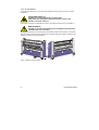
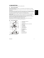
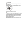
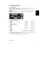
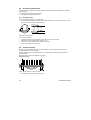
54Base Italiano Español Deutsch Français English Mounter and Laminator User Manual UM120EN, Rev.2.0 May.2004 Technical Bulletin Seal Brands … the finishing touch. Seal Graphics Technologies Corporation No.: TB54BASE001 Effective Date: 7/10/07 Subject: 54 Base Users' Manual Update IMPORTANT NOTICE English The section 5.5.5 should be omitted from the Users’ Manual. This application is not possible with this machine. Français La section 5.5.5 devrait être omise du manuel d'utilisateurs. Cette application n'est pas possible avec cette machine. Deutsch Der Abschnitt 5.5.5 sollte vom Benutzerhandbuch ausgelassen werden. Diese Anwendung ist nicht mit dieser Maschine möglich. Español La sección 5.5.5 demostrada abajo se debe omitir del manual de usuarios. Este uso no es posible con esta máquina. Italiano La parte 5.5.5 dovrebbe essere omessa dal manuale degli utenti. Questa applicazione non è possibile con questa macchina. P/N TB54BASE001, Revision A Page 1 of 1 7/10/07 Seal Graphics Technologies Corporation, 715 Progress Way Sun Prairie, WI USA 53590 Technical Service: (800) 486-6502 English All rights reserved All information included in this manual as well as information included in supplements or addendum to this manual is subject to copyright law. This information shall not be used, copied, reproduced, transmitted or disclosed to third parties without our prior written consent. SEAL Graphics assumes no responsibility for any errors that may appear in this document nor does it make expressed or implied warranty of any kind with regard to this material, including, but not limited to, the implied warranties of merchantability and fitness for a particular purpose. Seal Graphics shall not be liable for incidental or consequential damages in connection with, or arising out of the furnishing, performance, or use of this document and the program material which it describes. Français Tous droits réservés. Toutes les informations contenues dans ce manuel ainsi que celles des suppléments ou ajouts à ce manuel sont soumis aux lois sur le copyright. Ces informations ne doivent pas être utilisées, copiées, reproduites, transmises ou divulguées à des tiers dans notre autorisation préalable par écrit. SEAL Graphics n'accepte aucune responsabilité pour toute erreur pouvant apparaître dans ce document et ne donne aucune garantie tacite ou expresse eu égard à ce matériel, y compris mais sans s'y limiter, à toute garantie tacite de qualité marchande ou d'adaptabilité à un usage particulier. SEAL Graphics n'est pas responsable des dommages accessoires ou indirectes liés à ou découlant de la diffusion, performance ou l'utilisation de ce document et du matériel décrit. Deutsch Alle Rechte vorbehalten. Alle Informationen in diesem Handbuch sowie Informationen in Ergänzungen oder Zusätzen zu diesem Handbuch unterliegen dem Urheberrechtsgesetz. Die Informationen dürfen ohne unsere Genehmigung nicht verwendet, kopiert, wiedergegeben, übertragen oder an Dritte weitergegeben werden. SEAL Graphics haftet nicht für Fehler, die in diesem Dokument auftreten können, noch übernimmt SEAL Graphics Europe BV keinerlei ausdrückliche oder implizite Garantie in Bezug auf dieses Material, einschließlich, jedoch nicht begrenzt auf die implizierte Garantie der Marktgängigkeit und Eignung für einen bestimmten Zweck. SEAL Graphics haftet nicht für auftretende oder Folgeschäden in Verbindung mit oder entstehend aus der Ausstattung, Leistung oder Benutzung dieses Dokuments und des Programmmaterials, das es beschreibt. Español Reservados todos los derechos. Toda la información incluida en este manual y en los suplementos a anexos de este manual están sujetas a las leyes de derechos de autor. Queda prohibida la utilización, copia, reproducción, transmisión o divulgación de esta información a terceros sin nuestro consentimiento previo por escrito. SEAL Graphics no se hace responsable de los errores que pudieran aparecer en este documento ni tampoco ofrece garantía implícita o explícita de ningún tipo en relación con el material descrito, incluyendo, aunque sin que ello constituya un límite, las garantías implícitas de comercialización e idoneidad para una finalidad concreta. SEAL Graphics no responderá de los daños imprevistos o emergentes relacionados con, o que puedan surgir del suministro, funcionamiento o el uso de este documento y del material de programa que describe. Italiano Tutti i diritti riservati. Tutte le informazioni di questo manuale, nonché quelle dei supplementi o integrazioni a questo manuale sono soggette ai diritti d'autore (copyright) Queste informazioni non possono essere usate, copiate, riprodotte, trasmesse o comunicate a terze parti senza il nostro previo consenso scritto. SEAL Graphics Europa BV non si assume alcuna responsabilità per eventuali errori che possono comparire nel presente documento, né offre garanzia esplicita o implicita di alcun tipo in relazione a detto materiale, comprese, ma non limitatamente a, garanzie implicite di commerciabilità e adeguatezza per un particolare scopo. SEAL Graphics Europa BV non sarà responsabile per danni accidentali o indiretti relativi a, o derivanti dalla fornitura, dalle prestazioni, o dall'utilizzo del documento e dal materiale relativo al programma descritti. Seal Graphics Europe 2004, 2005 Seal Graphics Europe B.V., the Netherlands. P.O.Box 29 8100AA Raalte The Netherlands Tel.: 0031 572 346 000 Fax: 0031 572 346 001 INTRODUCTION Thank you for purchasing your SEAL 54Base. Maximum effort has been invested in the design of this machine to give you years of reliable service. As you become familiar with your machine you will appreciate the high quality of its output and the excellence in engineering stated in its smartly styled design. The machine described in this manual is a multi-functional machine that can perform the following processes; • high-quality lamination, • panel mounting of images, • mounting and laminating in one pass, • decaling. This manual gives a general description of various processes. A vast number of laminating products are available. All of them with their own applications and processing specifications. For more details on film choice and application solutions refer to the Seal films and adhesives product catalog. THIS MANUAL This manual is intended for the user of the 54Base. Read this manual carefully before starting the machine. This manual contains important information for correct installation, operation and maintenance of the machine. It also contains important instructions to prevent accidents, personal injury and/or serious damage prior to or during operation of the machine. Familiarize yourself thoroughly with the functioning and operation of this machine and strictly observe the directions given. If you have any questions or need further details on specific aspects related to this machine, please do not hesitate to contact us. The address and phone number are stated on the copyright page. Chapter 1 will provide you with a summary of the manufacturers warranty information. It also describes the safety features installed on the machine and gives a number of safety instruction and warnings. Read this chapter carefully. Chapter 2 provides a general description of the machine and of the process principles to help first time users to find their way on this machine. Chapter 3 specifies the machine and the materials to be used on this machine. Chapter 4 guides you through the installation and decommissioning of the machine. Chapter 5 guides you through the operation in various processes to develop basic knowledge of the machine. Chapter 6 provides maintenance procedures and trouble shooting suggestions in case the results are not up to your expectations. Chapter 7 is the glossary and explains a number of terms used in this manual. 2 User Manual 54Base TABLE OF CONTENTS 1.1 1.2 Warranty and Safety instructions Warranty 5 1.1.1 1.1.2 5 5 2 Warranty conditions Warranty period Safety 1.2.1 1.2.2 1.3 5 6 Safety features Safety instructions 6 7 Warnings 7 1.3.1 1.3.2 1.3.3 7 7 8 General ESD-warning In this manual On the machine Description 9 2.1 General description 9 2.2 Parts identification 9 2.3 Process principle 3 3.1 Specifications 10 11 Identification 11 3.2 Machine dimensions 11 3.3 Material specifications 12 3.4 Machine specifications 12 4 Installation 13 4.1 Unpacking 13 4.2 Installation 14 4.3 Transport 14 Table of contents English 1. 3 5 5.1 5.2 5.3 5.4 5.5 5.6 6 6.1 6.2 Operating 15 Process controls 15 5.1.1 5.1.2 15 17 Control panel Additional controls Operating modes 18 5.2.1 5.2.2 18 19 Normal mode Slow mode Placing film rolls 20 5.3.1 5.3.2 20 21 Auto-grip shafts Loading shaft with film rolls Webbing 22 5.4.1 5.4.2 5.4.3 5.4.4 5.4.5 22 23 23 24 25 Release liner and splitter bars Using the upper section only Upper and lower section Presetting the tension Pressure setting Processes and settings 26 5.5.1 5.5.2 5.5.3 5.5.4 5.5.5 5.5.6 26 27 27 27 28 28 Mounting images or decals Pre-coating panels Over-lamination Single-sided lamination Double-sided lamination Decaling Unloading 28 Maintenance 29 Cleaning 29 6.1.1 29 Cleaning the silicone covered rollers. Preventive maintenance 6.2.1 Auto-grip shafts 30 30 6.3 Trouble shooting 30 6.4 Technical assistance 31 7 4 Glossary 32 User Manual 54Base 1. WARRANTY AND SAFETY INSTRUCTIONS 1.1 Warranty The warranty period and conditions stated in this chapter are merely a summary of the general Seal warranty conditions. For the exact details on the warranty period and conditions for your machine, please contact your dealer. English 1.1.1 Warranty conditions The manufacturer warrants to the original end user* that the machine when proven defective in materials or workmanship, within the applicable warranty period will be repaired, or (at our option) replaced without charge. Note: The main rollers are subject to normal wear and tear and therefore have warranty on material defects only. The manufacturer or its representative shall not be liable for any damage caused by the machine nor loss of productivity. Warranty is voided when: • Changes or modifications are made to this machine, not explicitly approved by the manufacturer, • The machine is changed or modified by unauthorized persons, • The machine is used under other than normal working conditions, • The machine is used for purposes other than intended for (see page 3). * The original end user is the person that first purchased the machine from the manufacturer or its representative. 1.1.2 Warranty period The standard warranty period on this machine is one year from the date of purchase. This period however can be longer due to local law or purchase agreement. The main rollers have a warranty period of 6 months on material defects only. The warranty ends when: • The periods stated above have expired. • The machine changes possession. • Warranty is voided by any of the conditions mentioned above. Warranty and Safety instructions 5 1.2 Safety This machine is provided with safety equipment to promote safe machine operation. The manufacturer has done everything possible to prevent any possible danger and to inform you as accurately and comprehensively as possible of any hazards relating to the operation of the machine. You should nevertheless proceed with caution when operating the machine. Read the safety instructions below and familiarize yourself with the warning symbols summarized in the Warnings section. 1.2.1 Safety features Emergency stops The machine has 2 emergency stops. When activated the machine will come to a complete stop and the power to the motor controller is switched off. The emergency stops must be disengaged before a restart is possible. Optical safety devices The machine has an optical safety device at the front side of the nip at the main rollers. These devices perform a check of the operation between transmitter and receiver. When an error is detected (e.g. the signal is interrupted) the motor will stop and the motor controller will be disabled. The stop signal from the optical device is overruled when the slow mode is selected and the footswitch is pressed or when the reverse button is held. An audible signal is heard to warn for posible danger. Safety footswitch The safety footswitch is used as remote control to start and stop the machine in the normal and the slow mode. WARNING: THE OPTICAL SAFETY DEVICE IS DISENGAGED WHEN USING THE SAFETY FOOTSWITCH IN SLOW MODE. SO, KEEP CLEAR OF THE NIP WHEN PRESSING THE FOOTSWITCH, WHILE SLOW MODE IS ACTIVE. The safety footswitch is protected with a safety lock to prevent accidental switching. Insert the forefoot completely to disengage this lock. Slow mode The slow mode is used when setting up the machine with new films or images. When in slow mode the machine is started with the footswitch it will run at low speed so that the operator has both hands free to position and feed new film or image correctly into the machine. 6 User Manual 54Base 1.2.2 Safety instructions Work safely! The owner of the machine is responsible for safe operation of the machine. He therefore is obliged to familiarize operating personnel with the contents of this manual and make them aware of all possible hazards. Do not change, remove or disable the safety facilities. Warnings English 1.3 1.3.1 General ESD-warning WARNING: DANGER OF ELECTRIC SHOCK BY ELECTROSTATIC DISCHARGE. PROCESSING FILMS THROUGH LAMINATING ROLLERS WILL CAUSE BUILDUP OF ELECTROSTATIC CHARGES. An anti-static floor coating and wearing anti-static clothing and footwear can reduce the risk of ESD-shock. 1.3.2 In this manual In this manual you will find 3 levels of warnings. WARNING: THE WARNING MESSAGE IS USED WHEN A LIFE-THREATENING SITUATION MAY ARISE OR PERSONAL INJURY CAN OCCUR. FOLLOW THE INSTRUCTIONS CLOSELY. CAUTION: The caution message is used when there is danger of damage to the machine or materials. Follow the instructions to prevent this damage. Note: This message is used to give you useful information for easier operation, to prevent waste of material, etc.. Warranty and Safety instructions 7 1.3.3 On the machine On the machine (See Figure 1) you will find the following warning symbols in black on a yellow background. ROTATING PARTS (1) DANGER OF GETTING INJURED BY ROTATING PARTS. MAKE SURE THAT THESE ROTATING PARTS DO NOT CATCH YOUR FINGERS, CLOTHING, HAIR, ETC. This symbol is placed on in-feed table arms and on the cabinets just above the output table (1). ESD SHOCK (2) DANGER OF GETTING AN ELECTRIC SHOCK CAUSED BY ELECTROSTATIC CHARGE BUILD-UP IN THIS AREA. This symbol is placed on those places where electrostatic charges can be build-up. The machine parts close to the nip and the output material are most likely building up charges. Therefore ESDsymbols are placed on the image guide (2) Figure 1: Warning symbol locations. 8 User Manual 54Base 2 DESCRIPTION This chapter describes the machine and its operating basics. General description The machine described in this manual is a mono-directional machine dedicated for processing pressure sensitive materials. While feeding through images and the coating films, the two silicone coated main rollers generate the pressure. The area where the upper and lower main roller meet is called the “nip”. The upper main roller can be moved up or down manually, so the nip can be varied to feed materials of various thicknesses. The nip setting hand wheel also sets the pressure for the laminating process. The lower main roller is motor driven. The speed can be manually set between zero and a given maximum value. The top roller is equipped with a heater to assist in the lamination process. The heat assist makes the adhesive more active and allowes it to spread more evenly, which improves the results. The machine has two material unwind shaft positions in the rear. The supports in the upper front position can clamp a (plastic) cilinder used for release liner wind-up. The machine can be divided into an upper and a lower section. The upper section, above the in-feed table, is suitable for unwind material with release liner. The lower section can only unwind material without release liner. 2.2 Parts identification 1 2 3 4 5 6 7 8 9 10 11 12 13 14 15 16 Castors and leveling feet Foot switch Unwind shaft Nip setting and pressure control wheel Main rollers In-feed table Image guide Wind-up shaft Heat assist switch Control panel Emergency button Splitter bars Heater Output table Identification label Main power entry Figure 2: Main parts identification. Description 9 English 2.1 2.3 Process principle In all processes the materials are fed through the nip from the front side to be joined together by pressure. A process that makes maximum use of the machine is shown in Figure 3. Shown is a double sided laminating (decalling) process. The top coating film is a pressure sensitive film with release liner (3) taken from a supply roll on the (rear) upper unwind shaft (5). The bottom coating film is a pressure sensitive (mounting) film without release liner taken from a supply roll on the lower unwind shaft (9). Figure 3: Creating Pop-up art, including image supply from roll. The image that has to be coated on both sides is fed between the main rollers (1) via the in-feed table (2). When using a pressure sensitive laminate, it often has a release liner (3) that has to be removed. As in the top half, it runs via a splitter bar (6) where the release liner is removed. This release liner is rolled up onto the wind-up shaft (4) in the upper section. When using a pressure sensitive laminate without a release liner (like in the bottom section), it must not run via the splitter bar to avoid the film sticking to the bar and leaving adhesive residue behind. A mounting film has adhesive on both sides and release liner on just one side. This release liner has to stay on until the image is mounted. So a mounting film is processed in the bottom section the same way as a laminate without release liner. The upper main roller can be heated (7) to a fixed temperature of 40 degrees. This is called ‘heat assist’ and can be used to activate the adhesive to flow more evenly and get a better bonding between laminate and image. 10 User Manual 54Base 3 SPECIFICATIONS 3.1 Identification The machine identification label (example in Figure 4) is located at the bottom of the right-hand cabinet, on the rear side of the machine. This label indicates the model (version) and the power supply requirements. English CAUTION: The mains supply must match the values indicated on the machine identification label. Figure 4: Machine identification label (example). 3.2 Machine dimensions Uncrated: Metric American Width 190.5 cm 75.0 in. Height 132.6 cm 52.2 in. Depth (excl. table) 47.7 cm 18.8 in. Depth (incl. in-feed table) 55.0 cm 21.7 in. Working height 90 cm 35.4 in. Weight 232 kg 512 lbs Crated: Width 200 cm 78.7 in. Height 162 cm 63.8 in. Depth 90 cm 35.4 in. Weight 270 kg 595 lbs Working area: Width 342 cm 135 in. Depth 190 cm (75 in.) + 2x maximum board length Note: Anti-static clothing and footwear of the operator and an anti-static floor coating will help reduce the build-up of electrostatic charges (ESD). A relative humidity of at least 70% also helps reducing ESD-build-up. Specifications 11 3.3 Material specifications Maximum width: Process up to 40°C (104 °F) Maximum roll diameter: Material unwind (upper unwind) Material unwind (bottom unwind) Release liner wind-up Maximum panel thickness: Roll core inside diameter: 3.4 Metric 1400 mm 240 305 160 50 76.2 mm mm mm mm mm American 55.1 in. 9.4 1 6.3 2.0 3.0 in. ft. in. in. in. Machine specifications Power supply requirements: Europe 1N/PE 230VAC +/- 10%, 50/60Hz, 8.5A USA 1N/PE 230VAC +/- 10%, 50/60Hz, 8.5A For the correct supply voltage version refer to the identification label on the machine. Standard number of shaft positions: Material unwind Release liner wind-up Optional features: Nip setting: Pressure: Process speed: Maximum Slow mode Maximum roller temperature: Noise level 12 2 (auto-grip) 1 0–52 mm 0.3–1.0 N/mm 5 0.6 40 m/min m/min °C 0 – 2.05 1.71 – 5.71 in. lbf/in. 16.4 2.0 104 ft/min ft/min °F <70 dB(A) User Manual 54Base 4 INSTALLATION WARNING: INSTALLATION MUST BE CARRIED OUT BY SKILLED PERSONNEL. Unpacking At delivery, the machine is packed in a plastic bag to avoid moisture penetration. It is transported in a carton box and is fastened onto a wooden pallet. Place the pallet in a space where there is enough room to roll the machine off from the pallet (approx. 5.5 m). To unpack, follow the steps below (refer to Figure 5); 1. Cut the straps, lift off the carton box, remove the plastic bag and put the accessories aside. 2. Place the two ramps (4) against the roll-off side of the pallet so that the castors (5) will run clear from the edge. Figure 5: Ramp positioning. 3. 4. 5. 6. 7. Remove the four securing bolts (1). Turn down the four leveling feet (2) to lift the machine and remove the wooden blocks (3). Unscrew and remove the support block (6) to make room for the machine to pass by. Turn up the four leveling feet (2) completely to put the machine on its castors (5). Roll the machine off carefully from the pallet using the ramps. WARNING: ROLL THE MACHINE OFF WITH 2 PERSONS. IT IS HEAVY AND CAN NOT BE CONTROLLED ALONE. Note: Save all packing material for later moving over long distances or discard of according to local regulations. Installation 13 English 4.1 4.2 Installation Note: Make sure that the machine, in its final location, has adequate space. You will need room to feed, receive and trim images. See Figure 6. L = Maximum board length, S = Minimum space 60 cm.(24”). Figure 6: Working space. 1. Move the machine (and the accessories) to its final location. 2. Turn down the four leveling feet until the castors are off the floor. 3. Remove all transport material. • • • Cut the straps around the shaft supports and remove the foam pads, Cut the straps holding the in-feed table arms, Cut the straps around the main roller axis and move up the top main roller to remove the transport blocks from the nip, 4. Put a spirit level (horizontal) on the upper main roller and (vertical) against the front of both cabinets to level the machine by adjusting the four leveling feet. CAUTION: Check the mains values before connecting. See section 3.4 for power supply details. Only if absolutely necessary, use an extension cable of ample capacity. Unroll the extension cable completely. 5. Connect the machine to the mains using the power cable supplied with the machine. WARNING: MAKE SURE THE POWER SUPPLY CABLE AND/OR THE EXTENSION CABLE IS NOT BLOCKING YOUR WAY AROUND THE MACHINE. 4.3 Transport The machine can be transported on a smooth surface on its castors. CAUTION: Turn the leveling feet up completely to prevent them from bending or breaking if accidentally bumping into an obstacle. When moving the machine on rough surfaces or over long distances, use the original pallet and packing material and and move it with a pallet truck or forklift. 14 User Manual 54Base 5 OPERATING 5.1 Process controls This section gives an overview of the functions of the controls on the control panel (Figure 7) and elsewhere on the machine (Figure 8). Note: Switch on the heat assist approximately 15 minutes before use, if a process requires the rollers to be heated. Close the nip and let the machine run at low speed, to avoid uneven hot spots. 5.1.1 Control panel This paragraph describes the controls and indicators on the control panel. Figure 7: Control panel Control ON/OFF (1), toggle pushbutton and standby or ON indication LED; Press the switch 1 second to switch the machine from stand by to active and back. The LED flashes when the machine is in stand-by mode. WARNING: THE MACHINE IS CONSTANTLY POWERED WHEN THE POWER CORD IS PLUGGED IN. Operating 15 English This chapter describes the function of the controls and indicators, the operating modes, how to set up and operate the machine and a number of applications. The sections in this chapter are placed in a sequence in which the information is needed for laminating processes. For the mounting process the sections 5.3 and 5.4 can be skipped with the exception of setting the pressure (see section 5.4.5). Pressure indication (2), 4 LED’s; The LED’s indicate the pressure setting of the main rollers. When 2 LED’s light at the same time, they indicate the tens in between. See specifications for actual pressure range. All four LED’s flashing indicates a pressure or nip setting error. The LED’s start flashing at 10% overload. When the pressure exceeds a 20% overload an audible signal is generated. Increase the nip to lower the pressure. Speed control (3), control knob; Sets the speed anywhere in a range between 0 and 10 (See specifications for actual speed range). Slow mode (4), toggle pushbutton; Press 1 second to switch slow mode ON or OFF. To run at the fixed slow mode speed the footswitch must be pressed. The LED will light when slow mode is selected. CAUTION: When slow mode is active the machine can still run at high speed. Slow mode indication is NOT a speed indication. It is a working method. Safety indicator (5), LED; The LED will light up when the beam of the optical safety device at the input side of the nip is not interrupted. Forward (6), pushbutton; Press to start the rotation of the rollers in the forward direction. The LED will light when the forward mode is selected. When the LED flashes it indicates a motor overload. Press the stop button and check the material flow and the tension setting of the unwind shafts. Reverse (7), snap pushbutton; Press and hold for rotation of the rollers in reverse direction. The LED will light when the reverse mode is selected. When the LED flashes it indicates a motor overload. Press the stop button and check the material flow and the tension setting of the wind-up shafts. Forward and reverse indicator flashing; This indicates a system error. Disconnect and then reconnect the power. If the error persists, contact your service organization. Stop (8), pushbutton; Press to stop the rotation of the rolls. Heat-assist (9), ON/OFF switch Switches the heat-assist control ON or OFF. When ON the upper roller will be heated untill it reaches 40 °C or 104 °F. Allow ample time to reach this temperature. 16 User Manual 54Base Additional controls English 5.1.2 Figure 8: Additional controls Emergency stop buttons (1), push and hold button; When pressed the rotation of the rolls is stopped immediately and the button is locked into this stop position. Turn the button to unlock it. Pressing start, reverse or pressing the footswitch starts the process again. Nip setting wheel (2), geared wheel; Turn the wheel clockwise to narrow (close) the nip and set pressure or counter-clockwise to release pressure and widen (open) the nip. When both rollers touch the materials, the pressure is set. By turning the wheel clockwise the pressure is increased. Turning the nip setting wheel counter-clockwise the pressure will decrease. The pressure is indicated on the control panel by 4 LED’s. Foot switch (3), snap switch; Press and hold the switch to start the rotation of the rolls. Insert the forefoot completely to disable the safety lock that prevents accidental starting. When the switch is released, the rotation of the rolls will stop. In-feed table (4) The in-feed table can swing up around the pivot point at the top of the table arms. The image guide is clamped to the table arms and can be removed by pulling it forward from its retaining blocks. Unwind tension control (5), ring; By turning this ring counter-clockwise (top to rear) an amount of friction is set between the shaft and the frame, so this will act as a brake. Tightening the brake will apply more tension to the material on the shaft. Turning the ring clockwise (top to front) will release the brake and therefore release the tension. Operating 17 5.2 Operating modes The machine is either in normal mode, or slow mode. In both normal and slow mode the rollers can rotate in forward or in reverse direction. 5.2.1 Normal mode When slow mode is not activated (normal mode), the rotation speed of the rollers is set via the speed control knob. Start rotation by pressing the forward button, the reverse button or the footswitch. Rotation stops when a stop button is pressed or the footswitch is released. Note: To return control from the footswitch to the control panel without stopping, press and hold the forward button, release the footswitch and then release the forward button. An interruption of the light beam of the optical safety device in front of the rollers will also stop the rotation of the rollers. To continue after the interruption is taken away, the process must be started again. Reverse WARNING: KEEP CLEAR OF THE REAR SIDE NIP WHEN RUNNING IN REVERSE MODE. When running in reverse, the optical safety device at the front side nip is ignored. An audible tone is heard to warn you for posible danger. The speed is determined by the speed control. 18 User Manual 54Base 5.2.2 Slow mode Normal speed Press the forward or reverse button in slow mode to run at a normal speed determined by the speed control setting (see normal mode). To start at slow mode speed or to switch from normal (forward) to slow mode speed just press and hold the footswitch (when slow mode is selected). Slow mode speed Press and hold the footswitch in slow mode to force the rollers to run forward at a fixed low speed (see specifications) independent from the speed control. Slow mode speed is always running in forward direction. Slow mode speed in reverse direction is not possible. WARNING: KEEP CLEAR OF THE NIP WHEN RUNNING AT SLOW MODE SPEED. When running at slow mode speed, the optical safety devices are ignored and an audible signal is heard to indicate danger. When the footswitch is released, the forward rotation is stopped. Note: To change from slow mode speed to normal speed without stopping, press and hold the start button, release the footswitch and then release the start button. Changing to normal speed will not deactivate slow mode. Pressing the footswitch again will slow down rotation to slow mode speed again. Operating 19 English Enter or leave Slow mode by pressing the slow mode button for 1 second. The selection is indicated by the slow mode indication LED. Entering slow mode will not change anything to the current movement of the rollers. In slow mode the rollers can run at normal or at slow mode speed. 5.3 Placing film rolls This section describes the loading of the machine with laminating or mounting films. The films are loaded onto the shafts at the rear side of the machine. Note: Always work in the center of the machine. Select films that are slightly wider than the print width of the image. This way the print can be trimmed with a border, but waste is reduced. 5.3.1 Auto-grip shafts Both shafts in the rear of the machine are the same. The shafts fit into the machine in both ways. On the control panel side of the machine all the shafts and the supports snap together. A spring inside the left-hand side support pushes the shaft into locking position when the shaft is turned. To position the shaft correctly turn the shaft until it locks in. Check the auto-grip mechanism on each shaft. The rubber cords should just not touch the edges of the recess (Figure 9A: d = 8 ± 2.5 mm = 1/3 ± 1/10 in.). If not, see chapter 6 Maintenance. Figure 9: Auto-grip shaft When the shaft is rotated inside a cylinder, the rubber cord will move to the side and gets caught between shaft and cylinder (Figure 9B). Rotating back will release the cord. Auto-grip shaft lock. To prevent the auto-grip shaft from jumping out of its support, a locking plate is installed on the left hand support. To take out the auto-grip shaft: Figure 10: Auto-grip locking bracket. 1. Hold the locking plate (C) with your right hand at (A) in the upper position ((B) is above the shaft). 2. Push the shaft with your left hand, to the right against the spring and remove it from the support at your left-hand side. 3. Now with both hands take out the shaft. 20 User Manual 54Base 5.3.2 Loading shaft with film rolls English The film roll is put on the shaft depending on the type of film and the use in the upper or lower section of the machine. In general pressure sensitive film with release liner (A) is rolled up with the liner (3) and adhesive (2) to the outside of the film (1), whereas film without release liner (C) has its adhesive layer to the inside of the roll. However North American pressure sensitive films in general have the release liner on the inside of the roll (B). Figure 11: Film rolls. • • In the upper section, the adhesive (2) side in contact with the image and the release liner (3) must be on the top when unwinding the film to the front of the machine. In the lower section, the adhesive (2) side in contact with the image must be on the bottom when unwinding the film to the front of the machine. Figure 12: Film adhesives. 1. Take the auto-grip shafts from the unwind positions of the machine. 2. Slide the shafts into the film rolls. 3. Place the shafts back into their supports as described above. Unwind direction of film towards the front of the machine: in the upper section; • film with release liner on the outside unwinds from the top (A), • film with release liner on the inside unwinds from the bottom (B), • film without release liner unwinds from the bottom (C). in the lower section; • film without release liner unwinds from the top (D). 4. Turn the shaft until the grippers lock in. 5. Position the film and the scrap core in the middle and align them. Note: When both upper and lower section are used, place both films at exactly the same position. 6. Make sure the films are set up and aligned properly. Operating 21 5.4 Webbing For laminating processes the machine must be webbed before images on thin film or on panels can be processed. The machine can be webbed for single sided or double sided processing. When mounting images the machine is not webbed. Note: In single sided processes adhesive residues will stay behind on the bottom roller where the film is wider than the images. To prevent this, use film of the same width as the image. Or, a release liner of the same width as the top film can be used in the bottom section. The release liner can easily be removed later on. When processing panels, a leader panel (waste panel equal to the panels to process) is needed to feed in the film and set the pressure and tension. When processing thin images a release board is needed to feed in the film. When this panel is through, the nip is set to zero and the images can be fed. The release board is then cleaned and can be used again. 5.4.1 Release liner and splitter bars In the upper section, when processing film with release liner, the splitter bar is used to split release liner from the film. The release liner is wound-up on the tube in the front of the machine. Figure 13: Use of a splitter bar. The film with release liner (A) is running underneath the splitter bar, where the release liner is split off. Film without release liner (B) would leave adhesive remains behind on the splitter bar, so this is lead over the splitter bar In the lower section (C), the film is running underneath the splitter bar to avoid adhesive remains staying behind on it. 22 User Manual 54Base English 5.4.2 Using the upper section only Figure 14: Webbing upper section. 1. Remove the image guide. 2. Unwind the film from the upper or top unwind roll. • • Feed a film without release liner over the splitter bar (A). Feed a film with release liner underneath the splitter bar (B). 3. Pull the film forward until approximately 10 cm (4 in.) is on the in-feed table. If the film has a release liner: • • Peel off the release liner. Pull the release liner up and stick it to the tube on the wind-up position. 4. Stick the leader panel to the film and feed the panel into the nip using slow mode. Note: Use a carrier board when processing thin images. 5.4.3 Upper and lower section Figure 15: Upper and lower section webbed. The film in the upper section is webbed first 1. Feed the film underneath (B) the splitter bar (between splitter bar and upper roller) • Film without a release liner must be fed over the splitter bar (A). Operating 23 2. Pull the film forward until it almost reaches the in-feed table and apply it to the upper roller. If the film has a release liner (B): • • Peel off the release liner, Pull it up and stick it from below onto the tube on the wind-up position. Now web the lower section Figure 16: Webbing lower section. 3. Lift the in-feed table and put it in the upper position (A). 4. Unwind the film from the lower unwind roll. 5. Pull the film forward underneath the splitter bar until the end reaches above the nip and stick it to the film from the upper section. 6. Lower the in-feed table. 7. Push the films with a leader panel (C) into the nip using slow mode (B). Note: Use a leader panel of the same material, thickness and width as the panels to process. Use a release board when processing thin images. 5.4.4 Presetting the tension To enable the film to unwind without wrinkles tension (brake) can be set to the roll. On the right-hand (control panel) side of the machine you will find a tension control ring on each shaft. Turn the tension control ring counter-clockwise (top to rear) to set the tension or clockwise (top to front) to release the tension. When the film is webbed, it is recommended to set a low tension to each shaft by turning the ring counter-clockwise until you feel some resistance. This will prevent film from unwinding without tension. 24 User Manual 54Base 5.4.5 Pressure setting Thin images When processing thin images (printer output, posters, etc.) pressure is preset when the upper and lower material is webbed. When the leader panel or release board is through the nip, the nip is set to zero and pressure is preset. The best pressure setting for thin films is about 80%. During processing the pressure can be adjusted. English CAUTION: Soft panels (Foam) require less pressure. Set the pressure proportional to the rigidity of the foam between 40% and 80% to avoid permanent compression marks. Panels When processing panels, a leader panel is used to web the film(s). This leader panel is at the same time used to preset the pressure. Use a leader panel of the same material, thickness and width as the panels to process. 1. Set the nip to the thickness of the panel. 2. Feed the leader panel into the nip in slow mode. 3. When the edges of the film(s) are through the nip, set the pressure to approximately 80% for full-width panels. CAUTION: For narrower (or soft) panels set the pressure proportional to the width (rigidity) between 40% and 80%. E.g. half width equals 60%. Mounting boards Use a leader panel of the same material, thickness and width as the panels to process. 1. Set the nip to the thickness of the panel. 2. Feed the leader panel into the nip in slow mode. 3. When the panel is halfway in the nip, set the pressure between 70 and 80% for full-width panels. CAUTION: For narrower (or soft) panels set the pressure proportional to the width (rigidity) between 40% and 80%. E.g. half width equals 60%. 4. Back-up the panel out of the nip Note: The image will add approximately an additional 5 to 10% to the pressure. Operating 25 5.5 Processes and settings 5.5.1 Mounting images or decals In this process the machine is not webbed with film. • When mounting images onto a (pre-coated) board (B), the adhesive is on the mounting side of the board. • When mounting decals (A), the adhesive is on the back of the image. The mounting process is equal for both. 1. 2. 3. 4. Remove the shaft from the upper front position. Preset the nip and the pressure (see section 5.4.5). Put the board on the in-feed table. Put the image on top of the board (image side up). Turn back the image at the machine side (1). 5. Turn back approx. 25 mm (1.0 in.) release liner (2) at the machine side and crease this evenly from the inside out. Note: The final quality depends on the way in which the leading edge of the image is applied to the board. 6. Apply the image (3) to the board (C). 7. Insert the edge with the image adhered to into the nip (D). 8. Lay the loose end (4) of the image smoothly over the upper roller. Figure 17: Mounting images or decals Note: Use the footswitch to start/stop in slow mode, keeping your hands free. WARNING: KEEP YOUR FINGERS CLEAR OF THE NIP. THE OPTICAL SAFETY DEVICE IS NOT FUNCTIONING WHEN USING THE FOOTSWITCH IN SLOW MODE. 9. With your left hand - peel back the release liner (6) from the image or board as it is slowly fed into the nip one section at a time, without stopping. Note: Removing the release liner completely exposes the adhesive to dirt and dust that will get trapped under the image. 10. With your right hand - keep the image smooth against the upper roller (5), preventing the image from wrinkling. Note: For the best result; do not stop while feeding an image. 26 User Manual 54Base 5.5.2 Pre-coating panels This process is used to coat boards (substrates) with a pressure sensitive mounting film onto which images can be mounted. This process can also be used to create a carrier board. In this case a film with a non-stick surface is used. Note: The mounting film is usually provided with one release liner. Place the film in the upper section and web it as if it has no release liner (over the splitter bar). Place the roll of mounting film on the shaft of the upper unwind position. Set the nip to correspond to the thickness of the panels to be processed. Web the film using a leader panel of the same material, thickness and width. English 1. 2. 3. 4. 5. Set the pressure while feeding the leader panel. Before the end of the leader panel enters the nip, butt up the panel to be pre-coated. • When more panels have to be pre-coated feed them in continuously without gap. • At the end, use a leader panel again to finish. This prevents the adhesive from touching the bottom roller. 6. End with a leader panel and feed this board until the previous panel is out of the nip. CAUTION: Do not cut film close to or on the rollers. This will damage the silicone coating of the rollers and will void the warranty. 7. Cut this panel free using a blade cutter. 8. Back-up the leader panel using the reverse. 9. Cut the film using a safety blade cutter. After removing the release liner from the pressure sensitive mounting film, the board has an adhesive coating ready to mount an image. See section 5.5.1 for mounting images. 5.5.3 Over-lamination After an image is mounted to a panel, a protective laminate can be applied. This process is the same as pre-coating a board (section 5.5.2). The over-laminate can be a pressure sensitive adhesive with or without release liner. 5.5.4 Single-sided lamination Images can be laminated single-sided with or without using carrier (or release) boards. This laminate can be a pressure sensitive adhesive with or without release liner. Disadvantage of the single sided lamination process is the adhesive residue that can stay behind on the rollers where there is no image. To avoid this, carrier boards or release liner can be used. Or the image must be wider than the laminate and pieces of scrap material must be used to begin and end with. Using carrier boards • Web the upper section of the machine as described above (section 5.4.1). • Put the image on a carrier board with the image side up and follow the steps for pre-coating a board (section 5.5.2). Operating 27 Using release liner • Use a roll of release liner in the lower section. • Web the upper and lower section of the machine as described above (section 5.4.3). When the images are cut from the result, the release liner will separate from the image automatically. 5.5.5 Double-sided lamination Encapsulating images with cold laminates is called double-sided lamination (and is normally not done with panels). Note: In the lower section only laminate without release liner can be used. 1. Load and web laminating films in the upper and the lower section as described in section 5.4.3. 2. When the leader panel is completely out of the nip, lower the upper roller onto the bottom roller (nip setting = 0) and set the pressure to approximately 80%. 3. Now feed the images into the nip, allowing a gap between them. 4. Cut the result with a safety blade cutter when the images are clear of the rollers. 5.5.6 Decaling When decaling, a laminate is put over the image side and an adhesive backing is put on the backside of the image. The process is the same as double-sided lamination (section 5.5.5). 1. Load and web laminating films in the upper and the lower section as described in section 5.4.3. 2. When the leader panel is completely out of the nip, lower the upper roller onto the bottom roller (nip setting = 0) and set the pressure to approximately 80%. 3. Now feed the images into the nip, allowing a gap between them. 4. Cut the result with a safety blade cutter when the images are clear of the rollers. This decal can later be mounted onto a panel or other substrate. 5.6 Unloading To unload the machine: 1. Cut the result after the last image (panel before the leader panel). 2. Cut both films along the splitter bar using a safety blade cutter. 3. Open up the nip and remove the (leader panel and) films from the rollers at the rear. To unload a roll from the shaft: 4. Turn the material roll in the wind-up direction to free the autogrip cords. 5. Take out the autogrip shaft. 6. Remove the material roll from the autogrip shaft. 28 User Manual 54Base 6 MAINTENANCE 6.1 Cleaning The machine has to be cleaned regularly. Dirt and dust will have a negative influence on the result of the lamination processes. English CAUTION: Do not use abrasive materials for cleaning the machine. This can damage the painted surfaces or the silicone covering of the rollers. Use a damp cloth for cleaning. CAUTION: Make sure water does not run into any of the cabinets. This can damage the electrical circuits when power is applied. Clean the exterior of the machine with a damp cloth as needed. If necessary, use a householdcleaning solution to remove difficult marks. Clean the shafts and the rubber cords on it as required. 6.1.1 Cleaning the silicone covered rollers. The rollers must be cleaned regularly to prevent a build-up of adhesive residue. This may eventually damage the rollers. Use a damp lint-free cloth to remove dust and other dirt. Use a silicon-cleaning block to remove the adhesive stains from the rollers. Note: Adhesive is easier to remove when the rollers are hot. Put a waste panel between the rollers when cleaning the upper roller, to prevent adhesive remnants from falling onto the lower roller. WARNING: MAKE SURE THE ROLLERS ARE COLD WHEN USING ALCOHOL FOR CLEANING. ISOPROPYL ALCOHOL IS VERY FLAMMABLE. Difficult stains can be removed with the aid of isopropyl alcohol (IPA) and a clean lint-free cloth. Do not pour isopropyl alcohol directly on the machine. Maintenance 29 6.2 Preventive maintenance Our machines are designed in such way that they need little (preventive) maintenance in addition to the cleaning. The following checks have to be performed: • Auto-grip shafts with blocking cords. 6.2.1 Auto-grip shafts Check the auto-grip mechanism on each shaft. • The distance (d) between the rubber cords and the edges of the recess should be 8 ± 2.5 mm minimum (the cord must not touch the skew). 3 2 1 d A B Figure 18: Auto-grip shaft If not, correct as follows: • Loosen the clamp (2) with the screw (1) until the cord is free on one side, • Shorten the cord by approximately 10 mm (0.4 in.), • Put the end of the cord back underneath the clamp (2), • Secure it by tightening the screw (1). 6.3 Trouble shooting During processing wrinkles can show up in the image (1) on the in-feed table (2) and in the process result (4) on the output table. The figures below show some examples where it is caused by the main rollers (3) and gives a possible solution. Wait until a few meters is processed to see results. Pressure too high. Figure 19: Wrinkles due to high pressure. • 30 Decrease the roller pressure a little (5-10%). User Manual 54Base Pressure too low. Figure 20: Wrinkles due to low pressure. Increase the roller pressure a little (5-10%). English • Unwind tension too low. Figure 21: Wrinkles due to low unwind tension. • Increase the unwind tension until the wrinkles (6) in the film on the roller disappear. The lines (7) in the process result will disappear as well. Roller alignment fault. Figure 22: Wrinkles due to faulty roller alignment. The wrinkles occur on one side only (left or right). • This is a machine adjustment error. Contact your dealer and ask for technical assistance. 6.4 Technical assistance For technical assistance you can contact your dealer or the address on the copyright page in the front of this manual. Make a clear description of the problem before contacting technical assistance. Please keep the type and serial number of your machine at hand. You can find this data on the identification plate of your machine, which can be found on the rear side of the right cabinet. Maintenance 31 7 GLOSSARY Carrier board or sled A board with a non-stick surface that is used to support the image when laminating one side of an image only. Decal An image with an adhesive backside (Am.: Sticker). Decaling Providing an image with laminate on the image side and adhesive on the backside. Encapsulating Sandwiching an image between two heat sensitive films. (Not possible on this machine.) Laminate A thin film of clear material to be permanently affixed onto an image. Laminating Providing an image with a thin film of clear material. Leader panel A (waste) piece of rigid foam board with the same specifications as the panels to process. It is used to lead film into the nip of the main rollers and to set the pressure. Main rollers A set of two silicone coated rollers that perform the actual process. Mounting Permanently affixing an image onto a backing board. Mounting film Adhesive backing to make an image self-adhesive. On the side that is in contact with the image the carrier has an adhesive with or without release liner. The carrier can function as release liner or be supplied with a second (cold) adhesive layer and release liner. Nip The area where the top and bottom main rollers meet is called the nip. Pre-coating Coating a substrate with an adhesive mounting film onto which an image can be mounted. Release board Thin (plastic) board with a non-stick surface on both sides. Used when webbing for non-panel processes. This board can be cleaned and used more than once. Release liner Backing film protecting the adhesive layer of a laminate or mounting film. Once the release liner is removed, the adhesive layer becomes exposed. Roll A (shaft with a) cylinder loaded with film or release liner. Roller One part of the main element in the machine that performs the actual process (see main rollers). Scrap core An empty cardboard cylinder left over when all material on a roll is used. Webbing Loading the machine with film, so that the machine is ready for processing. 32 User Manual 54Base