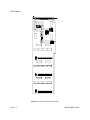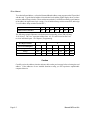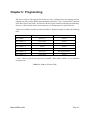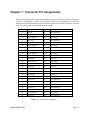
1
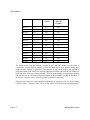
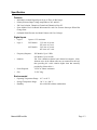
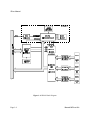
ACCES I/O PRODUCTS INC
10623 Roselle Street, San Diego, CA 92121
TEL (858)550-9559 FAX (858)550-7322
MODEL IDI-xx
USER MANUAL
FILE: MIDI-xx.A6c
Notice
The information in this document is provided for reference only. ACCES does not assume any liability arising
out of the application or use of the information or products described herein. This document may contain or
reference information and products protected by copyrights or patents and does not convey any license under
the patent rights of ACCES, nor the rights of others.
IBM PC, PC/XT, and PC/AT are registered trademarks of the International Business Machines Corporation.
Printed in USA. Copyright 1995 by ACCES I/O Products Inc, 10623 Roselle Street, San Diego, CA 92121.
All rights reserved.
Pageiii
Warranty
Prior to shipment, ACCES equipment is thoroughly inspected and tested to applicable specifications. However,
should equipment failure occur, ACCES assures its customers that prompt service and support will be
available. All equipment originally manufactured by ACCES which is found to be defective will be repaired
or replaced subject to the following considerations.
Terms and Conditions
If a unit is suspected of failure, contact ACCES' Customer Service department. Be prepared to give the unit
model number, serial number, and a description of the failure symptom(s). We may suggest some simple tests
to confirm the failure. We will assign a Return Material Authorization (RMA) number which must appear on
the outer label of the return package. All units/components should be properly packed for handling and
returned with freight prepaid to the ACCES designated Service Center, and will be returned to the
customer's/user's site freight prepaid and invoiced.
Coverage
First Three Years: Returned unit/part will be repaired and/or replaced at ACCES option with no charge for
labor or parts not excluded by warranty. Warranty commences with equipment shipment.
Following Years: Throughout your equipment's lifetime, ACCES stands ready to provide on-site or in-plant
service at reasonable rates similar to those of other manufacturers in the industry.
Equipment Not Manufactured by ACCES
Equipment provided but not manufactured by ACCES is warranted and will be repaired according to the
terms and conditions of the respective equipment manufacturer's warranty.
General
Under this Warranty, liability of ACCES is limited to replacing, repairing or issuing credit (at ACCES
discretion) for any products which are proved to be defective during the warranty period. In no case is
ACCES liable for consequential or special damage arriving from use or misuse of our product. The customer
is responsible for all charges caused by modifications or additions to ACCES equipment not approved in
writing by ACCES or, if in ACCES opinion the equipment has been subjected to abnormal use. "Abnormal
use" for purposes of this warranty is defined as any use to which the equipment is exposed other than that use
specified or intended as evidenced by purchase or sales representation. Other than the above, no other
warranty, expressed or implied, shall apply to any and all such equipment furnished or sold by ACCES.
Page iv
Table of Contents
Notice . . . . . . . . . . . . . . . . . . . . . . . . . . . . . . . . . . . . . . . . . . . . . . . . . . . . . . . . . . . . . . iii
Warranty . . . . . . . . . . . . . . . . . . . . . . . . . . . . . . . . . . . . . . . . . . . . . . . . . . . . . . . . . . . ii
Chapter 1: Introduction . . . . . . . . . . . . . . . . . . . . . . . . . . . . . . . . . . . . . . . . . . . . . . 1-1
Description . . . . . . . . . . . . . . . . . . . . . . . . . . . . . . . . . . . . . . . . . . . . . . . . . . . . . . . . . . . 1-1
Specification . . . . . . . . . . . . . . . . . . . . . . . . . . . . . . . . . . . . . . . . . . . . . . . . . . . . . . . . . . 1-3
Chapter 2: Installation . . . . . . . . . . . . . . . . . . . . . . . . . . . . . . . . . . . . . . . . . . . . . . 2-1
CD Installation . . . . . . . . . . . . . . . . . . . . . . . . . . . . . . . . . . . . . . . . . . . . . . . . . . . . . . . . .
3.5-Inch Diskette Installation . . . . . . . . . . . . . . . . . . . . . . . . . . . . . . . . . . . . . . . . . . . . . .
Directories Created on the Hard Disk . . . . . . . . . . . . . . . . . . . . . . . . . . . . . . . . . . . . . . .
Installing the Card . . . . . . . . . . . . . . . . . . . . . . . . . . . . . . . . . . . . . . . . . . . . . . . . . . . . . .
2-1
2-1
2-2
2-4
Chapter 3: Option Selection . . . . . . . . . . . . . . . . . . . . . . . . . . . . . . . . . . . . . . . . . . 3-1
Chapter 4: Address Selection . . . . . . . . . . . . . . . . . . . . . . . . . . . . . . . . . . . . . . . . . 4-1
Chapter 5: Software . . . . . . . . . . . . . . . . . . . . . . . . . . . . . . . . . . . . . . . . . . . . . . . . . 5-1
Chapter 6: Programming . . . . . . . . . . . . . . . . . . . . . . . . . . . . . . . . . . . . . . . . . . . . . 6-1
Chapter 7: Connector Pin Assignments . . . . . . . . . . . . . . . . . . . . . . . . . . . . . . . . 7-1
Page v
List of Figures
Figure 1-1: IDI-48 Block Diagram . . . . . . . . . . . . . . . . . . . . . . . . . . . . . . . . . . . . . . . . . . . . 1-4
Figure 3-1: IDI-48 Option Selection Map . . . . . . . . . . . . . . . . . . . . . . . . . . . . . . . . . . . . . . . 3-2
List of Tables
Table 4-1: Standard Address Assignments for 286/386/486 Computers . . . . . . . . . . . . . . . 4-1
Table 6-1: Address Selection Table . . . . . . . . . . . . . . . . . . . . . . . . . . . . . . . . . . . . . . . . . . . 6-1
Table 7-1: Connector Pin Assignments . . . . . . . . . . . . . . . . . . . . . . . . . . . . . . . . . . . . . . . . 7-1
Page vi
Chapter 1: Introduction
Features
•
•
•
•
•
Individually-Isolated Digital Inputs for up to Three 16-Bit Groups.
Polarity-Protected Input Voltage Amplitudes to 24V and 60V.
500Vrms Isolation, Channel-to-Channel and Channel-to-Host PC.
On-Board Shields Prevent Accidental Contact with User Voltages.
Some Models Can Generate Interrupts When Input Bits Change State.
Description
IDI-xx Series cards provide individual-input optical isolation and accept as many as 48 parallel
differential digital inputs at voltages up to 60 VDC. Protection circuits are included in case of
accidental polarity reversal of input connections. These cards provide a much lower cost per point
than externally-mounted, optically-isolated, solid-state modules or PLCs. Input connections are via
ribbon-cable headers on the card and a tie-down bar is included to provide strain relief for those cables.
IDI- Series cards are especially useful in applications where high-common-mode external voltages are
present as found in factory automation, energy management, security systems, and process monitoring
applications. In addition to protecting your computer from accidental contact with high external
voltages, the isolation provided eliminates troublesome ground loops.
There are 48-bit, 32-bit, and 16-bit versions. The latter two models are de-populated versions of the
48-bit card. Further, letters are appended to the model numbers to signify options included on the
card. Models available are as listed in the table on the next page.
Manual MIDI-xx.A6c
Page 1-1
IDI-xx Manual
Model
No. of Bits
Max. Input
Voltage
Change-of-State
Interrupt
Capability
IDI-16A
16
28V
No
IDI-16AC
16
28V
Yes
IDI-16B
16
60V
No
IDI-16BC
16
60V
Yes
IDI-32A
32
28V
No
IDI-32AC
32
28V
Yes
IDI-32B
32
60V
No
IDI-32BC
32
60V
Yes
IDI-48A
48
28V
No
IDI-48AC
48
28V
Yes
IDI-48B
48
60V
No
IDI-48BC
48
60V
Yes
The change-of-state interrupt capability included in "AC" and "BC" models provides means to
automatically interrupt the host computer in real time. When one or more input bits change state,
latched interrupt requests are generated. That interrupt, in turn, can be used by your application
program to initiate a poll of the inputs, then signal appropriate alarms, and/or initiate scan of other I/O
points that have not been previously activated. This can greatly simplify your application program
and eliminate need to continuously poll inputs. Interrupts IRQ2 through 7 (or IRQ 10-12 and 14-15
in AT-class computers) can be selected by jumper installation on the card.
Change-of-state interrupt is enabled/disabled independently for each group of 16 bits. Mode switches
0 (for Port 0 bits), 1 (for Port 1 bits), and 2 (for Port 2 bits) are located near the mounting bracket.
Page 1-2
Manual MIDI-xx.A6c
Specification
Features
•
•
•
•
•
Individually-isolated Digital Inputs for up to Three 16-Bit Groups.
Polarity-Protected Input Voltage Amplitudes to 24V and 60 V.
500 Vrms Isolation, Channel-to-Channel and Channel-to-Host PC.
Some Models Have On-Board Microcontroller and Can Generate Interrupts When Bits
Change State.
On-Board Shield Prevents Accidental Contact with User Voltages.
Digital Inputs
•
•
Logic 0:
Logic 1:
Open or 1.5V maximum.
28V Models: 3.5V min. at 0.6 mA.
28V max. at 13 mA.
60V Models: 2.4V min. at 2.0 mA.
60V max. at 2.3 mA.
•
Frequency Response:
•
Isolation:
•
•
Power Required :
Size:
28V Models: Up to 5 KHz
60V Models: Up to 10 KHz
500 Vrms channel-to-channel and channel-to-computer. (Note:
Alternate wires in the ribbon cables are not connected at the card,
thus providing bit- to-bit isolation higher than that normally
provided by ribbon cables.)
+5VDC at 300mA maximum.
13.310" long.
Environmental
•
•
•
Operating Temperature Range: 0 °C. to 60 °C.
Storage Temperature Range:
-20 °C. to +100 °C.
Humidity:
0% to 90% RH without condensation.
Manual MIDI-xx.A6c
Page 1-3
IDI-xx Manual
Figure 1-1: IDI-48 Block Diagram
Page 1-4
Manual MIDI-xx.A6c
Chapter 2: Installation
The software provided with this card is contained on either one CD or multiple diskettes and must be
installed onto your hard disk prior to use. To do this, perform the following steps as appropriate for
your software format and operating system. Substitute the appropriate drive letter for your CD-ROM
or disk drive where you see d: or a: respectively in the examples below.
CD Installation
DOS/WIN3.x
1.
2.
3.
4.
Place the CD into your CD-ROM drive.
Type d:K to change the active drive to the CD-ROM drive.
Type installK to run the install program.
Follow the on-screen prompts to install the software for this card.
WIN95/98/NT
a.
b.
c.
Place the CD into your CD-ROM drive.
The CD should automatically run the install program after 30 seconds. If the install program
does not run, click START | RUN and type d:install, click OK or press K.
Follow the on-screen prompts to install the software for this card.
3.5-Inch Diskette Installation
As with any software package, you should make backup copies for everyday use and store your
original master diskettes in a safe location. The easiest way to make a backup copy is to use the DOS
DISKCOPY utility.
In a single-drive system, the command is:
diskcopy a: a:K
You will need to swap disks as requested by the system.
In a two-disk system, the command is:
diskcopy a: b:K
This will copy the contents of the master disk in drive A to the backup disk in drive B.
Manual MIDI-xx.A6c
Page 2-1
IDI-xx Manual
To copy the files on the master diskette to your hard disk, perform the following steps.
a.
Place the master diskette into a floppy drive.
b.
Change the active drive to the drive that has the diskette installed. For example, if the diskette
is in drive A, type a:K.
c.
Type installK and follow the on-screen prompts.
Directories Created on the Hard Disk
The installation process will create several directories on your hard disk. If you accept the installation
defaults, the following structure will exist.
[CARDNAME]
Root or base directory containing the SETUP.EXE setup program used to help you configure jumpers
and calibrate the card.
DOS\PSAMPLES:
DOS\CSAMPLES:
Win32\language:
A subdirectory of [CARDNAME] that contains Pascal samples.
A subdirectory of [CARDNAME] that contains "C" samples.
Subdirectories containing samples for Win95/98 and NT.
WinRisc.exe
A Windows dumb-terminal type communication program designed for RS422/485 operation.
Used primarily with Remote Data Acquisition Pods and our RS422/485 serial communication
product line. Can be used to say hello to an installed modem.
ACCES32
This directory contains the Windows 95/98/NT driver used to provide access to the hardware registers
when writing 32-bit Windows software. Several samples are provided in a variety of languages to
demonstrate how to use this driver. The DLL provides four functions (InPortB, OutPortB, InPort, and
OutPort) to access the hardware.
This directory also contains the device driver for Windows NT, ACCESNT.SYS. This device driver
provides register-level hardware access in Windows NT. Two methods of using the driver are
available, through ACCES32.DLL (recommended) and through the DeviceIOControl handles provided
by ACCESNT.SYS (slightly faster).
Page 2-2
Manual MIDI-xx.A6c
SAMPLES
Samples for using ACCES32.DLL are provided in this directory. Using this DLL not only makes
the hardware programming easier (MUCH easier), but also one source file can be used for both
Windows 95/98 and WindowsNT. One executable can run under both operating systems and still
have full access to the hardware registers. The DLL is used exactly like any other DLL, so it is
compatible with any language capable of using 32-bit DLLs. Consult the manuals provided with
your language's compiler for information on using DLLs in your specific environment.
VBACCES
This directory contains sixteen-bit DLL drivers for use with VisualBASIC 3.0 and Windows 3.1 only.
These drivers provide four functions, similar to the ACCES32.DLL. However, this DLL is only
compatible with 16-bit executables. Migration from 16-bit to 32-bit is simplified because of the
similarity between VBACCES and ACCES32.
PCI
This directory contains PCI-bus specific programs and information. If you are not using a PCI card,
this directory will not be installed.
SOURCE
A utility program is provided with source code you can use to determine allocated resources at
run-time from your own programs in DOS.
PCIFind.exe
A utility for DOS and Windows to determine what base addresses and IRQs are allocated to installed
PCI cards. This program runs two versions, depending on the operating system. Windows 95/98/NT
displays a GUI interface, and modifies the registry. When run from DOS or Windows3.x, a text
interface is used. For information about the format of the registry key, consult the card-specific
samples provided with the hardware. In Windows NT, NTioPCI.SYS runs each time the computer
is booted, thereby refreshing the registry as PCI hardware is added or removed. In Windows 95/98/NT
PCIFind.EXE places itself in the boot-sequence of the OS to refresh the registry on each power-up.
This program also provides some COM configuration when used with PCI COM ports. Specifically,
it will configure compatible COM cards for IRQ sharing and multiple port issues.
WIN32IRQ
This directory provides a generic interface for IRQ handling in Windows 95/98/NT. Source code is
provided for the driver, greatly simplifying the creation of custom drivers for specific needs. Samples
are provided to demonstrate the use of the generic driver. Note that the use of IRQs in near-real-time
data acquisition programs requires multi-threaded application programming techniques and must be
considered an intermediate to advanced programming topic. Delphi, C++ Builder, and Visual C++
samples are provided.
Manual MIDI-xx.A6c
Page 2-3
IDI-xx Manual
Findbase.exe
DOS utility to determine an available base address for ISA bus , non-Plug-n-Play cards. Run this
program once, before the hardware is installed in the computer, to determine an available address to
give the card. Once the address has been determined, run the setup program provided with the
hardware to see instructions on setting the address switch and various option selections.
Poly.exe
A generic utility to convert a table of data into an nth order polynomial. Useful for calculating
linearization polynomial coefficients for thermocouples and other non-linear sensors.
Risc.bat
A batch file demonstrating the command line parameters of RISCTerm.exe.
RISCTerm.exe
A dumb-terminal type communication program designed for RS422/485 operation. Used primarily
with Remote Data Acquisition Pods and our RS422/485 serial communication product line. Can be
used to say hello to an installed modem. RISCTerm stands for Really Incredibly Simple
Communications TERMinal.
Installing the Card
Before installing the card, carefully read the Address Selection and Option Selection chapters of this
manual and configure the card according to your requirements. Use the special software program
called SETUP provided on CD with the card. It supplies visual aids to configure all areas of the
board.
Be especially careful with address selection. If the addresses of two installed functions overlap, you
will experience unpredictable computer behavior. If unsure what locations are available, you can use
the FINDBASE program provided on CD to locate blocks of available addresses.
Page 2-4
Manual MIDI-xx.A6c
To Install the Card
1.
2.
3.
4.
5.
6.
7.
8.
9.
10.
11.
Remove power from the computer.
Remove the computer cover.
Remove blank I/O backplate.
Install jumpers for selected options. See Option Selection
Select the base address on the card. See Address Selection
Loosen the nuts on the strain relief bar and swing top end free.
Install the card in an I/O expansion slot. If convenient, select a slot adjacent to a vacant slot
because this will make cable installation easier.
If a safety jacket is to be used, install that jacket on the cables. (See note below.) Then
thread the cable bundle through the cutout in the mounting bracket and plug individual cables
into the headers.
Smooth the cables as close as possible to the card and, while holding them close to the surface
of the card, swing the strain relief bar into position and tighten nuts.
Inspect for proper fit of the card and cables and tighten screws.
Replace the computer cover.
Warning
This card can be used with signals that contain very high common mode voltages. For safety the
cables should not be connected to the sources of those signals when installing or removing connections
to IDI-xx. Further, to assure that the cables aren't pinched by the strain relief bar it is good safety
practice to enclose the cables in a protective jacket. PVC protective jacketing is available that meets
UL, CSA, and MIL specifications.
Note
If your application will involve high voltages and high common mode voltages, then you may want to
consider using a protective jacket on the ribbon cables. Optional "Zipper-tubing" shielded protective
jackets are available. The jacket uses 10-mil, high-temperature PVC material laminated to a 1-mil
shield of aluminum foil/polyester and groundable through a tinned copper braid.
Input/Output connections are via 50-pin header(s) on the card. A blank mounting bracket is provided
with units that are marked for CE (European) Certification and, for these units, CE-certifiable cabling
and break-out methodology (cables connected to ground at the aperture, shielded twisted pair wiring,
etc.) must be used. Also, it is important that the card mounting bracket be properly screwed into place
and that there be a positive chassis ground.
Manual MIDI-xx.A6c
Page 2-5
IDI-xx Manual
Page 2-6
Manual MIDI-xx.A6c
Chapter 3: Option Selection
Refer to the setup programs provided with the card. Also, refer to the Block Diagram and the Option
Selection Map when reading this section of the manual.
IRQ Selection
Interrupt levels IRQ2-7, 10-12, and 14-15 are available. Select the level that you want to use by
installing a jumper in one of those locations.
Mode Switch (Note: This switch is only available in "C" versions)
Positions 0, 1, and 2 are the only positions used in the standard versions of 16-, 32-, and 48-bit
versions respectively. When these switches are ON, change-of-state interrupt operation is enabled
for the associated Port 0, Port 1, and Port 2 groups of bits. The remaining two switches may be used
in special versions of these IDI- Series cards. If you have a special version, there is an Addendum
sheet in the front of this manual describing the special modification that is included.
Manual MIDI-xx.A6c
Page 3-1
IDI-xx Manual
Figure 3-1: IDI-48 Option Selection Map
Page 3-2
Manual MIDI-xx.A6c
Chapter 4: Address Selection
The IDI-48 card occupies eight bytes of I/O space. The card base address can be selected anywhere
within the I/O address range 100-3F0 hex except 1F0 to 1F8. However two installed options cannot
share the same address. If in doubt where to assign the base address, refer to the following tables and
the FINDBASE program to find an available address for your system.
Hex Range
Usage
000-01F
DMA Controller 1
020-03F
INT Controller 1, Master
040-05F
Timer
060-06F
8042 (Keyboard)
070-07F
Real Time Clock, NMI Mask
080-09F
DMA Page Register
0A0-0BF
INT Controller 2
0C0-0DF
DMA Controller 2
0F0
Clear Math Coprocessor Busy
0F1
Reset Coprocessor
0F8-0FF
Arithmetic Processor
1F0-1F8
Fixed Disk
200-207
Game I/O
278-27F
Parallel Printer Port 2
2F8-2FF
Asynchronous Comm'n (Secondary)
300-31F
Prototype Card
360-36F
Reserved
378-37F
Parallel Printer Port 1
380-38F
SDLC or Binary Synchronous Comm'n 2
3A0-3AF
Binary Synchronous Comm'n 1
3B0-3BF
Monochrome Display/Printer
3C0-3CE
Local Area Network
3D0-3DF
Color/Graphic Monitor
3F0-3F7
Floppy Diskette Controller
3F8-3FF
Asynchronous Comm'n (Primary)
Table 4-1: Standard Address Assignments for 286/386/486 Computers
Manual MIDI-xx.A6c
Page 4-1
IDI-xx Manual
To set desired board address , refer to the illustrated Board Address setup program on the CD provided
with the card. Type the desired address in hexadecimal code and the graphic display shows you how
to set the Address Setup switches. These switches are marked A3-A9 and form a binary representation
of the address in negative-true logic. (assign '0' to all Address Setup switches turned ON, and assign
'1' to all Address Setup switches turned OFF.)
Switch Identification
A9
A8
A7
A6
A5
A4
A3
Address Line Controlled
A9
A8
A7
A6
A5
A4
A3
The following example illustrates switch selection corresponding to hex 2D8 (or binary
10 11011xxx). The "xxx" represents address lines A2, A1, and A0 used on the Card
to select individual inputs. See Chapter 6, Programming.
2
Hex Representation
D
8
Conversion Multipliers
2
1
8
4
2
1
8
Binary Representation
1
0
1
1
0
1
1
Set Up
OFF
ON
OFF
OFF
ON
OFF
OFF
Switch ID
A9
A8
A7
A6
A5
A4
A3
Caution
Carefully review the address selection reference table on the previous page before selecting the card
address. If the addresses of two installed functions overlap you will experience unpredictable
computer behavior.
Page 4-2
Manual MIDI-xx.A6c
Chapter 5: Software
There are sample programs provided with the IDI-xx card in C, Pascal, QuickBASIC, and several
Windows languages. DOS samples are located in the DOS directory and Windows samples are
located in the WIN32 directory.
Manual MIDI-xx.A6c
Page 5-1
IDI-xx Manual
Page 5-2
Manual MIDI-xx.A6c
Chapter 6: Programming
IDI- Series cards are I/O-mapped devices that are easily configured from any language and any
language can easily perform digital inputs through the card's ports. This is especially true if the form
of the data is byte or word wide. All references to the I/O ports would be in absolute port addressing.
However, a table could be used to convert the byte or word data ports to a logical reference.
A total of seven address locations are used by the IDI-xx. Register locations are listed in the following
table.
Address
Read
Write
Base Address
Port 0 Low
unused
Base Address +1
Port 0 High
unused
Base Address +2
Port 1 Low
unused
Base Address +3
unused
unused
Base Address +4
Port 1 High
unused
Base Address +5
Port 2 Low
Free up :processor*
Base Address +6
Port 2 High
unused
* Note: After any read, the microprocessor is disabled. Write to Base Address +5 to re-enable the
microprocessor.
Table 6-1: Address Selection Table
Manual MIDI-xx.A6c
Page 6-1
IDI-xx Manual
Page 6-2
Manual MIDI-xx.A6c
Chapter 7: Connector Pin Assignments
Three identical 50-pin headers are provided on the IDI-48; one for each 16-bit input group. The mating
connector is an AMP type 1-746285-0 or equivalent. Connector pin assignments are listed below.
Alternate wires associated with each bit pair should be connected to ground at the source end of the
cable. This will provide partial shielding between signals.
Pin
Signal
Pin
Signal
1
Ground
2
No Connection
3
Bit 0 High
4
Bit 0 Low
5
No Connection
6
Bit 1 High
7
Bit 1 Low
8
No Connection
9
Bit 2 High
10
Bit 2 Low
11
No Connection
12
Bit 3 High
13
Bit 3 Low
14
No Connection
15
Bit 4 High
16
Bit 4 Low
17
No Connection
18
Bit 5 High
19
Bit 5 Low
20
No Connection
21
Bit 6 High
22
Bit 6 Low
23
No Connection
24
Bit 7 High
25
Bit 7 Low
26
No Connection
27
Bit 8 High
28
Bit 8 Low
29
No Connection
30
Bit 9 High
31
Bit 9 Low
32
No Connection
33
Bit 10 High
34
Bit 10 Low
35
No Connection
36
Bit 11 High
37
Bit 11 Low
38
No Connection
39
Bit 12 High
40
Bit 12 Low
41
No Connection
42
Bit 13 High
43
Bit 13 Low
44
No Connection
45
Bit 14 High
46
Bit 14 Low
47
No Connection
48
Bit 15 High
49
Bit 15 Low
50
No Connection
Table 7-1: Connector Pin Assignments
Manual MIDI-xx.A6c
Page 7-1
IDI-xx Manual
Page 7-2
Manual MIDI-xx.A6c
Customer Comments
If you experience any problems with this manual or just want to give us some feedback, please
email us at: [email protected].. Please detail any errors you find and include your
mailing address so that we can send you any manual updates.
10623 Roselle Street, San Diego CA 92121
Tel. (619)550-9559 FAX (619)550-7322
www.accesioproducts.com