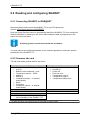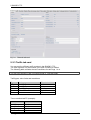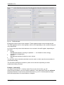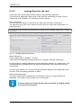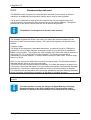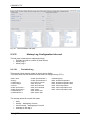
1
Please Note:
The Hydrometer type SCYLAR INT8 and the
Siemens SITRANS FUE950 (7ME348 ones) are
identically!
Siemens A/S
Flow Instruments
Nordborg, 11.04.2012
IZAR@SET
i
User Manual
Version: 1.1
Date of issue: 28.03.2012
Copyright: 2011 HYDROMETER / Ansbach / Germany
IZAR@SET
ii
Contents
Contents
1
2
3
4
5
6
7
8
9
Introduction .................................................................................................................... 5
1.1
Task of software..................................................................................................... 5
1.2
System requirements ............................................................................................. 5
1.3
Devices .................................................................................................................. 5
1.4
About the User Manual .......................................................................................... 6
1.5
Customer support .................................................................................................. 7
Installation...................................................................................................................... 8
Starting IZAR@SET ......................................................................................................10
3.1
Starting the software and logging in ......................................................................10
3.2
Authorization levels...............................................................................................10
Connecting devices to IZAR@SET................................................................................12
4.1
Setting up a Bluetooth connection.........................................................................12
4.2
Setting up a Bluetooth connection with USB Bluetooth stick .................................15
4.3
Setting up a connection with serial opto head .......................................................17
4.4
User preferences ..................................................................................................19
4.4.1 Device configuration..........................................................................................19
4.4.2 Help ..................................................................................................................21
4.4.3 Communication .................................................................................................23
4.4.4 Security.............................................................................................................23
4.4.5 Language setting...............................................................................................25
Setting up IZAR@SET ..................................................................................................26
5.1
IZAR@SET user interface.....................................................................................26
5.2
Menu bar...............................................................................................................26
5.3
Toolbar .................................................................................................................28
5.4
Tab cards..............................................................................................................30
5.4.1 Display of tab cards...........................................................................................30
5.4.2 Example of “common” tab card from SHARKY 775 ...........................................31
Configuring devices.......................................................................................................32
6.1
Input aids ..............................................................................................................32
6.2
Configuring a device .............................................................................................32
6.3
Working with profiles.............................................................................................34
6.3.1 Creating a profile...............................................................................................34
6.3.2 Apply profile ......................................................................................................34
6.3.3 Delete profile.....................................................................................................35
6.4
Changing devices .................................................................................................35
6.5
Ending configuration .............................................................................................35
Help ..............................................................................................................................36
Legal notices .................................................................................................................37
8.1
Licence contract....................................................................................................37
8.2
Third-party licences...............................................................................................40
SHARKY 775 ................................................................................................................41
9.1
Features of SHARKY 775 .....................................................................................41
9.1.1 Calculator..........................................................................................................41
9.2
Reading and configuring SHARKY........................................................................42
9.2.1 Connecting SHARKY to IZAR@SET .................................................................42
9.2.2 Common tab card..............................................................................................42
9.2.3 Tariffs tab card ..................................................................................................43
9.2.4 Due date tab card..............................................................................................47
9.2.5 Display tab card ................................................................................................48
9.2.6 Maximum and Average Values tab card............................................................50
9.2.7 Pulse Output tab card .......................................................................................52
9.2.8 Pulse Input tab card ..........................................................................................52
IZAR@SET
iii
Contents
9.2.9 Analogue Output tab card .................................................................................53
9.2.10
Leakage Detection tab card...........................................................................54
9.2.11
Communication tab card ...............................................................................55
9.2.12
History Log Configuration tab card ................................................................56
9.2.13
Periodical Log tab card..................................................................................59
9.2.14
History Log 1 and 2 tab card .........................................................................60
9.2.15
Error Log tab card .........................................................................................61
9.2.16
Calibration tab card .......................................................................................62
IZAR@SET
iv
1 Introduction
1 Introduction
1.1 Task of software
IZAR@SET is a PC application for the configuration of complex devices like heat and water
meters.
You can also use it to read measured values and data logs, analyse systems and save
counter logs.
1.2 System requirements
The following requirements are recommended for normal use. Depending on the application,
the use of other configurations may be possible or necessary, especially regarding data
security and the required functions.
Operating systems supported:
• Microsoft Windows XP with Service Pack 2
• Microsoft Windows Vista
• Microsoft Windows 7, 32-bit system
Recommended hardware:
• CPU with minimum clock frequency of 2 GHz
• 1024 MB main memory
• 100 MB of available hard disk space
• CD-ROM drive
• Network card for TCP/IP protocol
• Screen with minimum resolution of 1024 x 768 pixels
• Bluetooth interface (internal or external as USB stick) with Widcomm, Microsoft or
BlueSoleil stack
Optional hardware components:
• Serial interface (for serial opto head)
If problems occur with your built-in or external Bluetooth device, we recommend using one of
the following devices:
• Fujitsu Siemens USB Bluetooth stick V2.1 for Windows XP
• Fujitsu Siemens USB Bluetooth stick V2.0 for Windows 7
1.3 Devices
The following devices can currently be configured with IZAR@SET:
• SHARKY 775
• SCYLAR INT 8
You must also use the Installation and Operating Guide for configuring these devices. This
contains detailed explanations of the device functions.
Only a limited number of parameters can be changed in the Standard mode of the program.
To set other device parameters, the system must be equipped with a dongle with the
IZAR@SET
5
1 Introduction
necessary activation licence. More about this can be found in Section 3.2 Authorization
levels.
Setting the parameters is explained in more detail in Section 5.4 Tab cards and Section 6
Configuring devices.
1.4 About the User Manual
This User Manual describes how to set up and use the IZAR@SET software. Please read
the User Manual carefully before starting to work with the software.
Always have the Operating Guide for your meter available.
Various font formats are used to make it easier for you to find your way around the User
Manual:
Type of
information
Commands
Formatting
Example
italics
Command Save profile
(Safety)
Information
bold
NOTE: It is not possible to change the device
during the configuration process.
References to
sections
Functions in
Expert mode
underlined
More about this can be found in Section 3.2
Authorization levels.
framed by
dotted line
This function is only available in Expert mode.
Functions in Test
Lab mode
Descriptions
Instructions
framed
This function is only available in Test Lab mode.
normal
Please read the User Manual carefully before
starting to work with the software.
ATTENTION:
Damage to equipment or data loss is possible.
Observe the causes and countermeasures.
NOTE:
Additional information to simplify using the
software.
Symbols used:
IZAR@SET
6
1 Introduction
1.5 Customer support
You can contact our Customer Support team as follows:
HYDROMETER GmbH
Industriestraße 13
91522 Ansbach
Germany
IZAR@SET
Phone: +49 981 1806 0
Fax: +49 981 1806 605
E-mail: [email protected]
Internet: www.hydrometer.de
7
2 Installation
2 Installation
The installation program for the IZAR@SET software can be downloaded from the Diehl /
Hydrometer home page.
Proceed as follows to download:
Go to our home page at www.diehl.com and click the Products & Solutions register on the
left. Then click Product Download. The Product Download section opens with its threecolumn overview.
Select the desired partner in the left column: Hydrometer.
Select the product heading in the centre column: Metering Systems. This heading opens.
Now select the product: IZAR@SET.
Select the category in the right column: Software.
The software (*.exe) is available below this overview. Click the software title (light green) to
start the download.
Fig. 1:
Download section of home page
The installation is carried out in the DIEHL Metering program directory on your local hard
disk.
IZAR@SET
8
2 Installation
NOTE
IZAR@SET
This software enables you to run the application in Standard mode, in
which you can only read data and change a few parameters. To run the
application in Expert mode or Test Lab mode, you need a dongle with
the relevant authorization, see Section 3.2 Authorization levels.
9
3 Starting IZAR@SET
3 Starting IZAR@SET
3.1 Starting the software and logging in
When starting the program from the Start menu, you must log in. The user name is: admin,
the password is radio.
Fig. 2:
Login
3.2 Authorization levels
In Standard mode you can read the meter, read logs and save logs as csv files, but you can
only change a few items of data.
For the Expert mode, you need a USB dongle with the respective authorization. Depending
on the write protection of the device, you can change parameters in this mode, but not data
relevant to verification.
To use the Test Lab mode, test centres need a special USB dongle with more functions
than the dongle for Expert mode. In Test Lab mode you can change fundamental device
settings, including verification data.
IZAR@SET
10
3 Starting IZAR@SET
You can purchase the authorization for Expert mode or Test Lab mode from Hydrometer,
who will then provide you with the necessary dongle. Connect the dongle to your PC/laptop
and restart the software. All functions of the relevant mode will then be available for your use.
NOTE
IZAR@SET
Your dongle must always be connected for working in one of the two
advanced modes. This is necessary to provide access to the advanced
functions.
11
4 Connecting devices to IZAR@SET
4 Connecting devices to IZAR@SET
Read the separate Operating Guide for the device before reading it with
IZAR@SET.
NOTE
IZAR@SET can read devices and write configurations to devices using a Bluetooth opto
head or a serial interface.
NOTE
The Bluetooth opto head is equipped with an internal battery. Keep the
battery sufficiently charged.
If you have a PC or laptop with a Bluetooth interface, follow the instructions in Section 4.1
Setting up a Bluetooth connection.
If your PC or Laptop is NOT equipped with a Bluetooth interface, follow the instructions in
Section 4.2 Setting up a Bluetooth connection with USB Bluetooth stick.
If you use a serial opto head to connect the device and PC/laptop, follow the instructions in
Section 4.3 Setting up a connection with serial opto head.
4.1 Setting up a Bluetooth connection
If you have a PC or laptop with a Bluetooth interface, set up the connection between the
software and device as follows:
1.
Start the IZAR@SET software and log in (see Section 3.1 Starting the software and
logging in).
The main dialogue window appears.
IZAR@SET
12
4 Connecting devices to IZAR@SET
Fig. 3:
Main dialogue window
2.
Switch on the opto head by sliding the control to ON.
3.
Place the opto head on the optical interface of the meter.
Fig. 4:
4.
Opto head on system device and switched on
Click the User Preferences symbol. Click Communication in the menu on the left.
Select the second option and set the desired COM interface. The COM interface for the
Bluetooth settings is assigned by the operating system or selected (Control Panel > Set
IZAR@SET
13
4 Connecting devices to IZAR@SET
up new Bluetooth connection).
Confirm and close the User Preferences by clicking OK.
Fig. 5:
Communication
The Bluetooth connection is set up. The blue lamp on the opto head lights if set-up is
successful.
Fig. 6:
5.
Bluetooth connection complete
Click the Optical Device symbol to automatically identify the device to be configured.
While the software is scanning for the device and reading the data, a progress bar in
the status line shows the status.
IZAR@SET
14
4 Connecting devices to IZAR@SET
A running process can be aborted with the red button (next to the
progress bar).
NOTE
You then pass to the configuration phase. A user interface specially for the device appears
for setting the specific parameters of the device.
Fig. 7:
User interface
4.2 Setting up a Bluetooth connection with USB
Bluetooth stick
If your PC or laptop is not equipped with its own Bluetooth interface, use a USB Bluetooth
stick (see Section 1.2 System requirements).
1.
Insert this USB Bluetooth stick in a free USB slot of your PC or laptop.
Carry out the following if using the stick for the first time:
Install the driver software for the USB Bluetooth stick (takes place automatically or use
the enclosed CD).
Add a new wireless device to your PC or laptop. Do this by selecting the Bluetooth
Devices folder in the Control Panel of your PC/laptop. Click the Add Wireless Device
function and follow the instructions that appear.
IZAR@SET
15
4 Connecting devices to IZAR@SET
Make a note of the Bluetooth address of the opto head for the setting in
IZAR@SET (the IP address can be found under the properties of the
opto head)!
NOTE
2.
Start the IZAR@SET software and log in (see Section 3.1 Starting the software and
logging in).
The main dialogue window appears.
3.
Carry out steps 2 to 6 as described in Section 4.1 Setting up a Bluetooth connection.
Click the User Preferences symbol. Click Communication in the menu on the left.
Select the first option and enter the MAC address of the opto head. Confirm and close
the User Preferences by clicking OK.
Fig. 8:
Communication
IZAR@SET
16
4 Connecting devices to IZAR@SET
4.3 Setting up a connection with serial opto head
If you wish to set up the connection between software and device over a serial interface,
proceed as follows:
Only IRDA opto heads are supported.
ATTENTION
1.
2.
3.
Start the IZAR@SET software and log in (see Section 3.1 Starting the software and
logging in).
The main dialogue window appears.
Connect the serial opto head to a serial port of your PC/laptop.
Carry out steps 2 to 6 as described in Section 4.1 Setting up a Bluetooth connection.
Click the User Preferences symbol. Click Communication in the menu on the left.
Select the third option and set the desired interface. Confirm and close the User
Preferences by clicking OK.
IZAR@SET
17
4 Connecting devices to IZAR@SET
Fig. 9:
Communication
IZAR@SET
18
4 Connecting devices to IZAR@SET
4.4 User preferences
By selecting the User Preferences menu option in the main dialogue window you access the
dialogues for the general application settings. You can set relevant conditions for the
application here.
4.4.1 Device configuration
The functions in the Device Configuration dialogue are not available for all devices or all
parameters.
The functions in the Device Configuration dialogue are only available in Expert mode.
Allowing writing of devices without prior reading
It is sometimes necessary to configure a number of identical devices with the same setting.
To speed up processing, this configuration should be possible without prior reading (see
Section 6.3 Working with profiles).
Allowing writing of devices if invalid parameter states exist
It is not possible to write a device if errors still exist in the fields of individual tab cards. This
function explicitly allows writing despite the existence of errors, but you are notified of the
error (see Section 6.1 Input aids).
IZAR@SET
19
4 Connecting devices to IZAR@SET
Fig. 10: User Preferences Dialogue > Device Configuration
IZAR@SET
20
4 Connecting devices to IZAR@SET
4.4.2 Help
The Help dialogue can be used to define the display of the help texts. You can choose
whether the help appears in the dynamic help view or is opened in a web browser.
Fig. 11: User Preferences Dialogue > Help
IZAR@SET
21
4 Connecting devices to IZAR@SET
Fig. 12: User Preferences Dialogue > Help
Fig. 13: User Preferences Dialogue > Help, Add Info Centre
IZAR@SET
22
4 Connecting devices to IZAR@SET
4.4.3 Communication
The Communication dialogue is for specifying how IZAR@SET communicates with the
devices connected to it. The settings shown below are possible:
Detailed information on connecting devices to the software can be found in the preceding
Sections 4.1 Setting up a Bluetooth connection, 4.2 Setting up a Bluetooth connection with
USB Bluetooth stick and 4.3 Setting up a connection with serial opto head.
•
Bluetooth opto head (IZAR OH BT):
Enter the Bluetooth address (printed on the opto head).
NOTE
This option only functions if a Bluetooth stick from Microsoft,
Broadcom/Widcomm or Bluesoleil is installed in the system. The
following option must be used for other Bluetooth stacks (e.g. Toshiba
Bluetooth software).
•
Bluetooth opto head (IZAR OH BT) via serial: Enter a virtual COM port to which the
Bluetooth opto head is connected. Configure the virtual COM port in accordance with
the User Guide for your Bluetooth stick.
•
Serial opto head: Enter the COM port of the serial opto head
4.4.4 Security
The Security dialogue is used to define whether IZAR@SET is to change the password
and/or radio key on the device during device configuration.
You can only change these settings in Expert mode.
Keep password
The device radio key is not changed.
Set radio key to default
If activated, the device is rewritten with the default radio key.
Set own radio key
If activated, the device is rewritten with the radio key entered.
Note that the radio receivers must also have the corresponding
radio key.
ATTENTION
IZAR@SET
23
4 Connecting devices to IZAR@SET
Fig. 14: User Preferences Dialogue > Security
IZAR@SET
24
4 Connecting devices to IZAR@SET
4.4.5 Language setting
The Language Setting dialogue is for setting the language in which dialogues and texts are
displayed in IZAR@SET. The language setting also changes the display of the date or
numerical values.
The following languages are possible:
• German
• English
• French
• Hungarian
• Polish
After changing the language, IZAR@SET must be restarted for the
change to become effective.
NOTE
Fig. 15: User Preferences Dialogue > Language Setting
IZAR@SET
25
5 Setting up IZAR@SET
5 Setting up IZAR@SET
5.1 IZAR@SET user interface
The figure below shows the basic design of the user interface and the following sections
provide more information about the various parts.
1
2
3
Fig. 16: User interface
Legend:
1 Menu bar
2 Toolbar
3 Configuration dialogues (arranged as tab cards)
5.2 Menu bar
The Optical Devices button in the main menu of the program is used to read the device
connected.
The following commands are then available in the menu bar:
IZAR@SET
26
5 Setting up IZAR@SET
Fig. 17: Commands in the menu bar
Back – opens the main menu
Exit – closes the program
Read – the device is read again (only the current values are shown, the logs are called up
via the Commands menu)
Write – writes changes to the device
Read – reads the various logs
• Error log
• Periodical log
• History log 1
• History log 2
The associated tab cards are filled.
Export – of the various logs
Writes the selected log (see above) as csv file to the “Data” folder in the program directory
C:\Programs\Diehl Metering\IZAR_SET\IZAR.
The file name consists of the production number of the device, the name of the log and the
time of saving.
Create diagnostic file (if error occurs)
This command creates an encrypted diagnostic file, which can be evaluated by Customer
Support at Hydrometer if an error occurs. In this case, as much data as possible is read from
the meter, which means this operation can take a very long time. You should therefore only
use this command in the event of an error.
IZAR@SET
27
5 Setting up IZAR@SET
Clear:
The device must allow the respective clear function.
NOTE
The clear function is only available in Expert mode and Test Lab mode.
•
•
•
•
•
Clear operating hours
Clear error time
Reset leakage alarms
Clear error log
Reset the device and all logs
Profiles:
• Apply profile:
Here you call up a stored profile of a device configuration. The settings from this
profile are applied to the current device.
• Save profile:
You transfer the changes made to the device settings to the current profile. A profile
must be available and selected.
• Save profile as:
You transfer the changes made to the device settings to a new profile.
• Delete profile:
You delete a selected profile.
Detailed information can be found in Section 6.3 Working with profiles.
5.3 Toolbar
You can use the symbols in this bar to read parameters, change parameters for the device,
and create, delete and apply profiles to the device.
NOTE
Your changes are not saved in the device until you execute the Write
command in the menu. You can check this by reading the current
parameters from the device with the Read command. More information
can be found in Section 6 Configuring devices.
The following commands are available in the toolbar:
Fig. 18: Toolbar
IZAR@SET
28
5 Setting up IZAR@SET
Back – opens the main menu
Read – the device is read again (only the current values are shown, the logs are called up
via the Commands menu)
Write – writes changes to the device
Profiles: see Section 5.2 Menu bar
IZAR@SET
29
5 Setting up IZAR@SET
5.4 Tab cards
5.4.1 Display of tab cards
Related data in the tab cards can be grouped with a frame. The data groups are arranged
according to window size.
The following figure shows you examples of the data groups.
Fig. 19: Grouping of data
A tab card is displayed by clicking its tab. The tab of the active tab card is highlighted.
The tab cards can be opened in any order. You can use the arrow keys to the right of the
tabs to change to any tab cards not displayed in the window.
The device data are distributed to and shown on various tab cards. You can carry out
calibration of your device in the individual tab cards.
You can configure your device for other tab cards, e.g. set the tariff settings and set days,
define maximum and mean values, calibrate leakage detection or evaluate stored data.
IZAR@SET
30
5 Setting up IZAR@SET
5.4.2 Example of “common” tab card from SHARKY 775
The tab card shows general data for the device.
The data are combined in logical groups:
• Device – full identification and device designation
• Values – meter counts
• Date and time – can be synchronized to the PC in Expert mode
• Addresses – primary and secondary addresses of the device can be changed
• Device status – shows the protection level and current error messages of the device
You can change the date, time and addresses of the device.
Fig. 20: Example of “common” tab card from SHARKY 775
IZAR@SET
31
6 Configuring devices
6 Configuring devices
6.1 Input aids
The following input aids are provided to simplify entering values:
Dates are entered using a calendar display. This opens when you click the button on the
right of a date field. You can also enter a date directly in the input field.
In addition, discrete values are entered using selection fields that only offer you a choice of
valid values.
Lists (right-left lists) are available for you to assign mass data. Here the available fields are
shown in the left column and the fields already selected in the right column.
Multi-line windows are used to display log data. Pop-up windows appear if questions or
messages must be taken into account when changing data.
Many parameters have side effects.
For example, the parameter that defines the tariff mode influences another field such as the
tariff limit. These relationships are indicated in the user interface by a yellow background to
highlight parameters that are changed when another parameter is changed.
Invalid inputs are indicated in a similar way. If an input field contains an invalid value or its
value becomes invalid because another parameter has been changed, the background of the
invalid parameter is marked red.
6.2 Configuring a device
When you order a device, you will be asked for your required parameters and these will
already be set on delivery. If you have not provided any information with your order, the
device will be supplied with the default settings.
NOTE
Users in Standard mode can only change a limited number of values.
More parameters can only be changed if the system is equipped with a
dongle with the relevant licence activated.
To access device configuration, click Read in the main dialogue window. The device is first
read and its current values shown in the user interface.
You can then start changing the device parameters.
You can change as many parameters as you wish, as the changes initially have no effect on
the device, but are only made in IZAR@SET. Every change is checked for valid inputs, so
invalid inputs or the consequences for dependent parameters are shown immediately.
Your changes are not saved in the device until you execute the Write command. You can
read the current device values again with the Read command. Unwritten changes to
parameters are overwritten and set to the values of the device (see Section 6.3.2 Apply
profile).
IZAR@SET
32
6 Configuring devices
NOTE
IZAR@SET
Ensure that the opto head remains connected to the device during the
configuration and that the opto head is switched on or connected to the
PC.
33
6 Configuring devices
6.3 Working with profiles
To configure many devices with the same settings, you can save settings for each type of
device as profiles. A profile comprises only the changed parameters.
6.3.1 Creating a profile
1.
To create a profile, first read the device.
2.
Carry out any changes required for the profile.
3.
Execute the command Save profile as. Only the changes made are logged and saved
as a profile.
4.
You can also extend a profile retrospectively. This is done by making the device
changes necessary for the extension and saving these under the existing profile.
The profile is saved in the software. It is not transportable, but only
available via the software.
NOTE
6.3.2 Apply profile
1.
First read the device then open the Apply profile command in the menu bar.
2.
3.
Select one of the stored profiles. The changes are made in the IZAR@SET software.
Press the Write button to save the changes.
4.
Read the device again to make sure the changes have been saved successfully.
If you have selected the command Device configuration > Allow device writing without
prior reading under User Preferences, a profile can be transferred to the connected
device without prior reading. At least one device must be read previously, however,
because you can only execute the Profile command from the device view.
Profiles can only be applied to devices of the same generation.
NOTE
IZAR@SET
34
6 Configuring devices
6.3.3 Delete profile
1.
2.
Use this command to delete a profile you no longer require.
Select the profile to be deleted (if several profiles exist) and confirm the deletion by
clicking OK.
6.4 Changing devices
It is not possible to change the device during the configuration process.
NOTE
To configure another device, first finish the current configuration process completely and
return to the main dialogue of IZAR@SET.
Connect a new device. Start a new configuration using the command Optical Reading for
device detection.
6.5 Ending configuration
When you have made all the required configurations, close the configuration process
completely by returning to the main dialogue of IZAR@SET. Exit the program using the
menu File > Exit.
IZAR@SET
35
7 Help
7 Help
Selecting the Help menu option in the main dialogue window gives you access to the User
Manual and other information.
Fig. 21: Help menu
Selecting the About menu option shows the licence information.
Fig. 22: Information about IZAR@SET
Help opens the User Manual.
IZAR@SET
36
8 Legal notices
8 Legal notices
© HYDROMETER GmbH Ansbach / Germany / 2000 – 2008
The name IZAR@SET, the IZAR@SET software and this manual are protected by copyright.
Their utilization in any way whatsoever is prohibited without the consent of the publisher.
This particularly applies to reproduction, translation, microfilming and storage and processing
in electronic systems.
The registered trademarks, trade names and utility names used in this manual are covered
by the relevant protection regulations, even if this is not specifically indicated.
The IZAR@SET software and this documentation have been carefully prepared and checked
for freedom from errors, but the possibility of undetected errors cannot be completely
excluded. HYDROMETER accepts no liability for damage or consequential damage
occurring in connection with this product, the use of this product or the inability to use this
product. No liability whatsoever is accepted for operational interruptions, production
interruptions, injury to persons, loss of data or information or any other financial loss. Liability
is restricted in principle to the amount paid for this product.
8.1 Licence contract
By opening the seal of the enclosed CD, the customer accepts the conditions of the following
software transfer and licence contract as binding, unless he returns the CD undamaged and
uncopied together with all manuals etc. within 2 weeks of the date of purchase together with
the original dated purchase contract to the following address (date of dispatch applies):
Diehl Metering
Industriestraße 13
91522 Ansbach – Germany
In this case, the customer shall receive a refund of any payments already made, less a
processing fee of € 40, which he must otherwise pay.
Art. 1 Subject of this contract
The customer acquires the following on conclusion of this contract and payment of the full
purchase price:
a) the ownership of the hardware sold to him (CDs and manuals),
b) a non-exclusive licence to use the acquired software in the current version at the
time of acquisition, including any official updates/releases published by the LICENSOR
up to this time. The customer receives this licence provisionally on taking possession
of the software until a possible default on payment. In the event of default on payment,
the licence is automatically cancelled until the customer settles any outstanding
payments.
IZAR@SET
37
8 Legal notices
Art. 2 Scope of licence; assignment of possible shares in copyrights to the
LICENSOR
(1) The customer may only use the software acquired from the LICENSOR for administration
of the agreed number of metering devices. He shall be entitled to make one back-up copy.
Any changes, further development or other modification of the software by the customer are
strictly prohibited, irrespective of whether these are carried out by the customer himself or by
third parties. Any such attempt immediately terminates the relevant right to use the software
and excludes the liability of the LICENSOR for any resulting or possibly resulting defects.
The software may not be sublicensed and/or sold to third parties except with the explicit prior
written consent of the LICENSOR. The decision on whether or not to grant such consent
shall be at the sole discretion of the LICENSOR.
(2) Any attempt to reengineer, decompile or deassemble the software is strictly prohibited.
The source code remains the sole property of the LICENSOR at all times.
(3) All copyrights to ideas and problem solutions developed jointly by the LICENSOR and the
customer or the sole authority to exercise such rights rest completely with the LICENSOR.
(4) A copyright notice is installed in the software. The customer may use or sell the software
only with this copyright notice intact. This notice shall also be left on or attached to copies of
the software. Neither the copyright notice nor the registration number of the software may be
changed or removed in any way whatsoever.
Art. 3 Liability for defects in the software supplied
(1) The LICENSOR is liable for ensuring that the software supplied is capable of processing
the consumption data fed into it in a form suitable for billing. This is described in more detail
in the enclosed manual. The LICENSOR is excluded from any liability for damage caused by
avoidable incorrect operation of the software or its use in conjunction with other software not
explicitly authorized by the LICENSOR or by an unauthorized attempt by the customer to
modify the acquired software or adapt it to a subsequently modified working environment. If
the customer has used such unauthorized software or has attempted to make such a change
or adaptation, it is incumbent on the customer to prove that such action was not one of the
causes of the occurrence of possible defects.
(2) If certain individual functions do not work in certain constellations exactly as described in
the manual or as expected under the circumstances, this shall not be deemed to constitute a
defect. On the contrary, the program shall be considered as free of defects regarding a
certain function provided the promised function in individual cases is provided in a different
but not substantially less convenient way than would actually be expected. (Example: In
individual cases, the program is unable to show a certain response/trend graphically, but in a
statistical list in a barely less vivid way).
(3) If a defect exists, the customer shall notify its detection to the LICENSOR in writing
without delay and as specifically as possible. The LICENSOR shall then have the opportunity
to undertake maximum 2 attempts to rectify the defect, with the option of either supplying a
certain new module or by repairing the defect. Such repair can be – and is normally –
achieved by supplying a suitable corrective release, which is loaded into the customer’s
software. The customer may not reject such a new release because in addition to the
required repair it contains other changes to the software that he is not interested in or does
not want for other reasons. On the contrary, he must accept this release provided it does not
substantially adversely affect his original purpose or the other unwanted changes cannot be
excluded from transmission to the customer at the same time without great expense for the
IZAR@SET
38
8 Legal notices
LICENSOR. If the LICENSOR’S second attempt to rectify the defect fails, the customer may
either reduce the purchase price or cancel the contract and possibly claim damages.
(4) The LICENSOR is also liable to the customer for ensuring that the use of the software
does not violate third parties’ intellectual property rights reported in or for Germany at the
time of handing over the software to the customer and at this time either already published or
certainly available with suitable research such that the LICENSOR either did discover or
should have discovered these intellectual property rights during a standard inquiry into the
existence of intellectual property rights. If legal action is threatened or taken by third parties
due to alleged violation of the intellectual property rights of third parties by the software, the
customer shall notify the LICENSOR without delay. In this case, the LICENSOR shall
indemnify the customer for all financial disadvantages arising out of such action, but only if
a) the customer notifies the LICENSOR of the assertion of the claim by the third party
without delay (within one week), and if the customer
b) also grants the LICENSOR the full authority to conduct any process in its own name
for the customer (representative action).
Art. 4 General liability of LICENSOR
The liability of the LICENSOR for damages for any legal reason whatsoever is limited to
injuries or death of persons and material loss. Any liability for damage of a purely financial
nature, particularly the loss of data or claims for damages of customers due to software
defects, is limited to the maximum amount of the purchase price paid to the LICENSOR by
the customer for the new software provided the LICENSOR can prove that the damage was
caused only by ordinary negligence on the part of himself or his vicarious agents. The period
for asserting claims for liability for defects is 12 months
Art. 5 Purchase price and default on payment
The purchase price is based on the version of the order catalogue valid at the time of
receiving the order. However, only the price confirmed to the customer by the LICENSOR in
writing shall be final and binding. Interest at 8 % above the respective base rate of the
European Central Bank (ECB) shall be payable in the event of default on payment.
Art. 6 Confidentiality
Neither party shall disclose information to third parties about the mutual business relationship
or any information of a confidential nature about the other party obtained in the course of this
business relationship; furthermore, both parties shall use such information exclusively for the
purpose of fulfilling this agreement and not for their own purposes, shall only make this
information accessible to their employees who need it for fulfilling this particular purpose, and
who, either through their employment contract or through the conclusion of a relevant
supplementary agreement, are obliged to maintain secrecy in the same way as the parties
themselves through this agreement. The customary exceptions apply (verifiable previous
knowledge etc.). Publications by one of the two parties, in which the use and/or provision of
SOFTWARE by the respective other party is mentioned in a not insignificant way and named,
require prior written approval by this other party.
IZAR@SET
39
8 Legal notices
Art. 7 Written form
Changes to this contract, including changes to this written form clause, subsidiary
agreements or amendments and supplements shall be made in writing.
Art. 8 Applicable law and place of jurisdiction
(1) This contract is governed by German law, excluding UN Sales Law.
(2) The place of jurisdiction, including for action against the LICENSOR, is Ansbach. The
LICENSOR may alternatively file proceedings at any other legally provided places of
jurisdiction.
8.2 Third-party licences
Hydrometer is obliged to inform you that the software you have purchased has not been
created exclusively by Hydrometer, but in many places draws on software – open source
components – available free on the Internet or incorporates these components in this
software package. The transfer of such components is free of charge, but it is mandatory to
pass on the respective licence conditions on a 1:1 basis to the customer. The respective
manufacturers have apparently not taken into account that there are other countries as well
as the USA and that it cannot be assumed that English is spoken fluently all over the world.
In addition, it is difficult or impossible for users to identify whether or not parts of the
individual software packages are such a component or usable separately. We therefore save
you and us the burden of printing all these conditions individually for you here and only
provide the respective Internet link, where you can download these conditions. Software
package licences:
•
•
•
•
•
•
•
•
•
•
•
•
Eclipse Rich Client Platform Eclipse Public License
Bouncycastle Bouncycastle License
Apache Jakarta ORO Apache License, Version 2.0
Apache Commons Net Apache License, Version 2.0
Apache Commons Codec Apache License, Version 2.0
Apache Derby Apache License, Version 2.0
Apache log4j Apache License, Version 2.0
BlueCove Apache License, Version 2.0
Avetana Bluetooth Avetana License
RxTx LGPL 2.1
Micrsosoft Active Sync Microsoft ActiveSync License
NSIS Installer NSIS License
We assume that the various manufacturers or owners of the copyrights to the above-named
open source components agree to this procedure as the only practicable solution, as
otherwise their main aim of the widest possible distribution of their software could not be
achieved to the same extent.
IZAR@SET
40
9 SHARKY 775
9 SHARKY 775
9.1 Features of SHARKY 775
NOTE
Only the most important information is listed here. All other information
concerning installation, communication modules etc. can be obtained
from the separate Operating Guide for SHARKY 775.
The SHARKY 775 ultrasonic energy meter is available in three variants: heat meter, heat
meter with cooling tariff, and cooling meter.
The IZAR@SET display may vary according to the variant used.
SHARKY 775 is used for measuring thermal energy, flow rate and temperatures and has the
option of reporting flow rate deviations (leaks).
SHARKY 775 operates in the temperature range from 5..90/130/150 °C, depending on
variant and nominal size.
9.1.1 Calculator
The following figure shows the design of the integrator. More detailed information is available
in the separate Operating Guide for SHARKY 775.
8-digits LC display with
units and symbols
Button for display control
• short keypress (< 3 sec.)
> change in the loop
• long keypress (> 3 sec.)
> change in the loop
Fig. 23: Design of integrator in SHARKY 775
IZAR@SET
Optical interface (standard)
ZVEI (M-Bus protocol)
41
9 SHARKY 775
9.2 Reading and configuring SHARKY
9.2.1 Connecting SHARKY to IZAR@SET
Start the software and connect the SHARKY 775 to your PC/laptop (see
Section 4 Connecting devices to IZAR@SET).
Click the Optical Devices button to automatically identify the SHARKY 775 to be configured.
While the software is scanning for the device and reading the data, a progress bar in the
status line shows the status.
A running process can be aborted with the red button.
NOTE
You then pass to the configuration phase. A user interface appears for setting the specific
parameters of the SHARKY 775.
9.2.2 Common tab card
The tab card shows general data for the device.
Device
•
•
•
•
•
•
•
Device name – SHARKY type 775
qp m³/h
Medium to be measured – heat
Temperature sensor – Pt500
Module 1
Module 2
Installation location – is entered
automatically
• Radio
• Frequency
• Production number – is entered
automatically
Date and time
• Entered automatically
Device status
• Shows the protection level and current
error messages of the SHARKY 775
Values (current meter counts)
• Energy kW/h
• Volume m³
• Power kW
• Flow rate m³/h
• Temperature (hot) °C
• Temperature (cold) °C
• Temperature difference K
Addresses
• Entered automatically
The date and time of the device can be changed in Expert mode.
IZAR@SET
42
9 SHARKY 775
Fig. 24: General tab card
9.2.3 Tariffs tab card
You can set four different tariff counters in the SHARKY 775.
The tariff registers only accumulate if the tariff condition is fulfilled.
The following table contains the tariff conditions for tariff logs 1 to 4.
You can only set tariff 1 and 2 in Expert mode or Test Lab mode.
Tariff types, value limits and resolutions
Type
∆T
Tr,Tf
P
Q
Z
Limit
1 .. 255 °C
1 .. 255 °C
1 .. 255 kW
0.1 .. 25.5 m³/h
Resolution limit
1K
1K
1 kW
0.1 m³/h
15 minutes
Time-controlled tariff Z (example):
Day
Mon-Fri on
Mon-Fri off
Sat-Sun on
Sat-Sun off
IZAR@SET
Time
06:00
22:00
06:00
22:00
43
9 SHARKY 775
Fig. 25: Tariffs tab card
Energy and volume are the main registers. These registers always count the data as well.
The tariff registers are four extra registers, which count depending on the condition being met
in the Mode field.
In Count mode they select which data are to be counted in the tariff register, depending on
the mode:
1.
Energy
Distinguishes between counting in quadrant 1 ... 4 or forward or return energy
(temperature-independent)
2.
Volume
Distinguishes between forward or return volume
3.
Time
You can also select externally controlled as count mode, in which case the accumulation is
controlled externally.
The necessary settings are marked in yellow on the tab card, depending on which
mode/count mode you select:
Example 1 (heat tariff):
You select count tariff dT >= limit as mode. Enter a value for the limit, e.g. 30 °.
Select Energy Quadrant 1 as count mode (quadrant 1 is the heat tariff). Enter the minimum
temperature (sensor in the hot line) for this heat tariff, e.g. 20 °C. If the forward flow drops
below this temperature, the accumulation is stopped.
IZAR@SET
44
9 SHARKY 775
Fig. 26: Example 1 – Set data tariff
Example 2 (cooling tariff):
You select count tariff dT <= limit as mode. Enter a number to mark the limit, typically 0K for
cooling tariff.
Select Energy Quadrant 4 as count mode (quadrant 4 is the cooling tariff). Enter the
maximum temperature (sensor in hot line) for this tariff, e.g. 20 °C.
This prevents measurement at the automatically set heat temperature of > 20 °C with the
system switched off.
Fig. 27: Example 2 – Set data tariff
IZAR@SET
45
9 SHARKY 775
Example 3:
You select the time controlled time tariff as mode. Enter the times in which the data are to be
accumulated under Tariff 1 and 3 time-controlled in the bottom section of the display.
Select Energy of the desired quadrant as count mode.
Fig. 28: Example 3 – Set time tariff
Example 4:
Select externally controlled as mode.
As count mode select the pulse input that is to externally control the data accumulation.
Fig. 29: Example 4 – externally controlled data accumulation
The setting "low" or "high" after the definition of the external port defines the respective input
level for active accumulation.
The "Forward Energy" and "Return Energy" count modes work with a real sensor
temperature in the hot line, but with a permanently programmed cooling temperature (exworks setting 0 °C).
IZAR@SET
46
9 SHARKY 775
9.2.4 Due date tab card
A set day is a copy of the relevant accumulating register at the set time.
The default settings for the set days are 1.6 and 31.12. The value group Set Day 1/2 current
values shows you the values of the current set day, the value group Set Day 1/2 last values
shows you the values of the previous set day.
You can set two different set days. You can choose set days between daily, weekly (stating
the weekday), twice monthly, monthly or annually. The current and last set day values are
shown for these.
NOTE
The set day values always refer to the beginning of the day, i.e. to
0:00:00 on the day indicated.
This also makes a set day of 29.2 possible.
Fig. 30: Set Days tab card
IZAR@SET
47
9 SHARKY 775
9.2.5 Display tab card
The SHARKY 775 is supplied ex works with a basic loop structure as default setting.
You can change the loops in Expert mode.
You can define up to six different loops for the device display. A list of all the fields available
is displayed for each loop, from which you can select the desired fields.
Loop 1 and loop 3 can not be disabled or enabled, they are enabled at the factory. You can
change loop 1 up to loop 5 in the order of appearance in each loop and add or remove
values. The appearance of loop 6 cannot be changed.
The following conditions apply:
The total number of selectable fields for all loops is limited to 60 fields. If more data are
selected, they are not accepted for the respective loop.
Loop 1 cannot be deactivated.
NOTE
The verified register must always be in the first position.
The following fields must be defined in a desired loop of the display. These fields cannot be
removed from a loop until they have been added to another loop.
• Installation position
• Error status
• Display test
• Software version : OUT4 (optical test pulses)
NOTE
IZAR@SET
The desired fields are activated or deactivated and the number of
entries specified in loop 6 (monthly log). Free configuration of loop 6 is
not possible; here are predefined information selectable.
48
9 SHARKY 775
Fig. 31: Display tab card
IZAR@SET
49
9 SHARKY 775
9.2.6 Maximum and Average Values tab card
This tab card comprises 5 sections (i.e. 5 registers) and is directly related to the settings in
the “History Log Configuration” tab card.
NOTE
The integration interval for determining maximum values must always
be smaller than the mode of the periodic log. For example, it is NOT
possible to set both to daily!
EITHER maximum values OR mean values are always stated.
The five registers show maximum values with their date and time. To prevent short-term
peaks being received as maximum values, the integration interval serves as a mean time to
dampen such short-term peak values. This means the highest mean values are stored in the
maximum values.
These maximum and mean values are stored in the periodic log and optionally in the log.
The cyclic storage interval of the periodic log therefore also represents the time period for
determining the maximum values.
Fig. 32: Maximum and Average Values tab card for “over time”
For the temperatures, a maximum value with time stamp and the “last” mean value of the
integration interval are shown.
The maximum values are only valid if you select over time as mode. Maximum values are
still shown for flow rate and power for all the other settings, but mean values are now
determined continuously for the temperatures.
The recorded values are stored in the logs (periodic log and history logs)
IZAR@SET
50
9 SHARKY 775
Fig. 33: Maximum and Mean Values tab card for “over forward”
Here you can change the integration interval for the maximum values and the mode for
calculating the mean values in Expert mode.
Integration interval:
• 6, 15, 30, 60 minutes
• 24 hours
• 1024 seconds
Over time:
For this type of determination, the maximum values and the date and time of their
occurrence are shown for all registers.
Forward, return and total volume:
The maximum values for flow rate and power are created only for the forward direction, and
mean values for hot and cold temperature sensors.
IZAR@SET
51
9 SHARKY 775
9.2.7 Pulse Output tab card
You can define two pulse outputs.
The energy pulse output is marked as standard as “01 - ┴” on the module and “Out1” in the
display. The volume output is marked as “02 - ┴” on the module and “Out2” in the display.
See the separate Operating Guide for SHARKY 775 for information on how to install these
outputs in SHARKY 775.
Fig. 34: Pulse Output tab card
Pulse output 1 has a fixed pulse width and frequency.
The pulse width of pulse output 2 can be varied, which results in a maximum pulse
frequency.
9.2.8 Pulse Input tab card
The module has 2 pulse inputs for connecting 2 additional pulse meters, such as water
meters, gas meters or electricity meters.
Please refer to the Operating Guide for the device for information about the adjustable value
in litres per pulse (l/P).
All the units available in the device are also available for you here.
Fig. 35: Pulse Input tab card
The prescaler here acts as a “pre-counter”. For example, if this is set to 5, the SHARKY 775
only counts every fifth pulse. This also makes it possible to set non-decadic units.
Example:
Volume meter has a pulse value of 2.5 litres/pulse:
Pulse meter 1 m³
Pulse value: 0.01 m³
->0.01 m³ / 4=2.5 litres/pulse
Prescaler:
4
IZAR@SET
52
9 SHARKY 775
9.2.9 Analogue Output tab card
The analogue module is the same size as 2 standard modules, has 2 passive outputs and a
current loop of 4 to 20 mA. Errors are generated with 3.5 mA or 22.6 mA (programmable).
You can select flow rate, power or temperatures as output values.
The passive analogue output is free configurable with all permission levels.
Fig. 36: Analogue Output tab card
The output values are limited to:
Flow rate: max. flow rate (dependent on nominal size)
Power: max. power (dependent on nominal size)
Absolute temperature: 125 °C
Temperature difference: 125 K
IZAR@SET
53
9 SHARKY 775
9.2.10
Leakage Detection tab card
Clicking this tab card activates leakage detection and sets the parameters.
This requires an additional volume meter in the other line (depending on meter version).
Please refer to the SHARKY 775 Operating Guide for details.
Water data group:
You can use pulse inputs In1 and In2 for hot water and cold water consumption.
The maximum time is the time in which the device does not expect any consumption, for
example at night.
You can enter the desired time period here in Expert mode; possible settings are 1 minute
to 4 hours.
Fig. 37: Leakage Detection tab card
Water data group:
These settings refer to SHARKY 775 itself.
This function distinguishes between detection of a “gradual” leak and a burst pipe.
An interval and a recording parameter must be defined for detection of a gradual leak. The
meter determines a possible loss in the interval time based on the current flow rate and
nominal size.
The burst pipe detection is a reaction to large differences between the forward and return
flow rate. This immediately generates an alarm.
Alarm setting data group:
The alarm output is also retained when the leakage as such is no longer detected or
detectable. The reaction to this situation can be configured.
The alarm output is provided by the pulse out module. A suitable setting
is necessary for the output.
NOTE
IZAR@SET
54
9 SHARKY 775
9.2.11
Communication tab card
The SHARKY meter supports two communication channels over the same or different
interfaces. An additional communication module can be used in radio operation.
The protocol is different for each of the two channels and can be programmed to suit
customer-specific requirements. Each channel has its own primary address. The specific
parameters for the device-internal radio are set as well as the protocols.
The definition for telegram 2 is also the radio protocol.
NOTE
Telegram content:
The available registers are shown, from which you select the required registers for the
telegram for each communication channel. The order of the registers can also be set as
desired.
Telegram length:
The length of the telegrams is calculated and shown. A maximum length of 150 bytes is
possible for use as a radio telegram. A telegram length of up to 250 bytes is possible for
MBUS communication. The length of the radio telegram also affects the transmit interval. A
duty cycle of 0.1 % is specified for this by legislation. The transmit interval can be
intentionally increased, however, in order to avoid collisions in radio traffic. This can range
from 8 s to 254 s.
Here you can activate the radio communication for internal radio. The Standby parameter
indicates that the device is in the ex works state.
This means the meter activates radio automatically if it is filled with water for at least 2 min.
If the meter is then filled with water for 3 hours without interruption, radio remains activated
permanently. If the water is interrupted within the 3 hours, the meter returns to Standby.
The radio protocol corresponds to the Hydrometer standard or the Open Metering standard
and is encrypted. A transmission frequency of 868 MHz or 434 MHz is shown.
In Test Lab mode, test centres can choose between Real Data and Open Metering as radio
protocol.
NOTE
IZAR@SET
The radio protocol can only be changed to Open Metering if the Keep
Password function in the User Preferences > Security menu is NOT
selected, so that the correct extension can be written for the radio key.
55
9 SHARKY 775
Fig. 38: Communication tab card
9.2.12
History Log Configuration tab card
This tab card contains three independent logs:
• Periodic log (with a number of fixed values)
• History log 1
• History log 2
9.2.12.1
Periodical log
This memory block has the range of values shown below.
This value block can be stored 24x times and is a rolling memory (FiFo).
• Date / time
• Energy
• Tariff energy 1
• Tariff energy 2
• Volume
• Pulse input meter 1
• Pulse input meter 2
• Tariff definition 1
• Tariff definition 2
• Pulse input definition 1
• Pulse input definition 2
• Error hours counter
• Max. flow rate
• Max. flow rate time
• Max. flow rate date
• Max. power
• Max. power time
• Max. power date
• Operating days
• Max. forward temperature
• Max. forward temperature time
• Max. forward temperature date
• Max. return temperature
• Max. return temperature time
• Max. return temperature date
The storage speed is set with the mode.
•
•
•
•
•
daily
weekly – stating day of week
twice monthly – stating days of month
annually on set day 1
annually on set day 2
IZAR@SET
56
9 SHARKY 775
9.2.12.2
History log
Here you define the storage mode for the two history logs:
• every x minutes – stating number of minutes
• every x hours – stating number of hours
• daily
• weekly – stating day of week
• twice monthly – stating days of month
• annually on set day 1
• annually on set day 2
You select the values to be stored in history logs 1 and 2 separately from a list for each log.
In Expert mode you can change the date and time and the addresses of the device. You can
also set the storage mode for the periodic log:
• daily
• weekly – stating day of week
• twice monthly: on the 15th and last day of the month
• monthly – stating day of month
• annually on set day 1
• annually on set day 2
ATTENTION
If you change the settings for the history logs and write these
changes to the device, the current log will be cleared and the data
previously collected lost.
First read out and save the data using the command EXPORT
HISTORY LOG 1/HISTORY LOG 2.
ATTENTION
The max. values interval that stores first resets the max. and mean
values. This means the following max. values with longer intervals
only have values available from the fastest interval. These values
can therefore be wrong. Max. values are stored in the periodic log
and optionally in the history log too.
NOTE
The integration interval for determining maximum values must always
be smaller than the mode of the periodic log. It is NOT possible to set
both to daily!
To obtain useful data in a short period of time, for example for checking the meter settings,
use history log 1. To observe long-term consumption parallel to this, use history log 2.
First divide the log memory resources. Select the ratio for dividing the memory space in the
Resource Assignment data group.
• 100 % log 1 – 0 % log 2
• 90 % log 1 –10 % log 2
• 75 % log 1 – 25 % log 2
• 50 % log 1 – 50 % log 2
• 25 % log 1 – 75 % log 2
• 10 % log 1 – 90 % log 2
• 0 % log 1 – 100 % log 2
IZAR@SET
57
9 SHARKY 775
The shorter the mode, the more the data volume and the more memory
space required.
NOTE
You can choose the values to be stored in history log 1 and 2 from a selection list.
ATTENTION
The max. values interval that stores first resets the max. values. This
means the following max. values with longer intervals only have
values available from the fastest interval. These values can therefore
be wrong. Max. values are stored in the periodic log and optionally
in the history log too.
The Number of entries field shows you how many entries you can achieve with the current
settings. The more entries possible, the larger the depth of the history log; i.e. the further you
can trace back the data. Process your selection of values until you reach a suitable number
of entries for your purpose, then write the settings to your device.
The log memories have only a limited space available. If this space
is full, the oldest entry is overwritten by the newest entry (FiFo).
ATTENTION
Fig. 39: History Log Configuration tab card
IZAR@SET
58
9 SHARKY 775
9.2.13
Periodical Log tab card
You access the data using the menu Commands > Read Periodical Log. A data table
appears as shown in Fig. 40.
The following maximum 23 values are repeatedly stored in this log (for 2 years).
• Date / time
• Energy
• Tariff energy 1
• Tariff energy 2
• Volume
• Pulse input meter 1
• Pulse input meter 2
• Tariff definition 1
• Tariff definition 2
• Pulse input definition 1
• Pulse input definition 2
• Error hours counter
• Max. flow rate
• Max. flow rate time
• Max. flow rate date
• Max. power
• Max. power time
• Max. power date
• Operating days
• Max. forward temperature
• Max. forward temperature time
• Max. forward temperature date
• Max. return temperature
• Max. return temperature time
• Max. return temperature date
This memory space is also limited.
The log memories have only a limited space available. If this space
is full, the oldest entry is overwritten by the newest entry (FiFo).
ATTENTION
You can export this table as a csv file and then process it in MS Office Excel. Click Export
Periodic Log in the Commands menu. The csv file is stored in the "Data" folder of the
program directory IZAR_SET/IZAR (see also Section 5.2 Menu bar).
Example:
Fig. 40: Periodic Log tab card
IZAR@SET
59
9 SHARKY 775
9.2.14
History Log 1 and 2 tab card
You access the data using the menu Commands > Read History Log 1 (or History Log 2). A
data table appears as shown in Fig. 41.
This log stores the maximum values selected by you.
This memory space is also limited.
The log memories have only a limited space available. If this space
is full, the oldest entry is overwritten by the newest entry (FiFo).
ATTENTION
You can export this table as a csv file and then process it in MS Office Excel. Click Export
History Log 1 (or 2) in the Commands menu. The csv file is stored in the "Data" folder of the
program directory IZAR_SET/IZAR (see also Section 5.2 Menu bar).
Example:
Fig. 41: History Log 1 tab card
IZAR@SET
60
9 SHARKY 775
9.2.15
Error Log tab card
Access the data using the menu Commands > Read Error Log. A data table appears as
shown in Fig. 43.
This list shows all the errors that have occurred. The date and time are also shown.
The occurrence of an error is indicated by 0 or 1. 0 = error not occurred and 1 = error
occurred. All errors are stored, even if several errors occur at the same time (as in the table
shown).
An error is not stored and indicated until it has been registered for
longer than 6 minutes without interruption.
NOTE
You can export the error log table as a csv file and then process it in MS Office Excel. Click
Export Error Log in the Commands menu. The csv file is stored in the "Data" folder of the
program directory IZAR_SET/IZAR (see also Section 5.2 Menu bar).
Error display
Error description
C-1
E1
Basic parameter error in flash or RAM
Temperature range exceeds [-9.9 °C...190 °C]
> Sensor short-circuit, sensor break
Forward and return sensor reversed
Hardware error
US measurement
> Transducer defective or short-circuit
Communication not possible (too frequent reading)
Wrong direction of flow in volume measuring component
> Flow rate = 0
No meaningful ultrasonic receive signal
> Air in the measuring path
Defective primary voltage (only if mains unit used)
Supply from backup battery
Battery almost flat
Leakage: burst pipe detected
Leakage: heat meter leak detected
Leakage: leakage pulse input 1
Leakage: leakage pulse input 2
E3
E4
E5
E6
E7
E8
E9
EA
Eb
EC
Ed
Fig. 42: SHARKY 775 error codes
IZAR@SET
61
9 SHARKY 775
Fig. 43: Error Log tab card
9.2.16
Calibration tab card
The relevant data for test centres are shown here. The values for energy, volume, flow rate,
power and temperatures are also shown.
These values can only be changed by test centres.
Select the battery here that is to supply power for your SHARKY 775. The replacement data
is calculated automatically and shown. You can choose between:
• A-cell (3.6 VDC, 11 years lifetime, incl. radio at reading rate of 120 s)
• D-cell (3.6 VDC, 16 years lifetime, incl. radio at reading rate of 12 s)
Fig. 44: Calibration tab card
IZAR@SET
62