1
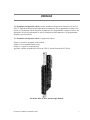
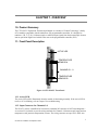
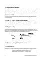
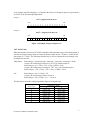
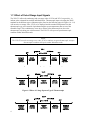
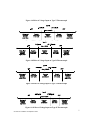
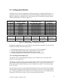
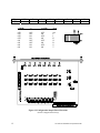
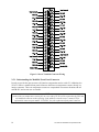
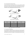
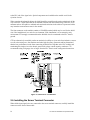
CTI 2559-TC
EIGHT POINT THERMOCOUPLE MODULE
INSTALLATION AND OPERATION GUIDE
Version 1.1
CTI Part #
062-00336-011
*062-00336-010*
2559TCIOG
$25
Copyright © 2005 Control Technology Inc.
All rights reserved.
This manual is published by Control Technology Inc., 5734 Middlebrook Pike, Knoxville, TN
37921. This manual contains references to brand and product names which are tradenames,
trademarks, and/or registered trademarks of Control Technology Inc. and Siemens AG. Other
references to brand and product names are tradenames, trademarks, and/or registered trademarks of
their respective holders.
DOCUMENT DISCLAIMER STATEMENT
Every effort has been made to ensure the accuracy of this document; however, errors do occasionally
occur. CTI provides this document on an "as is" basis and assumes no responsibility for direct or
consequential damages resulting from the use of this document. This document is provided without
express or implied warranty of any kind, including but not limited to the warranties of
merchantability or fitness for a particular purpose. This document and the products it references are
subject to change without notice. If you have a comment or discover an error, please call us toll-free
at 1-800-537-8398.
REVISION HISTORY
Version 1.0
Version 1.1
8/14/02
9/23/04
Original Release
Changed manual to reflect changes in scaling operation
CTI 2559-TC Installation and Operation Guide
iii
PREFACE
This Installation and Operation Guide provides installation and operation instructions for the CTI
2559-TC Eight-Point Thermocouple Input Model for SIMATIC® 505 programmable controllers. We
assume you are familiar with the operation of SIMATIC® 505 programmable controllers. Refer to the
appropriate 505 user documentation for specific information on the SIMATIC® 505 programmable
controllers and I/O modules.
This Installation and Operation Guide is organized as follows:
Chapter 1 provides a description of the module.
Chapter 2 covers installation and wiring.
Chapter 3 is a guide to troubleshooting.
Appendix A details compatibility between the 2559-TC and the Siemens® 505-7028-A.
The Model 2559-TC 8-Pt Thermocouple Module
CTI 2559-TC Installation and Operation Guide
v
USAGE CONVENTIONS
NOTE:
Notes alert the user to special features or procedures.
CAUTION:
Cautions alert the user to procedures that could damage equipment.
WARNING:
Warnings alert the user to procedures that could damage equipment and endanger the user.
CTI 2559-TC Installation and Operation Guide
vii
TABLE OF CONTENTS
PREFACE...........................................................................................................................................................V
USAGE CONVENTIONS ..............................................................................................................................VII
TABLE OF CONTENTS................................................................................................................................. IX
TABLE OF FIGURES..................................................................................................................................... XI
CHAPTER 1. OVERVIEW ...............................................................................................................................1
1.0. Product Summary ......................................................................................................................................1
1.1. Front Panel Description .............................................................................................................................1
1.2. Asynchronous Operation ...........................................................................................................................2
1.3. Immediate I/O............................................................................................................................................2
1.4. J, K, T, E, R, S, N, and mV Thermocouples..............................................................................................2
1.5. Digital Word Map......................................................................................................................................2
1.6. Thermocouple Input to Digital Conversion...............................................................................................2
1.7. Effect of Out-of-Range Input Signals........................................................................................................4
1.8. Additional Error Codes..............................................................................................................................6
1.9. Resolution..................................................................................................................................................6
CHAPTER 2. INSTALLATION .......................................................................................................................9
2.1. Planning the Installation ............................................................................................................................9
2.2. Unpacking the Module ............................................................................................................................10
2.3. Configuring the Module ..........................................................................................................................11
2.4. Inserting the Module into the I/O Base....................................................................................................13
2.5. Wiring the Input Connectors ...................................................................................................................13
2.6. Installing the Screw Terminal Connector ................................................................................................16
2.7. Calibration of the Module........................................................................................................................17
2.8. Checking Module Operation ...................................................................................................................17
CHAPTER 3. TROUBLESHOOTING...........................................................................................................19
HARDWARE SPECIFICATIONS .................................................................................................................21
APPENDIX A. COMPATIBILITY WITH SIEMENS® 505-7028-A.........................................................23
APPENDIX B. JUMPER SETTINGS LOG SHEET.....................................................................................25
APPENDIX C. THERMOCOUPLE WIRE GUIDE .....................................................................................27
LIMITED PRODUCT WARRANTY .............................................................................................................29
REPAIR POLICY.............................................................................................................................................31
CTI 2559-TC Installation and Operation Guide
ix
TABLE OF FIGURES
Figure 1.1 CTI 2559-TC Front Panel.................................................................................................... 1
Figure 1.2 Word Input to the PLC from the Module ............................................................................ 2
Figure 1.3 Example Change in Input Level .......................................................................................... 3
Figure 1.4 Effect of Voltage Input on Type J Thermocouple ............................................................... 4
Figure 1.5 Effect of Voltage Input on Type K Thermocouple.............................................................. 4
Figure 1.6 Effect of Voltage Input on Type T Thermocouple .............................................................. 5
Figure 1.7 Effect of Voltage Input on Type E Thermocouple .............................................................. 5
Figure 1.8 Effect of Voltage Input on Type R Thermocouple .............................................................. 5
Figure 1.9 Effect of Voltage Input on Type S Thermocouple .............................................................. 5
Figure 1.10 Effect of Voltage Input on Type N Thermocouple............................................................ 5
Figure 1.11 Effect of Voltage Input on Type mV Input........................................................................ 6
Figure 1.12 Error Codes........................................................................................................................ 6
Figure 1.13 Input Resolution ................................................................................................................ 7
Figure 2.1 Shipping Jumper Configuration Locations ........................................................................ 11
Figure 2.2 Configuration Jumper Board Locations............................................................................. 12
Figure 2.3 Screw Terminal Connector Wiring.................................................................................... 14
Figure 2.4 Thermocouple wiring application...................................................................................... 15
Figure 2.5 Millivolt wiring application............................................................................................... 15
Figure 2.6 Thermocouple type and wire descriptions ......................................................................... 15
Figure 2.7 Shield Wire Termination ................................................................................................... 16
Figure 2.8 Input Connector Assembly ................................................................................................ 17
Figure 2.9 Example I/O Configuration Chart...................................................................................... 18
Figure 3.1 Troubleshooting Matrix ..................................................................................................... 19
CTI 2559-TC Installation and Operation Guide
xi
CHAPTER 1. OVERVIEW
1.0. Product Summary
The CTI 2559-TC Eight-Point Thermocouple Module is a member of Control Technology’s family
of I/O modules compatible with the SIMATIC® 505 programmable controllers. It is designed to
translate a J, K, T, E, R, S, N thermocouple or millivolt input signals from the thermocouple element
into an equivalent digital word which is then sent to the programmable controller (PLC).
1.1. Front Panel Description
ACTIVE LED
TEMPERATURE
SENSOR A
CHANNELS 1 - 8
TEMPERATURE
SENSOR B
Figure 1.1 CTI 2559-TC Front Panel
1.1.1. Active LED
The Active LED will be illuminated when the module is functioning normally. If the Active LED is
not lit, or if it is blinking, refer to Chapter 3 for troubleshooting.
1.1.2. Input Connector for Channels 1-8
The 2559-TC utilizes a modified 505 connector (a standard 505 connector is NOT interchangeable –
see section 2.5 for details) to provide wiring terminals for Channels 1-8 thermocouple inputs and two
temperature (cold junction compensation) sensors. The wiring connector accepts 14-22 AWG wire.
CTI 2559-TC Installation and Operation Guide
1
1.2. Asynchronous Operation
The module operates asynchronously with respect to the PLC (a scan of the PLC and input sampling
of the module do not occur at the same time). Instead, the module will translate all thermocouple
inputs in one module update (9 milliseconds maximum) and store the translated words in buffer
memory. The PLC retrieves the stored words from the module buffer memory at the start of the I/O
scan.
1.3. Immediate I/O
The 2559-TC has been tested and is fully compatible with the immediate input instruction for the
TI545 and 555 PLCs.
1.4. J, K, T, E, R, S, N, and mV Thermocouples
Each of the module’s 8 channels may be configured to receive either J, K, T, E, R, S, N, or mV
thermocouple input signals. Selection of thermocouple type or millivolts is made via internal dip
switch settings and hardware jumpers (see Section 2.3 Configuring the Module).
1.5. Digital Word Map
Thermocouple and/or millivolt signals are translated into a 15-bit plus sign digital word. Since the
PLC requires a 16-bit input word, the 15-bit value from the converter is placed into a 16-bit word for
transmittal to the PLC, the extra bit being used to show the sign of the word.
Figure 1.2 Word Input to the PLC from the Module
1.6. Thermocouple Input to Digital Conversion
1.6.1. Engineering Units
When module SCALING is disabled, data is reported as engineering units to the PLC as follows:
Thermocouple Mode, digital word (WX) = Degrees x 10
Millivolt Mode, digital word (WX) = -10,000 to +10,000
2
CTI 2559-TC Installation and Operation Guide
As an example, the following Figure 1.3 illustrates the effects of a change in input level going from 0
to 102.4oF in the Thermocouple Input Mode.
Example 1:
0.0oF = (Digital Word (WX))/10
MSB
1
2
0
.
0
.
3
4
5
6
7
8
9
10
0
.
0
0
0
0
0
.
.
.
0
.
0
.
.
.
12
13
14
15
LSB
16
0
0
0
0
0
0
32
16
8
4
2
1
11
Example 2:
102.4oF = (Digital Word (WX))/10
MSB
1
2
0
.
0
.
3
4
5
0
.
0
0
.
6
7
8
9
10
1
0
0
.
0
0
.
.
1024
12
13
14
15
LSB
16
0
0
0
0
0
0
32
16
8
4
2
1
11
Figure 1.3 Example Change in Input Level
1.6.2. Scale Units
When data format is selected as SCALING enabled the full temperature range of the thermocouple is
scaled as an unsigned integer from 0 to 32000 for thermocouple units or –32,000 to +32,000 for mV
units (range of +/-55mV). The following formulas may be used to calculate the scaled integer value
for temperature and mV.
Temperature:
Scaled Integer = (measured temp - min temp) / (max temp - min temp) x 32000
example: the scaled integer offset at 0oC for a Type J thermocouple is:
Scaled integer = (0 - (-210)) / (760 - (-210)) x 32000 = 6928
example: the scaled integer overrange at 770oC for a Type J thermocouple is:
Scaled integer = (770 - (-210)) / (760 - (-210)) x 32000 = 32330
mV:
Scaled Integer = mV x (32,000 ÷ 55)
example: the scaled integer offset at 20 mV is:
Scaled Integer = 20 x (32,000 ÷ 55) = ~11636.36
The table below shows the scaling temperature ranges of each probe type.
Probe Type
J
K
T
E
R
S
N
CTI 2559-TC Installation and Operation Guide
Temperature Range
o
C
F
-210 to 760
-346 to 1400
-220 to 1320
-364 to 2408
-230 to 400
-382 to 752
-240 to 700
-400 to 1292
0 to 1768
32 to 3214
0 to 1768
32 to 3214
-200 to 1300
-328 to 2372
o
3
1.7. Effect of Out-of-Range Input Signals
The 2559-TC utilizes the underrange and overrange codes of 32766 and 32765, respectively, to
indicate when a channel has reached individual limits. Thermocouple inputs exceeding the ANSI
standard for the different types of thermocouples (listed on the following pages in Figures 1.4-1.11)
will cause the overrange value, 32765, to be displayed and the maximum temperature for that
thermocouple type to be returned. Open thermocouples report temperatures that are out of the
allowable range. This condition may occur due to failure of the thermocouple or due to the
thermocouple wire being cut or disconnected. The 2559-TC will report an open thermocouple
condition within 200 milliseconds.
NOTE:
The 2559-TC uses the overrange error code, 32765, to indicate an open thermocouple. An open
thermocouple condition will report within 200 milliseconds.
Figure 1.4 Effect of Voltage Input on Type J Thermocouple
Figure 1.5 Effect of Voltage Input on Type K Thermocouple
4
CTI 2559-TC Installation and Operation Guide
Figure 1.6 Effect of Voltage Input on Type T Thermocouple
Figure 1.7 Effect of Voltage Input on Type E Thermocouple
Figure 1.8 Effect of Voltage Input on Type R Thermocouple
Figure 1.9 Effect of Voltage Input on Type S Thermocouple
Figure 1.10 Effect of Voltage Input on Type N Thermocouple
CTI 2559-TC Installation and Operation Guide
5
Figure 1.11 Effect of Voltage Input on Type mV Input
1.8. Additional Error Codes
In addition to input underrange and overrange error codes (see previous section 1.7.), there exists
two other error codes to be aware of, namely the temperature sensor bad and math overflow codes.
The ‘temperature sensor bad’ code is reported to the PLC when either of the two temperature sensors
encapsulated in front panel connector goes bad. This is a rare occurrence, but would yield code
32,761 if it does occur.
The math overflow code of 32,763 occurs when the thermocouple type mV and SCALE modes are
chosen, and the units tries to report a value under –32,000.
The following chart summarizes the 2559-TC error codes:
Error Code
32761
Error
Bad Temperature Sensor(s)
32763
Math Overflow
32765
Channel Overrange
32766
Channel Underrange
Comment; Corrective Action
A temperature sensor (s) in front panel connector
is faulty/defective; call CTI for replacement 2559TC connector, P/N: 2559-FPC.
Low end range of mV/SCALE exceeded; Check
process to determine if input is actually low.
Determine if mV transmitter is defective.
Input level is above normal input range (see
Figures 1.4-1.11 for each thermocouple type);
Check process to determine if input is actually
high or if the transmitter is defective.
Input level is above below input range (see Figures
1.4-1.11 for each thermocouple type); Check
process to determine if input is actually low or if
the transmitter is defective.
Figure 1.12 Error Codes
1.9. Resolution
The module has a resolution of approximately 0.1oC, 0.1oF or exactly .01 millivolts.
The chart below shows the corresponding input resolution per step for each of the input
configuration modes:
6
CTI 2559-TC Installation and Operation Guide
Units
Temp: oC
Temp: oF
Millivolts
Input Resolution / Step
~0.05oC
~0.09oF
0.0017 millivolts
Figure 1.13 Input Resolution
CTI 2559-TC Installation and Operation Guide
7
CHAPTER 2. INSTALLATION
The installation of the Eight-Point Thermocouple Module involves the following steps:
1.
2.
3.
4.
5.
Planning the installation,
Unpacking and configuring the module,
Inserting the module into the I/O base,
Wiring and connecting the module input connectors,
Checking module operation.
The steps listed above are explained in detail in the following pages.
2.1. Planning the Installation
Planning is the first step in the installation of the module. This involves calculating the I/O base
power budget and routing the input signal wiring to minimize noise. The following sections discuss
these important considerations.
2.1.1. Calculating the I/O Base Power Budget
The Model 2559-TC requires 1.0 watt (maximum) of power from the I/O base. Use this value to
verify that the base power supply is not exceeded.
2.1.2. Input Signal Wiring
Input signal wiring must be shielded twisted pair cable. A twisted pair will aid in the rejection of
conducted and radiated interference from other energy sources. Standard practices usually require
that all shields be tied together and grounded at a single point.
Note the following general considerations when wiring the module:
• Always use the shortest possible cables
• Avoid placing low voltage wire parallel to high-energy wire (if the two wires must meet, cross
them at a right angle)
• Avoid bending the wire into sharp angles
• Use wireways for wire routing
• Avoid placing wires on any vibrating surface
CTI 2559-TC Installation and Operation Guide
9
2.2. Unpacking the Module
Open the shipping carton and remove the special anti-static bag which contains the module.
CAUTION:
HANDLING STATIC SENSITIVE DEVICES
The components on the Model 2559-TC module printed circuit card can be damaged by static
electricity discharge. To prevent this damage, the module is shipped in a special anti-static bag.
Static control precautions should be followed when removing the module from the bag, when
opening the module, and when handling the printed circuit card during configuration.
After discharging any static build-up, remove the module from the static bag. Do not discard the
static bag. Always use this bag for protection against static damage when the module is not
inserted into the I/O backplane.
WARNING:
Ensure that the power supply is turned OFF before connecting the wires to the I/O base.
NOTE:
The 505 front panel connector supplied with the 2559-TC is a modified connector with temperature
sensors built in. Do not attempt to use a standard connector, as the thermocouple measurements will
not be recognized and an error code will be reported on all channels.
10
CTI 2559-TC Installation and Operation Guide
2.3. Configuring the Module
The Model 2559-TC must be configured for the thermocouple type, scaling, digital filtering, and
temperature units before wiring the input connectors and inserting the module into the I/O base. As
shipped, all channels are configured for the type J thermocouple, scaling disabled, digital filtering
enabled, and Fahrenheit (oF) units (see Figure 2.1).
CHANNEL
NUMBER
1
2
3
4
5
6
7
8
THERMOCOUPLE
TYPE JUMPER
JP6/4/5
JP14/12/13
JP18/16/17
JP22/20/21
JP26/24/25
JP30/28/29
JP34/32/33
JP38/36/37
JUMPER POSITION
E or J,K,N,mV or R,S,T
JP4 (type J,K,N,mV)
JP12 (type J,K,N,mV)
JP16 (type J,K,N,mV)
JP20 (type J,K,N,mV)
JP24 (type J,K,N,mV)
JP28 (type J,K,N,mV)
JP32 (type J,K,N,mV)
JP26 (type J,K,N,mV)
DIP SWITCH
SETTING
CH 1 = 010 (type J)
CH 2 = 010 (type J)
CH 3 = 010 (type J)
CH 4 = 010 (type J)
CH 5 = 010 (type J)
CH 6 = 010 (type J)
CH 7 = 010 (type J)
CH 8 = 010 (type J)
SCALING
JUMPER
POSITION
DIGITAL
FILTERING
JUMPER
POSITION
TEMP UNITS
JUMPER
JP1
Dis
JP2
En
JP3
JUMPER
POSITION
o
F
Figure 2.1 Shipping Jumper Configuration Locations
Changing the configuration involves the following steps (notations in parenthesis are actual printed
board titles) described in the following sections:
1. Selecting thermocouple type (E or J, K, N, mV or R, S, or T) for each channel
2. Selecting digital filtering (Enable (EN) or Disable (DIS)) for the module
3. .. Selecting scaling (Enable (EN) or Disable (DIS)) for the module
4. Selecting temperature units (Fahrenheit (F) or Celsius (C)) for the module
2.3.1. Selecting Thermocouple Type
This selection involves both changing the jumpers on a per channel basis as well as dip switch
selection on a per channel basis.
The jumpers, per channel, can be set on one of three posts available used to determine thermocouple
type. The three posts refer to groupings of thermocouple types: “E”, “J, K, N, mV”, and “R, S, T”.
Choose the post for the thermocouple type used. As shipped, each channel is set for thermocouple
types J, K, N, mV.
Once the hardware jumpers are selected this information needs to be reported to the microcomputer.
The information is reported via DIP switches SW1 and SW2 (see Figure 2.2). Each output channel
uses 3 switches with a BCD code to indicate the state of the hardware jumpers. The following chart
illustrates the BCD which is needed to achieve the desired thermocouple type.
CTI 2559-TC Installation and Operation Guide
11
Type
BCD code
MV
000
3 (MSB)
OFF
OFF
OFF
OFF
ON
ON
ON
ON
E
001
2
OFF
OFF
ON
ON
OFF
OFF
ON
ON
J
010
K
011
N
100
1 (LSB)
Type
OFF
ON
OFF
ON
OFF
ON
OFF
ON
mV
E
J
K
N
R
S
T
R
101
S
110
Figure 2.2 Configuration Jumper Board Locations
(shown as shipped from factory)
12
CTI 2559-TC Installation and Operation Guide
T
111
2.3.2. Selecting Digital Filtering
Locate the Digital Filtering Jumper “DIG FILTER” JP2 (see Figure 2.2). To enable digital filtering,
set the jumper in the “EN” position; to disable, set to the “DIS” position. Since many analog input
signals contain noise, CTI recommends using digital filtering unless maximum response time is
required. As shipped, digital filtering is enabled for all 8 thermocouple inputs.
2.3.3. Selecting Offset Scaling
Locate the Offset Scaling “SCALING” jumper JP1 (see Figure 2.2). To enable offset scaling for all
eight inputs set the jumper to the “EN” position. The module will provide the formatted data range as
0-32000 for thermocouples and -32,000 to +32,000 for mV. To disable scaling (and use Engineering
units), set the jumper to the “DIS” position. The module will then format the data range as oC x10 or
o
F x10 for thermocouples and mV from –10,000 to +10,000. As shipped, the jumper is in the DIS
(disable) position.
2.3.4. Selecting Temperature Units
Locate the Temperature Units “TEMP UNITS” jumper JP3 (see Figure 2.2). To enable Fahrenheit
units, set the jumper to the “F” position; to enable Celsius units, set the jumper to the “C” position.
As shipped, the jumper is in the “F” (Fahrenheit) position.
2.3.5. Jumper Settings for Future Reference
See Appendix B. Jumper Settings Log Sheet to record any changes to the module’s jumper settings.
2.4. Inserting the Module into the I/O Base
Insert the module into the I/O base by carefully pushing the module into the slot. When the module
is fully seated in the slot and backplane connector, tighten the captive screws at the top and bottom
to hold the module in place. To remove the module from the I/O base, loosen the captive screws then
remove the module from the I/O base. Be careful not to damage the edge card at the back of the
module when inserting or removing the module.
2.5. Wiring the Input Connectors
Input signals are accepted through a connector assembly located on the front of the module. The
connector assembly consists of a modified Siemens® front panel edge connector with built-in
temperature sensors that mates with the printed circuit board. Wiring is connected to the front
connector via recessed screw terminals. The screw terminals can accept wire sizes up to single
stranded 14-gauge wire. The actual size used depends on the thermocouple wire providing the input
signal.
To assign an input to a specific channel, locate the appropriate channel position on the screw
terminal connector as shown in the following figure:
CTI 2559-TC Installation and Operation Guide
13
Figure 2.3 Screw Terminal Connector Wiring
2.5.1. Understanding the Modified Front Panel Connector
In order to provide the most accurate cold junction compensation and to avoid CJC calibration, the
2559-TC utilizes a modified front panel connector which has two temperature sensors directly set
into the connector. These two temperature sensors are encapsulated in connector locations AR-AC
and DR-DC, and are not user serviceable.
NOTE:
If either of the two temperature sensors fail, an error code of 32,761 will be reported to the PLC and
the modified connector needs replacing. In the unlikely event this occurs, contact CTI for
replacement connector part number ‘2559-FPC’ for your replacement front panel connector.
14
CTI 2559-TC Installation and Operation Guide
2.5.2. Connecting Thermocouple Input Wiring
For thermocouple input circuits, connect the thermocouple wires to the screw terminals, as indicated
in Figure 2.3 Screw Terminal Connector Wiring. Insert the wires in the appropriate holes on the front
of the connector (see Figure 2.4 and 2.5). When the wires are inserted, tighten the screws. Repeat
this procedure for the remaining thermocouple input channels. Ensure that the proper wire polarity is
followed for each of the seven supported thermocouple probe types, as shown in Figure 2.6. See
also Appendix C for more detailed information on different thermocouple types.
Figure 2.4 Thermocouple wiring application
Figure 2.5 Millivolt wiring application
Thermocouple
Type
J
K
T
E
R
S
N
Negative (-)
Lead
Copper-Nickel (Red)
Nickel-Aluminum (Red)
Copper-Nickel (Red)
Copper-Nickel (Red)
Platinum (Red)
Platinum (Red)
Nisil (Red)
Positive (+)
Lead
Iron (White)
Nickel-Chromium (Yellow)
Copper (Blue)
Nickel-Chromium (Purple)
Platinum-13% Rhodium (Black)
Platinum-10% Rhodium (Black)
Nicrosil (Orange)
Figure 2.6 Thermocouple type and wire descriptions
2.5.3. Connecting the Shield Wiring
Control Technology Inc. recommends that all wires be shielded twisted pair with a foil wrap shield
and a separate drain wire and that they be installed in a metallic conduit. For millivolt applications,
use Belden cable 8761 or equivalent which contains a foil wrap shield and a separate drain wire. The
shield and the foil wrap should be twisted together and should be terminated at only one end. The
other end should be left in an open circuit condition. CTI recommends that the shield be terminated
CTI 2559-TC Installation and Operation Guide
15
at the PLC end of the signal wire. Special components are installed on the module to aid in the
rejection of noise.
When entering the industrial cabinet the shield should be routed from the main terminal strip all the
way to the PLC. Signal leads that do not maintain a shield from the terminal strip to the PLC act as
antennas and are susceptible to radiated and conducted emissions in the cabinet. Unprotected cables
may introduce measurement errors in the module.
The front connector on the module contains a CHASSIS terminal which may be used for the shield
wire if the installation is in a noise free environment. If the installation is in an extremely noisy
environment CTI strongly recommends that the shielded wires be terminated to the PLC chassis
ground.
CTI has exhaustively tested this product to maximize its ability to reject noise from inductive sources
as well as showering arcs, fast transients and other high frequency generators and has determined
that the best performance results from connecting all shield wires together at the PLC module and
terminating this single wire to the chassis ground with a large current capacity conductor. CTI
recommends using a #8 gauge wire or larger from the PLC chassis to the earth ground connection.
Figure 2.7 Shield Wire Termination
2.6. Installing the Screw Terminal Connector
When all the input signal wires are connected to the screw terminal connector, carefully install the
connector on the front of the module.
16
CTI 2559-TC Installation and Operation Guide
Figure 2.8 Input Connector Assembly
2.7. Calibration of the Module
Unlike its Siemens® counterpart, the CTI 2559-TC needs no calibration of inputs or cold junction
compensation.
NOTE:
The 2559-TC Thermocouple Input Module is calibrated at the factory. No further calibration is
required. All calibration parameters are stored in non-volatile memory. There are no user
adjustments on this product. As shipped there is no jumper required on the CAL input.
2.8. Checking Module Operation
First turn on the base power. If the module diagnostics detect no problems, the status indicator on the
front of the module will light. If the status indicator does not light, begins blinking (or goes out
during operation), the module has detected a failure. For information on viewing failed module
status, refer to your TISOFT user manual. To diagnose and correct a module failure, refer to the next
section on troubleshooting.
You must also check that the module is configured in the memory of the PLC. This is important
because the module will appear to be functioning regardless of whether it is communicating with the
PLC. To view the PLC memory configuration chart listing all slots on the base and the inputs or
outputs associated with each slot, refer to your TISOFT Programming Manual. An example chart is
shown in the following figure.
I/O Module Definition for Channel…….1 Base..…..00
Number of Bit and Word I/O
I/O Address
Slot
1
2
0001
0000
X
00
00
CTI 2559-TC Installation and Operation Guide
Y
00
00
WX
08
00
WY
00
00
Special
Function
NO
NO
17
.
.
15
16
.
.
0000
0000
.
.
00
00
.
.
00
00
.
.
00
00
.
.
00
00
.
.
NO
NO
Figure 2.9 Example I/O Configuration Chart
In this example, the 2559-TC module is inserted in slot 1 in I/O base 0. Data for channel 1 appears in
word location WX1, data for channel 2 appears in word location WX2, etc. For your particular
module, look in the chart for the number corresponding to the slot occupied by the module. If word
memory locations appear on this line, then the module is registered in the PLC memory and the
module is ready for operation.
If the line is blank or erroneous, re-check the module to ensure that it is firmly seated in the slots.
Generate the PLC memory configuration chart again. If the line is still incorrect, contact your local
distributor or CTI at 1-800-537-8398 for further assistance.
NOTE:
Refer to Hewlett-Packard Applications Note 290 or Omega Temperature Handbook, Volume 26,
Section T, for “practical thermocouple measurement” applications.
CAUTION:
For proper operation, ensure that the 2559-TC and the thermocouple wires are not subjected to
drafts or large temperature gradients during operation.
NOTE:
In the event the 2559-TC detects an onboard module failure, the module will assert the module fail
line and report the module failure in the I/O Status Word, which is reported to the PLC CPU. CTI
strongly recommends the user application monitor the I/O Module Status Words which are Status
Words 11-26 and apply to Controllers TI/545, TI/555, TI/560 & 565, and the TI/575. The I/O
Module Status Word can be used to report a module failure for an I/O Module in any of the 505 I/O
slots. Please refer to Siemens® SIMATIC® TI505 Programming Reference Manual for more
information. If a module failure is reported by the status word, the module should be replaced with a
working unit and the failed module sent in for repair.
NOTE:
It may take 15-30 minutes after initial installation for temperature readings to stabilize.
18
CTI 2559-TC Installation and Operation Guide
CHAPTER 3. TROUBLESHOOTING
If the module provides improper readings or the status indicator is not on, use the following chart to
determine the appropriate corrective action.
Symptom
Indicator is not lit.
Probable Cause
Base or PLC power is off.
Corrective Action
Turn base or PLC on.
Indicator is blinking.
No calibration data.
Return to CTI for calibration.
Incorrect inputs.
Wrong addresses for word input.
Check program for correct work
input addresses.
Not logged in.
Read I/O configuration.
Incorrectly calibrated.
Return the module to CTI for
calibration. DO NOT ATTEMPT
TO CALIBRATE.
Blown fuse.
Measure F1 for continuity. Short
all inputs and verify ambient
temperature measurement.
Input does not work with PID loop
or analog alarm block.
Value is not reported as integer
0-32,000.
Select SCALE format with jumper
JP1 by placing in “EN” position.
Value is too large.
Temperature is reported to PLC as
value x10.
Divide value by 10 in PLC.
Incorrect values to PLC.
(values off by 10-15 degrees)
DIP switch not set in correct
position.
Verify position of DIP switch.
Wrong thermocouple type selected
by jumpers.
Verify position(s) of jumpers.
Temperature sensor(s) damaged.
Order special front panel
connector from CTI, P/N ‘2559FPC’.
(see section 2.5.1.)
Figure 3.1 Troubleshooting Matrix
CAUTION:
The module fuse F1 is not user serviceable. If this fuse is blown, the module has a serious
component failure and should be returned to CTI for repair.
CTI 2559-TC Installation and Operation Guide
19
When it is inconvenient to visually check the status indicator, use the TISOFT “Display Failed I/O”
or “Show PLC Diagnostics” support functions. If after consulting the chart above, you are unable to
diagnose the problem, contact your local distributor or CTI at 1-800-537-8398 for further assistance.
20
CTI 2559-TC Installation and Operation Guide
HARDWARE SPECIFICATIONS
Input Channels:
Thermocouple Types:
Isolation:
Input Overrange Protection:
Measurement Ranges:
Millivolt Input Impedance:
Data Presentation:
Measurement Units:
Digital Filtering Time Constant:
Update Time:
Repeatability:
Accuracy:
ADC Resolution:
Common Mode Rejection:
Normal Mode Rejection:
Connector:
Wire Gauge:
Backplane Power:
Module size:
Operating Temperature:
Storage Temperature:
Relative Humidity:
Agency Approvals Pending:
Shipping Weight:
8 thermocouple inputs
J, K, T, E, R, S, N, and mV
1500V channel-to-backplane
30 VDC or VAC continuous, 120VAC for 10 sec
J: -210oC to 760oC (-350oF to 1400oF)
K: -270oC to 1372oC (-450oF to 2500oF)
T: -270oC to 400oC (-454oF to 752oF)
E: -270oC to 1000oC (-454oF to 1832oF)
R: 0oC to 1768oC (32oF to 3214oF)
S: 0oC to 1768oC (32oF to 3214oF)
N: -260 oC to 1300 oC (-436oF to 2372oF)
mV: -55 to +55mV
4.4MΩ DC, >10KΩ @60 Hz
Scaling Enabled: 0 to 32,000 (temperature)
-32,000 to +32,000 (mV)
Scaling Disabled: oC x10 or oF x10 (temperature)
-10,000 to +10,000 (mV)
o
C or oF (selectable by module)
80 mSec
9 mSec all channels
+/- 1oC, +/-2oF for all thermocouple types
J +/- 1oC at 25oC ambient
K +/- 1oC at 25oC ambient
T +/- 1oC at 25oC ambient
E +/- 1oC at 25oC ambient
R +/- 2oC at 25oC ambient*
S +/- 2oC at 25oC ambient*
N +/- 1oC at 25oC ambient
mV +/- 0.5% full scale or +/- 500µV
*reduced accuracy for measurements below 500oC
16 bits
>110 dB @ 60 Hz
>60 dB @ 60 Hz, >50 dB @ 50 Hz
Removable
14-22 AWG
1.0 Watt (maximum)
Single-wide
0o to 60 oC (32o to 140o F)
-40o to 85o C (-40o to 185o F)
5% to 95% non-condensing
UL, ULC, Class 1-Div.2, CE
1.5 lbs. (0.68 Kg)
- specifications subject to change without notice -
CTI 2559-TC Installation and Operation Guide
21
22
CTI 2559-TC Installation and Operation Guide
APPENDIX A. COMPATIBILITY WITH SIEMENS® 505-7028-A
Overview
The CTI 2559-TC Thermocouple Module was designed to be a drop-in replacement for the
Siemens® Model 505-7028-A. From set up of the module to wiring and PLC reporting, the user will
find many similarities between the CTI and Siemens® models.
Using the CTI 2559-TC in a 505-7028-A application
The CTI 2559-TC should fulfill all the following requirements for the 505-7028-A replacement, as
outlined below:
Module setup
The CTI 2559-TC sets up the same as its Siemen’s counterpart, without any input or CJC calibration
needed. See Chapter 2.3 Configuring the Module for Operation to determine the details in module
setup.
Wiring
The wiring of the input connector is the same between the modules, although the 2559-TC utilizes a
modified 505 front panel connector. See Section 2.5. for details on the modified connector and a
detailed explanation of how proper wiring is accomplished.
PLC Reporting
The word format is the same between the modules. See Chapter 1 for a more detailed explanation on
PLC reporting.
CTI 2559-TC Installation and Operation Guide
23
APPENDIX B. JUMPER SETTINGS LOG SHEET
CHANNEL
NUMBER
1
2
3
4
5
6
7
8
SCALING
THERMO
TYPE JUMPER
JP6/4/5
JP14/12/13
JP18/16/17
JP22/20/21
JP26/24/25
JP30/28/29
JP34/32/33
JP38/36/37
JUMPER
POSITION
JUMPER POSITION
E or J,K,N,mV or R,S,T
DIGITAL
FILTERING
JP1
JP2
JUMPER
POSITION
DIP SWITCH
SETTING
TEMP UNITS
JUMPER
JUMPER
POSITION
JP3
Record the configuration jumper settings on this log for future reference. Make additional copies if
necessary.
NOTE:
The 2559-TC Thermocouple Input Module is calibrated at the factory. No further calibration is
required. All calibration parameters are stored in non-volatile memory. There are no user
adjustments on this product. As shipped there is no jumper required on the CAL input.
CTI 2559-TC Installation and Operation Guide
25
APPENDIX C. THERMOCOUPLE WIRE GUIDE
Chart used with permission from Omega Engineering, Inc.
CTI 2559-TC Installation and Operation Guide
27
LIMITED PRODUCT WARRANTY
CTI warrants that this CTI Industrial Product shall be free from defects in material and workmanship
for a period of one (1) year after purchase from CTI or from an authorized CTI Industrial Distributor.
This CTI Industrial Product will be newly manufactured from new and/or serviceable used parts
which are equal to new in the Product.
Should this CTI Industrial Product fail to be free from defects in material and workmanship at any
time during this (1) year warranty period, CTI will repair or replace (at its option) parts or Products
found to be defective and shipped prepaid by the customer to a designated CTI service location along
with proof of purchase date and associated serial number. Repair parts and replacement Product
furnished under this warranty will be on an exchange basis and will be either reconditioned or new.
All exchanged parts or Products become the property of CTI. Should any Product or part returned to
CTI hereunder be found by CTI to be without defect, CTI will return such Product or part to the
customer.
This warranty does not include repair of damage to a part or Product resulting from: failure to
provide a suitable environment as specified in applicable Product specifications, or damage caused
by an accident, disaster, acts of God, neglect, abuse, misuse, transportation, alterations, attachments,
accessories, supplies, non-CTI parts, non-CTI repairs or activities, or to any damage whose
proximate cause was utilities or utility like services, or faulty installation or maintenance done by
someone other than CTI.
Control Technology Inc. reserves the right to make changes to the Product in order to improve
reliability, function, or design in the pursuit of providing the best possible Product. CTI assumes no
responsibility for indirect or consequential damages resulting from the use or application of this
equipment.
THE WARRANTY SET FORTH ABOVE IN THIS ARTICLE IS THE ONLY WARRANTY CTI
GRANTS AND IT IS IN LIEU OF ANY OTHER IMPLIED OR EXPRESSED GUARANTY OR
WARRANTY ON CTI PRODUCTS, INCLUDING WITHOUT LIMITATION, ANY WARRANTY
OF MERCHANTABILITY OR OF FITNESS FOR A PARTICULAR PURPOSE AND IS IN LIEU
OF ALL OBLIGATIONS OR LIABILITY OF CTI FOR DAMAGES IN CONNECTION WITH
LOSS, DELIVERY, USE OR PERFORMANCE OF CTI PRODUCTS OR INTERRUPTION OF
BUSINESS, LOSS OF USE, REVENUE OR PROFIT. IN NO EVENT WILL CTI BE LIABLE
FOR SPECIAL, INCIDENTAL, OR CONSEQUENTIAL DAMAGES.
SOME STATES DO NOT ALLOW THE EXCLUSION OR LIMITATION OF INCIDENTAL OR
CONSEQUENTIAL DAMAGES FOR CONSUMER PRODUCTS, SO THE ABOVE
LIMITATIONS OR EXCLUSIONS MAY NOT APPLY TO YOU.
THIS WARRANTY GIVES YOU SPECIFIC LEGAL RIGHTS, AND YOU MAY ALSO HAVE
OTHER RIGHTS WHICH MAY VARY FROM STATE TO STATE.
CTI 2559-TC Installation and Operation Guide
29
REPAIR POLICY
In the event that the Product should fail during or after the warranty period, a Return Material
Authorization (RMA) number can be requested orally or in writing from CTI main offices. Whether
this equipment is in or out of warranty, a Purchase Order number provided to CTI when requesting
the RMA number will aid in expediting the repair process. The RMA number that is issued and your
Purchase Order number should be referenced on the returning equipment's shipping documentation.
Additionally, if the product is under warranty, proof of purchase date and serial number must
accompany the returned equipment. The current repair and/or exchange rates can be obtained by
contacting CTI's main office at 1-800-537-8398.
When returning any module to CTI, follow proper static control precautions. Keep the module away
from polyethylene products, polystyrene products and all other static producing materials. Packing
the module in its original conductive bag is the preferred way to control static problems during
shipment. Failure to observe static control precautions may void the warranty. For additional
information on static control precautions, contact CTI's office at 1-800-537-8398.
CTI 2559-TC Installation and Operation Guide
31