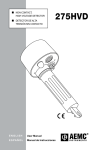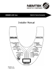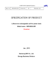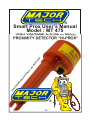
1
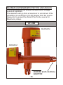
®
Smart Prox User’s Manual
Model : MT 475
Un
ite
d
St
ate
s
De
si
gn
Pa
te
n
t:
US
D4
74
,7
0
5S
HIGH VOLTAGE A.C.(50 or 60Hz)
PROXIMITY DETECTOR ”HI-PROX”
®
-1-
TABLE OF CONTENTS
Description
Safety Rules............................................................
General Description.................................................
Principle of how it work............................................
A quick review of it’s inside working.........................
Low Voltage Testing................................................
Front Panel Layout..................................................
Preparation for use..................................................
Typical uses............................................................
Broken wires in cables............................................
High Voltage Testing...............................................
Non contact advise.................................................
Limitations of the SmartProx MT475.......................
Replacing the batteries............................................
Laboratory and field test results.............................
Specifications..........................................................
Questions and Answers...........................................
Troubleshooting.......................................................
Maximum and minimum detection and angles........
Limited Warranty.....................................................
-2-
Page
03
04
04
05-07
08
08-09
09
10
10
10
10
11
11
12
13
14-16
17
18
19
SAFETY RULES
The Smart Prox Mt475 has been designed with safety in
mind. However, no design can completely protect against
incorrect use.
Electrical circuits are dangerous and lethal through lack
of caution or poor safety practice. Follows Safety rules
to reduce danger and practice safety.
• Read the User’s manual carefully and completely before
using the tester. Fully understand the instructions before
using this product. Follow the instructions for every test.
Take all the necessary precautions. Do not exceed the
limits of this instrument.
• The MT475 should never be in physical contact with any
conductor higher than 1kV, unless utilized with an insulating
Stick. This is a proximity detector, not a detector which work
by contact. As such, contact should be avoided.
• Always use a fiber glass rod or an authorised insulated
stick.
• A High voltage test is carried out with the tester attached to
an operating stick, sometime called “links stick” (Sunrise).
• Double check the Rotary Switch setting before measuring.
Make sure it is on the correct setting for your application.
• Always check that the Mt475 is working Correctly before
and after the test (Standby signals Pulses OK).
• Do not touch any exposed wiring, connections or other
“live” parts of an electrical circuit.
• This instrument should only be used by a competent,
suitably trained person which understand fully this test
procedure. Personal working with High Voltage should
be trained regularly. Use Protective gear.
Caution, risk of electric shock.
Caution, refer to the user’s manual.
-3-
GENERAL DESCRIPTION
The Smart-Prox MT475 consist of an internal pickup AC
sensor plate, a sensitivity rotary selector switch, a test and
diagnostic circuit, a microprocessor, a sound annunciator
(high pitch, high power buzzer), a visual indicator (super high
bright leds) and three “D” size 1.5V batteries, all enclosed
into a water tight & robust nylon case. The end of the battery
holder has the built-in Sunrise (hot stick) adaptor.
PRINCIPLES OF HOW IT WORK
The Smart-Prox MT475 detects AC voltages using it’s AC
sensor plate.
The AC sensor plate pick up part of the radiated electric field
in volts per meter (V/M).
The electric field is processed by the internal circuitry and
triggers the input of a CMOS integrated circuit. This CMOS
Trigger input is then converted to a clean digital signal of the
same frequency of the detected AC signal, which, in turn, is
feed to the microprocessor.
The microprocessor analyze that digital signal and process it
using a D.S.P. Technique.
If the detected signal is between 40 to 70Hz, then, and only
then, the “AC detected” alert is enabled. Once the “AC
detected” Alert is enabled, the buzzer sound and the super
brights leds lit permanently, until the detected signal stops or
until the MT475 get far away from the source.
The “Self-test” diagnostic and test pulses are inserted onto
the sensor plate, just like if the sensor would pick up an AC
voltage. Every part of this instrument are self tested
continuously, while in standby or while waiting for AC.
The Smart-Prox MT475 allows identification of A.C. Voltages
from 240Vac to 275kVac.
The enclosure is made out of a nylon Flame retardant
material.
The enclosure can be attached to a link stick (Sunrise or hot
stick/link stick adaptor built-in).
-4-
A QUICK OVERVIEW OF IT’S INSIDE WORKING
After turning the SmartProx ON (by turning the selector to a
position other than OFF).
1- Wait one or 2 seconds.
The tester must work as normal, that mean that when
the tester is in the “STANDBY” Mode, it BEEP shortly, then,
just after the end of the beep, it FLASH shortly too. It does
that about every 2 seconds when everything is normal.
If this is not happening, then maybe there is a voltage
detection (for example if the BUZZER BUZZ and the LIGHT
LIT continuously, then in this case, rotate the selector to a
higher voltage.
So, if you are not picking any AC (no ac detected), then
the tester should do the following:
-It BEEP shortly, then, just after the end of the beep, it
FLASH shortly too. It does that about every 2 seconds.
-That mean that the Hardware and Software are OK.
-This is what the Smart-Prox does when everything is
normal and when it is in STANDBY mode (waiting to
Detect AC)
2- At OFF POSITION = Turn the rotary selector on
OFF.
The microprocessor detects the “OFF” position
because the test pulses are not coming back to the
microprocessor. So, as when there is something wrong, the
Smart-Prox does nothing. Same thing if there is a hardware
fault or wiring fault.
3- DIAGNOSTIC AND TEST PULSES
At all times, on one of the output pin of the micro, there
are diagnostic and test pulses which are going to the AC
sensor plate, then, these diagnostic and test pulses are read
back by the microprocessor via the plate and back to an
input pin of the microprocessor’s (read back the pulses if
wiring and circuitry correct).
-5-
4- Low Battery Voltage Detector
A 2.5V reference voltage source is present on the PCB.
The Analog to Digital Converter is 10 bits (1024 binary).
The battery low is defined in the software by a value of
650.The battery voltage is read at half the battery voltage
(voltage divided by resistors)
So, Voltage threshold for low battery equal (2.5V/1024)
* 650 = 1.5891V x 2 (because of the voltage divider from the
battery) so the threshold for the low battery indication is
3.17V.
The low battery indication will come at less than 3.17V
±5%.
When Low battery is detected, the buzzer buzz like if it
was morse code. The LEDS are kept OFF to save battery in
this case.
The Low battery only work if the test pulses are OK too.
If there is a AC voltage detected, the Low Battery alert
is disabled (see priority).
5- The Frequency Counter.
Low Limit <37Hz
High Limit >71Hz
The signal input is picked up on the sensor plate, then
directed to the micro. On the micro input pin, there is a
frequency counter, and the software will detect signals
between 37Hz to 71Hz in a Digital Signal Processing
fashion.
All other signals are filtered out by software.
6- Sensitivity.
When the battery goes down, the sensitivity increase.
This is because the threshold level of the first stage of the
shaping circuit goes down too and require less volts to
trigger.
-6-
7- Watchdog Timer.
The microprocessor has a watchdog timer built-in.
Should the program not run as it should, the microprocessor
will reset itself and restart. This is a better way to have a failsafe instrument.
8- Priority of functions - display and sound alertsA= Faulty Hardware or OFF Position
= First Priority
= nothing happen everything OFF
B-
= Voltage Detected
= Second Priority
= Buzzer and Light ON permanently
C-
= Battery Indication
= Third Priority
= Buzzer buzz morse code style
D-
= All OK Signal , tests and diagnostics passed.
= Fourth Priority
= Quick Buzz followed by quick flash light
The Smart-Prox uses a priority system to show the
alerts. When everything is ok, the signal is displayed and
buzz very shortly. If there is a low battery, the buzzer will
beep like a morse code etc... As per the table above. The
voltage indication has always priority on other alerts.
9- Battery Polarity Protection.
A pcb mounted Fuse will blow up if the protection diode
conducts. That diode will only conduct if the batteries are
connected reverse. Please be careful not to connect the
batteries reversed. Check polarity before inserting them.
-7-
LOW VOLTAGE TESTING
Physical contact with electrical conductors is not necessary
when testing for Live Lines. This tester works by proximity.
It’s sensor sense the radiated field which surrounds live
conductors.
It is recommended not to touch High Voltage wires with the
MT 475 (especially if you don’t use an insulating stick, like
the sunrise or hot stick).
Radiated field strength increase with voltage and decrease
quickly with distance or earth shielding.
The radiated field from a cable of closely bunched
conductors supplied by three phase power tend to cancel
(See limitations of use).
Detecting distance of a 240Vac single Live Wire is about
10Cm and with a bunched neutral and earth, as in a flexible
cable, the distance is reduced to 5Cm.
High Pitch Loud Buzzer
S
St un
A ick ris
da ) e
(L
pt
in
or
k
FRONT PANEL LAYOUT
Super High
Bright Leds
Rotary Selector
Battery Holder
-8-
FRONT PANEL LAYOUT
OFF
- Turn the Pick-up sensor “OFF”
240Vac
- 240Vac Selection.
2kV
- 2kVac Selection.
3.3kV
- 3.3kVac Selection.
- 6kVac Selection.
6kV
11kV
- 11kVac Selection.
22kV
- 22kVac Selection.
33kV
- 33kVac Selection.
66kV
- 66kVac Selection.
132kV
- 132kVac Selection.
275kV
- 275kVac Selection.
Buzzer
- High Noise Level Buzzer.
Leds
- Super High Bright Low Current Leds.
Battery Holder.
Sunrise (Hot/Link stick) adaptor
PREPARATION FOR USE
When unpacked, the tester should be inspected for any
visible signs of damage, and the preliminary checks
described (waiting for the Standby - all ok signal) should be
performed to ensure that it is operating correctly. If there is
any sign of damage, or if the instrument does not operate
correctly, return it to your nearest supplier.
This instrument is powered by the three “D” type batteries.
CHECKING AND PROOFING THE TESTER
Switch the sensitivity to any voltage.
After about 2 seconds, the Smart Prox MT475 should beep
and lit shortly, one after the other, about every 2 seconds.
That test is the self diagnostic test which run while in
standby, and indicates that the tester is operational and all is
OK.
Approaching the dome near a computer screen or a T.V. (Not
Liquid Crystal Display type) Screen should also trigger the
tester while on the 240V selection, provided the system
produce an AC 40 to 70 Hz signal.
-9-
TYPICAL USES
Identify and check AC live cables.
Check and Detect Live High Voltage Cables (using extension
Hot Stick or Sunrise).
Fault finding in flexible cables.
Checking equipment earth.
Neon lightning servicing.
Tracing live wires.
Detecting of residual or induced voltages.
(For High frequency radiation checks, use 275HP.)
BROKEN WIRES IN CABLES
Faults in damaged flexible cables are found by applying low
voltage to each conductor in turn, earthing the remainder and
moving the tester along the cable until the change in
condition is obtained (flexible cables as used in mining and
building industries are readily repairable when the break in
the cable is located).
HIGH VOLTAGE TESTING
The rotary selector switch (attenuator) is used to identify and
differentiate various H.V. Live cables.
The tester must be used in conjunction with an long and
insulating rod connected to the Sunrise adaptor ( link
stick adaptor) when measuring High Voltage (kV).
Select the nearest voltage you suspect the cable is supplied
with, then raise the SmartProx near the cable.
If you don’t know which voltage to expect, start with a lower
voltage, then raise the SmartProx until it detect the AC.
You can slowly increase the voltage on the SmartProx (one
step at a time) and raise it again, until you are satisfied. The
detection should happen approximatively 20 to 10Cm from a
live cable to be able to discriminate properly.
-10-
NON CONTACT ADVISE
It is advised that the tester should not come into contact with
cables (kV) as this tester is merely an Non-Contact A.C.
Proximity Tester. !!!!! Distance from source has a large
effect on detection !!!!! (See Page 12 distance Vs MVD)
This advise is particularly useful to protect users which do
not respect protection and safety rules and who do not wear
protective gear.
Also, H.V. Cables are very heavy and powerful. While they
swing, their force could mechanically damage the raised
equipment, or even kick the equipment so hard that the user
could fall onto the ground. Never work alone.
LIMITATIONS ON THE Smart-Prox MT475
It is recommended that this tester is not used in H.V.
Yards of mixed voltages. In the presence of mixed
voltages, the tester can become unreliable.
Problems can arose when the tertiary circuit of a
275/133/11kV transformer is tested. The electric field of
the H.V. And M.V. Bus bars can trigger the detector when
it is about 3m above the ground (this is common with
most of the electric field voltage detectors and the users
should be aware of it).
The tester could pick up adjacent circuit to the one being
tested and indicates the wrong information to the user.
This is why it’s necessary to adjust the sensitivity and
the distance to find the best configuration for your
testing.
REPLACING THE BATTERIES
The Smart-Prox uses 3 x “D” cells batteries. Remove the
battery cover (turn anti-clockwyse) to remove the batteries.
Ensure polarity is respected. Should polarity be reversed, an
internal fuse will be blown by the internal diode protection,
and the MT475 will need to be serviced at an approved
service center.
-11-
LABORATORY AND FIELD TEST RESULTS
Expected Test Results (laboratory testing)
Range
Distance from From Source and M.D.V.
240V
5Cm >30V ;10Cm>270V
2kV
5Cm >1kV ;10Cm>2kV
3.3kV
5Cm >2kV ;10Cm>3kV
6kV
5Cm >2.5kV ;10Cm>4kV
11kV
5Cm >5kV ;10Cm>8kV
22kV
5Cm >7kV ;10Cm>12kV
33kV
5Cm >9kV ;10Cm>13kV
66kV
5Cm >21kV ;10Cm>39kV
132kV
5Cm >37kV ;10Cm>not tested in our I-H lab.
275kV
not tested in our I-H lab.
See next page about specifications at 1Cm
Typical Observation of test Results made in the field.
Range Min. Detection Voltage MDV as % of Line Voltage
11kV
1kV
9.1%
22kV
2kV
9.1%
33kV
3.1kV
9.4%
132kV
12.5kV
9.5%
275kV
22.5kV
8.2%
These typical observation are from when nearly touching the
cable or touching the cable. Tests performed on a 50Hz
network.
Problems can arose when the tertiary circuit of a
275/133/11kV transformer is tested. The electric field of
the H.V. And M.V. Busbars canTrigger the detector when
it is about 3m above the ground (this is common with
most of the electric field voltage detectors and the users
should be aware of it).
The tester could pick up adjacent circuit to the one being
tested and indicates the wrong information to the user.
-12-
SPECIFICATIONS
ELECTRICAL
Detecting Ranges (Vac 40 to 70 Hz)
Selection Detects voltage from 1Cm distance.
240V
80V
2kV
500V
3.3kV
640V
6kV
1kV
11kV
1.8kV
22kV
2.8kV
33kV
3.3kV
66kV
8.9kV
132kV
12.6kV
275kV
not tested in our in-house lab
MECHANICAL
Case Height
Case Width
Case Depth
Bump Test
Vibration Test
Drop Test
Impact Test
Weight
:
:
:
:
:
:
:
:
:
ENVIRONMENTAL
Operating Temperature:
Storage Temperature:
Humidity:
Cold Temperature:
Dry Heat:
Damp Heat:
260mm
97.5mm
97.5mm
IEC68-2-29
IEC1010, clause 8.3
IEC1010, clause 8.4
IEC1010, Clause 8.2
502.3g with batteries
303.2g without batteries
-15ºC to + 55ºC
-20ºC to + 65ºC
93% RH @ 40ºC
IEC68-2-1
IEC68-2-2
IEC68-2-3
-13-
Questions / Answers
Leds / Buzzer Driven independently I assume that the
buzzer and LEDs are controlled separately by the micro?
Why is this better?
There are 2 transistors driven independently from 2 different
pins of the micro. If one circuit should fail, it is unlikely that the
other would fail at the same time. So, the user could still use the
tester to detect Vac as when Vac is detected, both the buzzer
and the Red Light must be ON. If one failed, the user would
know that when the Light or the Buzzer is ON, it’s that Vac has
been detected. This is the only case where the buzzer or the
light stays ON. They are both independent from each other,
even inside the micro, the pins are separates.
D.S.P. Type Pass Band Filter 40 to 70 Hz Is this to limit the
detected voltages to “line” systems only?
Yes, the MT 475 must only detect 50 or 60Hz basically, this is
because the HiProx would also buzz with static electricity, for
example when you rub it on your clothes. Of course, It does not
matter if it does that when you rub it on your clothes, that was
the old accepted method of testing if the product was working in
the past. But when the head of the HiProx is close to a dead HV
cable which is swigging in the air, that static also trigger the
HiProx, not the MT475.
In some cases, the MT475 kept buzzing on dead cables, just
because of the static generated by the swing on the cable in
the air. The use of a digital filter make the other products look a
bit “old” by it’s ability to differentiate between non AC signal and
signals which are not between 40 to 70 Hz
-14-
Does this improve voltage discrimination where there are
dual voltages (we have LV cables at 1 level on the pole and
then 11kV a few meters higher on the same pole and some
times the 11kV signal can confuse someone testing the LV
(415V) lines.
I would think that it does not, where mixed voltages are present,
the same thing should happen.
The way to discriminate that is with the sensitivity selector and
the distance.
Different Alerting Sounds and Light What are the different
sounds and lights and what do they do?
If the tester is in the off position, then it look dead, everything
is off, the light and the buzzer and can't detect anything -It’s
OFF-.
If the tester is on (any sensitivity) and the batteries are ok and
no Vac is detected, it does buzz quickly and then flash quickly
too, then send the Test and Diagnostic pulses, analyze them
and if the batteries are ok and no Vac is detected, it does buzz
quickly and then flash quickly too, then send the Test and
Diagnostic pulses ...etc...
If batteries are too low, it does pulse the buzzer only (morse
code type) then still ,send the Test and Diagnostic pulses,
analyze them, etc....
In the case of low batteries, the MT475 does only buzz the
buzzer morse code type to conserve battery life. All the other
functions are still actives. As the batteries goes down, the
sensitivity increase automatically.
If Vac 40 to 70Hz is detected, it does buzz and light
continuously.
The Vac detection Alert has priority on the low battery and on
the all ok signals. So even if everything is ok and if the battery is
low, if it detects Vac, it will go into voltage detection mode and
pass the low battery alert and the everything ok alert.
-15-
The Low battery has priority on the all ok signals. Even if
everything is ok, if a low battery is detected, the MT 475 will
buzz pulse morse sound type, but still measure Vac, etc...
Fail Safe Design by Watch Dog Timer What does this do?
If for any reason the software get stopped or if there is a
condition which stops the micro, it will reset by itself and restart,
just like an ON/OFF switch. The watch dog timer keep
everything running smoothly, if the software does not goes
where it should, then it will reset the device and start from
scratch again.
Standby ‘All OK’ Quick Buzz then Quick Lit When I turn the
sample ON it just goes straight into the test diagnostic
pulse mode. Is it supposed to do a “full Check” first with
the LEDs and Buzzer coming ON together for a second or
so?
The tester start working normally after around one to 2
seconds. it will goes straight in test diagnostic pulse mode after
starting. It does a full check all the time, unless Vac is detected.
Priority Alert System: Vac, Low Bat, OK What is this
doing?
same as different alerting sounds and light explanation above.
-16-
TROUBLESHOOTING
I turn the MT475 ON (selector not OFF) and I don’t get
any “ALL OK signals” (no quick buzz, followed by no
quick red flash).
If you don’t have the “Standby” all OK signals, replace the
batteries, they might be so low that the tester don’t even
start. The microprocessor will not start if the voltage has not
at least 2.6V
THE SMART PROX HAS A “BATTERY - REVERSE INSERTION PROTECTION FUSE”. VERIFY THAT THE FUSE HAS NOT BEEN BLOWN.
THE FUSE IS SITUATED INSIDE THE TESTER ITSELF. SHOULD
REPLACEMENT OF BATTERY NOT SOLVE THE PROBLEM, It’S MOST
LIKELY THAT THE FUSE HAS BEEN BLOWN. CHECK WITH YOUR
NEAREST SERVICE CENTER.
I turn the MT475 ON (selector not OFF) and only a quick
buzz occurs (not followed by quick Red Flash light).
The transistor driving the Super High Bright Leds could be
broken, send for service.
I turn the MT475 ON (selector not OFF) and only a quick
red flash occurs (no quick buzz).
The transistor driving the buzzer could be broken, send for
service.
-17-
MAXIMUM AND MINIMUM DETECTION AND ANGLES
The angle between the SmartProx and the AC voltage
source is important.
The detection will go from a maximum to a minimum if the
SmartProx is turned from 0 to 90 Degree from the source.
Always try to present the Smart Prox to the source for
Maximum pickup.
AC LINE
MAXIMUM
MINIMUM
SUNRISE (Hot/Link Stick)
ADAPTOR
-18-
LIMITED WARRANTY
We warrant the product manufactured by us to be free from
defective material or factory workmanship and agree to repair
or replace this product which, under normal use and service,
disclose the defect to be the fault of our manufacturing, with
no charge for parts and service. If we are unable to repair or
replace this product, we will make a full refund of the
purchase price.
Consult the user’s manual for proper instruction regarding
use of this instrument.
Our obligation under this warranty is limited to repairing,
replacing or making refund of this test equipment which
proves to be defective within forty eight months from the date
of original purchase.
This warranty does not apply to any of our products which
have been repaired or altered by unauthorized persons in any
way so as, in our sole judgement, to injure their stability or
reliability, or which have been subject to misuse, abuse,
misapplication, negligence or accident or which have had the
serial numbers altered, defaced or removed.
Accessories, not of our manufacture used with this product,
are not covered by this warranty.
All warranties implied by law are hereby limited to a period of
forty eight months, and the provisions of the warranty are
expressly in lieu of any other warranties expressed or
implied.
The purchaser agrees to assume all liability for any damages
or bodily injury which may result from the use or misuse of
the product by the purchaser, or it’s user, his employees, or
others, and the remedies provided for in this warranty are
expressly in lieu of any other liability we may have including
incidental or consequential damages.
We reserve the right to discontinue models at any time, or
change specification, price or design, without notice and
without incurring any obligation.
-19-