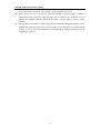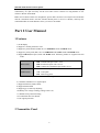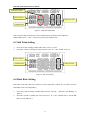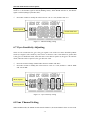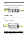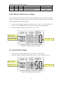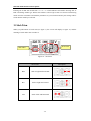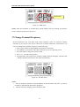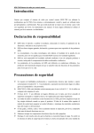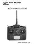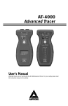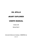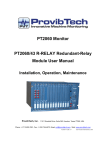
1
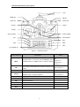
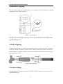
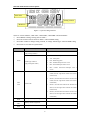
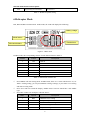
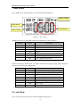
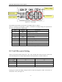
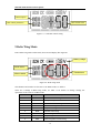
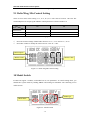
KDS-7XII Radio Remote Control System Introduction Thank you for purchasing KDS-7XII Radio Remote Control System (hereafter called K-7XII). This system is extremely versatile and may be used by beginners and professionals alike. In order for you to make the best use of your system and to fly safely, please read this manual carefully. If you have any difficulties while using your system, please contact your hobby dealer. Liability Declaration KDS model has the right to change the product, including the exterior, the functions parameter, and use request, but no notice. KDS model does not provide any guarantee, declaration and promise for special use of any KDS products. The recommended or text technologies data in the technology introduction for KDS model only indicates the test result at that time, but it does not mean KDS model acknowledges the result in law. KDS model will not be responsible for the result made by using any product or circuit, including the incidental or indirect compensation. The parameters of KDS electronic products will be changed under different conditions. The products will work only after all the functions parameters are approved by each use intension. Precaution of Safety It requires professional skills and technical knowledge to install and operate R/C model properly. Incorrect installation and operation will result in severe property loss and personal injuries. KDS-7XII 2.4GHz is exclusively designed for civil use of R/C models. Don’t use it in any other flying machines. The governmence for R/C model is different in different place, therefore, please consult your local regulatory body and follow the rules and regulations to operate legally. Radio wave transfers almost in straight routine in 2.4GHz, please make sure there is no any obstacle when you are operating the product. The antenna tube should point at the controlled model to ensure efficient control, and keep conductive materials away from receiver and transmitter. If there is prang, collision, welter and other accidents when operating, please test all the things before next operating. Always keep electronic components away from small children. Stop flying long before your batteries become low on charge. Do not rely on your radio's low battery warning systems, intended only as a precaution, to tell you when to recharge. Always check your transmitter and receiver batteries prior to each flight. While you are getting ready to fly, if you place your transmitter on the ground, be sure that -1- KDS-7XII Radio Remote Control System the wind won’t tip it over. If it is knocked over, the throttle stick may be accidentally moved, causing the engine to speed up. Also, damage to your transmitter may occur. Before taxiing, be sure to extend the transmitter antenna to its full length. A collapsed antenna will reduce your flying range and cause loss of control. It is a good idea to avoid pointing the transmitter antenna directly at the model, since the signal is weakest in that direction. Don’t fly in the rain! Water or moisture may enter the transmitter through the antenna or stick openings and cause erratic operation or loss of control. If you must fly in wet weather during a contest, be sure to cover your transmitter with a plastic bag or waterproof barrier. Never fly if lightning is expected. -2- KDS-7XII Radio Remote Control System Part 1 Quick Start KDS-7XII is advanced electronic device, and features wide use. It can support multi-users and multi-equipment simultaneously, and features quick response, high precision, and strong capability for anti-jamming. KDS-7XII supports one transmitter and several receivers, and makes it possible that single radio can control several models. KDS-7XII supports different brand gyros. KDS-7XII reacts quickly and precisely. 1. Mounting of Receiver Installation position shall follow these conditions: 1) Keep the receiver away from engine, motor, ESC, battery, and other metal parts. 2) The antenna can not be covered by metal, carbon material or other electronic conduction materials. 3) Keep the antenna in 90 degrees with installed frame or bottom plate, which means that trying to keep the antenna visible. Recommended installation mode for 450 helicopter -3- KDS-7XII Radio Remote Control System 2. Connect Devices to Receiver Connect all devices and parts to the corresponding channels. Take notice of 3P signal wire must be connected in right way. Otherwise, it will cause the severe damage to certain device or fail to work. There are some corresponding symbols of 3P on one side of the receiver: (-) means cathode of power connected to the earth, usually links to the black line or brown line of 3P signal wire (+) means the anode of power, usually links to the red wire of 3P signal wires. (s) means signal wire, usually links to the white or yellow wire of 3P signal wires. Notice: please assess the power demand of the receiver of model when selecting the electricity supply style, ensure the receiver can get enough power supply when using, the voltage of the receiver not less than 4.2V at any time. 3. Binding Transmitter and Receiver Before using K-7XII, you must bind the transmitter and the receiver. Binding them as following steps: 1) Plug the 'BIND line' into the 'BIND' slot of receiver. Then power on receiver by plugging the ESC line, then the LED of receiver will flash fast. Then you can remove the 'BIND line'. 2) Hold 'ESC' button of transmitter, then turn on it (keep holding), the LCD will display as following. 3) After few seconds, binding will finish, the LED of receiver will shine three times slowly, and then the transmitter enters working mode. 4) Release 'ESC' button of transmitter, it will enter working mode. Notice: 1) K-7XII supports multiple receivers operation and long-distance binding, so please make sure only you bind the radio at that time. If there is any person who also uses KDS-7XII 2.4GHz remote controller system locally, please operates only after other users pare the signal. 2) K-7XII supports seven models saving in one transmitter. They are numbering as M/1 to M/7. The binding will save the serial numbers in receiver. So if you bind one receiver with M/1, it can only work when the transmitter is switched to M/1. 4. Control Distance All radio control system equipment has an effective control range. It’s not the same on the ground, water surface or flying in the sky; It is not the same on flat ground or complicated layout; It’s not -4- KDS-7XII Radio Remote Control System the same in rainy days or sunny days; And besides, the external electrical environment is changing continuously. It’s quite necessary for the users who want to control at a long distance to test effective distance beforehand. Radio wave transfers almost in a straight line, please make sure there is no object between antenna and the controlled model. And the antenna should point at receiver’s antenna, and keep the controlled model in certain distance where you can see the model. Part 2 User Manual 1 Features 1) LCD display 2) Support 7 models parameters store 3) Support 5 points throttle (THR) curve in NORMAL mode and IDLE mode. 4) Support 5 points pitch (PIT) curve in NORMAL mode, IDLE mode and HOLD mode. 5) Support HELI (helicopter) mode and AERO mode. Following modes are supported in each mode: HELI mode HP1: Normal helicopter with 1 servo HP2: Swash helicopter with 2 servos HP3: CCPM 120°swash helicopter with 3 servos AERO mode A/P : Normal aero plane V/P : V-tail plane D/P : Delta wing plane Table1 - Model type list 6) 7 channels standard servo signal output 7) Support Dual rate (D/R) control 8) Support throttle hold 9) Support gyro sensitivity adjusting 10) Battery low voltage warning (voltage can be set). 11) Throttle stick position warning 12) Countdown timer for throttle 13) No signal protection 2 Transmitter Panel -5- KDS-7XII Radio Remote Control System ANT GEAR SW DR SW IDLE SW HOLD SW HOOK STICK STICK STICK TRIM STICK TRIM POWER SW UP INC MENU ESC DN DEC LCD DISPLAY Figure 1 - Transmitter panel Switch & Button Description IDLE In HELI mode, it is used to switch NORMAL mode and IDLE mode. In AERO mode, it controls channel 6. See section-6.9 section-6.10 section-7 DR It is used to control dual rate of aileron, elevator and rudder. See section-6.4 HOLD THR hold switch. See section-6.6 GEAR In AERO mode, it controls channel 5. In HELI mode, it controls channel 7. See section-7 See section-6.8 UP MENU Page up button Menu button DN Page down button INC Increase button ESC Escape button DEC Decrease button Table2 - Button list -6- Detail KDS-7XII Radio Remote Control System 3 Batteries Charging If you are using 8 pcs Ni-Cd or Ni-Mh batteries, you can charge it with a external power without getting batteries out, shown as Figure 2. Figure 2 - External Power Warning: The external power should be 12V, the current should be at least 50mA. Other style may be dangerous! 4 Stick Adjusting To adjust the stick length, use 1.5mm inner hexagon screw driver to unlock the set screw. Turn the screw driver counter-clockwise to loosen the screw. Then, turn the stick clockwise to shorten or counter-clockwise to lengthen. After the control stick length have been adjusted to suit your flying style, tighten the set screw. Figure3 - Stick Adjusting 5 System Setting Hold MENU button and turn on transmitter, it will enter system setting mode, and the first item is shown like following: -7- KDS-7XII Radio Remote Control System Item name Setting content Model No. Figure 4 - System setting interface There are 6 items "MOD", "STK TYP", "BAT WAR", "BAT MIN" and "BAT MAX". Press MENU to change setting item as Table 3 Press UP or DN to choose model as Table 3 when in MOD setting Press INC or DEC to change setting contents, or change "Model Type" when in MOD setting. Press ESC to save and exit system mode. Item name Description Content Model selection Support 7 models, see Section-10 (By pressing UP/DN ) MOD Model type selection (By pressing INC/DEC) A/P : Normal aero plane V/P : V-tail plane D/P : Delta wing plane HL1: Normal helicopter with 1 servo HL2: Swash helicopter with 2 servos HL3: CCPM 120°swash helicopter with 3 servos Mode 1 (the left hand controls the throttle and rudder, and the right hand controls the aileron and elevator) Mode 2 (the left hand controls the elevator and rudder, and the right hand controls the aileron STK TYP and throttle) Stick mode Mode 3 (the left hand controls the throttle and aileron, and the right hand controls the rudder and elevator) Mode 4 (the left hand controls the elevator and aileron, and the right hand controls the rudder and throttle) BAT WAR BAT MIN BAT MAX Voltage for battery warning Battery indicator high limit Battery indicator low limit -8- KDS-7XII Radio Remote Control System ID GEN Regenerating ID of transmitter See section 17 Table 3 - Details of system setting 6 Helicopter Mode HP1, HP2 and HP3 are HELI mode. In this mode, the LCD will display like following: Battery voltage Model status Throttle timer Mix control status Figure 5 - HELI mode In HELI mode, the corresponding content of each channel shown in Table 4. Channel Control Description 1 AIL Aileron 2 ELE Elevator 3 THR Throttle 4 RUD Rudder 5 GY Gyro 6 PIT Pitch 7 AUX Auxiliary Table 4 - HELI mode Channels list Press MENU will enter setting mode. In HELI mode, there are 11 items which can be set, see Table 5. During setting, you can press MENU to change settings, or press ESC to exit setting and return to using mode. Press UP or DN can switch the display "Model status" between "Model No." and "Model type" Press INC or DEC can modify the "Throttle Timer" Index Caption Description 1 REV Channel reverse setting 2 EPA End point adjustment 3 TRM Channel sub trim setting 4 D/R Dual rate setting 5 EXP Exponent setting -9- KDS-7XII Radio Remote Control System 6 HLD Throttle hold setting 7 GYO Gyro sensitivity adjustment 8 AUX Aux channel setting 9 THR Throttle curve setting 10 PIT Collective pitch curve setting 11 PLA Swash plate setting Table 5 - HELI mode settings In HELI mode, there are 4 mix control status: Mix control status Description dR1 Rate 1 Rate 1 of dual rate dR2 Rate 2 Rate 2 of dual rate HLD Hold Hold mode IDL Idle Idle mode Table 6 - HELI mode mix control status 6.1 Reverse Setting Press UP or DN to change channel index from "CH1" to "CH7". Press INC or DEC to modify the reverse status. Menu caption NOR: normal REV: reverse Channel index Figure 6 - Reverse setting 6.2 End Point Adjustment Press UP or DN to change channel index from "CH1-/CH1+" to "CH7-/CH7+". Press INC or DEC to modify the value between "0" to "+120", default value is 80. -10- KDS-7XII Radio Remote Control System End point rudder Menu caption End point value Channel index Figure 7 - End point adjustment Note: about K-7XII, the end point value in both directions of channel can be adjusted independently, and “+” and “-” represent respectively both directions 6.3 Sub Trim Setting Press UP or DN to change channel index from "CH1" to "CH7". Press INC or DEC to modify the value between "-100" to "+100", default value is 0. Menu caption Channel index Sub trim value Figure 8 - Sub trim setting 6.4 Dual Rate Setting DR switch control the dual rate of aileron, elevator and rudder. And the rate of aileron, elevator and rudder can be set independency. Press UP or DN to change channel index between "Aileron ", "Elevator" and "Rudder" as Table 6. Press INC or DEC to modify the value between "0" to "+120". Default value is 100 for DR SW=0, 60 for DR SW=1. -11- KDS-7XII Radio Remote Control System Menu caption Channel index Dual rate value Figure 9 - Dual Rate Setting Channel index Description A/1 Aileron rate when DR SW=0 A/2 Aileron rate when DR SW=1 E/1 Elevator rate when DR SW=0 E/2 Elevator rate when DR SW=1 R/1 Rudder rate when DR SW=0 R/2 Rudder rate when DR SW=1 Table7 - Dual rate setting 6.5 Exponent Setting Press UP or DN to change channel index between "Aileron", "Elevator" and "Rudder". Press INC or DEC to modify the value between "-45" to "+45". Default value is 0. Menu caption Channel index Exponent value Figure 10 - Exponent setting 6.6 Throttle Holding Setting Throttle holding will lock the throttle at setting value. In lock status, the throttle signal be not -12- KDS-7XII Radio Remote Control System changed even if the throttle stick is changed. It is controlled by HOLD switch. When HOLD switch to 1, the throttle signal is locked (holding status), when HOLD switch to 0, the throttle signal is normal (change by throttle stick). Press INC or DEC to modify the value between "-20" to "+20", default value is 0. Menu caption Throttle hold value Figure 11 - Throttle holding setting 6.7 Gyro Sensitivity Adjusting There are two sensitivities for gyro. The gyro signal is one of the two values decided by IDLE switch (see Figure1). The sensitivity value can be set between -100~+100. When it is greater than 0, the gyro is in head-lock mode, when the value is less than or equal to 0, the gyro is in non-lock mode; when the value is equal to 0, the gyro does not work. Press UP or DN to change channel index between "NOR" and "IDL". Press INC or DEC to modify the value between "-100" to "+100", default is +100 for NOR and -100 for IDL. Menu caption Switch position Gyro sensitivity Figure 12 - Gyro sensitivity setting 6.8 Aux Channel Setting When in HELI mode, the GEAR switch controls channel 7, the AUX channel. There are two items -13- KDS-7XII Radio Remote Control System in AUX channel setting, SW1 and SW2, control the signal of AUX channel when GEAR switch in different position. Press UP or DN to change channel index between "SW1" and "SW2". Press INC or DEC to modify the value between "-100" to "+100", default value is +100 for SW1 and -100 for SW2. Menu caption Switch position Channel value Figure 13 - Aux channel setting 6.9 Throttle Curve Setting There are two throttle curves in K-7XII, one is for NORMAL mode, and the other is for IDLE mode. Every curve has 5 points. Each point means the relation between signal and stick position as Table 8. Press UP or DN to change channel index between "N/1" to "N/5" and "I/1" to "I/5". "N/?" for NORMAL mode and "I/?" for IDLE mode. Press INC or DEC to modify the value between "0" to "+100". Menu caption Curve point index Curve point value Figure 14 - Throttle curve setting Curve point index Stick position N/1 I/1 H/1 Stick at lowest position N/2 I/2 H/2 Stick at 25% position -14- Default signal value 0 +25 KDS-7XII Radio Remote Control System N/3 I/3 H/3 Stick at center +50 N/4 I/4 H/4 Stick at 75% position +75 N/5 I/5 H/5 Stick at highest position +100 Table 8 - Throttle curve stick value 6.10 Collective Pitch Curve Setting There are three collective pitch curves, the first is for NORMAL mode, the second is for IDLE mode, and the third is for HOLD mode. Every curve has 5 points. Each point means the relation between signal and stick position as Table 8. Press UP or DN to change channel index between "N/1" to "N/5", "I/1" to "I/5" and "H/1" to "H/5". "N/?" for NORMAL mode, "I/?" for IDLE mode and "H/?" for HOLD mode. Press INC or DEC to modify the value between "0" to "+100". Menu caption Curve point index Curve point value Figure 15 - Collective pitch curve setting 6.11 Swash Plate Setting Press UP or DN to change channel index between "AIL", "ELE" and "PIT". Press INC or DEC to modify the value between "-100" to "+100". Default value is +50. Menu caption Swash dimension Mix control value Figure16 - Swash plate Mix control setting -15- KDS-7XII Radio Remote Control System 7 Aero Mode A/P is AERO mode. In AERO mode, the LCD will display like Figure 17: Battery voltage Model status Throttle timer Mixture status Figure 17 - Aero mode In AERO mode, the corresponding content of each channel is shown in Table 9 Channel Control Description 1 AIL Aileron 2 ELE Elevator 3 THR Throttle 4 RUD Rudder 5 GER Gear, control by GEAR switch 6 FLP Flap, control by IDLE switch 7 AUX Aux, control by D/R switch Table 9 – AERO channels list There are 8 settings in AERO mode, see Table10 for details. To change settings, the operations are the same as the operations in HELI mode. Index Caption Description 1 REV Channel reverse setting 2 EPA End point adjustment 3 TRM Channel sub trim setting 4 D/R Dual rate setting 5 EXP Exponent setting 6 HLD Throttle hold setting 7 GER Gear setting 8 FLP Flap setting Table 10 – AERO settings 8 V-tail Mode V/P is V-tail mode. In this mode, the LCD will display like Figure 18: -16- KDS-7XII Radio Remote Control System Battery voltage Model status Throttle timer Mixture status Figure 18 – V-tail mode The channels and switches are the same as in AERO mode, see Table 9. There are 9 settings in V-tail mode, see Table 11 for details. To change settings, the operations are the same as the operations in HELI mode. Index Caption Description 1 REV Channel reverse setting 2 EPA End point adjustment 3 TRM Channel sub trim setting 4 D/R Dual rate setting 5 EXP Exponent setting 6 HLD Throttle hold setting 7 GER Gear setting 8 FLP Flap setting 9 MIX V-tail Mix control setting Table 11 - V-tail settings 8.1 V-tail Mix control Setting There are four items in this setting: E>2, E>4, R>2 and R>4. The value is between -100 to 100. The relationship between output signal and Mix control parameters is shown in Table 12. Signal CH2 CH4 Elevator stick E>2 E>4 Rudder stick R>2 R>4 Description CH2= Elevator x(E>2)+ Rudder x(R>2) CH4= Elevator x(E>4)+ Rudder x(R>4) Stick Table 12 - V-tail signal Pressing UP or DN will change setting from E>2 to R>4. Pressing INC or DEC will increase or decrease the value. See Figure 19. -17- KDS-7XII Radio Remote Control System Menu caption Mix control parameters Mix control value Figure 19 - V-tail Mix control setting 9 Delta Wing Mode D/P is Delta wing mode. In this mode, the LCD will display like Figure20: Battery voltage Model status Throttle timer Mixture status Figure 20 - Delta wing mode The channels and switches are the same as in AERO mode, see Table 9. There are 9 settings in Delta wing mode, see Table 13 for details. To change settings, the operations are the same as in HELI mode. Index Caption Description 1 REV Channel reverse setting 2 EPA End point adjustment 3 TRM Channel sub trim setting 4 D/R Dual rate setting 5 EXP Exponent setting 6 HLD Throttle hold setting 7 GER Gear setting 8 FLP Flap setting 9 MIX Delta wing Mix control setting -18- KDS-7XII Radio Remote Control System Table 13 - Delta wing settings 9.1 Delta Wing Mix Control Setting There are four items in this setting: A>1, A>2, E>1, E>2. The value is between -100~100. The relationship between output signal and Mix control parameters is shown in Table 14. Signal CH1 CH2 Aileron stick A>1 A>2 Elevator stick E>1 E>2 CH1= Aileron x(A>1)+ Elevator x(E>1) CH2= Aileron x(A>2)+ Elevator x(E>2) Stick Description Table 14 - Delta wing signal Mix control Press UP or DN to change channel index between "A>1", "A>2" and "E>1", "E>2". Press INC or DEC to modify the value between "-100" to "+100". Menu caption Mixture index Mixture value Figure 21 - Delta wing Mix control setting 10 Model Switch K-7XII can support 7 models; each model has its own parameters. To switch among them, you should enter system mode by holding MENU and turning on transmitter. The following screen will be shown. Model type Model index Figure 22 - Model switch -19- KDS-7XII Radio Remote Control System Pressing UP or DN will switch from "-1-" to "-7-" which indicate each model. Pressing INC or DEC will change model type. When some model is selected, press ESC to return to normal using mode. Now the transmitter will load the parameters of your selection and all your settings will be saved into the model you selected. 11 Stick Trim When you pull buttons of stick trim (see figure 1), the screen will display as figure 23, and the meaning of stick index refer to Table 15: Trim value Stick index Figure 23 - Stick trim Stick index Description R/H Stick of right and horizontal R/V Stick of right and vertical L/H Stick of left and horizontal -20- KDS-7XII Radio Remote Control System L/V Stick of left and vertical Table 15 - Stick index 12 Throttle Warning K-7XII supports throttle warning. If the stick of throttle is not in the lowest position when the transmitter is on, it will block in warning status. You will see "THRO" in screen and hear continuously beep till you move the stick to the lowest position. Figure 24 - Throttle warning 13 IDLE Warning K-7XII supports IDLE warning. If the IDLE switch on when power on, the transmitter will block in warning status. You will see "IDLE" in panel and hear continuously beep till you switch IDLE to off. Figure 25 - IDLE warning -21- KDS-7XII Radio Remote Control System 14 Countdown Timer for Throttle K-7XII has a countdown timer relate to throttle. When in normal using status, you can see the timer on the center of screen. The default value is five minutes, like Figure 26. You can press INC or DEC to change the value. The max value is 99 minutes. When you push throttle stick up, the timer will run from the value you set to zero. When at the last 1 minute remaining, the transmitter will beep to notify you. Throttle timer Figure 26 - Throttle countdown timer 15 No Control Protection K-7XII supports 'No Control Protection' function. You can predefine a set of values for each channel. The receiver will use these values if it loses signal from transmitter. To set the values, you should do as following steps: 1) Turn on the transmitter and receiver, bind them. 2) Adjust the transmitter, and make all channels to the position as you expect. 3) Hold ESC button until the screen of transmitter will display 'NCP' like Figure 27, and the RF LED shines, and the LED of receiver will go out at the same time. 4) After 1 second, the transmitter and the receiver will restore to normal status, the defining of ' No Control Protection ' is done. Notification Figure 27 - No Control Protection setting 16 Using PPM Signal There is a PPM signal output slot at bottom of K-7XII. When you plug the signal line into the -22- KDS-7XII Radio Remote Control System slot, K-7XII will switch to PPM status automatically and you will see following screen. Notification Figure 28 – PPM status Notice: when the transmitter is in PPM status, the RF module will stop working, and then the receiver will lost signal if it was power on. 17 Change Transmit Frequency Electric interference may exist when using remote controller system. If it interferes with the frequency of your system, your devices will be out of control. Under these circumstances, you can try to change the transmitter frequency by following steps: 1. 2. 3. 4. 5. Enter system mode by holding MENU and turning on transmitter Press MENU several times to "ID GEN" function, you can see following screen Press UP or DN to change the option to 'YES' Press + or - to confirm the operation The transmitter will regenerate the frequency and ID, and then the display will show 'OK' and the transmitter will return to 'NO' status automatically. Figure 29 – ID GEN menu Notice: 1. The new frequency and ID are selected randomly. If the interference still exists, you can try to change it again until the interference disappears. 2. After the frequency changing, please rebind the radio. -23-