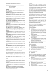
1
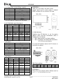
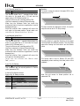
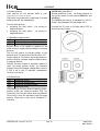
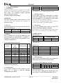
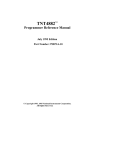
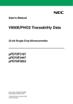
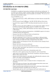
ROTADRIVE User manual RDxx-P8-xx-xx-E1-xx Profibus DP, CANopen, RS232/RS485 Description This manual describes the ROTADRIVE series with Profibus DP, CANopen and RS232/RS485 interfaces. ROTADRIVE is a complete positioning unit which integrates a DC gear-motor, a drive, an encoder and a controller. Failure to comply with these precautions or with specific warnings elsewhere in this manual violates safety standards of design, manufacture, and intended use of the instrument. Lika assumes no liability for the customer's failure to comply with these requirements. Co nne c ta c c o r d i ng t ot he c ha p t e r3 :“ E l e c t r i c a l c o nne c t i o n” . 1.1 Safety button A safety button for emergency switch-off has to be installed to interrupt motor power supply. 2 - Identification The device can be identified by the label's data (ordering code, serial number). This information is listed in the delivery document. For technical features of the product to make reference at the technical catalogue. Chapters 1 2 3 4 5 6 7 8 9 10 Safety summary Identification Installation & electrical connections Parameter Functions Profibus DP interface CANopen interface RS232/RS485 interface Diagnostics Controller set up 1 - Safety summary We strongly recommend carefully reading this user manual and following the installation guidelines below: High current, voltage, and rotating parts can cause serious or fatal injury. The use of electric machinery, like all other uses of concentrated power and rotating equipment, may be hazardous. Installing, operating, and maintaining electric machinery should be performed by qualified personnel only. 3 - Installation & electrical connections 3.1 Mounting instructions Rotadrive can be mounted directly on a spindle with Ø14mm and fixed by means of the collar and the anti-rotation pin. The unit can be mounted in any position. In order to guarantee the maximum life of mechanical parts of the RD11, we recommend to use a flexible coupling between Rotadrive and spindle. 3.2 Electrical connections ATTENTION ! The transmission of a Start command moves the unit and the axis. Make sure no personal injury and mechanical damage can be caused. Each Start routine has to be taken out with care! Layout electrical connections according to local norms and laws. Avoid running the signal cables near high voltage power cables (e.g. motor power supply, drive cables). Always use shielded and twisted cables if possible. _____________________________________________________________________________________ MAN RDxx-P8-xx-xx-E1-xx E 1.0 Pag. 1 www.lika.it www.lika.biz ROTADRIVE 3.2.1 CON1 DSub 5+2 pin (Power supply) Pin Function A1 +24Vdc (motor) A2 GND 1 Output (5Vdc - active LOW) * 2 +24Vdc ±10% (controller) 3 Input 3 4 Input 2 5 Input 1 *: on RD12 and RD22 output is not connected. 3.2.2 CON2 DSub 9 pin (Interfaces) Pin Profibus DP CANopen RD1 RD2 RD1/RD2 1 n.c. n.c. n.c. 2 n.c. n.c. CAN-Low 3 B (Profi.) B (Profi.) n.c. 4 B (RS485) RD(RS232) B (RS485) 5 GND GND GND 6 +5Vdc n.c. +5Vdc 7 n.c. n.c. CAN-High 8 A (Profi.) A (Profi.) n.c. 9 A (RS485) TD(RS232) A (RS485) 3.2.3 Cable 1 Colour Brown (1mm2) White Grey Brown (0.25mm2) Green Red Blue RS485 RD1/RD2 n.c. n.c. B (RS485) B (RS485) GND +5Vdc n.c. A (RS485) A (RS485) Function +24Vdc (motor) GND Output (5Vdc - active LOW) * +24Vdc (controller) Input 3 Input 2 Input 1 3.2.4 Cable 2 Color Profibus DP RD1 RD2 Blue n.c. n.c. Brown n.c. n.c. Pink B (Profi.) B (Profi.) B RxD Violet (RS485) (RS232) Black GND GND Red +5Vdc n.c. Grey A (Profi.) A (Profi.) A TxD Green (RS485) (RS232) CANopen RS485 RD1/RD2 RD1/RD2 CAN-Low n.c. CAN-High n.c. n.c. B (RS485) B (RS485) B (RS485) GND +5Vdc n.c. GND +5Vdc A (RS485) A (RS485) A (RS485) ATTENTION ! CON2, pin 6 and Cable2, color Red (+5Vdc): output signal used for power supply of external RS485 converter. Do not connect if not used. RD2 / RD3 RD1 3.3 Dip-Switches Rotadrive has DIP-Switches to set the device address (SW1) and Bus termination (SW2) if Rotadrive is an end device: SW1= binary switch to set device address SW2 = ON if RDx is end device/bus termination OFF if RDx is not end device To access DIP-Switches remove the PG-closure on the back of the device. RD2 / RD3 SW1 Device address: bit 6 5 weight 2^5 2^4 RD1 4 2^3 3 2^2 2 2^1 1 2^0 ATTENTION ! Using Drive-tool software device address must be s e tt o“ 1 1 ”f o rRS 2 3 2 / RS 4 8 5i nt e r f a c e . _____________________________________________________________________________________ MAN RDxx-P8-xx-xx-E1-xx E 1.0 Pag. 2 www.lika.it www.lika.biz ROTADRIVE 4 - Parameters ATTENTION ! Some parameters have a profound effect on the operation of the drive. They must not be altered without careful consideration of the impact on the controlled system. Measures must be taken to prevent unwanted changes due to error or tampering. Admissible value range for each parameter is listed as follows: [unit/ min. value, max. value] Default parameter values are written in BOLD characters. All parameters with decimals are transmitted without decimal point: x.x = xx x.xxx = xxxx Parameters with unit P05 are related to the engineering unit set in parameter P05. 4.1 Parameter description P00 Actual position [P05/ ---, ---] Contains the actual position. The measurement unit is related to parameter P05. P00 equals P01 if the unit is positioned within the tolerance window (P09). P01 Target position [P05/ -2147483648, 2147483648] Contains the target position to reach after the start command. Default value: 0 P02 Datum value (Preset) [P05/ -2147483648, 2147483648] Contains the datum (or preset) value. The actual p o s i t i o nwi l lb es e tt ot hi sv a l uea f t e ra“ Go -toDa t um“o r“ S e t -Da t um”c o mma nd . Offset value (P33) will be added if set. Default value: 0 P03 Software limit [P05/ -2147483648, 2147483648] Lowest target value to be accepted in P01. Default value: -100000 P04 Software limit + [P05/ -2147483648, 2147483648] Highest target value to be accepted in P01. Default value: 100000 P05 Distance for scaling factor [any measuring unit/ 1, 100.00] Position value after 1 turn of the shaft. Enter value without decimals. Default value: 2.00 Example 1: The spindle has a pitch of 2 mm. You want to display a resolution of 0,01 mm. P05 would be 200 (2.00 without decimal point) P08 Nr. of automatic restarts [nr./ 0, 255] The unit restarts automatically if after positioning, the (new) actual position (P00) is not within Target position (P01) ± tolerance window (P09). Default value: 0 P09 Tolerance window [P05/ 0, 255] Tolerance window around the target position. The controller as a proper target position accepts any position inside this window. Default value: 0 P10 “ I n-P o s i t i o n”t i me[x.xx sec/ 0.00, 2.00] Sets the time for which a holding current is provided to keep the motor in position after reaching the target position. After this time the driver wont energize the motor in order to avoid over-heating. Over-running of target position due to short standstill time and big inertia could be caused if P10 is too small. Default value: 0.10 P11 Acceleration ramp [P05/ 255, 16000] Sets the length of positive and negative acceleration ramp expressed in increments (e.g. 2000 = +1000 / 1000). High values mean low acceleration (longer ramp). Too low values could cause unacceptable current peaks. Default value: 2000 _____________________________________________________________________________________ MAN RDxx-P8-xx-xx-E1-xx E 1.0 Pag. 3 www.lika.it www.lika.biz ROTADRIVE P21 Differential gain [increments/ 0, 10000] Sets the differential gain that is active only in the deceleration ramp. This parameter is useful if the motor stops before) reaching the target position (or slows down too early). The differential gain gives the motor a short acceleration before target position by means of a ramp increment. 0 = D-gain disable … 10000 = D-gain generates 10000 Ramp increments. P13 Fast speed [%/ 1, 100] 1%...100%: Percentage of max. fast speed in manual and automatic positioning mode. Default value: 100 P14 Manual slow speed [%/ 1, 100] 1%...100%: Percentage of max. slow speed in manual positioning mode. Default value: 100 P15 Stop-ramp (activated by Stop command) [xxxx msec/ 1, 2000] Sets the time to decelerate and stop the motor in after a STOP command. Default value: 100 P16 Step length in manual mode [P05/ 0, 10000] Sets the length in increments of each Step for the Step+ and Step- commands. Default value: 1 P17 Backlash compensation dwell time [x.xx sec/ 0, 20.00] Sets the dwell time before starting the backlash compensation. If set to 0 the parameter is disabled. Default value: 0.00 P18 Backlash compensation distance [P05/ 0, 250] Sets the backlash compensation distance. The unit will overrun the target position for this distance before backlash compensation. Default value: 0 P26 Counting direction [---/ 0, 1] Sets the counting direction of the controller. 0 = standard direction 1 = inverted direction P26=0 and P42=0 is standard (cw counting and rotation from shaft side). It is necessary to change both P26 and P42 to invert the counting direction. P27 Go-To-Datum direction [---/ 0, 1] 0 = in (+) direction 1 = in (-) direction P28 Home position after Go-To-Datum routine [P05/ -2147483648, 2147483648] Sets the home position to go to after Go-To-datum routine. Default value: 0 P29 Reference switch for Go-To-Datum routine [---/ 0, 1] 0 = Reference switch active low 1 = Reference switch active high P33 Go-To-Datum offset [P05 / -2147483648, 2147483648] Sets the offset value to assign after Go-To-Datum routine. Go-To-Datum routine is completed when _____________________________________________________________________________________ MAN RDxx-P8-xx-xx-E1-xx E 1.0 Pag. 4 www.lika.it www.lika.biz ROTADRIVE reaching the first index pulse after leaving the reference switch. New actual position P00 = Reference value P02 + Offset P33 Default value: 0 P36 Closed loop control [---/ 0, 1] Enables the closed loop control. 0 = disabled (OFF) 1 = enabled (ON) P08 should be set to 0 P37 Closed loop response time [Nr. of cycles/ 1, 250] Sets the response time (expressed in 0.5 ms cycles) of closed loop function at any change of the target position. Suggested value is 2 Default value: 1 (0.5 ms) P38 Closed loop tolerance window [P05/ 0, 50000] Sets a tolerance window expressed in increments. After positioning the actual value should be target value ± tolerance window. If not the closed loop control will be enabled and move the axes to correct position. Inside the tolerance window the closed loop control is not enabled. Default value: 1 (means ±1 increments) P39 Closed loop mode [---/ 0, 1] Sets the closed loop operating mode. 0 = only active after each positioning (active on target value). 1 = also active after pressing Stop button or when switching power on. P42 Motor rotation direction [---/ 0, 1] Sets the motor rotation direction. 0 = standard 1 = inverted P26=0 and P42=0 is standard (cw counting and rotation from shaft side). It is necessary to change both P26 and P42 to invert the counting direction. Default value: 2000 P45 Go-To-Datum speed [%/ 1, 100] Sets the Go-To-Datum speed expressed percentage of max. speed. Default value: 50 in P46 Function input 1 [---/ 0, 4] (option) Sets the function of digital Input 1. 0 = Start * 1 = Stop * 2 = Reference switch * 3 = no function 4 = BCD coded input (only for Drive-Tool) P47 Function input 2 [---/ 0, 4] (option) Sets the function of digital input 2. 0 = Start * 1 = Stop * 2 = limit switch negative direction * 3 = no function 4 = BCD coded input (only for Drive-Tool) P48 Function input 3 [---/ 0, 4] (option) Sets the function of digital input 3. 0 = Start * 1 = Stop * 2 = limit switch positive direction * 3 = no function 4 = BCD coded input (only for Drive-Tool) * Start function is active high (rising edge) * Stop function is active low (falling edge) * Limit switch functions are active low. When input is high, movement is possible, when input is low movement is blocked. P49 Function output [---/ 0, 3] Sets the function of digital output 1. 0 = in position 1 = brake active 2 = device moving 3 = no function P43 Deceleration ramp [P05/ 255, 16000] Sets the length of deceleration ramp expressed in P50 Brake active time [sec./ 0, 1000] increments. Only for RD11 and RD22. Great values stand for long deceleration ramps. Low Determines how long the brake has to be active. values (short deceleration distance) may cause Default value: 0 overrunning. _____________________________________________________________________________________ MAN RDxx-P8-xx-xx-E1-xx E 1.0 Pag. 5 www.lika.it www.lika.biz ROTADRIVE 4.2 Read-only parameter P52 Command word [---/ 128, 139] Shows the command in use. P80 Controller status [---/ 0, 255] Shows controller status. Hex Dec Description 00 0 axis not ready 01 1 axis ready 02 2 axis is moving 04 4 axis in target position 08 8 searching zero position 10 16 over current 20 32 shortcut 40 64 system error 80 128 target position value out of range Power supply error. Power off F0 240 time too short for parameter storage operation. P81 Reference switch/Encoder index distance [P05/ 0, 255] Shows the distance between reference switch and encoder zero index. P82 Actual motor current [x.xx Ampere/ 0.00, 10.00] Shows the motor current. P83 Actual ramp value [Ramp increments/ 0, 255] Shows the actual ramp value of PWM controller. P84 Controller correction value [Ramp increments/ 0, 32000] Shows the actual correction value of the controller. P85 Go-To-Datum status [Status/ 0, 3] Shows the status of Go-To-Datum routine. 0 = Go-To-datum routine initialized 1 = Axis reached reference switch 3 = Axis reached reference switch and then encoder index. 4.3 List of Rotadrive parameters Please write down the values of all parameters on this list for assistance and service. Nr. Parameter Value P00 Actual position P01 Target position P02 Datum value P03 Software limit P04 Software limit + P05 Distance for scaling factor P08 Nr. of automatic restarts P09 Tolerance window P10 “ i np o s i t i o n”t i me P11 Acceleration ramp P13 Fast speed P14 Manual slow speed P15 Stop-ramp (Stop command) P16 Step length in manual mode P17 Backlash compensation dwell time P18 Backlash compensation distance P21 Differential gain P26 Counting direction P27 Go-To-Datum direction P28 Home position after Go-To-Datum routine P29 Reference switch for Go-To-Datum routine P33 Go-To-Datum offset P36 Closed loop control P37 Closed loop response time P38 Closed loop tolerance window P39 Closed loop mode P42 Motor rotation direction P43 Deceleration ramp P45 Go-To-Datum speed P46 Function Input 1 P47 Function Input 2 P48 Function Input 3 P49 Function output P50 Brake active time P52 Command word P80 Controller status P81 Reference-Index distance P82 Actual motor current P83 Actual ramp value P84 Controller correction value P85 Go-To-Datum status _____________________________________________________________________________________ MAN RDxx-P8-xx-xx-E1-xx E 1.0 Pag. 6 www.lika.it www.lika.biz ROTADRIVE 4.4 List of Info parameters Nr. Parameter P00 Identification (nr. of axes) P01 Identification (Device address) P02 Identification (Version) P03 Identification (Customer) P10 Profibus address P11 Profibus status P25 Nr. power downs P26 Max. current of axis P29 Working time P30 Nr. of power on/off P31 Nr. start routines P34 Nr. of Go-To-Datum routines P37 Nr. of over current errors P40 Nr. of limit switch errors P43 Nr. of shortcuts P46 Nr. feedback errors 4.5 Factorypa r a me t e r s( don’ tc ha nge ) Value NOTE: List of Info parameters is not available with Profibus interface, to access it use Serial or CANopen interface. Parameters P10 and P11 are referred only to Profibus interface Nr. P06 P07 P19 P20 P22 P23 P24 P25 P30 P31 P32 P34 P35 P40 P41 P44 P51 P55 Default value Encoder resolution [Pulses/1,65000] 2000 Max. permanent current 2.50 [x.xx Ampere/ 0.01, 10.00] Integral gain 1 [Nr. of cycles/1, 999] 10 Integral gain 2 [Nr. of cycles/1, 999] 10 Feedback monitoring interval 10 [Nr.of cycles: x.x*0.5 ms/0,1000] Feedback-control on acceleration 1 ramp [Pulses/ 1, 255] Feedback-control on deceleration 1 ramp [Pulses/ 1, 255] Edge counting mode [Edges/ 0, 4] 4 Index pulse edge trigger [---/ 0, 1] 1 Standstill-control sampling time 0.100 [x.xxx sec/ 0.000, 32.000] Max. peak current 3.50 [x.xx Ampere/ 0.01, 10.00] Over current time interval [x..xx 0.10 sec/ 0.01, 4.00] Ramp threshold to activate encoder 50 -monitoring interval [%/0,100] Max. feedback counting frequency 0 [Hz/ 1, 300000] Feedback frequency sampling 0 interval [ms/ 0, 1000] Proportional gain [---/ 0, 8] 8 I-limit 0 Integral gain 3 [---/ 100, 1000] 800 Parameter _____________________________________________________________________________________ MAN RDxx-P8-xx-xx-E1-xx E 1.0 Pag. 7 www.lika.it www.lika.biz ROTADRIVE 5 - Functions 5.1.1 Start routine The Start command moves the positioning unit to the target position accordingly to the ramp parameters set (see also chapter 10 Controller set up). When it has reached the position inside the tolerance window, the controller gives an inposition signal. I t ’ sp o s s i b l et oc ha ng et het a r g e tp o s i t i o na ndt he motor speed while positioning. A new Start command will change the positioning routine to the new values. If the new target position is in opposite (negative) direction the controller will change the motor direction after doing a Stop ramp. Settings of speed will be enabled after “ Activate parameters”command. ATTENTION ! The positioning speed can be changed “ o nt hefly” . T hi sd o e s n’ tc ha ng et hep a r a me t e ra ndd o e s n ’ tne e d “ Activate parameters”command. 5.1.2 Stop routine The Stop command interrupts the positioning routine and stops the motor according to the stop ramp settings. 5.2.1 Manual mode Step + P14 Manual slow speed P16 Step length in manual mode The Manual mode Step + command will move the unit for one Step according to the value of P16 at the speed P14. This command sets: Target position P01 = actual position P00 + P16. Note that another Start command will move the unit again to the same position. 5.2.2 Manual mode Step P14 Manual slow speed P16 Step length in manual mode The Manual mode Step - command will move the unit for one Step according to the value of P16 at the speed P14. This command sets: Target position P01 = actual position P00 - P16. Note that another Start command will move the unit again to the same position. 5.3.1 Manual mode Slow + P14 Manual slow speed P04 Software limit + The “ Manual mode slow +”command slows down the motor to the speed set in P14, sets the target value to P04 (Software limit +). The unit moves until reaching position P04. Use Stop command to interrupt the positioning. Make sure the Software limits are inside the mechanical limits of machine or application to avoid damage and injury. Note that another Start command will move the unit again to the same position. To move to another position a new target value has to be set. 5.3.2 Manual mode Slow P14 Manual slow speed P03 Software limit The “ Manual mode Slow -”command slows down the motor to the speed set in P14 and sets the target value to P03 (Software limit -). The unit will move until reaching position P03. Use Stop command to interrupt the positioning. Make sure the Software limits are inside the mechanical limits of machine or application to avoid damage and injury. Note that another Start command will move the unit again to the same position. To move to another position a new target value must be set. _____________________________________________________________________________________ MAN RDxx-P8-xx-xx-E1-xx E 1.0 Pag. 8 www.lika.it www.lika.biz ROTADRIVE 5.4.1 Manual mode Fast + P13 Fast Speed P04 Software Limit + The “ Manual mode Fast +”command slows down the motor to the speed set in P13 and sets the target value to P04 (Software limit +). The unit will move until reaching position P04. Use Stop command to interrupt the positioning. Make sure the Software limits are inside the mechanical limits of machine or application to avoid damage and injury. Note that another Start command will move the unit again to the same position. Target value now c o i nc i d e swi t h“ Ma nua l mo d eF a s t +”p o s i t i o n. 5.4.2 Manual mode Fast P13 Fast Speed P03 Software limit The “ Manual mode Fast -”command slows down the motor to the speed set in P13 and sets the target value to P03 (Software limit -). The unit will move until reaching position P03. Use Stop command to interrupt the positioning. Make sure the Software limits are inside the mechanical limits of machine or application to avoid damage injury. Note that another Start command will move the unit again to the same position. T a r g e tv a l ueno wc o i nc i d e swi t h“ Ma nua lmo d e Fast-”p o s i t i o n. Routine: The motor moves the axis at the speed P45 in the direction set in P27. The axis actuates the Reference switch, the motor stops the axis as set in P15 (Stop-ramp). The axis restarts in opposite direction at the speed P14 and leaves the Reference switch. The first Index pulse after leaving the limit switch sets the Datum value. The Actual value is set to Datum (P2 and P33) immediately when reaching the Index pulse of the feedback. 5.5.1 Set-To-Datum P02 Datum value This command sets the actual position to Datum value (parameter P02). 5.5.2 Go-To-Datum routine Starts a Go-To-Datum routine. P02 Datum value P45 Go-To-Datum speed P27 Go-To-Datum direction P28 Home position after routine P29 Reference switch for routine Now the unit moves to Home position set in parameter P28. Go-To-Datum Go-To-Datum _____________________________________________________________________________________ MAN RDxx-P8-xx-xx-E1-xx E 1.0 Pag. 9 www.lika.it www.lika.biz ROTADRIVE 5.6 Limit switches Limit switches set the extreme limits of your a p p l i c a t i o n’ sme c ha ni c a l s t r o k e . Limit switch inputs are safe to cable break (if a cable breaks motor will stop immediately). The unit will stop when: activating the Limit switch + by moving in positive direction activating the Limit switch - by moving in negative direction IMPORTANT (only RD1) ! Manual mode slow + and - can be done directly on the unit by means of push-buttons MANUAL+ and MANUAL-. The DATUM push-button is equivalent to "Set-ToDatum" (see parameter P02 and chapter 5.5.1) Unscrew the PG cover on the back-side of RD1 to access the push-buttons. 5.7 Backlash compensation P17 Backlash compensation dwell time P18 Backlash compensation distance P08 Nr. of automatic restarts Backlash errors of the spindle or gearbox can be avoid moving to target positions always in the same direction. The unit will overrun the target position of the distance set in P18 and hold for the time set in P17. Positive values of P18 overrun the target position in positive direction whereas negative values overrun in negative direction. P08 sets the max. number of automatic restarts to reach the target position (within the tolerance window) during the backlash compensation routine. If P08 is set to zero (0) backlash compensation function is not active. 5.8 Closed loop P36 Closed loop control P37 Closed loop response time P38 Closed loop tolerance window P39 Closed loop mode The Closed loop function allows to keep the unit in position (within the tolerance window P38). The closed loop function gets active when any external force tries to move the axis away from the target position. Closed loop is done by an intelligent PIcontroller. _____________________________________________________________________________________ MAN RDxx-P8-xx-xx-E1-xx E 1.0 Pag. 10 www.lika.it www.lika.biz ROTADRIVE 6 - Profibus DP interface 6.1.1 Introduction The following chapters describe the cyclic data transfer. The layout of data transfer has been optimized for drives, to be fast and at constant time intervals. 6.2.1 Parameter request When the master requests a parameter from the unit, PWE contains the assigned parameter value IND contains the axis nr. PNU the parameter nr. 6.1.2 GSD File Ro t a d r i v ei ss up p l i e dwi t hi t ’ sGS Df i l eRDxxx.gsd (see enclosed support or www.lika.biz > products > actuators). The GSD file has to be installed in your Profibus-DP master device. 6.2.2 Parameter change After changing a parameter must be activated by “ activate parameter”c o mma nd( v a l ue3 ) . To store the parameter (into EEProm) it must be s a v e db yt he“ save parameter”c o mma nd( v a l ue4 ) . 6.1.3 Telegram structure Byte Field Function 1 AK* Acknowledgement 2 PNU Parameter nr. 3 IND axis nr. 4 SUBIND reserved 5 6 PWE Value of parameter 7 8 9 I/O 1 Input/Output 1 10 I/O 2 Input/Output 2 11 ZSW/STW Status word / Command word 12 13 14 HIW/HSW Target position / Actual position 15 16 ATTENTION ! If not saved the parameter will be cancelled after power off. T he“ s a v ep a r a me t e r ”r o ut i nel a s t sa p p r o x .5 0 0ms . During this time no Parameter- or Save commands can be send to the device. * structure of AK Bit 7 6 5 SISB AK 6.3.1 Parameter OK The parameter has been accepted. 4 3 SPM 2 1 ERR 0 6.2 AK Acknowledgement Master Slave Bits 0, 1, 3 (ERR), 3 (SPM) and 7 (SISB) are not used and therefore set to 0 (zero). The status of bits 4, 5, 6 (AK) indicates if the data transmission has been performed successfully or not. Example: You send a parameter and Rotadrive replies AK=01(Hex) parameter is ok. 6.2.3 Master Slave functions AK value Description 0 no command 1 request parameter value 2 change parameter value 3 activate parameter 4 save parameter (on EEProm) 6.3 AK Acknowledgement Slave Master The device issues an error message against incorrect parameter requests. 6.3.2 Parameter error Error value Description Parameter nr. not valid 2 (range of parameters is from 0 to 80) Parameter value not valid 3 (see value range of each parameter in parameter list) 6.3.3 Axis error Axis number not valid (see IND). _____________________________________________________________________________________ MAN RDxx-P8-xx-xx-E1-xx E 1.0 Pag. 11 www.lika.it www.lika.biz ROTADRIVE 6.3.4 Slave Master functions AK value Description 0 not valid 1 parameter OK 2 parameter nr. not valid 3 parameter value not valid 4 axis nr. not valid 6.3.5 SISB Not used. 6.3.6 SPM Not used. 6.4 PNU (byte 2) Parameter number (see parameter list) 6.5 IND (byte 3) Rotadrive is a single axis unit. Set IND always 0 (zero). 0 = axis nr. 1 6.6 SUBIND (byte 4) Reserved bits, set always to 0 (zero) 6.7 PWE (byte 5-8) Contains the parameter value. Byte 8 is LSB (least significant byte). At power-on PWE contains the service time of RD. 6.8 I/O 1, Digital input (byte 9) Contains input signal status. 01(Hex) : High Input 1 02(Hex) : High Input 2 04(Hex) : High Input 3 6.9 I/O 2 (byte 10) Not used. 6.10 ZSW/STW (byte 11-12) Only byte 11 is used. Byte 12 is always zero. ZSW shows the status of the unit after a command from the Master. Communications Slave Master hex dec Description 00 0 axis not ready 01 1 axis ready 02 2 axis moving 04 4 axis in position 08 8 Go-To-Datum routing active 10 16 over current 20 32 shortcut 40 64 encoder error/malfunction 80 128 target position out of range F0 240 power supply error The unit can respond with a combination of the above information. Example: 03(Hex) means Rotadrive is ready and moving. 05(Hex) means Rotadrive is within the tolerance window. STW contains the command to send. Following commands are available. Commands Master Slave hex dec Description 80 128 Start axis 81 129 Stop axis 82 130 Manual mode Step + 83 131 Manual mode Step 84 132 Manual mode Slow + 85 133 Manual mode Slow 86 134 Manual mode Fast + 87 135 Manual mode Fast 88 136 Start Go-To-Datum routine 89 137 Activate parameters 8A 138 Save data (EEProm) 8B 139 Go-To-Datum 8C 140 Feedback frequency 6.11 HIW/HSW (byte 13-16) Contains the actual position and target position. _____________________________________________________________________________________ MAN RDxx-P8-xx-xx-E1-xx E 1.0 Pag. 12 www.lika.it www.lika.biz ROTADRIVE 7 - CANopen interface 7.1 Introduction CANo p e np r o f i l ed e f i net he“ Ar b i t r a t i o nf i e l d ”( COBI D)a ndt he8b y t e s“ Da t af i e l d ”( CANd a t ab y t e s )o f CAN frame. The following chapters describe asynchronous data transfer. Rotadrive is always a slave device. COB-ID(hex) 700+Node ID 1 CAN Data Bytes 00 T hee nc o d e ri sno wi n“ pre-o p e r a t i o na l ”s t a t e . IMPORTANT: For every omitted specify make reference to the d o c ume nt“ Ci A Dr a f tS t a nd a r d3 0 1 ”a v a i l a b l eo n www.can-cia.org. PRE-Operational In this state, node can communicate to master throw SDO message. SDOs are used to set or read slave parameters. In pre-operational mode, slave c a n’ ts e ndP DOo rE me r g e nc yme s s a g e s . T op utno d ei n“ Op e r a t i o na l s t a t e ” , ma s t e rmus ts e nt a“ S t a r tr e mo t eno d e ”wi t hNMTme s s a g e . 7.2 Bit rate Rotadrive support only one kind of bit rate, with the follow characteristics: Baud rate Max bus length Nominal bit time 125 Kbit/s 500m 8µs Operational This is the operative state, node can send PDO (process value) and Emergency message.. T op uts l a v ei n“ P r e -o p e r a t i o na ls t a t e ” ,ma s t e rmus t s e nta“ E nt e rp r e -o p e r a t i o na l ”wi t hNMTme s s a g e . 7.3 EDS File RDx is supplied with its EDS file RDxxx.eds (see enclosed support or www.lika.biz > products > actuators). The EDS file has to be installed in your CANopen master device. 7.6 NMT Message NMT structure: COB-ID (11 bit) 2 CAN Data Bytes Func.Code Node ID Command Slave ID 0000 0 NMT function Slave ID if Slave ID = 00h, the NMT message is directed to all network node. 7.4 Pre-defined function code Function Object COB-ID (hex) Used code (binary) NMT 0000 000 yes SYNC 0001 080 no EMERGENCY 0001 081 - 0FF yes PDO 1 (tx) 0011 181 - 1FF yes PDO 1 (rx) 0100 201 - 27F yes PDO 2 (tx) 0101 281 - 2FF no PDO 2 (rx) 0110 301 - 37F no SDO (tx) 1011 581 - 5FF yes SDO (rx) 1100 601 - 67F yes Nodeguard 1110 701 - 77F yes “ COB-I D”i sd e f i nea st r a ns mi t( t x )o rr e c e i v e( r x ) regarding the Slave device. 7.5 Initialisation The rotadrive accesses the CAN network 4s after power on, it sends a Boot-up message (Nodeguarding) to Master: NMT function: Code NMT function Status node 01 hex Start remote node Operational 02 hex Stop remote node Prepared 80 hex Enter pre-operational Pre-operational 81 hex Reset node Pre-operational 82 hex Reset communication Pre-operational 7.7 PDO1 Message Receive PDO1 and Transmit PDO1 are composed by 8 data bytes but the structures are different. 7.7.1 Receive PDO1 (Master Slave) COB-ID (hex) 8 CAN Data Bytes 200+Node ID 0 1 2 3 4 5 6 7 CW IND DSP res TPosition IND Selected axis [0] The index (IND) is planned for devices with more than an axis. It is in the RDx always zero: IND = 0. _____________________________________________________________________________________ MAN RDxx-P8-xx-xx-E1-xx E 1.0 Pag. 13 www.lika.it www.lika.biz ROTADRIVE res Reserved res Reserved CW Command word [1, 144] Command that Master send to Slave. Commands Master Slave hex dec Description 01 1 PDO released 80 128 Start axis 81 129 Stop axis 82 130 Manual mode Step + 83 131 Manual mode Step 84 132 Manual mode Slow + 85 133 Manual mode Slow 86 134 Manual mode Fast + 87 135 Manual mode Fast 88 136 Start Go-To-Datum routine 8B 139 Go-To-Datum 90 144 Start axis with speed set STATE Status message In the status message, the condition of the device is reproduced. The device answers with a data byte. Following status messages are implemented: bit 7 6 5 4 3 2 1 0 DSP Demand speed [0, 100] Value in percent of the maximum speed in a ut o ma t i cp o s i t i o ni ng .ByCo nt r o lwo r d1 4 4“ s t a r t axes with s p e e ds e t ”i sa c t i v a t e dwi t ht he“ De ma nd S p e e da c t i v a t e d ”v a l ue . Onl ya“ s t a r ta x i s ”1 2 8 ,i no b j e c t2 1 0 0 hwi t hS ub index 0Eh is taken as a speed. TPosition Target position It contains the target position (P01) of the regulator in the unit, which was determined by the parameter P05. byte 4 5 6 7 LSByte … … MSByte 7.7.2 Transmit PDO1 (Slave Master) COB-ID(hex) 8 CAN Data Bytes 180+Node-ID 0 1 2 3 4 5 6 7 STATE IND ASP res APosition Transmit PDO 1 is sent always when a Receive PDO1 was received with the valid node number and a valid order (CW). IND Selected axis [0] The index is planned for devices with more than an axis. It is in the RDx always zero: IND = 0. bit 0 = 1: axis ready bit 1 = 1: axis moving bit 2 = 1: axis in position bit 3 = 1: Go-To-Datum routine active bit 4 = 1: over current bit 5 = 1: shortcut bit 6 = 1: encoder error / malfunction bit 7 = 1: target position out of range Also combinations of the above-mentioned messages can appear, i.e. a 03h means that the regulator is ready and goes in position, a 05h that the axis is in the tolerance window. APosition Actual position It contains the actual position (P00) of the regulator in the unit, that was determined by the parameter P05. byte 4 5 6 7 LSByte … … MSByte 7.8 SDO Message SDOs messages are used to know or modified rotadrive parameters, these parameters are enclosed i nt he“ Ob j e c td i c t i o na r y ” .Ma x4b y t e sa r eus e df o r CAN data, other 4 bytes are used for Command, Index and Sub-index fields. SDOs are always follow by confirmation: when Master send a SDO to Slave, it always reply (with warning in case of problem). SDO structure: IDENTIFIER COB-ID(hex) F.C. Node-ID 4 CAN Data Bytes 0 1 2 3 Command Index Sub index 1 byte LSB MSB 1 byte From 1 to 4 CAN Data Bytes 4 5 6 7 Process data LSByte … … MSByte ASP Actual speed _____________________________________________________________________________________ MAN RDxx-P8-xx-xx-E1-xx E 1.0 Pag. 14 www.lika.it www.lika.biz ROTADRIVE 7.8.1 Command The command byte contents the kind of telegram which is sent across the CAN network. There are three kinds of telegrams: Set: to send to the encoder configuration parameters; Req: used by Master to read data from an encoder; Warnings: used by encoder to send to Master error messages (es. index does not exist, illegal p a r a me t e r , …) . Command Data COB COB type (hex) length 22h Set M S request not spec. 23h Set M S request 4 byte 2Bh Set M S request 2 byte 2Fh Set M S request 1 byte SM 60h Set confirmation 40h 42h 43h 4Bh 4Fh Req Req Req Req Req 41h Req 80h Warning M S request 0 byte S M reply not spec. S M reply 4 byte S M reply 2 byte S M reply 1 byte S M reply segmented SDO S M reply 01 Vendor-ID 1400 1400 1400 1600 1600 1800 1800 1800 1A00 Receive PDO1 parameter 01 COB-ID used by PDO1 02 Transmission type Receive PDO1 mapping param. 01 Mapped object_1 Transmit PDO 1 parameter 01 COB-ID used by PDO 02 Transmission type 00 1st transmit PDO mapping 2000 2000 2000 2000 2000 2000 01 02 03 04 05 2000 06 2000 2000 2000 2000 07 08 09 0A 2100 2100 2100 2100 2100 2100 2100 2100 2100 2100 2100 2100 2100 2100 01 02 03 04 05 06 09 0A 0B 0C 0E 0F 10 2100 11 2100 12 rw 2100 13 rw rw rw rw rw 2100 2100 2100 16 1B 1C 2100 1D 4 byte 7.8.2 Object dictionary Index Sub Name (hex) 1000 00 Device type 1001 00 Error register (see chap.7.8.3) 1008 00 Manufacturer device name 1009 00 Manufacturer hardware version 100A 00 Manufacturer software version 100C 00 Guard time 100D 00 Life time factor 100E 00 COB-ID guarding protocol 1010 04 Save all parameters (chap.7.8.4) Restore all default parameters 1011 01 (chap.7.8.5) 1011 02 Restore communication param. 1011 04 Restore axis parameters 1011 05 Restore device parameters 1014 00 COB-ID Emergency 1017 00 Producer heartbeat time 1018 Ac ro ro ro ro ro rw rw rw rw Info parameters P25 Nr. power downs P26 Max. current of axis P29 Working time P30 Nr. of power on/off P31 Nr. start routines Nr. of Go-To-Datum P34 routines P37 Nr. of over current errors P40 Nr. of limit switch errors P43 Nr. of shortcuts P46 Nr. feedback errors Rotadrive parameters P00 Actual position P01 Target position P02 Datum value P03 Software limit P04 Software limit + P05 Distance for scaling factor P08 Nr. of automatic restarts P09 Tolerance window P10 “ i np o s i t i o n”t i me P11 Acceleration ramp P13 Fast speed P14 Manual slow speed P15 Stop-ramp(Stop command) Step length in manual P16 mode Backlash compensation P17 dwell time Backlash compensation P18 distance P21 Differential gain P26 Counting direction P27 Go-To-Datum direction Home position after Go-ToP28 Datum routine ro rw rw rw rw rw rw ro ro ro ro ro ro ro ro ro ro ro rw rw rw rw rw rw rw rw rw rw rw rw rw rw rw rw rw rw rw rw _____________________________________________________________________________________ MAN RDxx-P8-xx-xx-E1-xx E 1.0 Pag. 15 www.lika.it www.lika.biz ROTADRIVE 2100 1E P29 2100 2100 2100 22 P33 25 P36 26 P37 2100 27 P38 2100 2100 2100 2100 2100 2100 2100 28 2B 2C 2E 51 52 53 P39 P42 P43 P45 P80 P81 P82 Reference switch for GoTo-Datum routine Go-To-Datum offset Closed loop control Closed loop response time Closed loop tolerance window Closed loop mode Motor rotation direction Deceleration ramp Go-To-Datum speed Controller status Reference-Index distance Actual motor current 7.8.3 Error register (index 1001 h) Error register has the follow meaning: bit 7 6 5 4 3 2 1 rw rw rw rw rw rw rw rw rw rw rw rw 0 bit 0 = 1: No error bit 4 = 1: CAN bus error bit 7 = 1: Device error 7.8.6 Error codes on SDO Error codes are specified in Process data bytes: Process Data Bytes 4 5 6 7 Error register Error code LSB MSB LSB MSB E.R. 0002 0000 0011 0031 0032 E.C. 0601h 0602h 0609h 0609h 0609h Description Attempt to write a read only object Object does not exist Sub-index does not exist Value of parameter written too high Value of parameter written too low 7.9 Emergency error codes Error Meaning 0000 Error Reset or no Error 2300 Motor over current 8130 Life Guard Error FF20 Motor short FF40 Encoder Error 7.8.4 Save all parameters Writing to this object stores manufacturer defined parameters to EEProm. Process data bytes to send: Process Data Bytes byte 4 5 6 7 ASCII e v a s hex 65 76 61 73 7.8.5 Restore all parameters Writing to this object restores the default values (factory settings). Process data bytes to send: Process Data Bytes byte 4 5 6 7 ASCII d a o l hex 64 61 6F 6C _____________________________________________________________________________________ MAN RDxx-P8-xx-xx-E1-xx E 1.0 Pag. 16 www.lika.it www.lika.biz ROTADRIVE 8 - RS232/RS485 interface 8.1 Connection 8.1.1 RS232 connection Use 9 pin DSub connector and connect with CON2 according to wiring diagram on chapter 3.2. CON2 Cable 2 Name Function 4 Violet RxD Receive Data 5 Black GND Ground 9 Green TxD Transmit Data Make sure that RxD on PC side is connected with TxD on Rotadrive side and TxD on PC is connected with RxD on Rotadrive. 8.1.2 RS485 connection Use 9 pin DSub connector and connect with CON2 according to wiring diagram on chapter 3.2. CON2 Cable 2 Name Function 4 Violet B Channel B 9 Green A Channel A 8.2 Technical data Function Baud rate Bit of data Parity bit Stop bit Flow control Data 9600 8 No 1 No 8.3 Introduction The RS232 and RS485 protocol is according to DIN 66019, ISO 1765, ANSI X3.28. The PC is master and Rotadrive is the slave with individual serial address. Slaves cannot send information without master request. There are 3 ways of communication: Send Receive Broadcast 8.4 Communication frame Field Value Function EOT 04 h End Of Transmit AD1 ASCII unit address, MSByte AD2 ASCII unit address, LSByte STX 02 Start of Text axis command = C1, C2 ASCII 20: Info parameters 21: Rotadrive parameters C3, C4 ASCII p a r a me t e rnumb e r=0 0 …9 9 n byte DATA process data ASCII ETX 03 h End of TeXt BCC xx h Block Check Character ENQ 05 h ENQuiry NAK ACK 15 h 06 h Not AcKnowledge ACKnowledge NOTE: BCC (block-check-character) is a character used for check the correct transmission. It is generated by XOR-ing characters C1, C2, C3, C4, DATA and ETX (including). If BCC < 20 Hex, BCC must be added up with 20 Hex, this avoids BCC to have values in the range of control character values. DATA field can contain any number of numerical characters, a sign and can be filled up with zeroes. All DATA are sent in ASCII Code. 8.5 Send data from Master to Slave The complete set of parameters can be sent to the unit. The parameter values must be inside the allowed range (see chap. 4.1 Parameter description). PC Rotadrive EOT AD1 AD2 STX C1 C2 C3 C4 DATA ETX BCC When transmission is correct slave replies with ACK in any other cases with NAK. Rotadrive PC ACK or NAK All parameters sent to the slave are stored in a data buffer. Parameters have to be activated by the "activate parameter" command (ex. on chap. 8.8). _____________________________________________________________________________________ MAN RDxx-P8-xx-xx-E1-xx E 1.0 Pag. 17 www.lika.it www.lika.biz ROTADRIVE 8.7 Receive data from slave PC Rotadrive EOT AD1 AD2 STX C1 C2 C3 C4 ENQ The correct reception of the string is acknowledged with the following message: Rotadrive PC STX C1 C2 C3 C4 DATA ETX BCC The reception of a incorrect string is followed by a negative acknowledgement like: Rotadrive PC STX C1 C2 C3 C4 EOT in any other cases wi t h“ NAK” : Rotadrive PC NAK 8.8 Serial commands All commands are sent with parameter P52 (C1, C2, C3, C4 fields = 2152). The following commands are available. Commands Master Slave DATA Description 80 h Start axis 81 h Stop axis 82 h Manual mode Step + 83 h Manual mode Step 84 h Manual mode Slow + 85 h Manual mode Slow 86 h Manual mode Fast + 87 h Manual mode Fast 88 h Start Go-To-Datum routine 89 h Activate Parameters 8A h Save data (EEProm) 8B h Go-To-Datum 8C h Feedback frequency The transmission of correct commands acknowledged with ACK. The transmission of incorrect commands acknowledged with NAK. is is Example: Sending of the command "activate parameter" to the unit with device address 11. PC Rotadrive EOT AD1 AD2 STX C1 C2 C3 C4 ASCII 1 1 2 1 5 2 Hex 04 31 31 02 32 31 35 32 DATA ASCII 1 3 7 Hex 31 33 37 ETX BCC 03 32 Rotadrive PC ACK Hex 06 Example: Sending of target position 135,12 to unit 15 start command for positioning. Sending target position: PC Rotadrive EOT AD1 AD2 STX C1 C2 C3 ASCII 1 1 2 1 0 Hex 04 31 31 02 32 31 30 DATA ETX ASCII 1 3 5 1 2 Hex 31 33 35 31 32 03 and C4 1 31 BCC 35 Rotadrive PC ACK Hex 06 Start axis: PC Rotadrive EOT AD1 AD2 STX C1 ASCII 1 1 2 Hex 04 31 31 02 32 ASCII Hex DATA 1 2 8 31 32 38 C2 1 31 C3 5 35 C4 2 32 ETX BCC 03 3C Rotadrive PC ACK Hex 06 _____________________________________________________________________________________ MAN RDxx-P8-xx-xx-E1-xx E 1.0 Pag. 18 www.lika.it www.lika.biz ROTADRIVE 8.9 Status request P80 The status of Rotadrive can be requested at any time. It reports the status of the device and I/O's. PC Rotadrive (unit 11) EOT AD1 AD2 STX C1 C2 C3 C4 ENQ ASCII 1 1 2 1 8 0 Hex 04 31 31 02 32 31 38 30 05 In responding to a status request the unit replies with some DATA bytes (2 hex bytes: 1st I/O-status, 2nd device-status). Rotadrive PC STX C1 C2 C3 C4 DATA 2 1 8 0 x x x x ASCII Hex 02 32 31 38 30 3x 3x 3x 3x ASCII Hex ETX BCC 03 xx Status information I/O Status: bit 7 6 5 4 bit 0 = 1: High Input 1 bit 1 = 1: High Input 2 bit 2 = 1: High Input 3 bit 3 = 1: High Output 1 3 2 Device Status: bit 7 6 5 4 3 2 bit 0 = 0: axis not ready bit 0 = 1: axis ready bit 1 = 1: axis moving bit 2 = 1: axis in position bit 3 = 1: Go-To-Datum routing active bit 4 = 1: over current bit 5 = 1: shortcut bit 6 = 1: encoder error/malfunction bit 7 = 1: target position out of range b i t4 …7=1 : p o we rs up p l ye r r o r 1 0 9 - Diagnostics 9.1 Power down The recommended power supply of Rotadrive is 24Vdc. The integrated power-failure-controller senses voltage levels below 18Vdc and saves all actual values. In power-down-mode the unit is not enabled to run. Return of correct power supply will restart the unit. Situation 1: Power supply falls down and remains under 18Vdc. - the unit switches to power-down-mode. - the controller is not enabled to run the device. Situation 2: During a positioning routine power supply falls down under 18Vdc and subsequently increases again over 18Vdc. the unit switches to power-down-mode (<18Vdc) lost of correct actual position controller restarts working (>18Vdc) power failure error will be stored in diagnosticmemory run Go-To-Datum routine or reset actual position to right value IMPORTANT ! In this condition the power supply is not dimensioned appropriately. 1 0 The status information can be combined together. Example: 03Hex means Rotadrive is ready and moving. 05Hex means Rotadrive is within the tolerance window. 9.2 Diagnostics memory Rotadrive has a diagnostics memory that can be checked by means of Lika Drive-tool. The following information is stored permanently: Nr. of power on/off events Nr. of power-down events (see Situation 2) Nr. of positioning routines (Start with 0x80) Nr. of Go-To-Datum routines (Start with 0x88) Nr. of over current events Nr. of encoder errors/malfunctions Nr. of shortcut events Nr. of limit switch errors max. motor current during operation service time (power supply switched on) _____________________________________________________________________________________ MAN RDxx-P8-xx-xx-E1-xx E 1.0 Pag. 19 www.lika.it www.lika.biz ROTADRIVE 9.3 LED Diagnostics RD1 has 5 LED's on it's cover and RD2 has 4 LED's on it's cover (see figure) which optically represent the status of the device. RD1 Nr. 1 2 3 4 5 LED Green Green Red Green Green RD2 If the unit stops before reaching the target position increase value of P21 (differential gain). The setup of this parameter depends on the ramp length. Switch on P08 (nr. of automatic restarts) if the unit is unable to reach the target properly. If the application allows some tolerances regarding the positioning accuracy set parameter P09 (tolerance window) to this value. The controller reports "in position" when the unit is inside the tolerance window. Rev. Man.Vers. 0 1.0 Description 1^ issue Unification of in Rotadrive manuals Description Axis in position (see 0x04) Bus communication OK Error (see 0x10, 0x20, 0x40, 0x80) Power supply Controller OK Power supply Motor OK 10 - Controller set up Before switching on the unit make sure all connections are according to the wiring diagrams. Follow these steps for a correct setup of the unit. Set parameters P03, P04 and P05 according to the mechanical characteristics of the application. Switch off parameters like P08 (nr. automatic restarts), P09 (tolerance window) and P17 (backlash compensation dwell time). Move the unit using manual mode + and -. Change P26 and P42 (controller and motor rotation direction) if necessary. Now enter a target position value and start moving. During this operation the motor should reach maximum rotational speed. The stroke should exceed the value entered in P11 (acceleration ramp). If Rotadrive overruns the target position increase the value of P11. Decrease P11 if the positioning time is too high. Lika Electronic Via S. Lorenzo, 25 - 36010 Carrè (VI) - Italy Tel. +39 0445 382814 Fax +39 0445 382797 Italy : eMail [email protected] - www.lika.it World : eMail [email protected] - www.lika.biz _____________________________________________________________________________________ MAN RDxx-P8-xx-xx-E1-xx E 1.0 Pag. 20 www.lika.it www.lika.biz